EP2775246B1 - Échangeur de chaleur avec joint d'étanchéité, à motif d'alvéoles - Google Patents
Échangeur de chaleur avec joint d'étanchéité, à motif d'alvéoles Download PDFInfo
- Publication number
- EP2775246B1 EP2775246B1 EP14153900.7A EP14153900A EP2775246B1 EP 2775246 B1 EP2775246 B1 EP 2775246B1 EP 14153900 A EP14153900 A EP 14153900A EP 2775246 B1 EP2775246 B1 EP 2775246B1
- Authority
- EP
- European Patent Office
- Prior art keywords
- heat exchanger
- dimples
- plates
- bottoms
- tops
- Prior art date
- Legal status (The legal status is an assumption and is not a legal conclusion. Google has not performed a legal analysis and makes no representation as to the accuracy of the status listed.)
- Active
Links
- 239000012530 fluid Substances 0.000 claims description 38
- 238000007373 indentation Methods 0.000 description 7
- 230000037361 pathway Effects 0.000 description 5
- 230000005489 elastic deformation Effects 0.000 description 4
- 230000009286 beneficial effect Effects 0.000 description 2
- 238000005452 bending Methods 0.000 description 1
- 238000010276 construction Methods 0.000 description 1
- 239000000463 material Substances 0.000 description 1
- 230000002441 reversible effect Effects 0.000 description 1
- 238000000926 separation method Methods 0.000 description 1
- 239000007787 solid Substances 0.000 description 1
Images


Classifications
-
- F—MECHANICAL ENGINEERING; LIGHTING; HEATING; WEAPONS; BLASTING
- F28—HEAT EXCHANGE IN GENERAL
- F28F—DETAILS OF HEAT-EXCHANGE AND HEAT-TRANSFER APPARATUS, OF GENERAL APPLICATION
- F28F3/00—Plate-like or laminated elements; Assemblies of plate-like or laminated elements
- F28F3/02—Elements or assemblies thereof with means for increasing heat-transfer area, e.g. with fins, with recesses, with corrugations
- F28F3/04—Elements or assemblies thereof with means for increasing heat-transfer area, e.g. with fins, with recesses, with corrugations the means being integral with the element
- F28F3/042—Elements or assemblies thereof with means for increasing heat-transfer area, e.g. with fins, with recesses, with corrugations the means being integral with the element in the form of local deformations of the element
- F28F3/044—Elements or assemblies thereof with means for increasing heat-transfer area, e.g. with fins, with recesses, with corrugations the means being integral with the element in the form of local deformations of the element the deformations being pontual, e.g. dimples
-
- F—MECHANICAL ENGINEERING; LIGHTING; HEATING; WEAPONS; BLASTING
- F28—HEAT EXCHANGE IN GENERAL
- F28F—DETAILS OF HEAT-EXCHANGE AND HEAT-TRANSFER APPARATUS, OF GENERAL APPLICATION
- F28F3/00—Plate-like or laminated elements; Assemblies of plate-like or laminated elements
- F28F3/08—Elements constructed for building-up into stacks, e.g. capable of being taken apart for cleaning
- F28F3/083—Elements constructed for building-up into stacks, e.g. capable of being taken apart for cleaning capable of being taken apart
Definitions
- the invention relates to a gasketed heat exchanger comprising a plurality of heat exchanger plates, wherein each of the heat exchanger plates comprises a plurality of dimples, and wherein the dimples comprise tops and bottoms, and wherein the tops of at least one heat exchanger plate are connected to the bottoms of another neighboring heat exchanger plate.
- Plate heat exchangers are well known devices for the transfer of heat between two different media, in particular fluids.
- Plate heat exchangers usually comprise a plurality of heat exchanger plates, wherein each heat exchanger plate comprises a pattern of indentations as well as inlets and outlets for the two media.
- Each pair of neighboring plates is joined in such a way that channels for the transport of the separate media are created.
- the two media will then be allowed to circulate between alternating pairs of plates to allow a transfer of heat through the heat exchanger plates.
- the pattern of indentations of one plate will be in contact with the indentation patterns of the two neighboring plates. This way the plates are kept slightly spaced and the shape of the fluid paths can be adjusted to improve the efficiency of the heat exchange.
- herringbone pattern of indentations comprising ridges and valleys that force the flow of the media to accelerate and decelerate repeatedly within the plane of the heat exchanger plate. This usually leads to a large variation of the flow rate of the fluids which reduces the effectiveness of the heat transfer. Thus, a pattern of indentation that allows for a more homogeneous flow of the fluids would be beneficial.
- brazed heat exchangers There are furthermore two important types of heat exchangers known in the state of the art, namely brazed heat exchangers and gasketed heat exchangers. Since the fluids in the heat exchanger will usually be provided under a large pressure, one needs to ensure that the plates of the heat exchanger are held firmly together. In a brazed heat exchanger each two neighboring heat exchanger plates are brazed together where the indentation patterns meet. On the other hand, in a gasketed heat exchanger the plates are kept under tension by external forces, for example by introducing bolds through bores of the plates. Consequently, in a gasketed heat exchanger the heat exchanger plates are kept under a pre-tension.
- Gasketed heat exchangers have the additional problem of plastic deformation at the contact areas of the heat exchanger plates. Such deformations occur partly due to the heat exchanger plates being kept under a pre-tension, and due to the relative pressure difference of the fluids. This may result in plastic deformations at the contact areas of the heat exchanger plates where such plastic deformations may form a bypass for the fluids especially if the relative pressures of the fluids changes, resulting in a lower performance of the heat exchanger.
- the task of the invention is to provide a gasketed heat exchanger that has an improved efficiency of heat exchange while still being more resistant to forces caused by the pre-tension as well as the internal fluid pressures.
- the present invention solves the above problem in that the dimples are elastically deformable, (or in alternative wording elastically compressible), in the context meaning that they may change shape slightly due to a bending of the wall material, but that this it is reversible.
- the dimples are able to deform reversibly. Permanent deformations of the heat exchanger plates at their contact surfaces that may result in a reduced performance are avoided.
- the forces acting on the contact surfaces of the tops and bottoms of the dimples will change strongly within a gasketed heat exchanger. On the one hand, the forces pressing the contact surfaces of the tops and bottoms together are constant and caused by the pre-tension. On the other hand, the forces acting to separate the heat exchanger plates can vary strongly due to different internal pressures of the two media. Thus, the resulting net force acting on the contact surfaces of the tops and bottoms can change strongly.
- the dimples By making the dimples elastically deformable the dimples can deform under the pre-tension, which will result in an additional spring force that can counteract the pre-tension forces.
- a plastic deformation of the contact surfaces of the heat exchanger plates is avoided.
- the efficiency of the heat exchanger can be improved by reducing the total area of the contact surfaces and/or the thickness of the heat exchanger plates.
- the contact surfaces of the tops and bottoms will be brazed together, resulting in a rigid connection of the dimples.
- the tops and bottoms are elastically deformable.
- the tops and bottoms should be elastically deformable in a direction perpendicular to the plane of the heat exchanger plates.
- the dimples comprise flanks that are elastically deformable. Consequently, the contact surfaces of two connected dimples can move due to elastic deformations of the flanks of the dimples.
- flanks are substantially straight between adjacent tops and bottoms. This way it is ensured that the dimples are strong enough to support the mechanical forces acting upon them, while at the same time being able to elastically deform, if the net forces acting on them should become too large.
- the dimples comprising tops are arranged in first rows and the dimples comprising bottoms are arranged in second rows. This way one may arrange the dimples in patterns that are particularly beneficial for the fluid flow between each two heat exchanger plates. In particular it is possible to make the fluid flow reach all parts of the heat exchanger plates resulting in a higher efficiency of the heat exchanger.
- At least part of the first and second rows are arranged parallel to an edge of the heat exchanger plate.
- first and second rows are arranged at an angle to an edge of the heat exchanger plates.
- some of the first and second rows may be arranged at an angle of 20° to less than 45° to an edge of the heat exchanger plate. This way it is ensured that the fluid flow can be efficiently directed towards all parts of the heat exchanger plates without too abrupt changes of the direction of the fluid flow.
- first and second rows change direction within the plane of the heat exchanger plate. Consequently, there should be no direct paths for the fluid flow from an inlet to an outlet across the heat exchanger plates.
- the gasketed heat exchanger comprises top plate and a bottom plates, wherein the plurality of heat exchanger plates are arranged between the top and the bottom plates, and wherein the heat exchanger plates are held together under a pre-tension by the top and the bottom plates.
- pre-tension will be achieved in this embodiment by pressing the top plate and the bottom plate towards each other, for example by introducing bolds through bores in the top and bottom plate as well as in the heat exchanger plates.
- FIG 1 a cut view of a heat exchanger 1 comprising a plurality of heat exchanger plates 2 is shown.
- the heat exchanger plates 2 are stacked on top of each other creating a plurality of fluid paths between them.
- the heat exchanger plates 2 are arranged between top and bottom plates 3 by means of forces 4. Consequently, the heat exchanger plates 2 are held under a pre-tension by an external pressure.
- the forces 4 can for example be introduced by connecting the top and bottom plates 4 by way of introducing bolds through bores in the top and bottom plate 3 as well as the heat exchanger plates 2.
- a gasket 5 is arranged to seal the two fluids to the outside as well as separate the two fluid from each other.
- the heat exchanger 1 will usually be supplied with pairs of inlets and outlets 6.
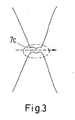
- FIG. 2a therein shows a contact area 7a of two heat exchanger plates 2.
- the contact area is in this case formed by a valley of a top plate meeting a ridge of a bottom plate.
- the contact area of the two neighboring heat exchanger plates is chosen to be very small.
- FIG. 4 now shows a cut view of a heat exchanger plate according to the invention.
- the heat exchanger plates 2 comprise dimples 8, 9 which protrude in directions perpendicular to the plane of the heat exchanger plate 2.
- the dimple 8 comprises a top 10
- the dimple 9 comprises a bottom 11.
- the top 10 as well as the bottom 11 are in this particular embodiment flat surfaces at the ends of the corresponding dimples 8, 9.
- the lower part of figure 4 here shows a top view of the top 10 and the bottom 11, which here both have a circular shape.
- different shapes of the tops 10 and the bottoms 11 are also possible, for example an oval or a rectangular shape.
- the tops 10 and the bottoms 11 do not necessarily have to be flat, one only has to ensure that the tops 10 and the bottoms 11 of neighboring heat exchanger plates 2 fit together.
- the dimples 8, 9 furthermore comprise flanks 12.
- the flanks 12 directly connect a dimple 8 comprising a top 10 with a dimple 9 comprising a bottom 11.
- the solid lines show dimples 8, 9 with substantially straight flanks 12 while the dashed lines show dimples 8, 9 with substantially tangent-shaped flanks 12. Either way it is ensured that the dimples 8, 9 are elastically deformable.
- the flanks 12 may have one of these shapes between adjacent tops 10 and bottoms 11, but around the circumference of the dimples 8, 9 the shape of the flanks 12 may be different as shown later on.
- Figure 5 shows a top view of a heat exchanger plate 2. This figure also shows how the separation of the two fluids in the heat exchanger 1 is achieved by the gaskets 5.
- a first fluid can enter the fluid pathways adjacent to the top of the plate 2 via the inlet I1 and flow through a plurality of fluid pathways to the outlet O1.
- the second fluid cannot enter the space adjacent to the top of the heat exchanger plate 2, because the inlet I2 as well as the outlet 02 are separated from these fluid pathways by the gasket 5.
- Figure 5 furthermore shows on the right side an enlarged view of a pattern of dimples in the heat exchanger plate 2. Similar to figure 4 dimples 8 comprising tops 10 are represented as unfilled circles while dimples 9 comprising bottoms 11 are represented as filled circles. Furthermore, three different directions of cut views 13, 14a and 14b are shown as solid or dashed lines. The corresponding cut views are shown in figures 6a and 6b .
- the cut view 13 is shown through two neighboring heat exchanger plates 2a, 2b.
- dimples 8 comprising tops 10 are alternating with dimples 9 comprising bottoms 11.
- the flanks 12 are again substantially straight.
- the thickness of the heat exchanger plates 2 may be reduced significantly without risking damages of the type explained in figures 2a, 2b and 3 . Consequently, by reducing the thickness of the heat exchanger plates 2 one may improve the heat transfer from one fluid to the other, thus achieving a better efficiency of the heat exchanger 1.
- Figure 6b shows two neighboring heat exchanger plates 2a, 2b along the cut views 14a and 14b.
- the solid lines show the cut view 14a while the dashed lines show the cut view 14b.
- the top heat exchanger plate 2b only shows dimples 9 comprising bottoms 11, while the bottom heat exchanger plate 2a only shows dimples 8 comprising tops 10. Again the bottoms 11 of the top heat exchanger plate 2b are in contact with the tops 10 of the bottom heat exchanger plate 2a.
- the top heat exchanger plate 2b only shows dimples 8 comprising tops 10 while the bottom heat exchanger plate 2a only shows dimples 9 comprising bottoms 11.
- the heat exchanger plates 2a and 2b do not show any contact areas.
- Figure 6b furthermore shows that the flanks 12 of the dimples 8, 9 along the cut views 14a, 14b may be substantially elliptical-shaped between adjacent tops 10 and between adjacent bottoms 11.
- the shape of the flanks 12 may for example change smoothly from a substantially straight form to a substantially elliptical-shaped form when going around the circumference of a dimple 8, 9.
- Figure 7 shows an elastic deformation of a pair of dimples 8, 9 in contact with each other at a top 10 and a bottom 11.
- Figure 7 shows a situation in which the forces 4 pressing the heat exchanger plates 2a, 2b together are of similar or equal size. This will usually be the case, since forces 4 resulting in part from the difference of a first pressure P1 of a first medium to a second pressure P2 of a second medium will be equally large in "upward” and in "downward” direction.
- the flanks 12 will deform elastically from a non-deformed shape 12a shown by solid lines into a elastically deformed shape 12b shown by dashed lines.
- the elastic deformations of the flanks 12 as well as the tops 10 and bottoms 11 will result in spring forces acting against the external forces 4. Once the external forces 4 are reduced, the elastically deformed dimples 8, 9 will revert to their non-deformed shapes. Consequently, permanent deformations of the contact areas of the heat exchanger plates 2 as shown in figures 2a, 2b and 3 will be prevented by making the dimples elastically deformable.
- Figures 8a, 8b and 8c show different possible patterns of dimples 8, 9 in a heat exchanger plate 2 according to the invention.
- first rows 16 are shown along which dimples 8 comprising tops 10 are arranged.
- second rows 17 are shown along which dimples 9 comprising bottoms 11 are arranged.
- at least part of the first rows 16 as well as the second rows 17 are arranged parallel to an edge 18 of the heat exchanger plate 2.
- At least part of the first and second rows 16, 17 are arranged at an angle to the edge 18 of the heat exchanger plate 2.
- the angle is for example chosen to be in the range of 20° to less than 45°.
- direct pathways from the first inlet I1 to the first outlet O1 can thus be prevented.
- part of the first and second rows 16, 17 form wedges 19 in the plane of the heat exchanger plate. Consequently, the first and second rows 16, 17 change direction in the plane of the heat exchanger plate 2.
- the first and second rows may also change direction several times within the plane of the heat exchanger plate 2, for example forming zigzag lines. This way one may ensure that the fluid has to change direction at least several times when flowing from the first inlet I1 to the first outlet O1.
Landscapes
- Engineering & Computer Science (AREA)
- Physics & Mathematics (AREA)
- Thermal Sciences (AREA)
- Mechanical Engineering (AREA)
- General Engineering & Computer Science (AREA)
- Heat-Exchange Devices With Radiators And Conduit Assemblies (AREA)
Claims (8)
- Échangeur de chaleur à joint d'étanchéité comprenant une pluralité de plaques d'échangeur de chaleur (2), dans lequel chacune des plaques d'échangeur de chaleur comprend une pluralité d'alvéoles (8, 9) et dans lequel les alvéoles comprennent des parties supérieures (10) et des parties inférieures (11) en tant que plates-formes de contact pour les plaques d'échangeur de chaleur (2), et des flancs (12) et dans lequel les parties supérieures (10) d'au moins une plaque d'échangeur de chaleur sont raccordées à des parties inférieures (11) d'une autre plaque d'échangeur de chaleur voisine, dans lequel les alvéoles (8, 9) peuvent être déformées de manière élastique et les parties supérieures (10) ainsi que les parties inférieures (11) peuvent être déformées de manière élastique dans une direction perpendiculaire au plan des plaques d'échangeur de chaleur (2) et dans lequel l'échangeur de chaleur à joint d'étanchéité comprend des plaques supérieure et inférieure (3), dans lequel la pluralité de plaques d'échangeur de chaleur (2) sont disposées entre les plaques supérieure et inférieure (3), dans lequel les flancs (12) sont sensiblement droits entre des parties supérieures adjacentes (10) et des parties inférieures adjacentes (11), caractérisé en ce que les plaques d'échangeur de chaleur (2) sont maintenues ensemble sous prétension par les plaques supérieure et inférieure (3), dans lequel les flancs (12) peuvent être déformés de manière élastique sous la prétension résultant de forces de ressort agissant contre les forces externes, lesdites forces étant en particulier provoquées par les pressions de fluide.
- Échangeur de chaleur à joint d'étanchéité selon la revendication 1, caractérisé en ce qu'au moins une partie des alvéoles (8) comprenant des parties supérieures (10) sont disposées dans des premières rangées (16) et qu'au moins une partie des alvéoles (9) comprenant des parties inférieures (11) sont disposées dans des secondes rangées (17).
- Échangeur de chaleur à joint d'étanchéité selon la revendication 2, caractérisé en ce qu'au moins une partie des premières et secondes rangées (16, 17) sont disposées parallèlement à un bord (18) de la plaque d'échangeur de chaleur (2).
- Échangeur de chaleur à joint d'étanchéité selon la revendication 2 ou 3, caractérisé en ce qu'au moins une partie des premières et secondes rangées (16, 17) sont disposées de sorte à former un angle avec un bord (18) de la plaque d'échangeur de chaleur (2).
- Échangeur de chaleur à joint d'étanchéité selon l'une quelconque des revendications 2 à 4, caractérisé en ce qu'au moins une partie des premières et secondes rangées (16, 17) change de direction dans le plan de la plaque d'échangeur de chaleur (2).
- Échangeur de chaleur à joint d'étanchéité selon l'une quelconque des revendications 2 à 5, caractérisé en ce qu'au moins une partie des premières et secondes rangées (16, 17) forment des coins (19) dans le plan de la plaque d'échangeur de chaleur (2).
- Échangeur de chaleur à joint d'étanchéité selon l'une quelconque des revendications précédentes, caractérisé en ce que les parties supérieures (10) et les parties inférieures (11) sont sensiblement plates de telle sorte qu'un plan plat d'une partie supérieure (10) rencontre un plan plat d'une partie inférieure (11) lorsque des plaques d'échangeur de chaleur (2) sont raccordées.
- Échangeur de chaleur à joint d'étanchéité selon la revendication 7, caractérisé en ce que des alvéoles (8, 9) présentent des formes similaires.
Priority Applications (2)
| Application Number | Priority Date | Filing Date | Title |
|---|---|---|---|
| SI201430798T SI2775246T1 (sl) | 2013-03-08 | 2014-02-05 | Zatesnjen izmenjevalnik toplote, ki ima vdolbinast vzorec |
| PL14153900T PL2775246T3 (pl) | 2013-03-08 | 2014-02-05 | Mający układ zagłębień, uszczelkowy wymiennik ciepła |
Applications Claiming Priority (1)
| Application Number | Priority Date | Filing Date | Title |
|---|---|---|---|
| DK201300120A DK177838B1 (en) | 2013-03-08 | 2013-03-08 | A gasketed heat exchanger with elastically deformable dimples |
Publications (3)
| Publication Number | Publication Date |
|---|---|
| EP2775246A2 EP2775246A2 (fr) | 2014-09-10 |
| EP2775246A3 EP2775246A3 (fr) | 2015-09-02 |
| EP2775246B1 true EP2775246B1 (fr) | 2018-06-20 |
Family
ID=50030215
Family Applications (1)
| Application Number | Title | Priority Date | Filing Date |
|---|---|---|---|
| EP14153900.7A Active EP2775246B1 (fr) | 2013-03-08 | 2014-02-05 | Échangeur de chaleur avec joint d'étanchéité, à motif d'alvéoles |
Country Status (7)
| Country | Link |
|---|---|
| US (1) | US10145625B2 (fr) |
| EP (1) | EP2775246B1 (fr) |
| CN (1) | CN104034189B (fr) |
| DK (1) | DK177838B1 (fr) |
| PL (1) | PL2775246T3 (fr) |
| RU (1) | RU2562347C1 (fr) |
| SI (1) | SI2775246T1 (fr) |
Families Citing this family (6)
| Publication number | Priority date | Publication date | Assignee | Title |
|---|---|---|---|---|
| DK177839B1 (en) | 2013-03-08 | 2014-09-08 | Danfoss As | Heat exchanger with dimples connected by wall sections |
| US20160223262A1 (en) * | 2014-10-31 | 2016-08-04 | Baltimore Aircoil Company, Inc. | Cooling tower integrated inlet louver fill |
| EP3182048A1 (fr) * | 2015-12-16 | 2017-06-21 | Alfa Laval Corporate AB | Joint de perforation, ensemble pour un échangeur de chaleur et échangeur de chaleur comportant un tel ensemble |
| CN107036479B (zh) * | 2016-02-04 | 2020-05-12 | 丹佛斯微通道换热器(嘉兴)有限公司 | 换热板以及使用其的板式换热器 |
| GB2552956A (en) * | 2016-08-15 | 2018-02-21 | Hs Marston Aerospace Ltd | Heat exchanger device |
| SE544426C2 (en) * | 2019-04-03 | 2022-05-24 | Alfa Laval Corp Ab | A heat exchanger plate, and a plate heat exchanger |
Family Cites Families (40)
| Publication number | Priority date | Publication date | Assignee | Title |
|---|---|---|---|---|
| US2281754A (en) | 1937-01-27 | 1942-05-05 | Cherry Burreil Corp | Heat exchanger |
| US2441476A (en) * | 1944-08-10 | 1948-05-11 | Glenn L Martin Co | Reinforced structural sheet |
| US2481046A (en) * | 1947-11-13 | 1949-09-06 | Western Engineering Associates | Panel structure |
| US2577321A (en) * | 1949-10-29 | 1951-12-04 | Joseph B Filger | Nose drop dispenser |
| US2627283A (en) | 1950-11-27 | 1953-02-03 | Fedders Quigan Corp | Heat exchange conduit for oil coolers |
| GB901914A (en) * | 1959-12-02 | 1962-07-25 | Nat Res Dev | Improvements in or relating to heat exchangers |
| US3532161A (en) * | 1968-06-27 | 1970-10-06 | Aqua Chem Inc | Plate type heat exchanger |
| US3597891A (en) * | 1969-10-02 | 1971-08-10 | Mc Donnell Douglas Corp | Interior absorptive panel |
| US3664928A (en) | 1969-12-15 | 1972-05-23 | Aerojet General Co | Dimpled heat transfer walls for distillation apparatus |
| SE353954B (fr) | 1971-02-19 | 1973-02-19 | Alfa Laval Ab | |
| US3742663A (en) * | 1971-08-02 | 1973-07-03 | Mc Donnell Douglas Corp | Panel blocking |
| US3956543A (en) * | 1972-10-02 | 1976-05-11 | Rockwell International Corporation | Shear flexibility for structures |
| GB1468514A (en) * | 1974-06-07 | 1977-03-30 | Apv Co Ltd | Plate heat exchangers |
| SE415928B (sv) * | 1979-01-17 | 1980-11-10 | Alfa Laval Ab | Plattvermevexlare |
| US4471759A (en) | 1981-04-28 | 1984-09-18 | B. Shawn Buckley | Method of forming a solar collector or hot water storage tank and solar water heating apparatus using same |
| SU1257402A2 (ru) | 1984-09-07 | 1986-09-15 | Ярославский Моторный Завод "Автодизель" | Пластинчатый теплообменник |
| DE3622316C1 (de) * | 1986-07-03 | 1988-01-28 | Schmidt W Gmbh Co Kg | Plattenwaermeaustauscher |
| SE458806B (sv) | 1987-04-21 | 1989-05-08 | Alfa Laval Thermal Ab | Plattvaermevaexlare med olika stroemningsmotstaand foer medierna |
| US4919200A (en) | 1989-05-01 | 1990-04-24 | Stanislas Glomski | Heat exchanger wall assembly |
| SE468685B (sv) | 1991-06-24 | 1993-03-01 | Alfa Laval Thermal Ab | Plattvaermevaexlare med plattor som har aasar och raennor daer aasar paa en platta anligger mot parallellt med desamma loepande aasar paa den andra plattan |
| JPH0942865A (ja) | 1995-07-28 | 1997-02-14 | Honda Motor Co Ltd | 熱交換器 |
| US5643656A (en) | 1995-08-14 | 1997-07-01 | Lin; Tso Nan | Packing cushion board |
| SE9503241D0 (sv) * | 1995-09-26 | 1995-09-26 | Tetra Laval Holdings & Finance | Plattvärmeväxlare |
| US5968321A (en) * | 1996-02-13 | 1999-10-19 | Ridgewood Waterpure Corporation | Vapor compression distillation system and method |
| JP4072876B2 (ja) | 1998-05-22 | 2008-04-09 | セキサーマル株式会社 | 積層型熱交換器 |
| US6221463B1 (en) * | 1998-07-08 | 2001-04-24 | Eugene W. White | Three-dimensional film structures and methods |
| US6681844B1 (en) * | 1998-10-15 | 2004-01-27 | Ebara Corporation | Plate type heat exchanger |
| RU2164332C2 (ru) | 1999-03-02 | 2001-03-20 | Открытое акционерное общество Уральский торговый дом "Логика" | Пакет пластин для теплообменника |
| US6357516B1 (en) * | 2000-02-02 | 2002-03-19 | York International Corporation | Plate heat exchanger assembly with enhanced heat transfer characteristics |
| SE518256C2 (sv) * | 2001-01-04 | 2002-09-17 | Alfa Laval Ab | Värmeöverföringsplatta, plattpaket samt plattvärmeväxlare |
| US6595273B2 (en) | 2001-08-08 | 2003-07-22 | Denso Corporation | Heat exchanger |
| SE528629C2 (sv) * | 2004-09-08 | 2007-01-09 | Ep Technology Ab | Rillmönster för värmeväxlare |
| US20110180247A1 (en) * | 2004-09-08 | 2011-07-28 | Ep Technology Ab | Heat exchanger |
| US20070006998A1 (en) * | 2005-07-07 | 2007-01-11 | Viktor Brost | Heat exchanger with plate projections |
| EP1933105A1 (fr) * | 2006-12-11 | 2008-06-18 | Invensys APV A/S | Plaque d'échangeur thermique |
| WO2009112031A2 (fr) | 2008-03-13 | 2009-09-17 | Danfoss A/S | Échangeur de chaleur à double plaque |
| EP2257756B1 (fr) * | 2008-04-04 | 2014-10-08 | Alfa Laval Corporate AB | Échangeur de chaleur à plaques |
| US20110120934A1 (en) | 2009-11-24 | 2011-05-26 | Air To Air Sweden Ab | Method of producing multiple channels for use in a device for exchange of solutes between fluid flows |
| JP5631287B2 (ja) * | 2011-09-30 | 2014-11-26 | 株式会社神戸製鋼所 | 熱交換用プレートの元板材、及び熱交換用プレートの元板材の製造方法 |
| DK177839B1 (en) | 2013-03-08 | 2014-09-08 | Danfoss As | Heat exchanger with dimples connected by wall sections |
-
2013
- 2013-03-08 DK DK201300120A patent/DK177838B1/en not_active IP Right Cessation
-
2014
- 2014-02-05 EP EP14153900.7A patent/EP2775246B1/fr active Active
- 2014-02-05 PL PL14153900T patent/PL2775246T3/pl unknown
- 2014-02-05 SI SI201430798T patent/SI2775246T1/sl unknown
- 2014-03-04 US US14/196,209 patent/US10145625B2/en active Active
- 2014-03-05 RU RU2014108234/06A patent/RU2562347C1/ru active
- 2014-03-10 CN CN201410085403.0A patent/CN104034189B/zh not_active Expired - Fee Related
Non-Patent Citations (1)
| Title |
|---|
| None * |
Also Published As
| Publication number | Publication date |
|---|---|
| US20140251586A1 (en) | 2014-09-11 |
| SI2775246T1 (sl) | 2018-09-28 |
| RU2562347C1 (ru) | 2015-09-10 |
| DK177838B1 (en) | 2014-09-08 |
| EP2775246A2 (fr) | 2014-09-10 |
| US10145625B2 (en) | 2018-12-04 |
| EP2775246A3 (fr) | 2015-09-02 |
| PL2775246T3 (pl) | 2018-11-30 |
| CN104034189A (zh) | 2014-09-10 |
| CN104034189B (zh) | 2017-12-19 |
Similar Documents
| Publication | Publication Date | Title |
|---|---|---|
| EP2775246B1 (fr) | Échangeur de chaleur avec joint d'étanchéité, à motif d'alvéoles | |
| EP2775247B1 (fr) | Échangeur de chaleur à double motif d'alvéoles | |
| RU2598982C1 (ru) | Теплопередающая пластина и пластинчатый теплообменник, содержащий такую теплопередающую пластину | |
| CN110537069B (zh) | 热传递板和包括多个此类热传递板的热交换器 | |
| US6237679B1 (en) | Plate heat exchangers | |
| KR20060089162A (ko) | 열 교환용 플레이트 | |
| EP1723376A1 (fr) | Plaque d'echangeur thermique et bloc de plaques | |
| KR20130031848A (ko) | 열교환판과 판형 열교환기 | |
| EP3017261B1 (fr) | Echangeur asymétrique comportant des canaux auxiliaires pour relier des courbures | |
| JP2008116138A (ja) | 熱交換用プレート | |
| JP2007010202A (ja) | 熱交換ユニット | |
| WO2017167598A1 (fr) | Plaque de transfert de chaleur et échangeur de chaleur à plaques comprenant une pluralité de telles plaques de transfert de chaleur | |
| JP4666463B2 (ja) | 熱交換用プレート | |
| EP3032208B1 (fr) | Rainure de joint d'étanchéité pour un échangeur de chaleur à plaques | |
| JP2006317029A (ja) | 熱交換ユニット | |
| JP2004184075A (ja) | 伝熱プレート及びプレート式熱交換器 | |
| JP7214923B2 (ja) | 熱伝達プレート | |
| KR20180115755A (ko) | 판 열교환기를 위한 열교환기 판, 및 판 열교환기 | |
| JP3543993B2 (ja) | プレート式熱交換器 | |
| KR20050073424A (ko) | 열교환용 플레이트 및 열교환 유닛 |
Legal Events
| Date | Code | Title | Description |
|---|---|---|---|
| PUAI | Public reference made under article 153(3) epc to a published international application that has entered the european phase |
Free format text: ORIGINAL CODE: 0009012 |
|
| 17P | Request for examination filed |
Effective date: 20140205 |
|
| AK | Designated contracting states |
Kind code of ref document: A2 Designated state(s): AL AT BE BG CH CY CZ DE DK EE ES FI FR GB GR HR HU IE IS IT LI LT LU LV MC MK MT NL NO PL PT RO RS SE SI SK SM TR |
|
| AX | Request for extension of the european patent |
Extension state: BA ME |
|
| PUAL | Search report despatched |
Free format text: ORIGINAL CODE: 0009013 |
|
| AK | Designated contracting states |
Kind code of ref document: A3 Designated state(s): AL AT BE BG CH CY CZ DE DK EE ES FI FR GB GR HR HU IE IS IT LI LT LU LV MC MK MT NL NO PL PT RO RS SE SI SK SM TR |
|
| AX | Request for extension of the european patent |
Extension state: BA ME |
|
| RIC1 | Information provided on ipc code assigned before grant |
Ipc: F28F 3/04 20060101AFI20150727BHEP Ipc: F28F 3/08 20060101ALI20150727BHEP |
|
| R17P | Request for examination filed (corrected) |
Effective date: 20160216 |
|
| RBV | Designated contracting states (corrected) |
Designated state(s): AL AT BE BG CH CY CZ DE DK EE ES FI FR GB GR HR HU IE IS IT LI LT LU LV MC MK MT NL NO PL PT RO RS SE SI SK SM TR |
|
| STAA | Information on the status of an ep patent application or granted ep patent |
Free format text: STATUS: EXAMINATION IS IN PROGRESS |
|
| 17Q | First examination report despatched |
Effective date: 20170316 |
|
| GRAP | Despatch of communication of intention to grant a patent |
Free format text: ORIGINAL CODE: EPIDOSNIGR1 |
|
| STAA | Information on the status of an ep patent application or granted ep patent |
Free format text: STATUS: GRANT OF PATENT IS INTENDED |
|
| INTG | Intention to grant announced |
Effective date: 20180403 |
|
| GRAS | Grant fee paid |
Free format text: ORIGINAL CODE: EPIDOSNIGR3 |
|
| GRAA | (expected) grant |
Free format text: ORIGINAL CODE: 0009210 |
|
| STAA | Information on the status of an ep patent application or granted ep patent |
Free format text: STATUS: THE PATENT HAS BEEN GRANTED |
|
| AK | Designated contracting states |
Kind code of ref document: B1 Designated state(s): AL AT BE BG CH CY CZ DE DK EE ES FI FR GB GR HR HU IE IS IT LI LT LU LV MC MK MT NL NO PL PT RO RS SE SI SK SM TR |
|
| REG | Reference to a national code |
Ref country code: GB Ref legal event code: FG4D |
|
| REG | Reference to a national code |
Ref country code: IE Ref legal event code: FG4D |
|
| REG | Reference to a national code |
Ref country code: RO Ref legal event code: EPE |
|
| REG | Reference to a national code |
Ref country code: AT Ref legal event code: REF Ref document number: 1010901 Country of ref document: AT Kind code of ref document: T Effective date: 20180715 |
|
| REG | Reference to a national code |
Ref country code: DE Ref legal event code: R096 Ref document number: 602014027204 Country of ref document: DE |
|
| REG | Reference to a national code |
Ref country code: NL Ref legal event code: FP |
|
| REG | Reference to a national code |
Ref country code: SE Ref legal event code: TRGR |
|
| PG25 | Lapsed in a contracting state [announced via postgrant information from national office to epo] |
Ref country code: BG Free format text: LAPSE BECAUSE OF FAILURE TO SUBMIT A TRANSLATION OF THE DESCRIPTION OR TO PAY THE FEE WITHIN THE PRESCRIBED TIME-LIMIT Effective date: 20180920 Ref country code: NO Free format text: LAPSE BECAUSE OF FAILURE TO SUBMIT A TRANSLATION OF THE DESCRIPTION OR TO PAY THE FEE WITHIN THE PRESCRIBED TIME-LIMIT Effective date: 20180920 Ref country code: LT Free format text: LAPSE BECAUSE OF FAILURE TO SUBMIT A TRANSLATION OF THE DESCRIPTION OR TO PAY THE FEE WITHIN THE PRESCRIBED TIME-LIMIT Effective date: 20180620 |
|
| REG | Reference to a national code |
Ref country code: LT Ref legal event code: MG4D |
|
| PG25 | Lapsed in a contracting state [announced via postgrant information from national office to epo] |
Ref country code: GR Free format text: LAPSE BECAUSE OF FAILURE TO SUBMIT A TRANSLATION OF THE DESCRIPTION OR TO PAY THE FEE WITHIN THE PRESCRIBED TIME-LIMIT Effective date: 20180921 Ref country code: HR Free format text: LAPSE BECAUSE OF FAILURE TO SUBMIT A TRANSLATION OF THE DESCRIPTION OR TO PAY THE FEE WITHIN THE PRESCRIBED TIME-LIMIT Effective date: 20180620 Ref country code: LV Free format text: LAPSE BECAUSE OF FAILURE TO SUBMIT A TRANSLATION OF THE DESCRIPTION OR TO PAY THE FEE WITHIN THE PRESCRIBED TIME-LIMIT Effective date: 20180620 Ref country code: RS Free format text: LAPSE BECAUSE OF FAILURE TO SUBMIT A TRANSLATION OF THE DESCRIPTION OR TO PAY THE FEE WITHIN THE PRESCRIBED TIME-LIMIT Effective date: 20180620 |
|
| PG25 | Lapsed in a contracting state [announced via postgrant information from national office to epo] |
Ref country code: CZ Free format text: LAPSE BECAUSE OF FAILURE TO SUBMIT A TRANSLATION OF THE DESCRIPTION OR TO PAY THE FEE WITHIN THE PRESCRIBED TIME-LIMIT Effective date: 20180620 Ref country code: IS Free format text: LAPSE BECAUSE OF FAILURE TO SUBMIT A TRANSLATION OF THE DESCRIPTION OR TO PAY THE FEE WITHIN THE PRESCRIBED TIME-LIMIT Effective date: 20181020 Ref country code: EE Free format text: LAPSE BECAUSE OF FAILURE TO SUBMIT A TRANSLATION OF THE DESCRIPTION OR TO PAY THE FEE WITHIN THE PRESCRIBED TIME-LIMIT Effective date: 20180620 Ref country code: SK Free format text: LAPSE BECAUSE OF FAILURE TO SUBMIT A TRANSLATION OF THE DESCRIPTION OR TO PAY THE FEE WITHIN THE PRESCRIBED TIME-LIMIT Effective date: 20180620 |
|
| PG25 | Lapsed in a contracting state [announced via postgrant information from national office to epo] |
Ref country code: ES Free format text: LAPSE BECAUSE OF FAILURE TO SUBMIT A TRANSLATION OF THE DESCRIPTION OR TO PAY THE FEE WITHIN THE PRESCRIBED TIME-LIMIT Effective date: 20180620 Ref country code: SM Free format text: LAPSE BECAUSE OF FAILURE TO SUBMIT A TRANSLATION OF THE DESCRIPTION OR TO PAY THE FEE WITHIN THE PRESCRIBED TIME-LIMIT Effective date: 20180620 |
|
| REG | Reference to a national code |
Ref country code: DE Ref legal event code: R097 Ref document number: 602014027204 Country of ref document: DE |
|
| PLBE | No opposition filed within time limit |
Free format text: ORIGINAL CODE: 0009261 |
|
| STAA | Information on the status of an ep patent application or granted ep patent |
Free format text: STATUS: NO OPPOSITION FILED WITHIN TIME LIMIT |
|
| 26N | No opposition filed |
Effective date: 20190321 |
|
| PG25 | Lapsed in a contracting state [announced via postgrant information from national office to epo] |
Ref country code: DK Free format text: LAPSE BECAUSE OF FAILURE TO SUBMIT A TRANSLATION OF THE DESCRIPTION OR TO PAY THE FEE WITHIN THE PRESCRIBED TIME-LIMIT Effective date: 20180620 |
|
| REG | Reference to a national code |
Ref country code: CH Ref legal event code: PL |
|
| PG25 | Lapsed in a contracting state [announced via postgrant information from national office to epo] |
Ref country code: MC Free format text: LAPSE BECAUSE OF FAILURE TO SUBMIT A TRANSLATION OF THE DESCRIPTION OR TO PAY THE FEE WITHIN THE PRESCRIBED TIME-LIMIT Effective date: 20180620 Ref country code: LU Free format text: LAPSE BECAUSE OF NON-PAYMENT OF DUE FEES Effective date: 20190205 |
|
| REG | Reference to a national code |
Ref country code: AT Ref legal event code: UEP Ref document number: 1010901 Country of ref document: AT Kind code of ref document: T Effective date: 20180620 |
|
| REG | Reference to a national code |
Ref country code: BE Ref legal event code: MM Effective date: 20190228 |
|
| REG | Reference to a national code |
Ref country code: IE Ref legal event code: MM4A |
|
| PG25 | Lapsed in a contracting state [announced via postgrant information from national office to epo] |
Ref country code: AL Free format text: LAPSE BECAUSE OF FAILURE TO SUBMIT A TRANSLATION OF THE DESCRIPTION OR TO PAY THE FEE WITHIN THE PRESCRIBED TIME-LIMIT Effective date: 20180620 |
|
| PG25 | Lapsed in a contracting state [announced via postgrant information from national office to epo] |
Ref country code: LI Free format text: LAPSE BECAUSE OF NON-PAYMENT OF DUE FEES Effective date: 20190228 Ref country code: CH Free format text: LAPSE BECAUSE OF NON-PAYMENT OF DUE FEES Effective date: 20190228 |
|
| PG25 | Lapsed in a contracting state [announced via postgrant information from national office to epo] |
Ref country code: IE Free format text: LAPSE BECAUSE OF NON-PAYMENT OF DUE FEES Effective date: 20190205 |
|
| PG25 | Lapsed in a contracting state [announced via postgrant information from national office to epo] |
Ref country code: BE Free format text: LAPSE BECAUSE OF NON-PAYMENT OF DUE FEES Effective date: 20190228 |
|
| PG25 | Lapsed in a contracting state [announced via postgrant information from national office to epo] |
Ref country code: PT Free format text: LAPSE BECAUSE OF FAILURE TO SUBMIT A TRANSLATION OF THE DESCRIPTION OR TO PAY THE FEE WITHIN THE PRESCRIBED TIME-LIMIT Effective date: 20181022 Ref country code: MT Free format text: LAPSE BECAUSE OF NON-PAYMENT OF DUE FEES Effective date: 20190205 |
|
| PG25 | Lapsed in a contracting state [announced via postgrant information from national office to epo] |
Ref country code: CY Free format text: LAPSE BECAUSE OF FAILURE TO SUBMIT A TRANSLATION OF THE DESCRIPTION OR TO PAY THE FEE WITHIN THE PRESCRIBED TIME-LIMIT Effective date: 20180620 |
|
| PG25 | Lapsed in a contracting state [announced via postgrant information from national office to epo] |
Ref country code: HU Free format text: LAPSE BECAUSE OF FAILURE TO SUBMIT A TRANSLATION OF THE DESCRIPTION OR TO PAY THE FEE WITHIN THE PRESCRIBED TIME-LIMIT; INVALID AB INITIO Effective date: 20140205 |
|
| PGFP | Annual fee paid to national office [announced via postgrant information from national office to epo] |
Ref country code: GB Payment date: 20220106 Year of fee payment: 9 Ref country code: FI Payment date: 20220209 Year of fee payment: 9 Ref country code: DE Payment date: 20220105 Year of fee payment: 9 Ref country code: AT Payment date: 20220125 Year of fee payment: 9 |
|
| PGFP | Annual fee paid to national office [announced via postgrant information from national office to epo] |
Ref country code: TR Payment date: 20220203 Year of fee payment: 9 Ref country code: SE Payment date: 20220110 Year of fee payment: 9 Ref country code: RO Payment date: 20220127 Year of fee payment: 9 Ref country code: PL Payment date: 20220112 Year of fee payment: 9 Ref country code: NL Payment date: 20220118 Year of fee payment: 9 Ref country code: IT Payment date: 20220111 Year of fee payment: 9 Ref country code: FR Payment date: 20220127 Year of fee payment: 9 |
|
| PG25 | Lapsed in a contracting state [announced via postgrant information from national office to epo] |
Ref country code: MK Free format text: LAPSE BECAUSE OF FAILURE TO SUBMIT A TRANSLATION OF THE DESCRIPTION OR TO PAY THE FEE WITHIN THE PRESCRIBED TIME-LIMIT Effective date: 20180620 |
|
| PGFP | Annual fee paid to national office [announced via postgrant information from national office to epo] |
Ref country code: SI Payment date: 20220118 Year of fee payment: 9 |
|
| REG | Reference to a national code |
Ref country code: DE Ref legal event code: R119 Ref document number: 602014027204 Country of ref document: DE |
|
| REG | Reference to a national code |
Ref country code: SE Ref legal event code: EUG |
|
| REG | Reference to a national code |
Ref country code: NL Ref legal event code: MM Effective date: 20230301 |
|
| REG | Reference to a national code |
Ref country code: AT Ref legal event code: MM01 Ref document number: 1010901 Country of ref document: AT Kind code of ref document: T Effective date: 20230205 |
|
| GBPC | Gb: european patent ceased through non-payment of renewal fee |
Effective date: 20230205 |
|
| PG25 | Lapsed in a contracting state [announced via postgrant information from national office to epo] |
Ref country code: SE Free format text: LAPSE BECAUSE OF NON-PAYMENT OF DUE FEES Effective date: 20230206 Ref country code: RO Free format text: LAPSE BECAUSE OF NON-PAYMENT OF DUE FEES Effective date: 20230205 Ref country code: FI Free format text: LAPSE BECAUSE OF NON-PAYMENT OF DUE FEES Effective date: 20230205 Ref country code: AT Free format text: LAPSE BECAUSE OF NON-PAYMENT OF DUE FEES Effective date: 20230205 |
|
| PG25 | Lapsed in a contracting state [announced via postgrant information from national office to epo] |
Ref country code: SI Free format text: LAPSE BECAUSE OF NON-PAYMENT OF DUE FEES Effective date: 20230206 Ref country code: NL Free format text: LAPSE BECAUSE OF NON-PAYMENT OF DUE FEES Effective date: 20230301 |
|
| REG | Reference to a national code |
Ref country code: SI Ref legal event code: KO00 Effective date: 20231023 |
|
| PG25 | Lapsed in a contracting state [announced via postgrant information from national office to epo] |
Ref country code: GB Free format text: LAPSE BECAUSE OF NON-PAYMENT OF DUE FEES Effective date: 20230205 |
|
| PG25 | Lapsed in a contracting state [announced via postgrant information from national office to epo] |
Ref country code: IT Free format text: LAPSE BECAUSE OF NON-PAYMENT OF DUE FEES Effective date: 20230205 Ref country code: GB Free format text: LAPSE BECAUSE OF NON-PAYMENT OF DUE FEES Effective date: 20230205 Ref country code: FR Free format text: LAPSE BECAUSE OF NON-PAYMENT OF DUE FEES Effective date: 20230228 Ref country code: DE Free format text: LAPSE BECAUSE OF NON-PAYMENT OF DUE FEES Effective date: 20230901 |
|
| PG25 | Lapsed in a contracting state [announced via postgrant information from national office to epo] |
Ref country code: PL Free format text: LAPSE BECAUSE OF NON-PAYMENT OF DUE FEES Effective date: 20230205 |
|
| PG25 | Lapsed in a contracting state [announced via postgrant information from national office to epo] |
Ref country code: PL Free format text: LAPSE BECAUSE OF NON-PAYMENT OF DUE FEES Effective date: 20230205 |