EP3017109B1 - Siebvorrichtung - Google Patents
Siebvorrichtung Download PDFInfo
- Publication number
- EP3017109B1 EP3017109B1 EP14733082.3A EP14733082A EP3017109B1 EP 3017109 B1 EP3017109 B1 EP 3017109B1 EP 14733082 A EP14733082 A EP 14733082A EP 3017109 B1 EP3017109 B1 EP 3017109B1
- Authority
- EP
- European Patent Office
- Prior art keywords
- sieve
- intermediate ring
- baskets
- accordance
- basket
- Prior art date
- Legal status (The legal status is an assumption and is not a legal conclusion. Google has not performed a legal analysis and makes no representation as to the accuracy of the status listed.)
- Not-in-force
Links
- 238000012216 screening Methods 0.000 title description 45
- 230000003014 reinforcing effect Effects 0.000 claims description 30
- 230000002787 reinforcement Effects 0.000 claims description 5
- 239000000725 suspension Substances 0.000 claims description 3
- 229920001971 elastomer Polymers 0.000 claims description 2
- 239000000806 elastomer Substances 0.000 claims description 2
- 230000006978 adaptation Effects 0.000 description 3
- 238000004519 manufacturing process Methods 0.000 description 3
- 238000007873 sieving Methods 0.000 description 3
- 230000003321 amplification Effects 0.000 description 2
- 238000010276 construction Methods 0.000 description 2
- 238000003199 nucleic acid amplification method Methods 0.000 description 2
- 239000000853 adhesive Substances 0.000 description 1
- 230000001070 adhesive effect Effects 0.000 description 1
- 150000001875 compounds Chemical class 0.000 description 1
- 230000007423 decrease Effects 0.000 description 1
- 230000001419 dependent effect Effects 0.000 description 1
- 238000009434 installation Methods 0.000 description 1
- 230000003993 interaction Effects 0.000 description 1
- 238000000034 method Methods 0.000 description 1
- 239000011295 pitch Substances 0.000 description 1
- 238000000926 separation method Methods 0.000 description 1
- 229910000679 solder Inorganic materials 0.000 description 1
- 238000003466 welding Methods 0.000 description 1
Images


Classifications
-
- D—TEXTILES; PAPER
- D21—PAPER-MAKING; PRODUCTION OF CELLULOSE
- D21D—TREATMENT OF THE MATERIALS BEFORE PASSING TO THE PAPER-MAKING MACHINE
- D21D5/00—Purification of the pulp suspension by mechanical means; Apparatus therefor
- D21D5/02—Straining or screening the pulp
- D21D5/16—Cylinders and plates for screens
-
- B—PERFORMING OPERATIONS; TRANSPORTING
- B07—SEPARATING SOLIDS FROM SOLIDS; SORTING
- B07B—SEPARATING SOLIDS FROM SOLIDS BY SIEVING, SCREENING, SIFTING OR BY USING GAS CURRENTS; SEPARATING BY OTHER DRY METHODS APPLICABLE TO BULK MATERIAL, e.g. LOOSE ARTICLES FIT TO BE HANDLED LIKE BULK MATERIAL
- B07B1/00—Sieving, screening, sifting, or sorting solid materials using networks, gratings, grids, or the like
- B07B1/18—Drum screens
Definitions
- the invention relates to a screening device which is intended for pulp suspensions in the paper industry and is used, for example, in sorters, pressure sorters and the like.
- a screening device of the generic type which has a screen surface forming, substantially cylindrical screening device.
- the screening device is supported by a radially spaced arranged reinforcing device, which is designed in particular in the form of a support shell, which is also referred to as a "backup cylinder".
- the screening device is interchangeable as a unit to replace the heavily used and prone to wear screen device in a simple way and to be able to use the reinforcing device, such as the support shell again.
- the screening device and the amplifying device are non-positively into each other set, and if necessary, this compound can still be secured, for example by means of welding, rivets, screws, adhesives, solder or the like.
- the screening device is a self-consistent structure, which as such and whole within the reinforcing means, in the form of the support jacket with appropriate suitable means is releasably fixed.
- the invention aims to provide a screening device of the generic type which is flexibly adaptable to different screening tasks and sieving requirements and can be used to increase efficiency.
- the screening device should be displayed and manufactured inexpensively.
- an assembly-friendly construction is to be created, whereby possible potential assembly errors are avoided, in particular, the smallest possible number of parts to be placed together should be present.
- a screening device for pulp suspensions in the paper industry, with a screen surface forming a substantially cylindrical screen basket and a radially spaced therefrom and surrounding the screen basket reinforcing means, provided in the form of a support shell which has an end flange at one axial end, which is characterized in that the screening device comprises at least two separate screen baskets, which are axially successively arranged within the reinforcing device in the form of a support jacket with the interposition of a variable diameter intermediate ring such that the substantially cylindrical screen baskets in cooperation with the end-side end flange of the reinforcing device, a Cover part, a bottom part and the intermediate ring are centrally positioned clamped and fixed.
- the screening device according to the invention thus comprises a smaller number of parts to be assembled, namely a support shell, at least two screen baskets, an intermediate ring, a bottom part and a cover part.
- the interpretation at the Screening device according to the invention is made such that thanks to the variable diameter intermediate ring, the two axially arranged one behind the other screen baskets are automatically centered and aligned relative to each other in the interior of the reinforcing means in the form of the support shell fixed in a predetermined manner.
- the installation effort and the assembly times for assembling a screening device according to the invention can thereby be particularly optimized, and at the same time a reuse of the reinforcing means in the form of the support shell, ensured.
- variable diameter intermediate ring performs the function of a centric positioning of both baskets with respect to the reinforcing device and at the same time a clamping and locking function in the interaction of associated parts of the reinforcing device and the or the front ends of the baskets. Due to the small number of fitting into one another components can also be largely avoided mounting errors.
- the two screen baskets arranged one behind the other allow each optionally separate and flexible adaptation to the desired screening tasks and sieving requirements. Thus, in a simple manner and structurally simple, a universal adaptation of the screening device to the respective conditions of use is possible.
- the diameter variable intermediate ring is divided, preferably slotted.
- the variable diameter intermediate ring may be formed by an elastomeric ring.
- the intermediate ring is designed such that the diameter under the action of an axial, the parts of the screening device against each other spanning clamping force can expand or spread in diameter such that the baskets are aligned relative to each other and also relative to the support center, and at the same time also made a determination in this position.
- the cover part and the bottom part in cooperation with the front ends (Siebkorbflansch) of the screen baskets each form a torsion-proof unit.
- an anti-rotation at the respective ends of the screen baskets or the Siebkorbflansche required to effectively prevent relative movement of the two baskets in the operating state.
- the intermediate ring and the front ends of the screen baskets form a torsion-proof unit, so that a safe and reliable and fixed assignment of intermediate ring and screen baskets is given in the screening device according to the invention.
- a twist-proof fixation can also be achieved by means of frictional engagement.
- the rotation is formed by an interlocking pin and groove arrangement.
- This is an embodiment of an anti-rotation device that is simple in terms of design and construction.
- the design is such that the cover part, the bottom part and the intermediate ring form a non-positive connection with the screen baskets by means of a splined connection.
- the wedge connection can be expediently designed as a conical seat connection.
- the screen baskets can have different slot widths and / or slot shapes, in particular they can have different pitches, profile depths, profile sizes or profile inclinations.
- the sieve device according to the invention is designed such that, for its assembly, a first sieve basket is arranged in the reinforcing device under rest on the bottom part, the variable diameter intermediate ring is placed on the upper axial end of the first sieve basket, the second screen basket is arranged thereon, and then the cover part is arranged on the upper axial end of the second screen basket, wherein at an axial Spannkraftbeaufschlagung the above arrangement, the intermediate ring is widened or expanded in diameter and in the radial direction without gaps at the associated axial ends of the Sieve baskets applies. This ensures that during assembly inevitably all possible passage gaps are effectively closed to the entire arrangement of the components.
- the invention specifies a screening device, which in the interior of a backup cylinder serving as an amplification device has one behind the other axially arranged at least two separate screen baskets.
- a screening device which in the interior of a backup cylinder serving as an amplification device has one behind the other axially arranged at least two separate screen baskets.
- the sieve device according to the invention can therefore be composed of easy-to-assemble components that are designed to be easy to assemble.
- the screening device according to the invention comprises the smallest possible number of individual parts to be constructed together.
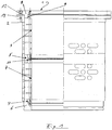
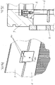
- the screening device 1 comprises a reinforcement device 2 in the form of a support jacket or "backup cylinder".
- a reinforcement device 2 in the form of a support jacket or "backup cylinder".
- two separate baskets 3, 4 are arranged axially one behind the other in the illustrated embodiment.
- a variable diameter intermediate ring 5 is arranged between the two screen baskets 3, 4 , which cooperates with the respective end faces of the two abutting baskets 3, 4 in the manner described in more detail below.
- a bottom part 6 is provided, in which a frontal axial end of the screen basket 4 by means of a spline connection, preferably a conical seat connection 7, is used.
- a spline connection preferably a conical seat connection 7
- the reinforcing device 2 is closed by a cover part 8, which cooperates on the one hand with a top end of a screen basket 3 via a non-positive connection in the form of a wedge connection designed as a conical seat connection 9.
- the lid part 8 is attached to the reinforcing device 2 by means of clamping screws 12.
- An intermediate ring 5 is arranged between the reinforcing device 2 and the two axially mutually facing ends of the two screen baskets 3, 4.
- a first sieve basket 4 is inserted into the interior formed by the reinforcing device 2 in the form of a support cylinder such that the lower axial end face of the screen basket 4 via the frictional connection in the form of a conical seat connection 7, for example, fits on the Floor part 6 rests.
- the diameter variable intermediate ring 5 is placed on the upper axial end of the first screen basket 4.
- the second screen basket 3 is then arranged above the intermediate ring 5 axially aligned with the first screen basket 4 and works via a frictional connection, preferably a spline 11, with the intermediate ring 5 together.
- the lid part 8 is then mounted on the upper axial end of the second screen basket 3 via the non-positive conical seat connection 9.
- clamping screws 12 is an axial Spannkraftbeetzschung the overall arrangement of cover part 8, the two screen baskets 3, 4, the interposed intermediate ring 5 and the bottom part. 6
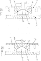
- FIGS. 2a and 2b This Spannkraftbeetzschlagung between the cover part 8, the reinforcing device 2 in the form of a support jacket and the second screen basket 3 is illustrated schematically.
- FIG. 2a the conditions are indicated schematically when the cover part 8 loose over the cone seat connection 9 rests.
- a distance a 1 is present.
- this distance is much smaller after tightening the clamping screws 12 and is designated there with a 2 .
- FIGS. 3a and 3b the operation of the intermediate ring 5 is illustrated schematically.
- FIG. 3a is under assignment to FIG. 2a a schematic representation taken in which the intermediate ring 5 to the inner wall of the reinforcing device 2, for example, a distance b 1 has.
- the two axial ends of the screen baskets 3, 4 have after FIG. 3a for example, a distance a 2 .
- FIG. 3b the condition is shown, if appropriate FIG. 2a an axial clamping force is applied. In this axial clamping force, the axial distance between the two screen baskets 3, 4 is smaller and decreases to a 3 .
- the intermediate ring 10 is pressed directly against the inner wall of the reinforcing device 2 in the form of a support jacket, and the above in FIG. 3a With b 1 designated distance is canceled. In this case, compressive forces can then be transmitted to the reinforcing device 2 via the axial ends (end flanges) of the screen baskets 3, 4 in order to give the screening device 1 an overall increased and better stability.
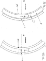
- the intermediate ring 5 is designed to be of variable diameter in that it is split or slotted, which means that this diameter-variable intermediate ring 5 is not closed at its circumferential ends, but a distance c 1 in the circumferential direction is present.
- FIG. 4b under assignment to FIG. 3b can be seen, is spread by the axial Spannkraftbeetzschlagung the intermediate ring 5 in the circumferential direction such that the distance between the circumferential ends of the split intermediate ring 5 is opposite to c 2 FIG. 4a increased. At the same time, the distance b 1 between the inner wall of the reinforcing device 2 is released under the action of the clamping force.
- variable diameter intermediate ring 5 between the two axially opposite ends of the two screen baskets 3, 4 arranged in the interior of the reinforcing device 2 in the form of a support jacket in such a manner that the screen baskets 3, 4 in cooperation with an end-side end flange 13 of the reinforcing device 2 in the form of a support jacket, the cover part 8, the bottom part 6 and the diameter variable intermediate ring 10 are positioned centrally fixed and fixed.
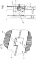
- FIGS. 5a and 5b illustrate an optionally provided anti-rotation 14, which is designed in the example shown as a pin and groove assembly 15. This rotation 14 prevents relative rotation of the cover part 8 and the second screen basket. 3
- an anti-rotation 16 is shown, which is also preferably designed in the form of a pin and groove assembly 17, which is effective between the two axially abutting ends of the two screen baskets 3, 4, and a rotation of the screen baskets 3, 4 relative to each other effectively prevented ,
- FIGS. 7a and 7b is an optionally provided in the lower region anti-rotation 18 illustrates which is also preferably designed as a pin and groove assembly 19 and effectively prevents relative rotation of the first screen basket 4 and the bottom part 6.
- FIGS. 8a and 8b Finally, an alternative embodiment of a variable diameter intermediate ring 5 'is clarified, which is designed in the form of an elastomeric ring 20.
- This elastomer ring 20 has an uninterrupted or continuous configuration and is based on the loosely attached state FIG. 8a under the action of the axial clamping force application accordingly FIG. 8b deformed and pressed, so that even in the FIG. 8b shown state no gap between the inner wall of the reinforcing device 2 and the corresponding axial ends or the end flanges of the two screen baskets 3, 4 is present.
Landscapes
- Engineering & Computer Science (AREA)
- Mechanical Engineering (AREA)
- Paper (AREA)
- Combined Means For Separation Of Solids (AREA)
Description
- Die Erfindung befasst sich mit einer Siebvorrichtung, welche für Faserstoffsuspensionen in der Papierindustrie bestimmt und beispielsweise bei Sortierern, Drucksortierern und dergleichen, eingesetzt wird.
- Aus
EP 1 114 218 B1 ist eine Siebvorrichtung der gattungsgemäßen Art bekannt, welche eine eine Siebfläche bildende, im wesentlichen zylindrische Siebeinrichtung hat. Die Siebeinrichtung ist dabei von einer radial beabstandet angeordneten Verstärkungseinrichtung gestützt, welche insbesondere in Form eines Stützmantels ausgelegt ist, welcher auch als "Backup-Zylinder" bezeichnet wird. Die Siebeinrichtung ist als Einheit auswechselbar, um die stark beanspruchte und zum Verschleiß neigende Siebeinrichtung auf einfache Weise austauschen zu können und die Verstärkungseinrichtung, wie den Stützmantel, wieder verwenden zu können. - Aus
EP 0 471 195 A1 und der zugeordnetenUS-A-5,200,072 sind Siebplatten, Siebzylinder und Verfahren zu deren Herstellung bekannt. Bei einer zylindrischen Siebvorrichtung ist die Auslegung derart getroffen, dass die Siebeinrichtung oder das entsprechende Siebteil lösbar und auswechselbar mit einem als Verstärkungseinrichtung dienenden Stützzylinder verbunden ist. Um die Herstellungskosten und die Herstellungszeit zu reduzieren, braucht daher eine verschlissene Siebeinrichtung nur ausgewechselt zu werden, während die Verstärkungseinrichtung, insbesondere der Stützzylinder, wieder verwendet werden kann. Zur lösbaren Verbindung von Siebeinrichtung und mantelförmiger Verstärkungseinrichtung ist der Außendurchmesser der Siebeinrichtung geringfügig größer als der Innendurchmesser des Stützzylinders bemessen. Mittels eines temperaturabhängigen Aufschrumpfvorganges werden dann die Siebeinrichtung und die Verstärkungseinrichtung kraftschlüssig ineinander festgelegt, und gegebenenfalls kann diese Verbindung noch beispielsweise mittels Schweißen, Nieten, Schrauben, Klebstoffen, Lötmittel oder dergleichen abschließend gesichert werden. - Bei all diesen bekannten Siebvorrichtungen ist zwar eine teilweise zeit- und arbeitsaufwändige Auswechslung der Siebeinrichtung vorgesehen, aber die Siebeinrichtung ist ein in sich einheitliches Gebilde, welches als solches und Ganzes innerhalb der Verstärkungseinrichtung, in Form des Stützmantels mit entsprechend geeigneten Mitteln lösbar festgelegt ist.
- Die Erfindung zielt darauf ab, eine Siebvorrichtung der gattungsgemäßen Art bereit zu stellen, welche an unterschiedliche Siebaufgaben und Sieberfordernisse flexibel anpassbar und effizienzsteigernd einsetzbar ist. Insbesondere soll sich die Siebvorrichtung kostengünstig darstellen und herstellen lassen. Auch soll eine montagefreundliche Konstruktion geschaffen werden, wodurch möglichst potentielle Montagefehler vermieden werden, wobei insbesondere auch eine möglichst geringe Anzahl von zusammen zu setzenden Teilen vorhanden sein soll.
- Nach der Erfindung wird hierzu eine Siebvorrichtung, für Faserstoffsuspensionen in der Papierindustrie, mit einem eine Siebfläche bildenden, im wesentlichen zylindrischen Siebkorb und einer radial hierzu beabstandeten und den Siebkorb umgebenden Verstärkungseinrichtung, in Form eines Stützmantels bereitgestellt, welche an einem axialen Ende einen Stirnflansch hat, welche sich dadurch auszeichnet, dass die Siebvorrichtung wenigstens zwei gesonderte Siebkörbe umfasst, welche axial hintereinander geschaltet innerhalb der Verstärkungseinrichtung in Form eines Stützmantels unter Zwischenlage eines durchmesservariablen Zwischenrings derart angeordnet sind, dass die im wesentlichen zylindrischen Siebkörbe im Zusammenwirken mit dem endseitigen Stirnflansch der Verstärkungseinrichtung, einem Deckelteil, einem Bodenteil und dem Zwischenring zentrisch positioniert eingespannt und festgelegt sind.
- Die erfindungsgemäße Siebvorrichtung umfasst somit eine geringere Anzahl von zusammenzusetzenden Einzelteilen, nämlich einen Stützmantel, wenigstens zwei Siebkörbe, einen Zwischenring, einen Bodenteil und ein Deckelteil. Die Auslegung bei der erfindungsgemäßen Siebeinrichtung ist derart getroffen, dass dank des durchmesservariablen Zwischenrings die beiden axial hintereinander angeordneten Siebkörbe automatisch zentriert und relativ zueinander ausgerichtet im Innenraum der Verstärkungseinrichtung in Form des Stützmantels in vorbestimmter Weise festgelegt sind. Der Montageaufwand und die Montagezeiten zum Zusammensetzen einer erfindungsgemäßen Siebvorrichtung lassen sich hierdurch insbesondere optimieren, und zugleich ist eine Wiederverwendung der Verstärkungseinrichtung in Form des Stützmantels, sichergestellt. Bei der erfindungsgemäßen Siebvorrichtung übernimmt der durchmesservariable Zwischenring einerseits die Funktion einer zentrischen Positionierung beider Siebkörbe bezüglich der Verstärkungseinrichtung und zugleich auch eine Einspann- und Festlegefunktion im Zusammenwirken von zugeordneten Teilen der Verstärkungseinrichtung und dem oder den Stirnenden der Siebkörbe. Aufgrund der geringen Anzahl von passend ineinander zu setzenden Bauteilen lassen sich auch Montagefehler weitgehend vermeiden. Die beiden hintereinander angeordneten Siebkörbe gestatten eine jeweils gegebenenfalls gesonderte und flexible Anpassung an die gewünschten Siebaufgaben und Sieberfordernisse. Somit ist auf einfache Weise und konstruktiv einfach eine universelle Anpassung der Siebvorrichtung an die jeweiligen Einsatzbedingungen möglich.
- Bei einer bevorzugten Ausführungsvariante ist der durchmesservariable Zwischenring geteilt, vorzugsweise geschlitzt. Alternativ kann der durchmesservariable Zwischenring von einem Elastomerring gebildet werden. In beiden Fällen ist der Zwischenring derart ausgestaltet, dass sich der Durchmesser unter Einwirkung einer axialen, die Teile der Siebvorrichtung gegeneinander verspannenden Spannkraft derart im Durchmesser erweitern oder aufspreizen kann, dass die Siebkörbe relativ zueinander und auch relativ zu der Stützeinrichtung zentrisch ausgerichtet werden, und zugleich auch eine Festlegung in dieser Position erfolgt.
- Insbesondere bildet bei der erfindungsgemäßen Siebvorrichtung das Deckelteil und das Bodenteil im Zusammenwirken mit den Stirnenden (Siebkorbflansch) der Siebkörbe jeweils eine verdrehsichere Einheit. Insbesondere ist eine Verdrehsicherung an den jeweiligen Stirnenden der Siebkörbe bzw. der Siebkorbflansche erforderlich, um eine Relativbewegung der beiden Siebkörbe im Einsatzzustand wirksam zu vermeiden. Vorzugsweise bilden auch der Zwischenring und die Stirnenden der Siebkörbe eine verdrehsichere Einheit, so dass auch eine sichere und zuverlässige und fixierte Zuordnung von Zwischenring und Siebkörben bei der erfindungsgemäßen Siebvorrichtung gegeben ist. In Verbindung mit der axialen Abstützung von Siebkorbstirnende und Stützmantel kann eine verdrehsichere Fixierung auch mittels Reibschluss erreicht werden.
- Zweckmäßigerweise wird die Verdrehsicherung von einer ineinander greifenden Zapfen- und Nutanordnung gebildet. Hierbei handelt es sich um eine wirkungstechnisch und konstruktiv einfach ausgelegte Ausführungsform einer Verdrehsicherung.
- Gemäß einer bevorzugten Ausführungsform der Siebvorrichtung ist die Auslegung derart getroffen, dass das Deckelteil, das Bodenteil und der Zwischenring mittels einer Keilverbindung eine kraftschlüssige Verbindung mit den Siebkörben bilden. Die Keilverbindung kann zweckmäßigerweise als eine Kegelsitzverbindung ausgebildet sein. Durch diese kraftschlüssige Verbindung erhält man nach dem Zusammenbau der Teile der erfindungsgemäßen Siebvorrichtung eine abschließende definitive Zuordnung der Bauteile zueinander, wobei aber ein Aufheben des Kraftschlusses durch eine einfache Trennung und ein einfacher Ausbau oder eine Demontage der Bauteil erreicht wird.
- Um eine universelle Anpassung an die jeweiligen Siebaufgaben und Sieberfordernisse zu ermöglich, können die Siebkörbe unterschiedliche Schlitzweiten und/oder Schlitzformen haben, insbesondere können sie unterschiedliche Teilungen, Profiltiefen, Profilgrö0ßen oder Profilneigungen haben.
- Insbesondere ist die Siebvorrichtung nach der Erfindung derart ausgelegt, dass zu ihrem Zusammenbau ein erster Siebkorb in der Verstärkungseinrichtung unter Auflage auf dem Bodenteil angeordnet ist, der durchmesservariable Zwischenring auf das obere axiale Ende des ersten Siebkorbs aufgelegt ist, der zweite Siebkorb darauf angeordnet ist, und dann das Deckelteil auf dem obere axialen Ende des zweiten Siebkorbs angeordnet ist, wobei bei einer axialen Spannkraftbeaufschlagung der vorstehenden Anordnung sich der Zwischenring im Durchmesser erweitert oder gespreizt wird und sich in radialer Richtung spaltfrei an die zugeordneten axialen Enden der Siebkörbe anlegt. Hierdurch wird gewährleistet, dass beim Zusammenbau zwangsläufig alle eventuellen Durchtrittsspalte an der gesamten Anordnung der Bauteile wirksam geschlossen werden. Ferner wird durch diese spaltfreie Anordnung auch erreicht, dass die axiale Enden (Endflansche) der Siebkörbe die Druckkräfte auf den Verstärkungsmantel (Backup-Zylinder) übertragen werden und sich hierdurch die Stabilität der Siebvorrichtung insgesamt erhöhen und verbessern lässt.
- Zusammengefasst gibt die Erfindung eine Siebvorrichtung an, welche im Innenraum eines als Verstärkungseinrichtung dienenden Backup-Zylinders axial hintereinander angeordnet wenigstens zwei gesonderte Siebkörbe hat. Mittels eines zwischen den axialen Stirnenden der Siebkörbe oder den Siebkorbflanschen angeordneten Zwischenrings, welcher durchmesservariabel ist, wird dann unter einer axialen Spannkraftbeaufschlagung die Anordnung aus Verstärkungseinrichtung in Form des Backup-Zylinders, den beiden Siebkörben und den dazwischen gefügten Zwischenring erreicht, dass beim Zusammenbau dieser Siebvorrichtung die gesonderten Siebkörbe zu der Verstärkungseinrichtung in Form des Backup-Zylinder zentrisch positioniert eingespannt und festgelegt sind.
- Die erfindungsgemäße Siebvorrichtung lässt sich daher aus konstruktiv einfach ausgelegten Bauteilen montagefreundlich schnell montierbar zusammensetzen. Insbesondere umfasst die erfindungsgemäße Siebvorrichtung eine möglichst geringe Anzahl von zusammen zu bauenden Einzelteilen.
- Die Erfindung wird nachstehend unter Bezugnahme auf die beigefügte Zeichnung an Hand von bevorzugten Ausführungsformen näher erläutert.
- Darin zeigt:
- Fig. 1
- eine schematische Aufbauzeichnung der Siebvorrichtung nach der Erfindung im Halbschnitt und Queransicht;
- Fig. 2a und 2b
- schematische Ansichten zur Verdeutlichung der Art und Weise der axialen Spannkraftbeaufschlagung;
- Fig. 3a und 3b
- schematische Ansichten zur Verdeutlichung der Funktion des Zwischenrings vor und nach der Spannkraftbeaufschlagung bei der Siebvorrichtung nach Erfindung;
- Fig. 4a und 4b
- schematische Ansichten unter Zuordnung zu den
Fig. 3a und 3b ; - Fig. 5a und 5b
- eine Schnittansicht und eine perspektivische schematische Ausschnittsansicht zur Verdeutlichung einer Verdrehsicherung im oberen Bereich der Siebvorrichtung;
- Fig. 6a und 6b
- eine schematische Schnittansicht und perspektivische Ausschnittsansicht zur Verdeutlichung einer Verdrehsicherung im Zwischenbereich eines Zwischenrings;
- Fig. 7a und 7b
- eine schematische Schnittansicht und eine perspektivische Ansicht zur Verdeutlichung einer Verdrehsicherung am Bodenbereich der Siebvorrichtung nach der Erfindung; und
- Fig. 8a und 8b
- schematische Ansichten zur Verdeutlichung einer alternativen Ausführungsform eines durchmesservariablen Zwischenrings.
- Die in den Figuren der Zeichnung sind gleich oder ähnliche Teile mit denselben Bezugszeichen versehen. Ferner handelt es sich bei den Darstellungen um nicht beschränkende Ausführungsbeispiele.
- Unter Bezugnahme auf
Figur 1 sollen die wesentlichen Bauteile einer insgesamt mit 1 bezeichneten Siebvorrichtung nach der Erfindung kurz erläutert werden. Die Siebvorrichtung 1 umfasst eine Verstärkungseinrichtung 2 in Form eines Stützmantels oder "Backup-Zylinders". Im Innenraum dieser Verstärkungseinrichtung 2 sind axial hintereinander geschaltet in der dargestellten Ausführungsform zwei gesonderte Siebkörbe 3, 4 angeordnet. Zwischen den beiden Siebkörben 3, 4 ist ein durchmesservariabler Zwischenring 5 angeordnet, welcher mit den jeweiligen stirnseitigen Enden der beiden aneinander stoßenden Siebkörbe 3, 4 auf nachstehend noch näher beschriebenen Weise zusammenarbeitet. Am unteren Bereich der Siebvorrichtung 1 ist ein Bodenteil 6 vorgesehen, in welches ein stirnseitiges axiales Ende des Siebkorbs 4 mittels einer Keilverbindung, vorzugsweise einer Kegelsitzverbindung 7, eingesetzt ist. Am oberen Ende inFigur 1 ist die Verstärkungseinrichtung 2 durch ein Deckelteil 8 abgeschlossen, welches einerseits über eine kraftschlüssige Verbindung in Form einer als Kegelsitzverbindung 9 ausgebildeten Keilverbindung mit einem oberen Ende eines Siebkorbs 3 zusammenarbeitet. Andererseits wird das Deckelteil 8 an der Verstärkungseinrichtung 2 mittels Spannschrauben 12 befestigt. Ein Zwischenring 5 ist zwischen der Verstärkungseinrichtung 2 und den beiden axial einander zugewandten Enden der beiden Siebkörbe 3, 4 angeordnet. Zum Zusammenbau einer solchen insgesamt mit 1 bezeichneten Siebvorrichtung wird ein erster Siebkorb 4 in den von der Verstärkungseinrichtung 2 in Form eines Stützzylinders gebildeten Innenraum derart eingesetzt, dass das untere axiale Stirnende des Siebkorbs 4 über die kraftschlüssige Verbindung in Form einer Kegelsitzverbindung 7 beispielsweise passend auf dem Bodenteil 6 aufliegt. Dann wird der durchmesservariable Zwischenring 5 auf das obere axiale Ende des ersten Siebkorbs 4 aufgelegt. Der zweite Siebkorb 3 wird dann oberhalb des Zwischenrings 5 axial fluchtgerecht zum ersten Siebkorb 4 angeordnet und arbeitet über eine kraftschlüssige Verbindung, vorzugsweise einer Keilverbindung 11, mit dem Zwischenring 5 zusammen. Schließlich wird dann das Deckelteil 8 auf dem oberen axialen Ende des zweiten Siebkorbs 3 über die kraftschlüssige Kegelsitzverbindung 9 angebracht. Mit Hilfe von Spannschrauben 12 erfolgt eine axiale Spannkraftbeaufschlagung der Gesamtanordnung aus Deckelteil 8, den beiden Siebkörben 3, 4, dem zwischengelegten Zwischenring 5 und dem Bodenteil 6. - An Hand von den
Figuren 2a und 2b wird diese Spannkraftbeaufschlagung zwischen dem Deckelteil 8, der Verstärkungseinrichtung 2 in Form eines Stützmantels und dem zweitem Siebkorb 3 schematisch verdeutlicht. InFigur 2a sind die Verhältnisse schematisch angedeutet, wenn das Deckelteil 8 lose über die Kegelsitzverbindung 9 aufliegt. Wie inFigur 2a angedeutet, ist in diesem Zustand beispielsweise ein Abstand a1 vorhanden. Wie inFigur 2b verdeutlicht ist, ist dieser Abstand nach Anziehen der Spannschrauben 12 wesentlich kleiner und ist dort mit a2 bezeichnet. - An Hand den
Figuren 3a und 3b wird die Funktionsweise des Zwischenrings 5 schematisch verdeutlicht. InFigur 3a ist unter Zuordnung zuFigur 2a eine schematische Darstellung getroffen, bei der der Zwischenring 5 zu der Innenwandung der Verstärkungseinrichtung 2 beispielsweise einen Abstand b1 hat. Die beiden axialen Enden der Siebkörbe 3, 4 haben nachFigur 3a beispielsweise einen Abstand a2. InFigur 3b ist der Zustand gezeigt, wenn entsprechendFigur 2a eine axiale Spannkraftbeaufschlagung erfolgt. Bei dieser axialen Spannkraftbeaufschlagung wird der axiale Abstand zwischen den beiden Siebkörben 3, 4 kleiner und verkleinert sich auf a3. Der Zwischenring 10 wird direkt gegen die Innenwandung der Verstärkungseinrichtung 2 in Form eines Stützmantels angedrückt, und der vorangehend inFigur 3a mit b1 bezeichnete Abstand ist aufgehoben. Hierbei können dann Druckkräfte auf die Verstärkungseinrichtung 2 über die axialen Enden (Endflansche) der Siebkörbe 3, 4 übertragen werden, um der Siebvorrichtung 1 insgesamt eine erhöhte und bessere Stabilität zu verleihen. - Unter Bezugnahme auf die
Figuren 4a und 4b werden schematisch die Verhältnisse in einer Draufsicht verdeutlicht. Der Zwischenring 5 ist bei der dargestellten, bevorzugten Ausführungsform dadurch durchmesservariabel ausgelegt, dass er geteilt oder geschlitzt ist, was bedeutet, dass dieser durchmesservariable Zwischenring 5 an seinen Umfangsenden nicht geschlossen ist, sondern ein Abstand c1 in Umfangsrichtung vorhanden ist. - Wie aus
Figur 4b unter Zuordnung zuFigur 3b zu ersehen ist, wird durch die axiale Spannkraftbeaufschlagung der Zwischenring 5 in Umfangsrichtung derart aufgespreizt, dass der Abstand der Umfangsenden des geteilten Zwischenrings 5 sich auf c2 gegenüberFigur 4a vergrößert. Zugleich ist der Abstand b1 zwischen der Innenwand der Verstärkungseinrichtung 2 unter der Einwirkung der Spannkraft aufgehoben. - Wie sich aus den
Figur 2a bis 4b entnehmen lässt, ist der durchmesservariable Zwischenring 5 zwischen die beiden axial gegenüberliegenden Enden der beiden Siebkörbe 3, 4 im Innenraum der Verstärkungseinrichtung 2 in Form eines Stützmantels in einer solchen Weise angeordnet, dass die Siebkörbe 3, 4 im Zusammenwirken mit einem endseitigen Stirnflansch 13 der Verstärkungseinrichtung 2 in Form eines Stützmantels, dem Deckelteil 8, dem Bodenteil 6 und dem durchmesservariablen Zwischenring 10 zentrisch positioniert eingespannt und festgelegt sind. - Bei der erfindungsgemäßen Siebvorrichtung erfolgt somit bei der axialen Spannkraftbeaufschlagung mit Hilfe von Spannschrauben 12 zwangsweise eine zentrische Anordnung der beiden Siebkörbe 3, 4 in hintereinander geschalteter Anordnung, und diese beiden Siebkörbe 3, 4 werden zugleich im Zusammenwirken mit dem durchmesservariablen Zwischenring 5 gegeneinander und gegen die Innenwand der Verstärkungseinrichtung 2 fest eingespannt.
- Die
Figuren 5a und 5b verdeutlichen eine gegebenenfalls vorgesehene Verdrehsicherung 14, welche im dargestellten Beispiel als Zapfen- und Nutanordnung 15 ausgelegt ist. Diese Verdrehsicherung 14 verhindert eine relative Verdrehung von Deckelteil 8 und zweitem Siebkorb 3. - An Hand den
Figuren 6a und 6b ist eine Verdrehsicherung 16 gezeigt, welche ebenfalls in Form einer Zapfen- und Nutanordnung 17 vorzugsweise beispielhaft ausgelegt ist, welche zwischen den beiden axial aneinander stoßenden Enden der beiden Siebkörbe 3, 4 wirksam ist, und eine Verdrehung der Siebkörbe 3, 4 relativ zueinander wirksam verhindert. - An Hand den
Figuren 7a und 7b ist eine gegebenenfalls im unteren Bereich vorgesehene Verdrehsicherung 18 verdeutlicht, welche ebenfalls vorzugsweise als Zapfen- und Nutanordnung 19 ausgelegt ist und wirksam eine relative Verdrehung von erstem Siebkorb 4 und dem Bodenteil 6 verhindert. - An Hand den
Figuren 8a und 8b wird schließlich eine alternative Ausführungsform eines durchmesservariablen Zwischenrings 5' verdeutlicht, welcher in Form eines Elastomerrings 20 ausgelegt ist. Dieser Elastomerring 20 hat eine ununterbrochene oder durchgehende Ausgestaltung und wird ausgehend von dem lose aufgesetzten Zustand nachFigur 8a unter der Einwirkung der axialen Spannkraftbeaufschlagung entsprechendFigur 8b verformt und angepresst, so dass auch in dem inFigur 8b gezeigten Zustand kein Zwischenraum zwischen der Innenwand der Verstärkungseinrichtung 2 und den entsprechenden axialen Stirnenden oder den Endflanschen der beiden Siebkörbe 3, 4 vorhanden ist.
Claims (10)
- Siebvorrichtung (1) für Faserstoffsuspensionen in der Papierindustrie, mit einem eine Siebfläche bildenden, im wesentlichen zylindrischen Siebkorb (3, 4) und einer radial hierzu beabstandeten und den Siebkorb (3, 4) umgebenden Verstärkungseinrichtung (2), in Form eines Stützmantels, welche an einem axialen Ende einen Stirnflansch (13) hat, dadurch gekennzeichnet, dass die Siebvorrichtung (1) wenigstens zwei gesonderte im wesentlichen zylindrischen Siebkörbe (3, 4) umfasst, welche axial hintereinander geschaltet innerhalb der Verstärkungseinrichtung ( 2) in Form eines Stützmantels unter Zwischenlage eines durchmesservariablen Zwischenrings (5) derart angeordnet sind, dass die im wesentlichen zylindrischen Siebkörbe (3, 4) im Zusammenwirken mit dem endseitigen Stirnflansch (13) der Verstärkungseinrichtung (2), einem Deckelteil (8), einem Bodenteil (6) und dem Zwischenring (5) zentrisch positioniert eingespannt und festgelegt sind.
- Siebvorrichtung nach Anspruch 1, dadurch gekennzeichnet, dass der durchmesservariable Zwischenring (5) geteilt, vorzugsweise geschlitzt ist.
- Siebvorrichtung nach Anspruch 1, dadurch gekennzeichnet, dass der durchmesservariable Zwischenring (5) von einem Elastomerring (20) gebildet wird.
- Siebvorrichtung nach einem der vorangehenden Ansprüche, dadurch gekennzeichnet, dass das Deckelteil (8) und das Bodenteil (6) im Zusammenwirken mit den Stirnenden der Siebkörbe jeweils eine verdrehsichere Einheit (14, 18) bilden.
- Siebvorrichtung nach einem der vorangehenden Ansprüche, dadurch gekennzeichnet, dass der Zwischenring (5) und die Stirnenden der Siebkörbe (3, 4)eine verdrehsichere Einheit (16) bilden.
- Siebvorrichtung nach Anspruch 4 oder 5, dadurch gekennzeichnet, dass die Verdrehsicherung (14, 16, 18) in Form einer Zapfen- und Nutanordnung (15, 17, 19) ausgebildet ist.
- Siebvorrichtung nach einem der vorangehenden Ansprüche, dadurch gekennzeichnet, dass das Deckelteil (8), das Bodenteil (6) und der Zwischenring (5) mittels einer Keilverbindung (7, 9) eine kraftschlüssige Verbindung mit den Siebkörben (3, 4) bilden.
- Siebvorrichtung nach einem der vorangehenden Ansprüche, dadurch gekennzeichnet, dass die Keilverbindung als Kegelsitzverbindung (7, 9) ausgebildet ist.
- Siebvorrichtung nach einem der vorangehenden Ansprüche, dadurch gekennzeichnet, dass zum Zusammenbau der Siebvorrichtung (1) ein erster Siebkorb (4) in der Verstärkungseinrichtung (2) unter Auflage auf dem Bodenteil (6) angeordnet ist, der durchmesservariable Zwischenring (5, 5') auf das obere axiale Ende des ersten Siebkorbes (4) aufgelegt ist, der zweite Siebkorb ( 3) darauf angeordnet ist und dann das Deckelteil (8) auf dem oberen axialen Ende des zweiten Siebkorbes (3) angeordnet ist, wobei bei einer axialen Spannkraftbeaufschlagung der vorstehenden Anordnung sich der Zwischenring (5) in Umfangsrichtung aufspreizt und sich in radialer Richtung spaltfrei an die zugeordneten axialen Enden der Siebkörbe (3, 4) anlegt.
- Siebvorrichtung nach einem der vorangehenden Ansprüche, dadurch gekennzeichnet, dass die Siebkörbe (3, 4) unterschiedliche Schlitzweiten und/oder Schlitzformen, insbesondere unterschiedliche Teilungen, Profiltiefen, Profilgrößen oder Profilneigungen haben.
Applications Claiming Priority (2)
| Application Number | Priority Date | Filing Date | Title |
|---|---|---|---|
| DE102013010959.0A DE102013010959B3 (de) | 2013-07-01 | 2013-07-01 | Siebvorrichtung |
| PCT/EP2014/001631 WO2015000551A1 (de) | 2013-07-01 | 2014-06-16 | Siebvorrichtung |
Publications (2)
| Publication Number | Publication Date |
|---|---|
| EP3017109A1 EP3017109A1 (de) | 2016-05-11 |
| EP3017109B1 true EP3017109B1 (de) | 2017-03-01 |
Family
ID=51022277
Family Applications (1)
| Application Number | Title | Priority Date | Filing Date |
|---|---|---|---|
| EP14733082.3A Not-in-force EP3017109B1 (de) | 2013-07-01 | 2014-06-16 | Siebvorrichtung |
Country Status (7)
| Country | Link |
|---|---|
| US (1) | US9593449B2 (de) |
| EP (1) | EP3017109B1 (de) |
| CN (1) | CN105339545B (de) |
| BR (1) | BR112015032788A2 (de) |
| CA (1) | CA2914228C (de) |
| DE (1) | DE102013010959B3 (de) |
| WO (1) | WO2015000551A1 (de) |
Families Citing this family (2)
| Publication number | Priority date | Publication date | Assignee | Title |
|---|---|---|---|---|
| DE102015003020B3 (de) | 2015-03-06 | 2016-03-03 | Andritz Fiedler Gmbh | Stabsiebkorb |
| CN112791842B (zh) * | 2020-12-17 | 2022-01-18 | 沈阳顺达重矿机械制造有限公司 | 一种粉碎机的筛料结构 |
Citations (6)
| Publication number | Priority date | Publication date | Assignee | Title |
|---|---|---|---|---|
| US4954249A (en) | 1988-06-10 | 1990-09-04 | Beloit Corporation | Wave screen plate |
| US5041214A (en) | 1988-06-10 | 1991-08-20 | Beloit Corporation | Wave screen plate |
| WO1994018387A1 (en) | 1993-02-10 | 1994-08-18 | Sunds Defibrator Industries Aktiebolag | Pressurized screen arrangement |
| US5791495A (en) | 1996-03-11 | 1998-08-11 | Beloit Technologies, Inc. | Paper pulp screen cylinder |
| US20040149633A1 (en) | 2001-05-30 | 2004-08-05 | Borje Fredriksson | Screen for screening of pulp suspensions |
| FI122280B (fi) | 2004-12-03 | 2011-11-15 | Advanced Fiber Tech Aft Trust | Menetelmä seulasylinterin valmistamiseksi ja seulasylinteri |
Family Cites Families (13)
| Publication number | Priority date | Publication date | Assignee | Title |
|---|---|---|---|---|
| FI80916C (fi) * | 1988-08-31 | 1990-08-10 | Ahlstroem Oy | Siltrumma och foerfarande foer framstaellning daerav. |
| US4986900A (en) * | 1989-04-04 | 1991-01-22 | A. Ahlstrom Corporation | Sectional screen cylinder |
| US5200072A (en) * | 1990-08-16 | 1993-04-06 | Ahlstrom Screen Plates Inc. | Screen plates and methods of manufacture |
| JP3286592B2 (ja) * | 1997-12-25 | 2002-05-27 | 相川鉄工株式会社 | 製紙用スクリーン装置 |
| DE19842042A1 (de) * | 1998-09-14 | 2000-03-23 | Fiedler Heinrich Gmbh | Siebvorrichtung |
| US6491168B1 (en) * | 2000-04-23 | 2002-12-10 | J + L Fiber Services, Inc. | Pulp screen basket |
| CA2802168A1 (en) * | 2001-04-16 | 2002-10-24 | J & L Fiber Services, Inc. | Screen cylinder and method |
| JP2003010608A (ja) * | 2001-07-05 | 2003-01-14 | Aikawa Iron Works Co Ltd | 円筒形状のスクリ−ン |
| SE524527E8 (sv) * | 2002-06-07 | 2015-10-20 | Metso Paper Inc | Flerstegssilanordning för silning av massasuspensioner |
| FI6477U1 (fi) * | 2003-08-22 | 2004-11-23 | Metso Paper Inc | Sihti |
| SE526033C3 (sv) * | 2003-11-06 | 2009-12-08 | Metso Paper Inc | Silanordning och silkorg för silning av massasuspensioner |
| DE102007015901B4 (de) | 2007-04-02 | 2023-07-20 | Andritz Fiedler Gmbh | Siebvorrichtung |
| SE533736C2 (sv) * | 2009-03-19 | 2010-12-21 | Metso Paper Inc | Anordning, system och metod för behandling av cellulosamassa |
-
2013
- 2013-07-01 DE DE102013010959.0A patent/DE102013010959B3/de not_active Expired - Fee Related
-
2014
- 2014-06-16 CN CN201480037642.7A patent/CN105339545B/zh not_active Expired - Fee Related
- 2014-06-16 US US14/902,461 patent/US9593449B2/en active Active
- 2014-06-16 WO PCT/EP2014/001631 patent/WO2015000551A1/de not_active Ceased
- 2014-06-16 CA CA2914228A patent/CA2914228C/en not_active Expired - Fee Related
- 2014-06-16 EP EP14733082.3A patent/EP3017109B1/de not_active Not-in-force
- 2014-06-16 BR BR112015032788A patent/BR112015032788A2/pt not_active IP Right Cessation
Patent Citations (6)
| Publication number | Priority date | Publication date | Assignee | Title |
|---|---|---|---|---|
| US4954249A (en) | 1988-06-10 | 1990-09-04 | Beloit Corporation | Wave screen plate |
| US5041214A (en) | 1988-06-10 | 1991-08-20 | Beloit Corporation | Wave screen plate |
| WO1994018387A1 (en) | 1993-02-10 | 1994-08-18 | Sunds Defibrator Industries Aktiebolag | Pressurized screen arrangement |
| US5791495A (en) | 1996-03-11 | 1998-08-11 | Beloit Technologies, Inc. | Paper pulp screen cylinder |
| US20040149633A1 (en) | 2001-05-30 | 2004-08-05 | Borje Fredriksson | Screen for screening of pulp suspensions |
| FI122280B (fi) | 2004-12-03 | 2011-11-15 | Advanced Fiber Tech Aft Trust | Menetelmä seulasylinterin valmistamiseksi ja seulasylinteri |
Also Published As
| Publication number | Publication date |
|---|---|
| US20160153139A1 (en) | 2016-06-02 |
| US9593449B2 (en) | 2017-03-14 |
| CN105339545B (zh) | 2017-10-13 |
| BR112015032788A2 (pt) | 2017-07-25 |
| CN105339545A (zh) | 2016-02-17 |
| DE102013010959B3 (de) | 2014-08-07 |
| EP3017109A1 (de) | 2016-05-11 |
| CA2914228C (en) | 2017-07-11 |
| CA2914228A1 (en) | 2015-01-08 |
| WO2015000551A1 (de) | 2015-01-08 |
Similar Documents
| Publication | Publication Date | Title |
|---|---|---|
| DE2652652C3 (de) | Axialsicherung für die Planetenbolzen von Planetenräderwechselgetrieben | |
| DE202012008999U1 (de) | Kolbeneinheit eines Arbeitszylinders | |
| DE4420844A1 (de) | Gelenkige Verbindung von zwei angrenzenden Bauteilen, insbesondere eines Verdecks | |
| DE19807184C1 (de) | Zweiteilige Bremsscheibe | |
| EP3061916A1 (de) | Radscheibenanordnung eines Rotors und Verfahren zur Montage einer Radscheibenanordnung eines Rotors | |
| EP3017109B1 (de) | Siebvorrichtung | |
| DE102004053078B4 (de) | Lageranordung | |
| DE102021206084A1 (de) | Bremssattel mit einer Blende | |
| DE102013213514A1 (de) | Sicherungsvorrichtung zum Sichern einer Mutter gegen ungewolltes Losdrehen, sowie Lageranordnung einer Welle | |
| EP3036452B1 (de) | Reibelement | |
| EP2925545B1 (de) | Kopflageranordnung zur anbindung eines federbeins an einen fahrzeugaufbau | |
| DE19815807A1 (de) | Bremsscheibe, insbesondere eine innenbelüftete Bremsscheibe | |
| DE102015200644A1 (de) | Bolzenkäfig für ein Wälzlager, Wälzlager mit einem derartigen Bolzenkäfig und Montageverfahren für ein Wälzlager mit einem solchen Bolzenkäfig | |
| DE102004012396A1 (de) | Elastische Wellenkupplung | |
| EP2953828B1 (de) | Stützvorrichtung mit montageeinheit | |
| WO2018046040A1 (de) | Stirnraddifferenzial mit zerstörungsfrei demontierbaren sonnenrädern | |
| DE102007056748B4 (de) | Bremsscheiben/Nabenverbindung | |
| WO2015128267A1 (de) | Lenkwelle für ein kraftfahrzeug | |
| DE102004012956A1 (de) | Druckplattenbaugruppe für eine Reibungskupplung | |
| EP3757290B1 (de) | Querverteileranordnung für einen strassenfertiger | |
| EP2363279B1 (de) | Matrizenscheibe | |
| EP3231674A1 (de) | Wasch-, pflege- und/oder trocknungswalze | |
| DE9414881U1 (de) | Spannsatz | |
| WO2011020657A1 (de) | Wälzkörperkäfig | |
| DE10137296B4 (de) | Halteelement zur Festlegung eines Maschinenteils |
Legal Events
| Date | Code | Title | Description |
|---|---|---|---|
| TPAC | Observations filed by third parties |
Free format text: ORIGINAL CODE: EPIDOSNTIPA |
|
| PUAI | Public reference made under article 153(3) epc to a published international application that has entered the european phase |
Free format text: ORIGINAL CODE: 0009012 |
|
| 17P | Request for examination filed |
Effective date: 20151215 |
|
| AK | Designated contracting states |
Kind code of ref document: A1 Designated state(s): AL AT BE BG CH CY CZ DE DK EE ES FI FR GB GR HR HU IE IS IT LI LT LU LV MC MK MT NL NO PL PT RO RS SE SI SK SM TR |
|
| AX | Request for extension of the european patent |
Extension state: BA ME |
|
| DAX | Request for extension of the european patent (deleted) | ||
| GRAP | Despatch of communication of intention to grant a patent |
Free format text: ORIGINAL CODE: EPIDOSNIGR1 |
|
| INTG | Intention to grant announced |
Effective date: 20161115 |
|
| GRAS | Grant fee paid |
Free format text: ORIGINAL CODE: EPIDOSNIGR3 |
|
| GRAA | (expected) grant |
Free format text: ORIGINAL CODE: 0009210 |
|
| AK | Designated contracting states |
Kind code of ref document: B1 Designated state(s): AL AT BE BG CH CY CZ DE DK EE ES FI FR GB GR HR HU IE IS IT LI LT LU LV MC MK MT NL NO PL PT RO RS SE SI SK SM TR |
|
| REG | Reference to a national code |
Ref country code: GB Ref legal event code: FG4D Free format text: NOT ENGLISH |
|
| REG | Reference to a national code |
Ref country code: CH Ref legal event code: EP Ref country code: AT Ref legal event code: REF Ref document number: 871489 Country of ref document: AT Kind code of ref document: T Effective date: 20170315 |
|
| REG | Reference to a national code |
Ref country code: IE Ref legal event code: FG4D Free format text: LANGUAGE OF EP DOCUMENT: GERMAN |
|
| REG | Reference to a national code |
Ref country code: DE Ref legal event code: R096 Ref document number: 502014002870 Country of ref document: DE |
|
| REG | Reference to a national code |
Ref country code: FR Ref legal event code: PLFP Year of fee payment: 4 |
|
| REG | Reference to a national code |
Ref country code: NL Ref legal event code: MP Effective date: 20170301 |
|
| REG | Reference to a national code |
Ref country code: LT Ref legal event code: MG4D |
|
| PG25 | Lapsed in a contracting state [announced via postgrant information from national office to epo] |
Ref country code: LT Free format text: LAPSE BECAUSE OF FAILURE TO SUBMIT A TRANSLATION OF THE DESCRIPTION OR TO PAY THE FEE WITHIN THE PRESCRIBED TIME-LIMIT Effective date: 20170301 Ref country code: GR Free format text: LAPSE BECAUSE OF FAILURE TO SUBMIT A TRANSLATION OF THE DESCRIPTION OR TO PAY THE FEE WITHIN THE PRESCRIBED TIME-LIMIT Effective date: 20170602 Ref country code: NO Free format text: LAPSE BECAUSE OF FAILURE TO SUBMIT A TRANSLATION OF THE DESCRIPTION OR TO PAY THE FEE WITHIN THE PRESCRIBED TIME-LIMIT Effective date: 20170601 Ref country code: HR Free format text: LAPSE BECAUSE OF FAILURE TO SUBMIT A TRANSLATION OF THE DESCRIPTION OR TO PAY THE FEE WITHIN THE PRESCRIBED TIME-LIMIT Effective date: 20170301 |
|
| PG25 | Lapsed in a contracting state [announced via postgrant information from national office to epo] |
Ref country code: RS Free format text: LAPSE BECAUSE OF FAILURE TO SUBMIT A TRANSLATION OF THE DESCRIPTION OR TO PAY THE FEE WITHIN THE PRESCRIBED TIME-LIMIT Effective date: 20170301 Ref country code: LV Free format text: LAPSE BECAUSE OF FAILURE TO SUBMIT A TRANSLATION OF THE DESCRIPTION OR TO PAY THE FEE WITHIN THE PRESCRIBED TIME-LIMIT Effective date: 20170301 Ref country code: ES Free format text: LAPSE BECAUSE OF FAILURE TO SUBMIT A TRANSLATION OF THE DESCRIPTION OR TO PAY THE FEE WITHIN THE PRESCRIBED TIME-LIMIT Effective date: 20170301 Ref country code: BG Free format text: LAPSE BECAUSE OF FAILURE TO SUBMIT A TRANSLATION OF THE DESCRIPTION OR TO PAY THE FEE WITHIN THE PRESCRIBED TIME-LIMIT Effective date: 20170601 Ref country code: SE Free format text: LAPSE BECAUSE OF FAILURE TO SUBMIT A TRANSLATION OF THE DESCRIPTION OR TO PAY THE FEE WITHIN THE PRESCRIBED TIME-LIMIT Effective date: 20170301 |
|
| PG25 | Lapsed in a contracting state [announced via postgrant information from national office to epo] |
Ref country code: NL Free format text: LAPSE BECAUSE OF FAILURE TO SUBMIT A TRANSLATION OF THE DESCRIPTION OR TO PAY THE FEE WITHIN THE PRESCRIBED TIME-LIMIT Effective date: 20170301 |
|
| PG25 | Lapsed in a contracting state [announced via postgrant information from national office to epo] |
Ref country code: CZ Free format text: LAPSE BECAUSE OF FAILURE TO SUBMIT A TRANSLATION OF THE DESCRIPTION OR TO PAY THE FEE WITHIN THE PRESCRIBED TIME-LIMIT Effective date: 20170301 Ref country code: IT Free format text: LAPSE BECAUSE OF FAILURE TO SUBMIT A TRANSLATION OF THE DESCRIPTION OR TO PAY THE FEE WITHIN THE PRESCRIBED TIME-LIMIT Effective date: 20170301 Ref country code: SK Free format text: LAPSE BECAUSE OF FAILURE TO SUBMIT A TRANSLATION OF THE DESCRIPTION OR TO PAY THE FEE WITHIN THE PRESCRIBED TIME-LIMIT Effective date: 20170301 Ref country code: EE Free format text: LAPSE BECAUSE OF FAILURE TO SUBMIT A TRANSLATION OF THE DESCRIPTION OR TO PAY THE FEE WITHIN THE PRESCRIBED TIME-LIMIT Effective date: 20170301 Ref country code: RO Free format text: LAPSE BECAUSE OF FAILURE TO SUBMIT A TRANSLATION OF THE DESCRIPTION OR TO PAY THE FEE WITHIN THE PRESCRIBED TIME-LIMIT Effective date: 20170301 |
|
| PG25 | Lapsed in a contracting state [announced via postgrant information from national office to epo] |
Ref country code: IS Free format text: LAPSE BECAUSE OF FAILURE TO SUBMIT A TRANSLATION OF THE DESCRIPTION OR TO PAY THE FEE WITHIN THE PRESCRIBED TIME-LIMIT Effective date: 20170701 Ref country code: PL Free format text: LAPSE BECAUSE OF FAILURE TO SUBMIT A TRANSLATION OF THE DESCRIPTION OR TO PAY THE FEE WITHIN THE PRESCRIBED TIME-LIMIT Effective date: 20170301 Ref country code: PT Free format text: LAPSE BECAUSE OF FAILURE TO SUBMIT A TRANSLATION OF THE DESCRIPTION OR TO PAY THE FEE WITHIN THE PRESCRIBED TIME-LIMIT Effective date: 20170703 Ref country code: SM Free format text: LAPSE BECAUSE OF FAILURE TO SUBMIT A TRANSLATION OF THE DESCRIPTION OR TO PAY THE FEE WITHIN THE PRESCRIBED TIME-LIMIT Effective date: 20170301 |
|
| REG | Reference to a national code |
Ref country code: DE Ref legal event code: R026 Ref document number: 502014002870 Country of ref document: DE |
|
| PLBI | Opposition filed |
Free format text: ORIGINAL CODE: 0009260 |
|
| PLAX | Notice of opposition and request to file observation + time limit sent |
Free format text: ORIGINAL CODE: EPIDOSNOBS2 |
|
| 26 | Opposition filed |
Opponent name: AIKAWA FIBER TECHNOLOGIES TRUST Effective date: 20171130 |
|
| PG25 | Lapsed in a contracting state [announced via postgrant information from national office to epo] |
Ref country code: MC Free format text: LAPSE BECAUSE OF FAILURE TO SUBMIT A TRANSLATION OF THE DESCRIPTION OR TO PAY THE FEE WITHIN THE PRESCRIBED TIME-LIMIT Effective date: 20170301 Ref country code: DK Free format text: LAPSE BECAUSE OF FAILURE TO SUBMIT A TRANSLATION OF THE DESCRIPTION OR TO PAY THE FEE WITHIN THE PRESCRIBED TIME-LIMIT Effective date: 20170301 |
|
| REG | Reference to a national code |
Ref country code: CH Ref legal event code: PL |
|
| PG25 | Lapsed in a contracting state [announced via postgrant information from national office to epo] |
Ref country code: SI Free format text: LAPSE BECAUSE OF FAILURE TO SUBMIT A TRANSLATION OF THE DESCRIPTION OR TO PAY THE FEE WITHIN THE PRESCRIBED TIME-LIMIT Effective date: 20170301 |
|
| REG | Reference to a national code |
Ref country code: IE Ref legal event code: MM4A |
|
| PLBB | Reply of patent proprietor to notice(s) of opposition received |
Free format text: ORIGINAL CODE: EPIDOSNOBS3 |
|
| PG25 | Lapsed in a contracting state [announced via postgrant information from national office to epo] |
Ref country code: LI Free format text: LAPSE BECAUSE OF NON-PAYMENT OF DUE FEES Effective date: 20170630 Ref country code: IE Free format text: LAPSE BECAUSE OF NON-PAYMENT OF DUE FEES Effective date: 20170616 Ref country code: LU Free format text: LAPSE BECAUSE OF NON-PAYMENT OF DUE FEES Effective date: 20170616 Ref country code: CH Free format text: LAPSE BECAUSE OF NON-PAYMENT OF DUE FEES Effective date: 20170630 |
|
| REG | Reference to a national code |
Ref country code: BE Ref legal event code: MM Effective date: 20170630 |
|
| REG | Reference to a national code |
Ref country code: FR Ref legal event code: PLFP Year of fee payment: 5 |
|
| PG25 | Lapsed in a contracting state [announced via postgrant information from national office to epo] |
Ref country code: BE Free format text: LAPSE BECAUSE OF NON-PAYMENT OF DUE FEES Effective date: 20170630 |
|
| PG25 | Lapsed in a contracting state [announced via postgrant information from national office to epo] |
Ref country code: MT Free format text: LAPSE BECAUSE OF FAILURE TO SUBMIT A TRANSLATION OF THE DESCRIPTION OR TO PAY THE FEE WITHIN THE PRESCRIBED TIME-LIMIT Effective date: 20170301 |
|
| PLAB | Opposition data, opponent's data or that of the opponent's representative modified |
Free format text: ORIGINAL CODE: 0009299OPPO |
|
| GBPC | Gb: european patent ceased through non-payment of renewal fee |
Effective date: 20180616 |
|
| R26 | Opposition filed (corrected) |
Opponent name: AIKAWA FIBER TECHNOLOGIES TRUST Effective date: 20171130 |
|
| PLCK | Communication despatched that opposition was rejected |
Free format text: ORIGINAL CODE: EPIDOSNREJ1 |
|
| PG25 | Lapsed in a contracting state [announced via postgrant information from national office to epo] |
Ref country code: GB Free format text: LAPSE BECAUSE OF NON-PAYMENT OF DUE FEES Effective date: 20180616 |
|
| REG | Reference to a national code |
Ref country code: DE Ref legal event code: R100 Ref document number: 502014002870 Country of ref document: DE |
|
| PG25 | Lapsed in a contracting state [announced via postgrant information from national office to epo] |
Ref country code: HU Free format text: LAPSE BECAUSE OF FAILURE TO SUBMIT A TRANSLATION OF THE DESCRIPTION OR TO PAY THE FEE WITHIN THE PRESCRIBED TIME-LIMIT; INVALID AB INITIO Effective date: 20140616 |
|
| PLBN | Opposition rejected |
Free format text: ORIGINAL CODE: 0009273 |
|
| STAA | Information on the status of an ep patent application or granted ep patent |
Free format text: STATUS: OPPOSITION REJECTED |
|
| PGFP | Annual fee paid to national office [announced via postgrant information from national office to epo] |
Ref country code: FR Payment date: 20190626 Year of fee payment: 6 |
|
| 27O | Opposition rejected |
Effective date: 20190503 |
|
| PG25 | Lapsed in a contracting state [announced via postgrant information from national office to epo] |
Ref country code: CY Free format text: LAPSE BECAUSE OF FAILURE TO SUBMIT A TRANSLATION OF THE DESCRIPTION OR TO PAY THE FEE WITHIN THE PRESCRIBED TIME-LIMIT Effective date: 20170301 |
|
| PGFP | Annual fee paid to national office [announced via postgrant information from national office to epo] |
Ref country code: AT Payment date: 20190618 Year of fee payment: 6 |
|
| PG25 | Lapsed in a contracting state [announced via postgrant information from national office to epo] |
Ref country code: MK Free format text: LAPSE BECAUSE OF FAILURE TO SUBMIT A TRANSLATION OF THE DESCRIPTION OR TO PAY THE FEE WITHIN THE PRESCRIBED TIME-LIMIT Effective date: 20170301 |
|
| PG25 | Lapsed in a contracting state [announced via postgrant information from national office to epo] |
Ref country code: TR Free format text: LAPSE BECAUSE OF FAILURE TO SUBMIT A TRANSLATION OF THE DESCRIPTION OR TO PAY THE FEE WITHIN THE PRESCRIBED TIME-LIMIT Effective date: 20170301 |
|
| PG25 | Lapsed in a contracting state [announced via postgrant information from national office to epo] |
Ref country code: AL Free format text: LAPSE BECAUSE OF FAILURE TO SUBMIT A TRANSLATION OF THE DESCRIPTION OR TO PAY THE FEE WITHIN THE PRESCRIBED TIME-LIMIT Effective date: 20170301 |
|
| REG | Reference to a national code |
Ref country code: AT Ref legal event code: MM01 Ref document number: 871489 Country of ref document: AT Kind code of ref document: T Effective date: 20200616 |
|
| PG25 | Lapsed in a contracting state [announced via postgrant information from national office to epo] |
Ref country code: FR Free format text: LAPSE BECAUSE OF NON-PAYMENT OF DUE FEES Effective date: 20200630 |
|
| PG25 | Lapsed in a contracting state [announced via postgrant information from national office to epo] |
Ref country code: AT Free format text: LAPSE BECAUSE OF NON-PAYMENT OF DUE FEES Effective date: 20200616 |
|
| PGFP | Annual fee paid to national office [announced via postgrant information from national office to epo] |
Ref country code: DE Payment date: 20210622 Year of fee payment: 8 Ref country code: FI Payment date: 20210618 Year of fee payment: 8 |
|
| REG | Reference to a national code |
Ref country code: DE Ref legal event code: R119 Ref document number: 502014002870 Country of ref document: DE |
|
| REG | Reference to a national code |
Ref country code: FI Ref legal event code: MAE |
|
| PG25 | Lapsed in a contracting state [announced via postgrant information from national office to epo] |
Ref country code: FI Free format text: LAPSE BECAUSE OF NON-PAYMENT OF DUE FEES Effective date: 20220616 |
|
| PG25 | Lapsed in a contracting state [announced via postgrant information from national office to epo] |
Ref country code: DE Free format text: LAPSE BECAUSE OF NON-PAYMENT OF DUE FEES Effective date: 20230103 |