EP3015083A1 - Dichteinrichtung zur abdichtung einer durchführung für ein medizinisches instrument - Google Patents
Dichteinrichtung zur abdichtung einer durchführung für ein medizinisches instrument Download PDFInfo
- Publication number
- EP3015083A1 EP3015083A1 EP15190707.8A EP15190707A EP3015083A1 EP 3015083 A1 EP3015083 A1 EP 3015083A1 EP 15190707 A EP15190707 A EP 15190707A EP 3015083 A1 EP3015083 A1 EP 3015083A1
- Authority
- EP
- European Patent Office
- Prior art keywords
- sealing
- sealing device
- sealing lip
- shaft
- inner edge
- Prior art date
- Legal status (The legal status is an assumption and is not a legal conclusion. Google has not performed a legal analysis and makes no representation as to the accuracy of the status listed.)
- Granted
Links
Images


Classifications
-
- A—HUMAN NECESSITIES
- A61—MEDICAL OR VETERINARY SCIENCE; HYGIENE
- A61B—DIAGNOSIS; SURGERY; IDENTIFICATION
- A61B17/00—Surgical instruments, devices or methods
- A61B17/34—Trocars; Puncturing needles
- A61B17/3462—Trocars; Puncturing needles with means for changing the diameter or the orientation of the entrance port of the cannula, e.g. for use with different-sized instruments, reduction ports, adapter seals
-
- A—HUMAN NECESSITIES
- A61—MEDICAL OR VETERINARY SCIENCE; HYGIENE
- A61B—DIAGNOSIS; SURGERY; IDENTIFICATION
- A61B17/00—Surgical instruments, devices or methods
- A61B17/34—Trocars; Puncturing needles
- A61B17/3417—Details of tips or shafts, e.g. grooves, expandable, bendable; Multiple coaxial sliding cannulas, e.g. for dilating
-
- A—HUMAN NECESSITIES
- A61—MEDICAL OR VETERINARY SCIENCE; HYGIENE
- A61B—DIAGNOSIS; SURGERY; IDENTIFICATION
- A61B17/00—Surgical instruments, devices or methods
- A61B17/34—Trocars; Puncturing needles
- A61B17/3498—Valves therefor, e.g. flapper valves, slide valves
-
- F—MECHANICAL ENGINEERING; LIGHTING; HEATING; WEAPONS; BLASTING
- F16—ENGINEERING ELEMENTS AND UNITS; GENERAL MEASURES FOR PRODUCING AND MAINTAINING EFFECTIVE FUNCTIONING OF MACHINES OR INSTALLATIONS; THERMAL INSULATION IN GENERAL
- F16J—PISTONS; CYLINDERS; SEALINGS
- F16J15/00—Sealings
- F16J15/02—Sealings between relatively-stationary surfaces
- F16J15/021—Sealings between relatively-stationary surfaces with elastic packing
- F16J15/022—Sealings between relatively-stationary surfaces with elastic packing characterised by structure or material
Definitions
- the present invention is directed to a sealing device for sealing a lead-through for a medical instrument, in particular for sealing the space between a tube and a shaft of a medical instrument disposed in the tube during a micro-invasive medical procedure.
- a trocar is used to create an artificial access to the abdominal cavity of a patient through the abdominal wall.
- An endoscope and / or further medical instruments can be inserted into the abdominal cavity through the lumen of a trocar tube remaining during the laparoscopic procedure in the abdominal wall.
- the abdominal space is filled with carbon dioxide or another gas to create a pneumoperitoneum, a medical interventional cavity. Without special measures, this gas would escape through the tube. Therefore, numerous approaches have been developed to close the lumen of the tube of a trocar as fluid-tight as possible, both in the empty state and when imported instrument.
- Partially similar tasks may arise at a working channel of an endoscope or when inserting a catheter into a blood vessel. In the latter case, however, it is not the escape of a gas, but of blood to be prevented.
- WO 93/01850 A1 a lever operated seal for a tube is described.
- a wall of an elastomer having an opening is stretched by a plurality of levers as an instrument is inserted into the tube, thereby increasing the opening.
- EP 0 746 359 B1 is described a catheter check valve. To seal a rubber seal with an opening and distal to this duckbill valve with a straight slot provided.
- WO 91/12838 A1 is an infusion access with a plurality of successively arranged elastic discs, each having circular openings or against each other twisted arranged star-shaped slots provided.
- a sealing element comprises two perforated support discs, between which a
- Sealing disc made of soft-elastic foam plastic is provided with radially extending slots.
- sealing devices described each have specific advantages and disadvantages.
- a very extensive and reliable sealing effect is readily achievable with a sealing lip which presses with the highest possible contact pressure against the outer surface of a shaft of an instrument.
- this results in high sliding and static friction.
- a thin and / or soft sealing lip produces only slight sliding and stiction, but is not only less robust, but has a reduced effect on a lateral displacement of the shaft in the sealing device.
- An object of the present invention is to provide an improved sealing device, which satisfies in particular the enumerated requirements and expectations in balanced proportions.
- Embodiments of the present invention are based on the idea not to allow a displacement of a shaft in a sealing device in a direction orthogonal to the longitudinal axis of the shaft by means of the sealing lip, but to make the sealing lip comparatively narrow. Although said displacement must then be ensured by other measures, but the sealing lip can be made relatively thin without the risk of deformation by a pressure difference.
- a surrounding the sealing lip support area with comparatively low elasticity on the one hand and a precise adjustment of the sealing lip to a predetermined shaft diameter a reliable sealing effect and low friction and only a small force variation when turning the sealing lip to change direction can be achieved.
- Embodiments of the present invention further based on the finding that the flipping of the sealing lip after changing the direction of the movement of a shaft in the sealing device is particularly noticeable and disturbing when it occurs simultaneously along the entire circumference of the sealing lip, and this by the usual rotationally symmetrical configuration is favored by sealing devices and their sealing lips.
- Embodiments of the present invention are therefore based on the idea to break the rotational symmetry of the sealing lip, in order to promote a non-simultaneous, but gradually turning the sealing lip - starting from a point and spreading along its circumference - favor.
- a sealing device for sealing a passage for a shaft of a medical instrument comprises a fastening region for attaching the sealing device to a tube or another medical device, a ring-like support region which is connected to the fastening region, and an annular sealing lip with an outer edge which cooperates with is connected to an inner edge of the support portion, and an inner edge which is provided and adapted to be fluid-tight against an outer surface of a shaft inserted into the sealing means, wherein the difference U 2 - U S of the circumference U 2 of the inner edge of the support portion and the circumference U S of a shaft of a medical instrument for which the sealing device is provided and formed, is not greater than the difference U S - U 1 of the circumference U S of the shaft and the circumference U 1 of the inner edge of the sealing lip in its tension-free condition (U 2 - U S ⁇ U S - U 1 ) or the difference D 2 - D S of the mean diameter D 2 of the inner edge of the support region and the mean diameter D S of a shaft of
- the stated condition for the circumferences can alternatively be formulated such that the arithmetic mean value (U 1 + U 2 ) / 2 of the circumference U 1 of the inner edge of the sealing lip and the circumference U 2 of the inner periphery of the support portion is not larger than the circumference U S of a stem of a medical instrument for which the seal is provided and formed ((U 1 + U 2 ) / 2 ⁇ D S ).
- the mentioned condition for the average diameter can alternatively be formulated so that the arithmetic mean (D 1 + D 2) / 2 of the average diameter D 1 of the inner edge of the sealing lip and the mean diameter D 2 of the inner edge of the support portion is not greater than the mean diameter D S of a shaft of a medical instrument, for which the sealing device is provided and formed.
- a sealing device for sealing a passage for a shaft of a medical instrument comprises a fastening region for attaching the sealing device to a tube or another medical device, a ring-like support region which is connected to the fastening region, and an annular sealing lip with an outer edge which cooperates with an inner edge of the support portion, and an inner edge provided and adapted to be fluid-tight against an outer surface of a shaft inserted into the sealing device, the circumference of the inner edge of the sealing lip being at least six-tenths and at most nine-tenths of the circumference a shaft of a medical instrument for which the sealing device is provided and designed
- a sealing device for sealing a passage for a shaft of a medical instrument comprises a fastening region for attaching the sealing device to a tube or another medical device, a ring-like support region which is connected to the fastening region, and an annular sealing lip with an outer edge which cooperates with an inner edge of the support portion is connected, and an inner edge which is provided and adapted to be fluid-tight against an outer surface of a shaft inserted into the sealing device, wherein the average thickness of the sealing lip is in particular at most one fifth of the average thickness of the support region.
- the sealing lip is in each case in particular membrane-like.
- the sealing lip has a constant thickness or one in radial Direction and / or in the circumferential direction only slightly (in particular by a factor of two or less) varying thickness.
- the average diameters are equivalent to the diameters and conditions for the circumferences and the diameters .
- the mean diameter of an edge which differs from the shape of a circle only in portions which together make up less than half or less than one third of the circumference of the rim, the diameter of the circle is considered.
- the average diameter of another non-circular edge the diameter of a circle whose area corresponds to the content of the area bounded by the edge is considered.
- the inner edge of the support region is the (linear) set of the locations where the force acting on the sealing device a deformation by a shaft of a medical instrument, for which the sealing device is provided and designed, contrary, strongly increases.
- the inner edge of the support region is, for example, the (linear) set of locations at which the force that opposes the seal to deformation by a shank of a medical instrument for which the sealing device is provided and formed is doubled or tripled from the minimum value or fivefold or tenfold.
- the inner edge of the support region is in particular the line at which the thickness of the sealing device corresponds to the arithmetic mean of the minimum thickness of the sealing lip and the maximum thickness of the support region or 90% of the thickness of the support region.
- the inner edge of the support portion is the inner edge of the plate-shaped portion of constant thickness.
- the outer edge of the support area is, for example, where the support area in a substantially cylindrical wall or passes directly into a mounting area.
- the sealing device is provided in particular for sealing the annular or ring-like gap between the inner surface of a tube of a trocar and the outer surface of a tube of a medical instrument arranged in the tube.
- the medical instrument is, for example, an endoscope or other medical instrument for use in microinvasive medical procedures.
- the sealing device is provided and designed for a medical instrument having a shaft with a predetermined cross section, in particular with a circular cross section with a predetermined diameter.
- the sealing device can be clearly identified with an alphanumeric lettering, a symbol or a color.
- the shaft diameter, for which the sealing device is provided and configured may be indicated alphanumerically on the sealing device.
- the support region and the sealing lip may have the same material, in particular the entire sealing device is integrally formed, for example as a casting, which comprises the fastening region, the support region and the sealing lip.
- the sealing lip on the one hand and the support region and / or the attachment region on the other hand may comprise different materials, wherein regions of different materials are in particular material and / or form-fitting connected to each other.
- the sealing lip of a comparatively soft material and the support region or a part of the support region or the cylindrical wall 38 are formed of a comparatively hard material.
- the attachment region comprises, for example, an inwardly projecting collar on the distal or the patient and the tube to be turned edge, which can form a positive mechanical connection with a groove on the proximal or the sealing device facing the edge of a tube or other medical device.
- the sealing device is in particular partially or completely formed from a silicone elastomer, another elastomer or another elastic material.
- the material of the sealing device or at least the material of the sealing lip in particular has a hardness of about 40 Shore A.
- the elasticity of the material, in particular in the attachment region, can allow the formation and release of a positive mechanical connection of the sealing device with a tube or another medical device.
- a support region or a sealing lip is ring-like if the support region or the sealing lip has the topology of a circular ring, that is to say it is doubly coherent in the mathematical sense. Neither the annular support area nor the annular sealing lip must be annular.
- the inner and outer edges of the support region and the sealing lip may each be circular, elliptical, oval, polygonal or have another shape.
- a sealing device with the described features can have a very narrow sealing lip, that is to say a sealing lip in which the difference between the diameters or the difference of the peripheries of the outer and inner margins is small, without a lateral displacement of a shaft inserted into the sealing device To effect cancellation of the sealing effect.
- a narrow sealing lip can in turn be designed to be particularly thin-walled and particularly elastic without impairing the sealing effect.
- a thin-walled and elastic configuration of the sealing lip can reduce the friction between the sealing lip and a shaft and minimize the effect of flipping the sealing lip when the direction of movement of a shaft in the sealing direction is reversed.
- the sealing lip is, in particular, not rotationally symmetrical with respect to the longitudinal axis of a shaft inserted in the intended middle position and orientation into the sealing device.
- a sealing device for sealing a passage for a shaft of a medical instrument comprises a fastening region for fastening the sealing device on a tube or other medical device, and an annular sealing lip having an inner edge provided and adapted to be fluidly in contact with an outer surface of a shaft inserted into the sealing device, the sealing lip not being rotationally symmetric about the longitudinal axis of a central position provided and orientation inserted into the sealing device shaft.
- the longitudinal axis of a shaft in the case of a shaft with a straight and circular cylindrical surface is the axis of symmetry of this surface.
- the intended mean position and orientation of a shaft in the sealing device results from the geometry of the sealing device.
- the distal edge and / or the fastening device near the distal edge of the sealing device is rotationally symmetrical to the longitudinal axis of a shaft inserted into the intended middle position and orientation in the sealing device.
- the position and orientation of the longitudinal axis of a shaft inserted in the intended central position and orientation into the sealing device are usually predetermined by the tube or medical device (in particular its axis of symmetry) for which the sealing device is provided and designed.
- the sealing lip is not rotationally symmetrical with respect to the longitudinal axis of a shaft inserted in the intended central position and orientation in the sealing device, the sealing lip can not be rotationally symmetrical to the longitudinal axis of a shaft inserted into the sealing device in the mechanical stress-reduced state of the sealing device.
- a non-rotationally symmetrical design of the sealing lip can have the consequence that forces acting in the sealing lip and mechanical stresses and forces acting between the sealing lip (in particular its inner edge) and an outer surface of a shaft vary along the inner edge of the sealing lip. This in turn can cause a gradual, from a location on the inner edge of the sealing lip and extending from there relatively slowly spreading flipping the sealing lip in a reversal of the direction in which a shaft is moved in the sealing device.
- the effect of folding which is also known by users of conventional sealing devices as Snap is called, it can be significantly reduced. This may allow for a more sensitive movement of a shaft of a medical instrument in the sealing device and reduce the risk of involuntary movement or movement of a shaft in the sealing device that does not exactly correspond to the will of the medical personnel and resulting injury to a patient.
- a sealing device as described here further comprises an annular support region which is connected to the fastening region, wherein an outer edge of the sealing lip is connected to the inner edge of the support region.
- At least either the inner edge or the outer edge of the sealing lip is not circular.
- the center of the area bounded by the inner edge of the sealing lip surface is spaced from the surface center of the limited by the outer edge of the sealing lip surface.
- the sealing lip in particular in the mechanically tension-free state, has a thickness which varies in the direction of its circumference.
- the surface normals of two mutually remote surfaces of the sealing lip at opposite locations on the surfaces in particular include an angle in the range of 1 degree to 3 degrees or in the range of 1.5 degrees to 2 degrees.
- the described non-parallelism of the surface normal is present in particular for the entire surface of the sealing lip or for at least half of the surface of the sealing lip.
- the inner edge of the sealing lip in particular the shape of a section of a lateral surface of a cylinder whose axis of symmetry is not parallel to the mean surface normal of two mutually remote surfaces of the sealing lip, on.
- the inner edge of the sealing lip has in particular the shape of a section of a lateral surface of an oblique circular cylinder or of another cylinder.
- the symmetry axis, i. the direction of translational invariance of the lateral surface of the cylinder includes, in particular, an angle of at least 5 degrees or at least 10 degrees or at least 20 degrees or at least 30 degrees with the mean surface normal of two surfaces facing away from each other.
- the average surface normal is, in particular, the mean value or half the difference between the normalized integrals of the surface normal via the two surfaces of the sealing lip facing away from one another.
- the inner edge of the sealing lip is in particular rounded, for example with a circular arc-shaped cross section.
- the sealing lip in particular has a continuously increasing from the inner edge of the sealing lip to the outside thickness.
- the mean surface normal of the sealing lip is in particular not parallel to the longitudinal axis of a shaft inserted in the intended middle position and orientation into the sealing device.
- the mean surface normal of the sealing lip is in particular the normalized integral of the surface normal of one of two mutually remote surfaces of the sealing lip over the entire sealing lip.
- the average surface normal for example, the average or half the difference of the normalized integrals of the surface normal over the two mutually remote surfaces of the sealing lip.
- the angle between the mean surface normal and the longitudinal axis of a shaft inserted in the intended middle position and orientation into the sealing device is in particular at least 5 degrees or at least 10 degrees or at least 20 degrees or at least 30 degrees.
- the support region is in particular parallel or substantially parallel to a plane which is not parallel to the longitudinal axis of a shaft inserted into the intended middle position and orientation in the sealing device.
- the entire support region or a proximal surface region and / or a distal surface region of the support region may in each case essentially have the shape of a-in particular annular-cutout of a plane whose normal is not parallel to the longitudinal axis of a shaft inserted into the intended middle position and orientation in the sealing device is.
- the entire support region or a proximal surface region and / or a distal surface region of the support region can each have the shape of a - in particular annular - section of a curved surface, for example a spherical surface or a surface of another ellipsoid of revolution.
- Each of the described (and combinable) types of non-rotationally symmetrical design of the sealing lip can cause a variation of the forces between the sealing lip and the surface of an inserted shaft and / or the mechanical stress within the sealing lip, the gradual instead of a simultaneous flipping of the sealing lip Change the direction of movement of a shaft in the sealing device can result.
- the sealing lip is always provided and designed to abut - along with a circumferential line on the outer surface of an inserted shaft - unlike a seal with one or more radial sections and thus to develop a complete or very extensive sealing effect.
- the circumference of the inner edge of the sealing lip is at least six tenths and at most nine tenths of the circumference a shaft of a medical instrument, for which the sealing device is provided and formed.
- the inner edge of the sealing lip is substantially circular, and the diameter of the inner edge of the sealing lip is at least six tenths and at most nine tenths of the diameter of a circular cylindrical shaft of a medical instrument for which the sealing device is provided and designed.
- the circumference or diameter of the inner edge of the sealing lip may alternatively be at least seven tenths and / or at most eight tenths of the circumference or diameter of a shaft for which the sealing device is provided and designed.
- the diameter of the inner edge of the sealing lip is meant in particular the diameter of the circle.
- a ratio of the peripheries or diameters of the inner edge of the sealing lip and the outer contour of the cross section of a shaft for which the sealing device is provided and formed in the range of six or seven tenths to eight or nine tenths can be a particularly favorable compromise between good and allow reliable sealing effect on the one hand and low friction between the shaft and sealing device on the other.
- the average thickness of the sealing lip is in particular at most one fifth of the average thickness of the support region.
- the thickness of the sealing lip is in particular about 0.3 mm.
- a ratio of the thickness of the sealing lip to the thickness of the support region of at most 1: 5 creates on the one hand an elastic sealing lip and a low friction between the sealing lip and inserted shank and on the other hand a sufficiently rigid or rigid or inelastic support region to a complete or extensive sealing effect even then to ensure if an in The shaft arranged in the sealing device is displaced in a direction orthogonal to its longitudinal axis relative to the sealing device.
- a sufficient rigidity of the support region in this case means that the complete annular support region is displaced as soon as the shaft has completely deformed the sealing lip on one side and bears against the support region.
- a displacement of the support region relative to the fastening region for example due to an elasticity of a tubular wall of the sealing device connecting the support region to the fastening region, may be possible.
- the sealing means may be provided and formed for connection to a tube or other medical device which allows displacement of the entire sealing means.
- one of two surfaces of the sealing lip facing away from one another is flush with one of two surfaces of the supporting region facing away from one another.
- proximal surfaces of the sealing lip and the support area facing away from a tube or another medical device with which the sealing device is to be connected are flush.
- both proximal surfaces lie in one plane or on a spherical surface or a surface of another ellipsoid of revolution.
- the distal or a tube or other medical device to which the sealing device is to be joined may face surfaces of the sealing lip and support region in one plane, on a spherical surface or another rotational ellipsoid surface, or be otherwise flush.
- the flush design of surfaces of the sealing lip and the support region can simplify their production, in particular the shape of a casting tool used.
- a conical or other funnel-shaped configuration of a transition region between the proximal surfaces of the support region and the sealing lip can facilitate insertion of a shaft of a medical instrument into the sealing device.
- the sealing lip in the mechanically tension-free state has in particular the shape of a section of a plane, a surface of a circular cone or an elliptical cone, a surface of a pyramid, a surface of a paraboloid of revolution or another Paraboloid or from a surface of a sphere or other ellipsoid of revolution or another ellipsoid.
- the sealing lip is in particular in the mechanically tension-free state when no shaft of a medical instrument is inserted into the sealing device.
- the shape of the sealing lip in the mechanically tension-free state is in particular the shape of the sealing lip after the manufacture of the sealing device and before its use.
- the sealing lip has the shape of a ring-like or doubly coherent section of a plane or a surface of a circular cone, an elliptical cone, a pyramid, a paraboloid or ellipsoid. If the sealing lip has the shape of a section of a surface of a pyramid, the base of the pyramid in particular a smooth (in the mathematical sense differentiable) or polygonal edge.
- a sealing device as described here, in particular at least a part of the surface of the sealing lip is friction-reduced coated or designed.
- a friction-reducing coating of the sealing device comprises in particular poly (p-xylylene), which is also marketed under the brand name Parylene.
- a friction-reducing coating or design of the sealing lip may be used for moving a medical instrument in the sealing device to overcome the Reduce stiction and / or the sliding friction forces required and beyond prevent reversal of the direction of movement folding over the sealing lips. Further, a friction-reducing coating or design of the surface may assist in gradually folding over the sealing lip upon a change in the direction of movement of a shaft in the sealing device. A reduced friction by the coating can further reduce the risk of damage or destruction of the sealing device, for example when inserting a pointed or sharp-edged medical instrument.
- a tube has a sealing device as described here.
- the tube is in particular the tube of a trocar.
- FIG. 1 shows a schematic representation of a section through a sealing device 30 for sealing a passage for a shaft of a medical instrument.
- the cutting plane of the FIG. 1 includes an axis of symmetry to which the sealing device 30 is rotationally symmetrical.
- the sealing device 30 is designed for mechanical connection to a tube 10 of a trocar or to another medical device.
- the tube 10 is not part of the sealing device 30 and therefore in FIG. 1 only transparent and indicated by dashed contours.
- the sealing device 30 has a proximal or from the trocar 10 and in the use of a side facing away from a patient 32 and a distal or the trocar 10 facing edge 34.
- an inwardly projecting collar 36 for engaging a corresponding groove on the trocar 10 is provided.
- a cylindrical wall 38 connects the distal edge 34 with the inwardly projecting collar 36 on the one hand to the proximal side 32 of the sealing device 30 on the other.
- the proximal side 32 of the sealing device 30 is formed by an annular support region 40 and a sealing lip 50.
- the support region 40 and the sealing lip 50 each have the shape of an annular cutout of a plate.
- the outer edge 42 of the support portion 40 merges into the cylindrical wall 38 of the sealing device 30.
- the inner edge 44 of the support portion 40 is connected by a transition region 60 with the outer edge 52 of the sealing lip 50.
- the inner edge 54 of the sealing lip 50 is provided for abutment with a shaft of a medical instrument to be inserted into the sealing device 30.
- each downwardly oriented surfaces of the support portion 40 and the sealing lip 50 are flush and are in particular in a plane.
- the proximal or away from the tube 10 and in FIG. 1 upwardly oriented surfaces of the support portion 40 and the sealing lip 50 lie in two spaced-apart planes.
- the transition region 60 therefore has a conical proximal surface.
- the sealing device 30 is in particular formed in one piece as simultaneously produced with all the features described casting.
- the sealing device 30 has, for example, a silicone elastomer or another elastomer or another elastic material.
- the material of the sealing device 30 has in particular a hardness of about 40 Shore-A.
- the outer edge 42 and the inner edge 44 of the support portion 40 and the outer edge 52 and the inner edge 54 of the sealing lip 50 are each circular, with all centers lie on the axis of symmetry of the sealing device 30.
- the inner edge 54 of the sealing lip 50 has a diameter D 1 .
- the inner edge 44 of the support portion 40 has a diameter D 2 .
- the sealing device 30 is intended and designed for use with a shaft of a medical instrument, which has a diameter D S.
- the diameters D 1 and D 2 of the inner edges 54, 44 of the sealing lip 50 and the support portion 40 are selected such that D 2 -D S ⁇ D S -D 1 .
- the arithmetic mean (D 1 + D 2 ) / 2 is not larger than the median diameter D S of a stem of a medical instrument for which the sealing device 30 is provided and formed.
- a similar condition (equivalent for circular edges 54, 44 and cross-section) is U 2 -U S ⁇ U S -U 1 , where U 1 is the circumference of the inner edge 54 of the sealing lip 50, U 2 is the circumference of the inner edge 44 of the support region 40 and U S is the circumference of a shaft of a medical instrument for which the sealing device is provided and designed.
- This condition is mathematically identical with the condition that the arithmetic mean (U 1 + U 2 ) / 2 of the circumference U 1 of the inner edge 54 of the sealing lip 50 and the circumference U 2 of the inner edge 44 of the support portion 40 is not larger than that Circumference U S of the shaft, (U 1 + U 2 ) / 2 ⁇ U S.
- the diameter D 1 of the inner edge 54 of the sealing lip 50 is between 60% and 90% of the diameter D S of a stem of a medical instrument for which the sealing device is provided and formed, 0.6 D S ⁇ D 1 ⁇ 0.9 D S. This also contributes to the sealing effect.
- the sealing lip 50 has a thickness t 1 .
- the support region 40 has a thickness t 2 .
- the cylindrical wall 38 has a thickness t 3 .
- the thickness t 1 of the sealing lip 50 is at most one fifth of the thickness t 2 of the support region 40, t 1 / t 2 ⁇ 1/5. With this thickness ratio is ensured that the sealing lip 50 has a much greater elasticity than the support portion 40. This contributes, as shown in the FIGS. 2 to 4 shown, as well as that the sealing effect of the sealing device 30 even under adverse circumstances preserved.
- the thickness t 1 of the sealing lip 50 is approximately 0.3 mm and the thickness t 2 of the support region 40 is approximately 1.5 mm.
- FIG. 2 shows a further schematic sectional view of the sealing device 30 from FIG. 1 ,
- the type of representation, in particular the sectional plane shown, corresponds to that of FIG. 1
- the sealing device 30 is shown without a tube.
- a shaft 20 of a medical instrument in the sealing device 30 is shown in FIG. 2 .
- the shaft 20 has a longitudinal axis 28, which coincides in the illustrated situation with the axis of symmetry of the sealing device 30 and lies in the illustrated sectional plane.
- the inner edge 54 of the sealing lip 50 abuts against the outer surface of the shaft 20 in a region surrounding the shaft 20 in an annular manner. As a result, the sealing lip 50 unfolds the intended sealing effect. Since the diameter D S of the shaft 20 is greater than the diameter D 1 of the inner edge 54 of the sealing lip 50 in its mechanically tension-free state (see. FIG. 1 ), the sealing lip 50 is deformed. The resulting mechanical stress within the sealing lip 50 causes a contact pressure of the sealing lip 50, in particular its inner edge 54, on the outer surface of the shaft 20. This contact pressure promotes the sealing effect, but also generates sliding and static friction between the sealing lip 50 and the shaft 20th . Due to the small thickness t 1 of the seal lip 50 are the contact pressure of the sealing lip 50 on the outer surface of the shaft 20, and the friction between these relatively low.
- deformation of the sealing lip 50 results in particular during insertion of the shaft 20 from proximal to distal or in FIG. 2 from top to bottom.
- the sealing lip 50 can be folded, after which the inner edge 54 of the sealing lip 50 is no longer distally, but oriented proximally. This transfer is perceived by the medical personnel as being snapped and may cause an involuntary or not exactly the will of the medical personnel corresponding movement of the shaft 20. This can pose a risk of injury to a patient.
- the forces occurring during the folding of the sealing lip 50 are relatively low.
- FIG. 3 shows a further schematic representation of a section through the sealing device 30 from the Figures 1 and 2 .
- the type of representation, in particular the sectional plane corresponds to that of FIG. 1 and especially those of FIG. 2 ,
- FIG. 3 shows FIG. 3 a situation in which the shaft 20 is displaced relative to the sealing device 30 in a direction orthogonal to the longitudinal axis 28 of the shaft 20 and to the axis of symmetry of the sealing device 30.
- the shaft 20 is displaced as far as it is possible with maximum deformation of the sealing lip 50 and without substantial deformation of the support portion 40 maximum. Due to the relationship described between the diameters D 1 , D 2 and D S of the inner edges 54, 44 of the sealing lip 50 and the support portion 40 and the shaft 20, the sealing lip 50 is also located at the maximum deformation opposite, in FIG. 3 left side still on the outer surface of the shaft 20 at. This further ensures a complete sealing effect.
- FIG. 4 shows a further schematic representation of a section through the sealing device 30 from the FIGS. 1 to 3 .
- the type of representation, in particular the sectional plane corresponds to that of FIG. 1 and especially the FIGS. 2 and 3 ,
- FIG. 4 a situation is shown in which the shaft 20 relative to the sealing device 30 even further than in the FIG. 3 shown situation is shifted in the direction orthogonal to the longitudinal axis 28 of the shaft 20. It is at the in FIG. 4 illustrated example, the cylindrical wall 38 deformed. Alternatively or additionally, the in FIG. 1 indicated, in FIG. 4 not shown tube 10 are deformed.
- the large thickness t 2 of the support portion 40 and its resulting low mechanical elasticity cause the support portion 40 not only at the location of maximum deformation of the sealing lip 50 (in FIG. 4 : right), but also on the opposite side (in FIG. 4 : left) is shifted in the same or almost the same amount.
- the sealing lip 50 is therefore not only in place maximum deformation, but also on the opposite side still completely on the outer surface of the shaft 20 and unfolds its full sealing effect.
- FIGS. 2 to 4 illustrated sealing effect of the sealing device 30 even with significant displacement of the shaft 20 is in particular when t 1 / t 2 ⁇ 1/5, because then the sealing lip 50 is sufficiently elastic and the support portion 40 is sufficiently inelastic.
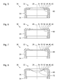
- FIG. 5 shows a schematic representation of a section through a further sealing device 30, which in some features, properties and functions of the basis of the FIGS. 1 to 4
- the sealing device shown is similar.
- the type of representation, in particular the sectional plane corresponds to that of FIGS. 2 to 4 and especially the FIG. 1 , wherein neither a tube nor a shaft of a medical instrument are indicated.
- FIG. 5 shown sealing device 30 from the basis of FIGS. 1 to 4 differs illustrated sealing device.
- the sealing lip 50 is arranged relative to the support region 40 further proximally (in the figures: above).
- the proximal surface of the sealing lip 50 is arranged flush with the proximal surface of the support region 40.
- the proximal surfaces of the sealing lip 50, the support region 40 and the transition region 60 thus lie in one plane.
- the transition region 60 has a conical distal surface.
- FIG. 6 shows a schematic representation of a section through another sealing device 30, which in some features, properties and functions based on the FIGS. 1 to 5 Similar to illustrated sealing devices.
- the type of representation corresponds to that of the FIGS. 1 to 4 and especially the FIG. 5 , Particular features, properties and functions are shown below, in which the in FIG. 6 shown sealing device from the basis of FIGS. 1 to 5 differs illustrated sealing devices.
- the sealing lip 50 is arranged relative to the support portion 40 so that neither the proximal surfaces nor the distal surfaces of the sealing lip 50 and the support portion 40 are flush or lie in a plane. Instead, the transition region 60 has conical surfaces both proximally and distally.
- FIG. 7 shows a schematic representation of a section through another sealing device 30, which in some features, properties and functions based on the FIGS. 1 to 6 Similar to illustrated sealing devices.
- the type of representation corresponds to that of the FIGS. 1 to 4 and especially the FIGS. 5 and 6 , Particular features, properties and functions are shown below, in which the in FIG. 7 shown sealing device from the basis of FIGS. 1 to 6 differs illustrated sealing devices.
- the proximal surface of the transition region 60 between the sealing lip 50 and support portion 40 is not conical, but more generally funnel-shaped, but with a rounded transition to the outer edge 52 of the sealing lip 50 is formed.
- the inner edge 44 of the support region 40 is defined by a sharp edge to the transition region 60.
- a soft transition to the transition region 60 may be provided on the inner edge 44 of the support region 40. Accordingly, the conical distal surfaces of the transition region 60 in the basis of Figures 5 and 60 embodiments shown to be rounded.
- FIG. 8 shows a schematic representation of a section through another sealing device 30, which in some features, properties and functions based on the FIGS. 1 to 7 Similar to illustrated sealing devices.
- the type of representation corresponds to that of the FIGS. 1 to 4 and especially the FIGS. 5 to 7 , Particular features, properties and functions are shown below, in which the in FIG. 8 shown sealing device from the basis of FIGS. 1 to 7 differs illustrated sealing devices.
- sealing device 30 differs from the basis of the FIGS. 1 to 7 Sealing devices shown in particular in that the sealing lip 50, the shape of an annular section of a cone or circular cone 72, the in FIG. 8 is indicated in dashed lines, has.
- the tip of the circular cone 72 points distally to facilitate insertion of a shaft of a medical instrument into the sealing device by a centering action.
- the outer edge 52 of the sealing lip 50 is disposed between two planes defined by the proximal and distal surfaces of the support portion 40. Therefore, both the proximal and the distal surfaces of the transition region 60 each have a conical shape similar to that of FIG FIG. 6 illustrated sealing device.
- the proximal surface of the sealing lip 50 is flush with the proximal surface of the transition region 60.
- the proximal surfaces of the sealing lip 50 and the transition region 60 enclose the same angle with the longitudinal axis 28 of a shaft inserted in the intended middle position and orientation in the sealing device 30.
- FIG. 9 shows a schematic representation of a section through another sealing device 30, which in some features, properties and functions based on the FIGS. 1 to 8 Similar to illustrated sealing devices.
- the type of representation corresponds to that of the FIGS. 1 to 4 and especially the FIGS. 5 to 8 , Particular features, properties and functions are shown below, in which the in FIG. 9 shown sealing device from the basis of FIGS. 1 to 8 differs illustrated sealing devices.
- sealing device 30 differs from the basis of the FIGS. 1 to 8 illustrated sealing devices in particular characterized in that the sealing lip 50 has no constant thickness. Rather, the thickness of the sealing lip 50 varies in the direction of its circumference.
- the proximal and distal surfaces of the sealing lip 50 are each flat, with the surface normals at an angle of approximately 1.5 Include degrees. Since the in FIG. 9 sectional plane shown is selected so that the surface normals of both surfaces of the sealing lip 50 lie in the cutting plane are in FIG. 9 (right) the minimum thickness and (left) the maximum thickness of the sealing lip 50 visible.
- FIG. 10 shows a schematic representation of a section through another sealing device 30, which in some features, properties and functions based on the FIGS. 1 to 9 Similar to illustrated sealing devices.
- the type of representation corresponds to that of the FIGS. 1 to 4 and especially the FIGS. 5 to 9 , Particular features, properties and functions are shown below, in which the in FIG. 10 shown sealing device from the basis of FIGS. 1 to 9 differs illustrated sealing devices.
- the sealing lip 50 has a width varying along its circumference.
- both the outer edge 52 and the inner edge 54 of the sealing lip 50 are each circular, wherein the centers of both edges 52, 54 are spaced from each other.
- the center of the inner edge 54 of the sealing lip 50 is located on the longitudinal axis 28 of a shaft inserted in the intended middle position and orientation in the sealing device 30.
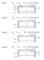
- FIG. 11 shows a schematic representation of a section through another sealing device 30, which in some features, properties and functions based on the FIGS. 1 to 10 Similar to illustrated sealing devices.
- the type of representation corresponds to that of the FIGS. 1 to 4 and especially the FIGS. 5 to 10 ,
- the following are features, properties and functions in which the in FIG. 11 shown sealing device from the basis of FIGS. 1 to 10 differs illustrated sealing devices.
- sealing device 30 differs from that of the FIG. 10 illustrated sealing device in particular in that the sealing lip 50 is not like at the basis of the Figures 5 and 10 Sealing devices shown flush with the proximal surface of the support portion 40, but similar to the reference to the FIGS. 1 to 4 . 7 and 9 shown sealing means is arranged flush with the distal surface of the support portion 40. Furthermore, the in FIG. 11 shown sealing device 30 from the basis of FIG. 10 illustrated in that the inner edge 54 of the sealing lip 50 is positioned eccentrically.
- the inner edge 44 of the support portion 40, the outer edge 52 and the inner edge 54 of the sealing lip 50 are each circular, wherein the centers of the inner edge 44 of the support portion 40 and the outer edge 52 of the sealing lip 50 on a in FIG. 11 Not shown symmetry axis of the sealing device 30 are.
- the center of the inner edge 54 of the sealing lip 50 and thus the longitudinal axis 28 of an inserted into the intended mean position and orientation in the sealing device 30 shaft are spaced from the symmetry axis of the sealing device 30.
- FIG. 12 shows a schematic representation of a section through another sealing device 30, which in some features, properties and functions based on the FIGS. 1 to 11 Similar to illustrated sealing devices.
- the type of representation corresponds to that of the FIGS. 1 to 4 and especially the FIGS. 5 to 11 , Particular features, properties and functions are shown below, in which the in FIG. 12 shown sealing device from the basis of FIGS. 1 to 11 differs illustrated sealing devices.
- sealing device 30 differs from the basis of the FIGS. 1 to 11 Sealing devices shown in particular in the embodiment of the inner edge 54 of the sealing lip 50.
- the inner edge 54 is indicated in each case with the shape of a narrow annular section of a lateral surface of a circular cylinder, wherein the axis of symmetry of the circular cylinder coincides with the longitudinal axis 28 of an inserted in the intended central position and orientation in the sealing device 30 shaft.
- the inner edge 54 of the sealing lip 50 has the shape of a narrow annular section of a lateral surface one in FIG.
- cylinder 78 whose axis of symmetry (ie direction of translational invariance) is not parallel to the longitudinal axis 28 of an inserted in the intended middle position and orientation in the sealing device 30 shaft of a medical instrument. Rather, the symmetry axis of the cylinder 78 and the longitudinal axis 28 enclose an angle, for example, in the range of 15 degrees to 45 degrees, and in particular is about 30 degrees.
- FIG. 13 shows a schematic representation of a section through another sealing device 30, which in some features, properties and functions based on the FIGS. 1 to 12 Similar to illustrated sealing devices.
- the type of representation corresponds to that of the FIGS. 1 to 4 and especially the FIGS. 5 to 12 , Particular features, properties and functions are shown below, in which the in FIG. 13 shown sealing device from the basis of FIGS. 1 to 12 differs illustrated sealing devices.
- sealing device 30 differs from the basis of the FIGS. 1 to 12 in particular characterized in that the sealing lip 50 is not parallel to a plane orthogonal to the longitudinal axis 28 of an inserted in the intended middle position and orientation in the sealing device 30 shaft.
- the sealing lip 50 is instead tilted.
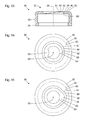
- FIG. 14 shows a schematic plan view of a sealing device 30, which in some features, properties and functions based on the FIGS. 1 to 13 Similar to illustrated sealing devices.
- the drawing plane of the FIG. 14 is orthogonal to the cutting planes of the FIGS. 1 to 13 and to the longitudinal axis 28 of an inserted in the intended middle position and orientation in the sealing device 30 shaft.
- the sealing device 30 is shown in a proximal view, so that the proximal side 32 (see FIG. FIGS. 1 to 13 ) is visible.
- the contour of the inner surface of the cylindrical wall 38 of the sealing device 30 is indicated by a dashed line.
- the cylindrical wall 38 of the sealing device 30 has the shape of a section of a lateral surface of a circular cylinder, the contours of its cross section are therefore each circular.
- the inner edge 44 of the support portion 40 and the outer edge 52 of the sealing lip 50 are each circular, with all the circle centers are on the longitudinal axis 28 of an inserted in the intended middle position and orientation in the sealing device 30 shaft.
- a tongue 56 is provided on the sealing lip 50, which protrudes into the opening enclosed by the sealing lip 50 for a shaft.
- the inner edge 54 of the sealing lip 50 therefore has a shape which deviates in the region of the tongue 56 from a pure circular shape.
- FIG. 15 shows a schematic representation of a plan view of another sealing device 30, which in some features, properties and functions based on the FIGS. 1 to 14 Similar to illustrated sealing devices.
- the type of representation corresponds to that of the FIG. 14 , Particular features, properties and functions are described below, in which the in FIG. 15 shown sealing device 30 from the basis of FIGS. 1 to 14 differs illustrated sealing devices.
- the sealing lip 50 has a broadened like area 58 area.
- the outer edge 52 of the sealing lip 50 and the inner edge 44 of the support portion 40 have on or adjacent to the book-like widened portion 58 of the sealing lip on a shape deviating from a circular shape.
- the inner edge 54 of the sealing lip 50 is circular.
- FIG. 16 shows a schematic representation of a plan view of another sealing device 30, which in some features, properties and functions based on the FIGS. 1 to 15 Similar to illustrated sealing devices.
- the type of representation corresponds to that of the FIGS. 14 and 15 ,
- the following describes characteristics, properties and functions in which the in FIG. 16 shown sealing device 30 from the basis of FIGS. 1 to 15 differs illustrated sealing devices.
- the inner edge 44 of the support portion 40, the outer edge 52 and the inner edge 54 of the sealing lip 50 each have the shape of a circle, wherein the centers of the inner edge 44 of the support portion 40 and the outer edge 52 of the sealing lip 50 opposite the symmetry axis of other features of the sealing device 30 and in particular with respect to the center of the inner edge 54 of the sealing lip 50 are shifted.
- the sealing lip 50 therefore has similar to the reference to the FIGS. 10, 11 . 14 and 15 illustrated sealing means on a varying width along its circumference.
- FIG. 17 shows a schematic representation of a plan view of another sealing device 30, which in some features, properties and functions based on the FIGS. 1 to 16 Similar to illustrated sealing devices.
- the type of representation corresponds to that of the FIGS. 14 to 16 ,
- the following describes characteristics, properties and functions in which the in FIG. 17 shown sealing device 30 from the basis of FIGS. 1 to 16 differs illustrated sealing devices.
- the inner edge 44 of the support portion 40, the outer edge 52 and the inner edge 54 of the sealing lip 50 each have the shape of an ellipse, wherein the surface centers of the ellipses on the axis of symmetry of other features of the sealing device 30 and the longitudinal axis 28 of an in the intended mean position and orientation in the sealing device 30 inserted stem lie.
- the major major axes of the elliptical inner edge 44 of the support portion 40 and the elliptical outer edge 52 of the sealing lip 50 are parallel to the minor major axis of the elliptical inner edge 54 of the sealing lip 50 and the minor major axes of the elliptical inner edge 44 of the support portion 40 and the elliptical outer edge 52 of the sealing lip 50 parallel to the major axis of the elliptical inner edge 54 of the sealing lip 50.
- the sealing lip 50 therefore has a continuously varying width along its circumference.
- FIG. 18 shows a schematic representation of a section through another sealing device 30, which in some features, properties and functions based on the FIGS. 1 to 17 Similar to illustrated sealing devices.
- the type of representation corresponds that of the FIGS. 1 to 4 and especially the FIGS. 5 to 13 , Particular features, properties and functions are shown below, in which the in FIG. 18 shown sealing device from the basis of FIGS. 1 to 17 differs illustrated sealing devices.
- FIG. 18 shown sealing device 30 differs from the basis of the FIGS. 1 to 12 in particular characterized in that the sealing lip 50 is not parallel to a plane orthogonal to the longitudinal axis 28 of an inserted in the intended middle position and orientation in the sealing device 30 shaft. This resembles the in FIG. 18 shown sealing device 30 of the basis of FIG. 13 illustrated sealing device.
- the support region 40 is not arranged in a plane orthogonal to the longitudinal axis 28 of a shaft inserted in the intended middle position and orientation in the sealing device 30. Rather, both the support portion 40 and the sealing lip 50 are parallel or substantially parallel to a plane which is tilted relative to the longitudinal axis 28, respectively.
- the normal of a plane to which the support portion 40 and the sealing lip 50 are parallel or substantially parallel encloses an angle in the range of 5 with the longitudinal axis 28 of a shank inserted into the intended middle position and orientation in the sealing means 30 Degrees to 10 degrees. However, the angle may alternatively be less than 5 degrees or greater than 10 degrees.
- the support areas are each formed as annular cutouts of flat plates.
- the support areas thus each have a flat or substantially planar proximal surface area and a flat and substantially planar distal surface area, which are parallel to each other.
- the entire support areas or the proximal surface areas and / or the distal surface areas of the Support areas each having the shape of annular cutouts of curved surfaces, for example, of spherical surfaces or surface of other ellipsoids of revolution.
- each of the illustrated sealing devices 30 can consist of a plurality of different materials, wherein regions of different materials are in particular materially and / or positively connected with each other.
- the sealing lip of a comparatively soft material and the support region or a part of the support region or the cylindrical wall 38 are formed of a comparatively hard material.
- the sealing lips 50 are each not rotationally symmetrical to the longitudinal axis 28 of an inserted in the intended middle position and orientation in the sealing device 30 shaft.
- the deformation of the sealing lip 50 by a shaft inserted into the sealing device 30 - similar to the FIG. 2 Therefore, causes an elastic deformation and an associated mechanical stress within the sealing lip 50 and a contact pressure of the sealing lip 50 on the outer surface of the shaft, which are not rotationally symmetrical, but vary along the circumference of the sealing lip 50.
- a gradual instead of a sudden and simultaneous folding or folding over of the sealing lip 50 may be favored.
- a gradual turning of the sealing lip 50 is - among other things depending on the friction between the sealing lip 50 and the outer surface of the shaft - for example, from the point at which the sealing lip 50 has the greatest width or the smallest thickness and spreads from this location starting along the circumference of the sealing lip until the sealing lip 50 completely is turned down.
- the gradual flipping of the sealing lip 50 is less noticeable and is perceived by medical personnel as less disturbing.
- the entire surface or part of the surface of the sealing lip 40 may be coated with poly (p-xylylene), which is also marketed under the trade name Parylene.
- a friction-reducing coating can reduce static friction and / or sliding friction between the sealing device 30 and a medical instrument inserted into the sealing device 30.
- FIGS. 1 to 18 shown sealing devices Characteristics of the basis of the FIGS. 1 to 18 shown sealing devices are partially combined with each other.
- the sealing lips and the transition areas similar to those based on the FIGS. 5 to 8 be arranged and formed sealing means shown.
- an asymmetrical configuration of the sealing lip 50 may be similar to that described with reference to FIGS FIGS. 9 to 18 shown present when sealing lip 50 and support portion 40 are not clearly distinguishable from each other, but for example, with a common wedge-shaped cross-section continuously merge into each other.
Landscapes
- Health & Medical Sciences (AREA)
- Life Sciences & Earth Sciences (AREA)
- Surgery (AREA)
- Engineering & Computer Science (AREA)
- Medical Informatics (AREA)
- Nuclear Medicine, Radiotherapy & Molecular Imaging (AREA)
- Biomedical Technology (AREA)
- Heart & Thoracic Surgery (AREA)
- Pathology (AREA)
- Molecular Biology (AREA)
- Animal Behavior & Ethology (AREA)
- General Health & Medical Sciences (AREA)
- Public Health (AREA)
- Veterinary Medicine (AREA)
- General Engineering & Computer Science (AREA)
- Mechanical Engineering (AREA)
- Surgical Instruments (AREA)
Abstract
Description
- Die vorliegende Erfindung ist auf eine Dichteinrichtung zur Abdichtung einer Durchführung für ein medizinisches Instrument, insbesondere zur Abdichtung des Zwischenraums zwischen einem Tubus und einem während eines mikroinvasiven medizinischen Eingriffs in dem Tubus angeordneten Schafts eines medizinischen Instruments, gerichtet.
- Ein Beispiel für mikroinvasive medizinische Methoden ist die Laparoskopie. Mittels eines Trokars wird ein künstlicher Zugang zur Bauchhöhle eines Patienten durch dessen Bauchdecke hindurch geschaffen. Durch das Lumen eines während des laparoskopischen Eingriffs in der Bauchdecke verbleibenden Tubus des Trokars können ein Endoskop und/oder weitere medizinische Instrumente (beispielsweise Zangen, Scheren, Nadelhalter) in die Bauchhöhle eingeführt werden. Während der Laparoskopie wird der Bauchraum mit Kohlenstoffdioxid oder einem anderen Gas gefüllt, um ein Pneumoperitoneum, einen den medizinischen Eingriff ermöglichenden Hohlraum, zu schaffen. Ohne besondere Maßnahmen würde dieses Gas durch den Tubus entweichen. Deshalb wurden zahlreiche Ansätze entwickelt, um das Lumen des Tubus eines Trokars möglichst fluiddicht zu verschließen, und zwar sowohl im leeren Zustand als auch bei eingeführtem Instrument.
- Teilweise ähnliche Aufgabestellungen können sich an einem Arbeitskanal eines Endoskops oder beim Einführen eines Katheters in ein Blutgefäß ergeben. Im letztgenannten Fall ist jedoch nicht das Entweichen eines Gases, sondern von Blut zu verhindern.
- In
US 4,857,062 ist ein Ventil zum Einführen eines Katheters in eine Arterie beschrieben. Zur Abdichtung ist ein flexibles Element vorgesehen, das zur Ausbildung einer fluiddichten Abdichtung mit einem Katheter komprimiert ist. - In
WO 93/01850 A1 - In
US 5,366,446 ist eine Einführanordnung zur Verwendung auf der Haut eines Patienten beschrieben, die für das Einführen von Tuben mit unterschiedlichen Außendurchmessern ausgebildet ist. Die Anordnung umfasst eine Membran aus einem durchstechbaren elastomeren Material in der Mitte eines Faltenbalgs. - In
EP 0 746 359 B1 ist ein Katheter-Sperrventil beschrieben. Zur Abdichtung sind eine Gummidichtung mit einer Öffnung und distal dieser ein Entenschnabelventil mit einem geraden Schlitz vorgesehen. - In
US 4,430,081 ist eine Kanüle zur Verwendung mit Angiographiekathetern beschrieben. Zur Abdichtung gegen das Eindringen von Luft oder das Austreten von Blut aus einem Blutgefäß sind eine erste Dichtung mit einem Schlitz, eine zweite Dichtung mit einem Loch und eine dritte Dichtung mit einer Klappe darin vorgesehen, die aneinander angrenzend angeordnet sind. - In
WO 91/12838 A1 - In
WO 98/32484 A1 - Dichtscheibe aus weich-elastischem Schaumkunststoff mit radial verlaufenden Schlitzen vorgesehen ist.
- In
US 6,551,282 B1 ist eine Dichtung zur Abdichtung eines Tubus bei eingeführtem Schaft eines Endoskops beschrieben. Eine breite ringförmige Dichtung ist von einem steiferen Ring umgeben. - Die beschriebenen Dichteinrichtungen weisen jeweils spezifische Vor- und Nachteile auf. Eine sehr weitgehende und zuverlässige Dichtwirkung ist ohne Weiteres mit einer Dichtlippe erzielbar, die mit einem möglichst hohen Anpressdruck gegen die äußere Oberfläche eines Schafts eines Instruments drückt. Dabei entsteht jedoch hohe Gleit- und Haftreibung. Eine dünne und/oder weiche Dichtlippe erzeugt nur geringe Gleit- und Haftreibung, ist aber nicht nur weniger robust, sondern weist bei einer seitlichen Verschiebung des Schafts in der Dichteinrichtung eine reduzierte Wirkung auf.
- Bei allen bekannten dünnen und weichen Dichtlippen ist bei einer Änderung der Richtung der Bewegung eines Schafts in der Dichteinrichtung ein Umlegen der Dichtlippe zu beobachten, das mit einer fühlbaren Änderung der zwischen Schaft und Dichteinrichtung wirkenden Kraft einher geht. Diese Änderung der Kraft kann eine unwillkürliche oder dem Willen des medizinischen Personals nicht genau entsprechende Bewegung des Schafts bewirken, die als störend empfunden wird oder sogar den Patienten gefährden kann.
- Eine Aufgabe der vorliegenden Erfindung besteht darin, eine verbesserte Dichteinrichtung zu schaffen, die insbesondere die aufgezählten Anforderungen und Erwartungen in ausgewogenen Verhältnissen erfüllt.
- Diese Aufgabe wird durch die Gegenstände der unabhängigen Ansprüche gelöst.
- Weiterbildungen sind in den abhängigen Ansprüchen angegeben.
- Viele herkömmliche Dichteinrichtungen weisen möglichst breite Dichtlippen auf, um einer Bewegung eines Schafts eines Instruments in der Dichteinrichtung in einer Richtung orthogonal zur Längsachse des Schafts einen geringen Widerstand entgegenzusetzen, und um eine Verwendbarkeit mit Schäften mit unterschiedlichen Durchmessern zu ermöglichen. Ferner beruhte die Verwendung breiter Dichtlippen auf der Annahme, dass diese aufgrund ihrer großen Elastizität einer axialen Bewegung eines Schafts relativ zur Dichteinrichtung nur einen geringen Widerstand entgegensetzt. Die vorliegende Erfindung beruht auf der Erkenntnis, dass die breiten Dichtlippen weniger eine Lösung bieten als ein Problem schaffen. Breite Dichtlippen müssen eine bestimmte Mindestwandstärke aufweisen, um beispielsweise durch den Überdruck im Pneumoperitoneum nicht aufgeblasen oder verformt zu werden. Eine Verwendbarkeit für viele verschiedene Schaftdurchmesser hat dann zwangsläufig eine große mechanische Spannung bei einem großen Schaftdurchmesser zur Folge, die wiederum die Reibung erhöht.
- Im Übrigen ist eine Bewegbarkeit eines Schafts relativ zur Dichteinrichtung in einer Richtung orthogonal zur Längsachse des Schafts nicht nur durch breite und elastische Dichtlippen erzielbar. In der bereits erwähnten
US 6,551,282 B1 ist zwar denFiguren 4 und5 entnehmbar, dass die genannte Bewegbarkeit auch durch andere Teile der Dichteinrichtung gewährleistet werden kann. Ähnliches gilt fürUS 7,803,135 B2 . Es ist jedoch bei beiden Druckschriften nicht erkennbar, ob die genannte Erkenntnis vorlag. Jedenfalls sind die Autoren derUS 6,551,282 B1 vom Grundansatz breiter Dichtlippen nicht abgewichen. Die Autoren derUS 7,803,135 B2 haben erkennbar einen Weg beschritten, der vom nachfolgend beschriebenen Lösungsansatz weg führt. - Ausführungsformen der vorliegenden Erfindung beruhen auf der Idee, eine Verschiebbarkeit eines Schafts in einer Dichteinrichtung in einer Richtung orthogonal zur Längsachse des Schafts nicht mittels der Dichtlippe zu ermöglichen, sondern die Dichtlippe vergleichsweise schmal auszugestalten. Die genannte Verschiebbarkeit muss dann zwar durch andere Maßnahmen gewährleistet sein, die Dichtlippe kann aber ohne die Gefahr einer Verformung durch eine Druckdifferenz vergleichsweise dünn ausgeführt werden. Durch einen die Dichtlippe umgebenden Stützbereich mit vergleichsweise geringer Elastizität einerseits und eine präzise Anpassung der Dichtlippe an einen vorbestimmten Schaftdurchmesser können eine zuverlässige Dichtwirkung und gleichzeitig geringe Reibung und eine nur geringe Kraftvariation beim Umlegen der Dichtlippe nach Richtungsänderung erzielt werden.
- Ausführungsformen der vorliegenden Erfindung beruhen ferner auf der Erkenntnis, dass das Umlegen der Dichtlippe nach Richtungsänderung der Bewegung eines Schafts in der Dichteinrichtung dann besonders spürbar und störend ist, wenn es entlang des gesamten Umfangs der Dichtlippe gleichzeitig stattfindet, und dass dies durch die übliche rotationssymmetrische Ausgestaltung von Dichteinrichtungen und ihren Dichtlippen begünstigt wird. Ausführungsformen der vorliegenden Erfindung beruhen deshalb auf der Idee, die Rotationssymmetrie der Dichtlippe zu brechen, um ein nicht gleichzeitiges, sondern allmähliches Umlegen der Dichtlippe - ausgehend von einem Punkt und sich entlang ihres Umfangs ausbreitend - zu begünstigen.
- Eine Dichteinrichtung zur Abdichtung einer Durchführung für einen Schaft eines medizinischen Instruments umfasst einen Befestigungsbereich zur Befestigung der Dichteinrichtung an einem Tubus oder einer anderen medizinischen Vorrichtung, einen ringartigen Stützbereich, der mit dem Befestigungsbereich verbunden ist, und eine ringartige Dichtlippe mit einem äußeren Rand, der mit einem inneren Rand des Stützbereichs verbunden ist, und einem inneren Rand, der vorgesehen und ausgebildet ist, um an einer äußeren Oberfläche eines in die Dichteinrichtung eingeführten Schafts fluiddicht anzuliegen, wobei die Differenz U2 - US des Umfangs U2 des inneren Rands des Stützbereichs und des Umfangs US eines Schafts eines medizinischen Instruments, für den die Dichteinrichtung vorgesehen und ausgebildet ist, nicht größer ist als die Differenz US - U1 des Umfangs US des Schafts und des Umfangs U1 des inneren Rands der Dichtlippe in ihrem spannungsfreien Zustand (U2 - US ≤ US - U1) oder die Differenz D2 - DS des mittleren Durchmessers D2 des inneren Rands des Stützbereichs und des mittleren Durchmessers DS eines Schafts eines medizinischen Instruments, für den die Dichteinrichtung vorgesehen und ausgebildet ist, nicht größer ist als die Differenz DS - D1 des mittleren Durchmessers DS des Schafts und des mittleren Durchmessers D1 des inneren Rands der Dichtlippe D2 - DS ≤ DS - D1.
- Die genannte Bedingung für die Umfänge kann alternativ so formuliert werden, dass der arithmetische Mittelwert (U1 + U2)/2 des Umfangs U1 des inneren Rands der Dichtlippe und des Umfangs U2 des inneren Rands des Stützbereichs nicht größer ist als der Umfang US eines Schafts eines medizinischen Instruments, für den die Dichteinrichtung vorgesehen und ausgebildet ist ((U1 + U2)/2 ≤ DS). Die genannte Bedingung für die mittleren Durchmesser kann alternativ so formuliert werden dass der arithmetische Mittelwert (D1 + D2)/2 des mittleren Durchmessers D1 des inneren Rands der Dichtlippe und des mittleren Durchmessers D2 des inneren Rands des Stützbereichs nicht größer ist als der mittlere Durchmesser DS eines Schafts eines medizinischen Instruments, für den die Dichteinrichtung vorgesehen und ausgebildet ist.
- Eine Dichteinrichtung zur Abdichtung einer Durchführung für einen Schaft eines medizinischen Instruments umfasst einen Befestigungsbereich zur Befestigung der Dichteinrichtung an einem Tubus oder einer anderen medizinischen Vorrichtung, einen ringartigen Stützbereich, der mit dem Befestigungsbereich verbunden ist, und eine ringartige Dichtlippe mit einem äußeren Rand, der mit einem inneren Rand des Stützbereichs verbunden ist, und einem inneren Rand, der vorgesehen und ausgebildet ist, um an einer äußeren Oberfläche eines in die Dichteinrichtung eingeführten Schafts fluiddicht anzuliegen, wobei der Umfang des inneren Rands der Dichtlippe mindestens sechs Zehntel und höchstens neun Zehntel des Umfangs eines Schafts eines medizinischen Instruments, für den die Dichteinrichtung vorgesehen und ausgebildet ist, beträgt
- Eine Dichteinrichtung zur Abdichtung einer Durchführung für einen Schaft eines medizinischen Instruments umfasst einen Befestigungsbereich zur Befestigung der Dichteinrichtung an einem Tubus oder einer anderen medizinischen Vorrichtung, einen ringartigen Stützbereich, der mit dem Befestigungsbereich verbunden ist, und eine ringartige Dichtlippe mit einem äußeren Rand, der mit einem inneren Rand des Stützbereichs verbunden ist, und einem inneren Rand, der vorgesehen und ausgebildet ist, um an einer äußeren Oberfläche eines in die Dichteinrichtung eingeführten Schafts fluiddicht anzuliegen, wobei die mittlere Dicke der Dichtlippe insbesondere höchstens ein Fünftel der mittleren Dicke des Stützbereichs beträgt.
- Bei den hier beschriebenen Dichteinrichtungen ist die Dichtlippe jeweils insbesondere membranartig. Insbesondere weist die Dichtlippe eine konstante Dicke oder eine in radialer Richtung und/oder in umfänglicher Richtung jeweils nur geringfügig (insbesondere um einen Faktor zwei oder weniger) variierende Dicke auf.
- Soweit die inneren Ränder des Stützbereichs und der Dichtlippe und die äußere Kontur des Querschnitts des Schafts eines medizinischen Instruments, für den die Dichteinrichtung vorgesehen und ausgebildet ist, jeweils kreisförmig sind, sind die mittleren Durchmesser die Durchmesser und die Bedingungen für die Umfänge und die Durchmesser äquivalent. Als mittlerer Durchmesser eines Rands, der nur in Abschnitten, die zusammen weniger als die Hälfte oder weniger als ein Drittel des Umfangs des Rands ausmachen, von der Gestalt eines Kreises abweicht, wird der Durchmesser des Kreises angesehen. Als mittlerer Durchmesser eines anderen nicht kreisförmigen Rands wird der Durchmesser eines Kreises, dessen Flächeninhalt dem Inhalt der von dem Rand begrenzten Fläche entspricht, angesehen.
- Wenn der Stützbereich und die Dichtlippe das gleiche Material aufweisen und einstückig ausgebildet sind und zwischen dem Stützbereich und der Dichtlippe keine stufenförmige Änderung der Dicke vorliegt, ist der innere Rand des Stützbereichs die (linienförmige) Menge der Orte, an denen die Kraft, die die Dichteinrichtung einer Verformung durch einen Schaft eines medizinischen Instruments, für den die Dichteinrichtung vorgesehen und ausgebildet ist, entgegensetzt, stark ansteigt. Der innere Rand des Stützbereichs ist beispielsweise die (linienförmige) Menge der Orte, an denen die Kraft, die die Dichteinrichtung einer Verformung durch einen Schaft eines medizinischen Instruments, für den die Dichteinrichtung vorgesehen und ausgebildet ist, entgegensetzt, gegenüber dem minimalen Wert verdoppelt oder verdreifacht oder verfünffacht oder verzehnfacht ist. Der innere Rand des Stützbereichs ist insbesondere die Linie, an der die Dicke der Dichteinrichtung dem arithmetischen Mittelwert der minimalen Dicke der Dichtlippe und der maximalen Dicke des Stützbereichs oder 90 % der Dicke des Stützbereichs entspricht. Wenn der Stützbereich die Gestalt eines ringartigen Ausschnitts einer Platte mit konstanter Dicke aufweist und kontinuierlich in die Dichtlippe übergeht, ist der innere Rand des Stützbereichs insbesondere der innere Rand des plattenförmigen Bereichs konstanter Dicke. Der äußere Rand des Stützbereichs liegt beispielsweise dort, wo der Stützbereich in eine im Wesentlichen zylindrische Wand oder unmittelbar in einen Befestigungsbereich übergeht.
- Die Dichteinrichtung ist insbesondere zur Abdichtung des ringförmigen oder ringartigen Zwischenraums zwischen der inneren Oberfläche eines Tubus eines Trokars und der äußeren Oberfläche eines im Tubus angeordneten Schafts eines medizinischen Instruments vorgesehen. Das medizinische Instrument ist beispielsweise ein Endoskop oder ein anderes medizinisches Instrument zur Verwendung bei mikroinvasiven medizinischen Maßnahmen. Die Dichteinrichtung ist für ein medizinisches Instrument mit einem Schaft mit einem vorbestimmten Querschnitt, insbesondere mit einem kreisförmigen Querschnitt mit einem vorbestimmten Durchmesser, vorgesehen und ausgebildet. Um eine Verwechslung oder eine unbeabsichtigte Verwendung für einen Schaftquerschnitt, für den die Dichteinrichtung nicht vorgesehen und ausgebildet ist, zu vermeiden, kann die Dichteinrichtung mit einer alphanumerischen Beschriftung, einem Symbol oder einer Farbe eindeutig gekennzeichnet sein. Insbesondere kann der Schaftdurchmesser, für den die Dichteinrichtung vorgesehen und ausgebildet ist, an der Dichteinrichtung alphanumerisch angegeben sein.
- Der Stützbereich und die Dichtlippe können das gleiche Material aufweisen, insbesondere ist die gesamte Dichteinrichtung einstückig ausgebildet, beispielsweise als Gussteil, das den Befestigungsbereich, den Stützbereich und die Dichtlippe umfasst. Alternativ können die Dichtlippe einerseits und der Stützbereich und/oder der Befestigungsbereich andererseits unterschiedliche Materialien aufweisen, wobei Bereiche aus unterschiedlichen Materialien insbesondere stoff- und/oder formschlüssig miteinander verbunden sind. Beispielsweise sind die Dichtlippe aus einem vergleichsweise weichen Material und der Stützbereich oder ein Teil des Stützbereichs oder die zylindrische Wand 38 aus einem vergleichsweise harten Material gebildet.
- Der Befestigungsbereich umfasst beispielsweise einen nach innen ragenden Kragen am distalen bzw. dem Patienten und dem Tubus zuzuwendenden Rand, der eine formschlüssige mechanische Verbindung mit einer Nut am proximalen bzw. der Dichteinrichtung zuzuwendenden Rand eines Tubus oder einer anderen medizinischen Vorrichtung bilden kann.
- Die Dichteinrichtung ist insbesondere teilweise oder vollständig aus einem Silikonelastomer, einem anderen Elastomer oder einem anderen elastischen Material gebildet. Das Material der Dichteinrichtung oder zumindest das Material der Dichtlippe weist insbesondere eine Härte von ca. 40 Shore A auf. Die Elastizität des Materials, insbesondere im Befestigungsbereich kann das Bilden und das Lösen einer formschlüssigen mechanischen Verbindung der Dichteinrichtung mit einem Tubus oder einer anderen medizinischen Vorrichtung ermöglichen.
- Ein Stützbereich oder eine Dichtlippe ist ringartig, wenn der Stützbereich bzw. die Dichtlippe die Topologie eines Kreisrings aufweist, also im mathematischen Sinne zweifach zusammenhängend ist. Weder der ringartige Stützbereich noch die ringartige Dichtlippe muss kreisringförmig sein. Die inneren und äußeren Ränder des Stützbereichs und der Dichtlippe können jeweils kreisförmig, elliptisch, oval, polygonal sein oder eine andere Gestalt aufweisen.
- Eine Dichteinrichtung mit den beschriebenen Merkmalen kann eine sehr schmale Dichtlippe, also eine Dichtlippe, bei der die Differenz der Durchmesser oder die Differenz der Umfänge des äußeren und des inneren Rands klein ist, aufweisen, ohne bei einer seitlichen Verschiebung eines in die Dichteinrichtung eingeführten Schafts eine Aufhebung der Dichtwirkung zu bewirken. Eine schmale Dichtlippe kann wiederum besonders dünnwandig und besonders elastisch ausgebildet sein, ohne die Dichtwirkung zu beeinträchtigen. Eine dünnwandige und elastische Ausgestaltung der Dichtlippe kann die Reibung zwischen der Dichtlippe und einem Schaft reduzieren und die Auswirkung des Umlegens der Dichtlippe bei Umkehrung der Bewegungsrichtung eines Schafts in der Dichtrichtung minimieren.
- Bei einer Dichteinrichtung, wie sie hier beschrieben ist, ist die Dichtlippe insbesondere nicht rotationssymmetrisch zur Längsachse eines in der vorgesehenen mittleren Position und Orientierung in die Dichteinrichtung eingeführten Schafts.
- Eine Dichteinrichtung zur Abdichtung einer Durchführung für einen Schaft eines medizinischen Instruments umfasst einen Befestigungsbereich zur Befestigung der Dichteinrichtung an einem Tubus oder einer anderen medizinischen Vorrichtung und eine ringartige Dichtlippe mit einem inneren Rand, der vorgesehen und ausgebildet ist, um an einer äußeren Oberfläche eines in die Dichteinrichtung eingeführten Schafts fluiddicht anzuliegen, wobei die Dichtlippe nicht rotationssymmetrisch zur Längsachse eines in der vorgesehenen mittleren Position und Orientierung in die Dichteinrichtung eingeführten Schafts ist.
- Die Längsachse eines Schafts ist im Fall eines Schafts mit gerader und kreiszylindrischer Oberfläche die Symmetrieachse dieser Oberfläche. Die vorgesehene mittlere Position und Orientierung eines Schafts in der Dichteinrichtung ergibt sich aus der Geometrie der Dichteinrichtung. Beispielsweise ist der distale Rand und/oder die Befestigungseinrichtung nahe dem distalen Rand der Dichteinrichtung rotationssymmetrisch zur Längsachse eines in der vorgesehenen mittleren Position und Orientierung in die Dichteinrichtung eingeführten Schafts. Ferner sind die Position und die Orientierung der Längsachse eines in der vorgesehenen mittleren Position und Orientierung in die Dichteinrichtung eingeführten Schafts in der Regel durch den Tubus bzw. die medizinische Vorrichtung (insbesondere dessen bzw. deren Symmetrieachse) vorbestimmt, für den bzw. die die Dichteinrichtung vorgesehen und ausgebildet ist.
- Alternativ dazu, dass die Dichtlippe nicht rotationssymmetrisch zur Längsachse eines in der vorgesehenen mittleren Position und Orientierung in die Dichteinrichtung eingeführten Schafts ist, kann die Dichtlippe nicht rotationssymmetrisch zur Längsachse eines in die Dichteinrichtung eingeführten Schafts beim mechanischen spannungsärmsten Zustand der Dichteinrichtung sein.
- Eine nicht rotationssymmetrische Ausgestaltung der Dichtlippe kann zur Folge haben, dass in der Dichtlippe vorliegende Kräfte und mechanische Spannungen und zwischen der Dichtlippe (insbesondere ihrem inneren Rand) und einer äußeren Oberfläche eines Schafts wirkende Kräfte entlang des inneren Rands der Dichtlippe variieren. Dies wiederum kann bei einer Umkehr der Richtung, in der ein Schaft in der Dichteinrichtung bewegt wird, ein allmähliches, von einem Ort am inneren Rand der Dichtlippe ausgehendes und sich von dort vergleichsweise langsam ausbreitendes Umlegen der Dichtlippe bewirken. Die Wirkung des Umlegens, das von Anwendern herkömmlicher Dichteinrichtungen auch als Umschnappen bezeichnet wird, kann damit deutlich reduziert werden. Dies kann ein feinfühligeres Bewegen eines Schafts eines medizinischen Instruments in der Dichteinrichtung ermöglichen und das Risiko einer unwillkürlichen oder dem Willen des medizinischen Personals nicht genau entsprechenden Bewegung eines Schafts in der Dichteinrichtung und einer resultierenden Schädigung eines Patienten reduzieren.
- Eine Dichteinrichtung, wie sie hier beschrieben ist, umfasst insbesondere ferner einen ringartigen Stützbereich, der mit dem Befestigungsbereich verbunden ist, wobei ein äußerer Rand der Dichtlippe mit dem inneren Rand des Stützbereichs verbunden ist.
- Bei einer Dichteinrichtung, wie sie hier beschrieben ist, ist insbesondere zumindest entweder der innere Rand oder der äußere Rand der Dichtlippe nicht kreisförmig.
- Bei einer Dichteinrichtung, wie sie hier beschrieben ist, ist insbesondere der Flächenmittelpunkt der durch den inneren Rand der Dichtlippe begrenzten Fläche vom Flächenmittelpunkt der durch den äußeren Rand der Dichtlippe begrenzten Fläche beabstandet.
- Bei einer Dichteinrichtung, wie sie hier beschrieben ist, weist die Dichtlippe insbesondere im mechanisch spannungsfreien Zustand eine in Richtung ihres Umfangs variierende Dicke auf.
- Bei einer Dichteinrichtung, wie sie hier beschrieben ist, sind insbesondere die Flächennormalen zweier voneinander abgewandter Oberflächen der Dichtlippe an einander gegenüberliegenden Orten an den Oberflächen im mechanisch spannungsfreien Zustand der Dichtlippe nicht parallel.
- Die Flächennormalen zweier voneinander abgewandter Oberflächen der Dichtlippe an einander gegenüberliegenden Orten an den Oberflächen schließen insbesondere einen Winkel im Bereich von 1 Grad bis 3 Grad oder im Bereich von 1,5 Grad bis 2 Grad ein. Die beschriebene Nicht-Parallelität der Flächennormalen liegt insbesondere für die gesamte Fläche der Dichtlippe oder für mindestens die Hälfte der Fläche der Dichtlippe vor.
- Bei einer Dichteinrichtung, wie sie hier beschrieben ist, weist der innere Rand der Dichtlippe insbesondere die Gestalt eines Ausschnitts einer Mantelfläche eines Zylinders, dessen Symmetrieachse nicht parallel zur mittleren Flächennormalen zweier voneinander abgewandter Oberflächen der Dichtlippe ist, auf.
- Der innere Rand der Dichtlippe weist insbesondere die Gestalt eines Ausschnitts einer Mantelfläche eines schiefen Kreiszylinders oder eines anderen Zylinders auf. Die Symmetrieachse, d.h. die Richtung der Translationsinvarianz der Mantelfläche des Zylinders, schließt mit der mittleren Flächennormale zweier voneinander abgewandter Oberflächen insbesondere einen Winkel von mindestens 5 Grad oder mindestens 10 Grad oder mindestens 20 Grad oder mindestens 30 Grad ein. Die mittlere Flächennormale ist insbesondere der Mittelwert oder die halbe Differenz der normierten Integrale der Flächennormalen über die beiden voneinander abgewandten Oberflächen der Dichtlippe.
- Bei einer Dichteinrichtung, wie sie hier beschrieben ist, ist der innere Rand der Dichtlippe insbesondere abgerundet, beispielsweise mit einem kreisbogenförmigen Querschnitt.
- Bei einer Dichteinrichtung, wie sie hier beschrieben ist, weist die Dichtlippe insbesondere eine vom inneren Rand der Dichtlippe nach außen kontinuierlich ansteigende Dicke auf.
- Bei einer Dichteinrichtung, wie sie hier beschrieben ist, ist die mittlere Flächennormale der Dichtlippe insbesondere nicht parallel zur Längsachse eines in der vorgesehenen mittleren Position und Orientierung in die Dichteinrichtung eingeführten Schafts.
- Die mittlere Flächennormale der Dichtlippe ist insbesondere das normierte Integral der Flächennormalen von einer von zwei voneinander abgewandten Oberflächen der Dichtlippe über die gesamte Dichtlippe. Alternativ ist die mittlere Flächennormale beispielsweise der Mittelwert oder die halbe Differenz der normierten Integrale der Flächennormalen über die beiden voneinander abgewandten Oberflächen der Dichtlippe. Der Winkel zwischen der mittleren Flächennormalen und der Längsachse eines in der vorgesehenen mittleren Position und Orientierung in die Dichteinrichtung eingeführten Schafts beträgt insbesondere mindestens 5 Grad oder mindestens 10 Grad oder mindestens 20 Grad oder mindestens 30 Grad.
- Bei einer Dichteinrichtung, wie sie hier beschrieben ist, ist der Stützbereich insbesondere parallel oder im Wesentlichen parallel zu einer Ebene, die nicht parallel zur Längsachse eines in der vorgesehenen mittleren Position und Orientierung in die Dichteinrichtung eingeführten Schafts ist.
- Der gesamte Stützbereich oder ein proximaler Oberflächenbereich und/oder ein distaler Oberflächenbereich des Stützbereichs kann jeweils im Wesentlichen die Gestalt eines - insbesondere ringförmigen - Ausschnitts einer Ebene aufweisen, deren Normale nicht parallel zur Längsachse eines in der vorgesehenen mittleren Position und Orientierung in die Dichteinrichtung eingeführten Schafts ist.
- Ferner können der gesamte Stützbereich oder ein proximaler Oberflächenbereich und/oder ein distaler Oberflächenbereich des Stützbereichs kann jeweils die Gestalt eines - insbesondere ringförmigen - Ausschnitts einer gekrümmten Flächen aufweisen, beispielsweise einer Kugeloberfläche oder einer Oberfläche eines anderen Rotationsellipsoids.
- Jede der beschriebenen (und miteinander kombinierbaren) Arten einer nicht rotationssymmetrischen Ausgestaltung der Dichtlippe kann eine Variation der Kräfte zwischen der Dichtlippe und der Oberfläche eines eingeführten Schafts und/oder der mechanischen Spannung innerhalb der Dichtlippe bewirken, die ein allmähliches statt eines gleichzeitigen Umlegens der Dichtlippe nach Änderung der Bewegungsrichtung eines Schafts in der Dichteinrichtung zur Folge haben kann. Die Dichtlippe ist dabei immer vorgesehen und ausgebildet, um - anders als bei einer Dichtung mit einem oder mehreren radialen Schnitten - entlang einer umlaufenden Linie an der äußeren Oberfläche eines eingeführten Schafts anzuliegen und somit eine vollständige oder sehr weitgehende Dichtwirkung zu entfalten.
- Bei einer Dichteinrichtung, wie sie hier beschrieben ist, beträgt der Umfang des inneren Rands der Dichtlippe mindestens sechs Zehntel und höchstens neun Zehntel des Umfangs eines Schafts eines medizinischen Instruments, für den die Dichteinrichtung vorgesehen und ausgebildet ist.
- Bei einer Dichteinrichtung, wie sie hier beschrieben ist, ist der innere Rand der Dichtlippe insbesondere im Wesentlichen kreisförmig, und der Durchmesser des inneren Rands der Dichtlippe beträgt mindestens sechs Zehntel und höchstens neun Zehntel des Durchmessers eines kreiszylindrischen Schafts eines medizinischen Instruments, für den die Dichteinrichtung vorgesehen und ausgebildet ist.
- Der Umfang bzw. der Durchmesser des inneren Rands der Dichtlippe kann alternativ mindestens sieben Zehntel und/oder höchstens acht Zehntel des Umfangs bzw. des Durchmessers eines Schafts, für den die Dichteinrichtung vorgesehen und ausgebildet ist, betragen.
- Wenn die Gestalt des inneren Rands der Dichtlippe nur abschnittsweise von einer idealen Kreisform abweicht, ist mit dem Durchmesser des inneren Rands der Dichtlippe insbesondere der Durchmesser des Kreises gemeint.
- Ein Verhältnis der Umfänge oder Durchmesser des inneren Rands der Dichtlippe und der äußeren Kontur des Querschnitts eines Schafts, für den die Dichteinrichtung vorgesehen und ausgebildet ist, im Bereich von sechs oder sieben Zehntel bis zu acht oder neun Zehntel kann ein besonders günstiger Kompromiss zwischen guter und zuverlässiger Dichtwirkung einerseits und geringer Reibung zwischen Schaft und Dichteinrichtung andererseits ermöglichen.
- Bei einer Dichteinrichtung, wie sie hier beschrieben ist, beträgt die mittlere Dicke der Dichtlippe insbesondere höchstens ein Fünftel der mittleren Dicke des Stützbereichs.
- Die Dicke der Dichtlippe beträgt insbesondere ca. 0,3 mm. Ein Verhältnis der Dicke der Dichtlippe zur Dicke des Stützbereichs von höchstens 1:5 schafft einerseits eine elastische Dichtlippe und eine geringe Reibung zwischen Dichtlippe und eingeführtem Schaft und andererseits einen hinreichend starren bzw. steifen bzw. unelastischen Stützbereich, um eine vollständige oder weitgehende Dichtwirkung auch dann zu gewährleisten, wenn ein in der Dichteinrichtung angeordneter Schaft in einer Richtung orthogonal zu seiner Längsachse relativ zur Dichteinrichtung verschoben wird. Eine hinreichende Steifheit des Stützbereichs hat in diesem Fall zur Folge, dass der komplette ringartige Stützbereich verschoben wird, sobald der Schaft an einer Seite die Dichtlippe vollständig verformt hat und am Stützbereich anliegt. Durch die resultierende vollständige Verschiebung des Stützbereichs kann sichergestellt werden, dass die Dichtlippe auch an der gegenüberliegenden Seite noch ganz am Schaft anliegt und ihre Dichtwirkung vollständig erfüllen kann. Dies gilt insbesondere, wenn gleichzeitig die beschriebenen Bedingungen für die Differenzen der Umfänge oder Durchmesser oder für den arithmetischen Mittelwert der Umfänge oder Durchmesser gelten.
- Bei einer Dichteinrichtung, wie sie hier beschrieben ist, kann eine Verschiebung des Stützbereichs relativ zum Befestigungsbereich, beispielsweise aufgrund einer Elastizität einer den Stützbereich mit dem Befestigungsbereich verbindenden rohrförmigen Wand der Dichteinrichtung, möglich sein. Alternativ kann die Dichteinrichtung zur Verbindung mit einem Tubus oder einer anderen medizinischen Vorrichtung, die eine Verschiebung der gesamten Dichteinrichtung ermöglicht, vorgesehen und ausgebildet sein.
- Bei einer Dichteinrichtung, wie sie hier beschrieben ist, ist insbesondere eine von zwei voneinander abgewandten Oberflächen der Dichtlippe bündig mit einer von zwei voneinander abgewandten Oberflächen des Stützbereichs.
- Insbesondere sind die proximalen bzw. von einem Tubus oder einer anderen medizinischen Vorrichtung, mit der die Dichteinrichtung zu verbinden ist, abgewandten Oberflächen von Dichtlippe und Stützbereich bündig. Beispielsweise liegen beide proximale Oberflächen in einer Ebene oder auf einer Kugeloberfläche oder einer Oberfläche eines anderen Rotationsellipsoids. Alternativ können die distalen bzw. einem Tubus oder einer anderen medizinischen Vorrichtung, mit der die Dichteinrichtung zu verbinden ist, zugewandten Oberflächen von Dichtlippe und Stützbereich in einer Ebene, auf einer Kugeloberfläche oder einer Oberfläche eines anderen Rotationsellipsoids liegen oder sind auf andere Weise bündig sein.
- Die bündige Ausgestaltung von Oberflächen der Dichtlippe und des Stützbereichs kann ihre Fertigung, insbesondere die Gestalt eines verwendeten Gusswerkzeugs vereinfachen. Eine konische oder andere trichterförmige Ausgestaltung eines Übergangsbereichs zwischen den proximalen Oberflächen des Stützbereichs und der Dichtlippe kann ein Einführen eines Schafts eines medizinischen Instruments in die Dichteinrichtung vereinfachen.
- Bei einer Dichteinrichtung, wie sie hier beschrieben ist, weist die Dichtlippe im mechanisch spannungsfreien Zustand insbesondere die Gestalt eines Ausschnitts aus einer Ebene, aus einer Oberfläche eines Kreiskegels oder eines elliptischen Kegels, aus einer Oberfläche einer Pyramide, aus einer Oberfläche eines Rotationsparaboloids oder eines anderen Paraboloids oder aus einer Oberfläche einer Kugel oder eines anderen Rotationsellipsoids oder eines anderen Ellipsoids auf.
- Die Dichtlippe befindet sich insbesondere dann im mechanisch spannungsfreien Zustand, wenn kein Schaft eines medizinischen Instruments in die Dichteinrichtung eingeführt ist. Die Gestalt der Dichtlippe im mechanisch spannungsfreien Zustand ist insbesondere die Gestalt der Dichtlippe nach der Fertigung der Dichteinrichtung und vor ihrer Verwendung. Die Dichtlippe weist insbesondere die Gestalt eines ringartigen bzw. zweifach zusammenhängenden Ausschnitts aus einer Ebene oder einer Oberfläche eines Kreiskegels, eines elliptischen Kegels, einer Pyramide, eines Paraboloids oder Ellipsoids auf. Sofern die Dichtlippe die Gestalt eines Ausschnitts aus einer Oberfläche einer Pyramide aufweist, weist die Grundfläche der Pyramide insbesondere einen glatten (im mathematischen Sinne differenzierbaren) oder polygonalen Rand auf.
- Bei einer Dichteinrichtung, wie sie hier beschrieben ist, ist insbesondere zumindest ein Teil der Oberfläche der Dichtlippe reibungsmindernd beschichtet oder gestaltet.
- Eine reibungsmindernde Beschichtung der Dichteinrichtung umfasst insbesondere Poly (p-Xylylene), das auch unter dem Markennamen Parylene vertrieben wird.
- Eine reibungsmindernde Beschichtung oder Gestaltung der Dichtlippe kann die zum Bewegen eines medizinischen Instruments in der Dichteinrichtung zur Überwindung der Haftreibung und/oder der Gleitreibung erforderlichen Kräfte herabsetzen und darüber hinaus bei einer Umkehr der Bewegungsrichtung ein Umklappen der Dichtlippen verhindern. Ferner kann eine reibungsmindernde Beschichtung oder Gestaltung der Oberfläche ein allmähliches Umklappen der Dichtlippe bei einer Änderung der Richtung der Bewegung eines Schafts in der Dichteinrichtung unterstützen. Eine durch die Beschichtung verminderte Reibung kann ferner das Risiko einer Beschädigung oder Zerstörung der Dichteinrichtung, beispielsweise beim Einführen eines spitzen oder scharfkantigen medizinischen Instruments, vermindern.
- Ein Tubus weist eine Dichteinrichtung, wie sie hier beschrieben ist, auf.
- Der Tubus ist insbesondere der Tubus eines Trokars.
- Nachfolgend sind Ausführungsformen anhand der beigefügten Figuren näher erläutert. Es zeigen:
-
Figur 1 eine schematische Darstellung eines Schnitts durch eine Dichteinrichtung; -
Figur 2 eine weitere schematische Darstellung eines Schnitts durch die Dichteinrichtung ausFigur 1 ; -
Figur 3 eine weitere schematische Darstellung eines Schnitts durch die Dichteinrichtung ausFiguren 1 und 2 ; -
Figur 4 eine weitere schematische Darstellung eines Schnitts durch die Dichteinrichtung ausFiguren 1 bis 3 ; -
Figur 5 eine schematische Darstellung eines Schnitts durch eine weitere Dichteinrichtung; -
Figur 6 eine schematische Darstellung eines Schnitts durch eine weitere Dichteinrichtung; -
Figur 7 eine schematische Darstellung eines Schnitts durch eine weitere Dichteinrichtung; -
Figur 8 eine schematische Darstellung eines Schnitts durch eine weitere Dichteinrichtung; -
Figur 9 eine schematische Darstellung eines Schnitts durch eine weitere Dichteinrichtung; -
Figur 10 eine schematische Darstellung eines Schnitts durch eine weitere Dichteinrichtung; -
Figur 11 eine schematische Darstellung eines Schnitts durch eine weitere Dichteinrichtung; -
Figur 12 eine schematische Darstellung eines Schnitts durch eine weitere Dichteinrichtung; -
Figur 13 eine schematische Darstellung eines Schnitts durch eine weitere Dichteinrichtung; -
Figur 14 eine schematische Draufsicht auf eine weitere Dichteinrichtung; -
Figur 15 eine schematische Draufsicht auf eine weitere Dichteinrichtung; -
Figur 16 eine schematische Draufsicht auf eine weitere Dichteinrichtung; -
Figur 17 eine schematische Draufsicht auf eine weitere Dichteinrichtung; -
Figur 18 eine schematische Darstellung eines Schnitts durch eine weitere Dichteinrichtung. -
Figur 1 zeigt eine schematische Darstellung eines Schnitts durch eine Dichteinrichtung 30 zur Abdichtung einer Durchführung für einen Schaft eines medizinischen Instruments. Die Schnittebene derFigur 1 enthält eine Symmetrieachse, zu der die Dichteinrichtung 30 rotationssymmetrisch ist. - Die Dichteinrichtung 30 ist zur mechanischen Verbindung mit einem Tubus 10 eines Trokars oder mit einer anderen medizinischen Vorrichtung ausgebildet. Der Tubus 10 ist nicht Bestandteil der Dichteinrichtung 30 und deshalb in
Figur 1 lediglich transparent und mit gestrichelten Konturen angedeutet. Die Dichteinrichtung 30 weist eine proximale bzw. vom Trokar 10 und bei der Verwendung von einem Patienten abgewandte Seite 32 und einen distalen bzw. dem Trokar 10 zugewandten Rand 34 auf. Am oder nahe dem distalen Rand 34 ist ein nach innen ragender Kragen 36 zum Eingriff in eine korrespondierende Nut an dem Trokar 10 vorgesehen. Damit bildet der nach innen ragende Kragen 36 einen Befestigungsbereich der Dichteinrichtung 30. Eine zylindrische Wand 38 verbindet den distalen Rand 34 mit dem nach innen ragenden Kragen 36 einerseits mit der proximalen Seite 32 der Dichteinrichtung 30 andererseits. - Die proximale Seite 32 der Dichteinrichtung 30 wird durch einen ringartigen Stützbereich 40 und eine Dichtlippe 50 gebildet. Der Stützbereich 40 und die Dichtlippe 50 weisen jeweils die Gestalt eines kreisringförmigen Ausschnitts aus einer Platte auf. Der äußere Rand 42 des Stützbereichs 40 geht in die zylindrische Wand 38 der Dichteinrichtung 30 über. Der innere Rand 44 des Stützbereichs 40 ist durch einen Übergangsbereich 60 mit dem äußeren Rand 52 der Dichtlippe 50 verbunden. Der innere Rand 54 der Dichtlippe 50 ist zur Anlage an einen in die Dichteinrichtung 30 einzuführenden Schaft eines medizinischen Instruments vorgesehen.
- Bei dem dargestellten Beispiel sind die distalen bzw. dem Tubus 10 zugewandten und in
Figur 1 jeweils nach unten orientierten Oberflächen des Stützbereichs 40 und der Dichtlippe 50 bündig und liegen insbesondere in einer Ebene. Die proximalen bzw. vom Tubus 10 abgewandten und inFigur 1 nach oben orientierten Oberflächen des Stützbereichs 40 und der Dichtlippe 50 liegen in zwei voneinander beabstandeten Ebenen. Der Übergangsbereich 60 weist deshalb eine konische proximale Oberfläche auf. - Die Dichteinrichtung 30 ist insbesondere einstückig als gleichzeitig mit allen beschriebenen Merkmalen hergestelltes Gussteil ausgebildet. Die Dichteinrichtung 30 weist beispielsweise ein Silikonelastomer oder ein anderes Elastomer oder ein anderes elastisches Material auf. Das Material der Dichteinrichtung 30 weist insbesondere eine Härte von ca. 40 Shore-A auf. Bei der erwähnten Rotationssymmetrie der Dichteinrichtung 30 sind der äußere Rand 42 und der innere Rand 44 des Stützbereichs 40 und der äußere Rand 52 und der innere Rand 54 der Dichtlippe 50 jeweils kreisförmig, wobei alle Mittelpunkte auf der Symmetrieachse der Dichteinrichtung 30 liegen.
- Der innere Rand 54 der Dichtlippe 50 weist einen Durchmesser D1 auf. Der innere Rand 44 des Stützbereichs 40 weist einen Durchmesser D2 auf. Die Dichteinrichtung 30 ist für die Verwendung mit einem Schaft eines medizinischen Instruments vorgesehen und ausgebildet, der einen Durchmesser DS aufweist. Die Durchmesser D1 und D2 der inneren Ränder 54, 44 der Dichtlippe 50 und des Stützbereichs 40 sind so gewählt, dass D2 - DS ≤ DS - D1 ist. Anders ausgedrückt ist der arithmetische Mittelwert (D1 + D2)/2 nicht größer als der mittlere Durchmesser DS eines Schafts eines medizinischen Instruments, für den die Dichteinrichtung 30 vorgesehen und ausgebildet ist. Eine ähnliche (bei kreisförmigen Rändern 54, 44 und Querschnitt äquivalente) Bedingung lautet U2 - US ≤ US - U1, wobei U1 der Umfang des inneren Rands 54 der Dichtlippe 50, U2 der Umfang des inneren Rands 44 des Stützbereichs 40 und US der Umfang eines Schafts eines medizinischen Instruments, für den die Dichteinrichtung vorgesehen und ausgebildet ist, sind. Diese Bedingung ist mathematisch identisch mit der Bedingung, dass der arithmetische Mittelwert (U1 + U2)/2 des Umfangs U1 des inneren Rands 54 der Dichtlippe 50 und des Umfangs U2 des inneren Rands 44 des Stützbereichs 40 nicht größer ist als der Umfang US des Schafts, (U1 + U2)/2 ≤ US.
- Die genannten Relationen zwischen den Durchmessern oder Umfängen gewährleisten, wie anhand der
Figuren 2 bis 4 dargestellt ist, jederzeit eine vollständige Dichtwirkung. - Der Durchmesser D1 des inneren Rands 54 der Dichtlippe 50 beträgt zwischen 60 % und 90 % des Durchmessers DS eines Schafts eines medizinischen Instruments, für den die Dichteinrichtung vorgesehen und ausgebildet ist, 0,6 DS ≤ D1 ≤ 0,9 DS. Auch dies trägt zur Dichtwirkung bei.
- Die Dichtlippe 50 weist eine Dicke t1 auf. Der Stützbereich 40 weist eine Dicke t2 auf. Die zylindrische Wand 38 weist eine Dicke t3 auf. Die Dicke t1 der Dichtlippe 50 beträgt höchstens ein Fünftel der Dicke t2 des Stützbereichs 40, t1/t2 ≤ 1/5. Mit diesem Dickenverhältnis ist gewährleistet, dass die Dichtlippe 50 eine wesentlich größere Elastizität aufweist als der Stützbereich 40. Dies trägt, wie anhand der
Figuren 2 bis 4 dargestellt, ebenso dazu bei, dass die Dichtwirkung der Dichteinrichtung 30 auch unter widrigen Umständen erhalten bleibt. Beispielsweise betragen die Dicke t1 der Dichtlippe 50 ca. 0,3 mm und die Dicke t2 des Stützbereichs 40 ca. 1,5 mm. -
Figur 2 zeigt eine weitere schematische Schnittdarstellung der Dichteinrichtung 30 ausFigur 1 . Die Art der Darstellung, insbesondere die dargestellte Schnittebene, entspricht derjenigen derFigur 1 . In Unterschied zurFigur 1 ist die Dichteinrichtung 30 ohne Tubus dargestellt. In Unterschied zurFigur 1 ist inFigur 2 ein Schaft 20 eines medizinischen Instruments in der Dichteinrichtung 30 dargestellt. Der Schaft 20 weist eine Längsachse 28 auf, die bei der dargestellten Situation mit der Symmetrieachse der Dichteinrichtung 30 zusammenfällt und in der dargestellten Schnittebene liegt. - Der innere Rand 54 der Dichtlippe 50 liegt an der äußeren Oberfläche des Schafts 20 in einem den Schaft 20 ringförmig umschließenden Bereich an. Dadurch entfaltet die Dichtlippe 50 die vorgesehene Dichtwirkung. Da der Durchmesser DS des Schafts 20 größer ist als der Durchmesser D1 des inneren Rands 54 der Dichtlippe 50 in ihrem mechanisch spannungsfreien Zustand (vgl.
Figur 1 ), ist die Dichtlippe 50 verformt. Die resultierende mechanische Spannung innerhalb der Dichtlippe 50 bewirkt einen Anpressdruck der Dichtlippe 50, insbesondere ihres inneren Rands 54, an der äußeren Oberfläche des Schafts 20. Dieser Anpressdruck fördert die Dichtwirkung, erzeugt aber auch Gleit- und Haftreibung zwischen der Dichtlippe 50 und dem Schaft 20. Aufgrund der geringen Dicke t1 der Dichtlippe 50 sind der Anpressdruck der Dichtlippe 50 an der äußeren Oberfläche des Schafts 20 sowie die Reibung zwischen diesen verhältnismäßig gering. - Die in
Figur 2 dargestellte Verformung der Dichtlippe 50 resultiert insbesondere beim Einführen des Schafts 20 von proximal nach distal bzw. inFigur 2 von oben nach unten. Nach einer Umkehr der Bewegungsrichtung des Schafts 20 relativ zur Dichteinrichtung 30 und einer Bewegung des Schafts 20 relativ zur Dichteinrichtung 30 nach proximal kann die Dichtlippe 50 umgelegt werden, wonach der innere Rand 54 der Dichtlippe 50 nicht mehr nach distal, sondern nach proximal orientiert ist. Dieses Umlegen wird vom medizinischen Personal als Umschnappen wahrgenommen und kann eine unwillkürliche oder nicht genau dem Willen des medizinischen Personals entsprechende Bewegung des Schafts 20 bewirken. Dies kann eine Verletzungsgefahr für einen Patienten darstellen. Durch die geringe Dicke der Dichtlippe 50 sind die beim Umlegen der Dichtlippe 50 auftretenden Kräfte verhältnismäßig gering. -
Figur 3 zeigt eine weitere schematische Darstellung eines Schnitts durch die Dichteinrichtung 30 aus denFiguren 1 und 2 . Die Art der Darstellung, insbesondere die Schnittebene, entspricht derjenigen derFigur 1 und vor allem derjenigen derFigur 2 . - In Unterschied zu
Figur 2 zeigtFigur 3 eine Situation, bei der der Schaft 20 relativ zur Dichteinrichtung 30 in einer Richtung orthogonal zur Längsachse 28 des Schafts 20 und zur Symmetrieachse der Dichteinrichtung 30 verschoben ist. Der Schaft 20 ist so weit verschoben, wie es bei ausschließlicher Verformung der Dichtlippe 50 und ohne wesentliche Verformung des Stützbereichs 40 maximal möglich ist. Aufgrund der beschriebenen Relation zwischen den Durchmessern D1, D2 und DS der inneren Ränder 54, 44 der Dichtlippe 50 und des Stützbereichs 40 sowie des Schafts 20 liegt die Dichtlippe 50 auch an der der maximalen Verformung gegenüberliegenden, inFigur 3 links dargestellten Seite noch an der äußeren Oberfläche des Schafts 20 an. Damit ist weiterhin eine vollständige Dichtwirkung gewährleistet. -
Figur 4 zeigt eine weitere schematische Darstellung eines Schnitts durch die Dichteinrichtung 30 aus denFiguren 1 bis 3 . Die Art der Darstellung, insbesondere die Schnittebene, entspricht derjenigen derFigur 1 und vor allem derFiguren 2 und 3 . - In
Figur 4 ist eine Situation gezeigt, in der der Schaft 20 relativ zur Dichteinrichtung 30 noch weiter als bei der inFigur 3 gezeigten Situation in Richtung orthogonal zur Längsachse 28 des Schafts 20 verschoben ist. Dabei wird bei dem inFigur 4 dargestellten Beispiel die zylindrische Wand 38 verformt. Alternativ oder zusätzlich könnte der inFigur 1 angedeutete, inFigur 4 nicht gezeigte Tubus 10 verformt werden. Die große Dicke t2 des Stützbereichs 40 und seine resultierende geringe, mechanische Elastizität bewirken, dass der Stützbereich 40 nicht nur am Ort maximaler Verformung der Dichtlippe 50 (inFigur 4 : rechts), sondern auch an der gegenüberliegenden Seite (inFigur 4 : links) im gleichen oder fast gleichen Maße verschoben wird. Die Dichtlippe 50 liegt deshalb nicht nur am Ort maximaler Verformung, sondern auch an der gegenüberliegenden Seite noch vollständig an der äußeren Oberfläche des Schafts 20 an und entfaltet ihre vollständige Dichtwirkung. - Die anhand der
Figuren 2 bis 4 dargestellte Dichtwirkung der Dichteinrichtung 30 auch bei deutlicher Verschiebung des Schafts 20 liegt insbesondere dann vor, wenn gilt t1/t2 ≤ 1/5, weil dann die Dichtlippe 50 hinreichend elastisch und der Stützbereich 40 hinreichend unelastisch ist. -
Figur 5 zeigt eine schematische Darstellung eines Schnitts durch eine weitere Dichteinrichtung 30, die in einigen Merkmalen, Eigenschaften und Funktionen der anhand derFiguren 1 bis 4 dargestellten Dichteinrichtung ähnelt. Die Art der Darstellung, insbesondere die Schnittebene, entspricht derjenigen derFiguren 2 bis 4 und besonders derFigur 1 , wobei weder ein Tubus noch ein Schaft eines medizinischen Instruments angedeutet sind. Nachfolgend sind insbesondere Merkmale und Eigenschaften beschrieben, in denen die inFigur 5 gezeigte Dichteinrichtung 30 sich von der anhand derFiguren 1 bis 4 dargestellten Dichteinrichtung unterscheidet. - Bei der in
Figur 5 gezeigten Dichteinrichtung ist die Dichtlippe 50 relativ zum Stützbereich 40 weiter proximal (in den Figuren: weiter oben) angeordnet. Insbesondere ist die proximale Oberfläche der Dichtlippe 50 bündig mit der proximalen Oberfläche des Stützbereichs 40 angeordnet. Die proximalen Oberflächen der Dichtlippe 50, des Stützbereichs 40 und des Übergangsbereichs 60 liegen somit in einer Ebene. Der Übergangsbereich 60 weist eine konische distale Oberfläche auf. -
Figur 6 zeigt eine schematische Darstellung eines Schnitts durch eine weitere Dichteinrichtung 30, die in einigen Merkmalen, Eigenschaften und Funktionen den anhand derFiguren 1 bis 5 dargestellten Dichteinrichtungen ähnelt. Die Art der Darstellung entspricht derjenigen derFiguren 1 bis 4 und besonders derFigur 5 . Nachfolgend sind insbesondere Merkmale, Eigenschaften und Funktionen dargestellt, in denen die inFigur 6 gezeigte Dichteinrichtung sich von den anhand derFiguren 1 bis 5 dargestellten Dichteinrichtungen unterscheidet. - Bei der in
Figur 6 dargestellten Dichteinrichtung ist die Dichtlippe 50 relativ zum Stützbereich 40 so angeordnet, dass weder die proximalen Oberflächen noch die distalen Oberflächen der Dichtlippe 50 und des Stützbereichs 40 bündig sind oder in einer Ebene liegen. Stattdessen weist der Übergangsbereich 60 sowohl proximal als auch distal konische Oberflächen auf. -
Figur 7 zeigt eine schematische Darstellung eines Schnitts durch eine weitere Dichteinrichtung 30, die in einigen Merkmalen, Eigenschaften und Funktionen den anhand derFiguren 1 bis 6 dargestellten Dichteinrichtungen ähnelt. Die Art der Darstellung entspricht derjenigen derFiguren 1 bis 4 und besonders derFiguren 5 und 6 . Nachfolgend sind insbesondere Merkmale, Eigenschaften und Funktionen dargestellt, in denen die inFigur 7 gezeigte Dichteinrichtung sich von den anhand derFiguren 1 bis 6 dargestellten Dichteinrichtungen unterscheidet. - Die in
Figur 7 dargestellte Dichteinrichtung unterscheidet sich insbesondere von der inFigur 1 dargestellten Dichteinrichtung insbesondere dadurch, dass die proximale Oberfläche des Übergangsbereichs 60 zwischen Dichtlippe 50 und Stützbereich 40 nicht konisch, sondern allgemeiner trichterförmig, jedoch mit einem abgerundeten Übergang zum äußeren Rand 52 der Dichtlippe 50 ausgebildet ist. Der innere Rand 44 des Stützbereichs 40 ist durch eine scharfe Kante zum Übergangsbereich 60 definiert. Alternativ oder zusätzlich kann am inneren Rand 44 des Stützbereichs 40 ein weicher Übergang zum Übergangsbereich 60 vorgesehen sein. Entsprechend können auch die konischen distalen Oberflächen des Übergangsbereichs 60 bei den anhand derFiguren 5 und 60 dargestellten Ausführungsbeispielen abgerundet ausgebildet sein. -
Figur 8 zeigt eine schematische Darstellung eines Schnitts durch eine weitere Dichteinrichtung 30, die in einigen Merkmalen, Eigenschaften und Funktionen den anhand derFiguren 1 bis 7 dargestellten Dichteinrichtungen ähnelt. Die Art der Darstellung entspricht derjenigen derFiguren 1 bis 4 und besonders derFiguren 5 bis 7 . Nachfolgend sind insbesondere Merkmale, Eigenschaften und Funktionen dargestellt, in denen die inFigur 8 gezeigte Dichteinrichtung sich von den anhand derFiguren 1 bis 7 dargestellten Dichteinrichtungen unterscheidet. - Die in
Figur 8 dargestellte Dichteinrichtung 30 unterscheidet sich von den anhand derFiguren 1 bis 7 dargestellten Dichteinrichtungen insbesondere dadurch, dass die Dichtlippe 50 die Gestalt eines ringförmigen Ausschnitts aus einem Konus bzw. Kreiskegel 72, der inFigur 8 in gestrichelten Linien angedeutet ist, aufweist. Die Spitze des Kreiskegels 72 zeigt nach distal, um ein Einführen eines Schafts eines medizinischen Instruments in die Dichteinrichtung durch eine zentrierende Wirkung zu vereinfachen. - Bei dem dargestellten Beispiel ist der äußere Rand 52 der Dichtlippe 50 zwischen zwei durch die proximale und die distale Oberfläche des Stützbereichs 40 definierten Ebenen angeordnet. Deshalb weist sowohl die proximale als auch die distale Oberfläche des Übergangsbereichs 60 jeweils eine konische Gestalt auf, ähnlich wie bei der anhand der
Figur 6 dargestellten Dichteinrichtung. - Die proximale Oberfläche der Dichtlippe 50 ist bündig mit der proximalen Oberfläche des Übergangsbereichs 60. Die proximalen Oberflächen der Dichtlippe 50 und des Übergangsbereichs 60 schließen den gleichen Winkel mit der Längsache 28 eines in der vorgesehenen mittleren Position und Orientierung in die Dichteinrichtung 30 eingeführten Schafts ein.
-
Figur 9 zeigt eine schematische Darstellung eines Schnitts durch eine weitere Dichteinrichtung 30, die in einigen Merkmalen, Eigenschaften und Funktionen den anhand derFiguren 1 bis 8 dargestellten Dichteinrichtungen ähnelt. Die Art der Darstellung entspricht derjenigen derFiguren 1 bis 4 und besonders derFiguren 5 bis 8 . Nachfolgend sind insbesondere Merkmale, Eigenschaften und Funktionen dargestellt, in denen die inFigur 9 gezeigte Dichteinrichtung sich von den anhand derFiguren 1 bis 8 dargestellten Dichteinrichtungen unterscheidet. - Die in
Figur 9 gezeigte Dichteinrichtung 30 unterscheidet sich von den anhand derFiguren 1 bis 8 dargestellten Dichteinrichtungen insbesondere dadurch, dass die Dichtlippe 50 keine konstante Dicke aufweist. Vielmehr variiert die Dicke der Dichtlippe 50 in Richtung ihres Umfangs. Bei dem dargestellten Beispiel sind die proximale und die distale Oberfläche der Dichtlippe 50 jeweils eben, wobei die Flächennormalen einen Winkel von ca. 1,5 Grad einschließen. Da die inFigur 9 dargestellte Schnittebene so gewählt ist, dass die Flächennormalen beider Oberflächen der Dichtlippe 50 in der Schnittebene liegen, sind inFigur 9 (rechts) die minimale Dicke und (links) die maximale Dicke der Dichtlippe 50 sichtbar. -
Figur 10 zeigt eine schematische Darstellung eines Schnitts durch eine weitere Dichteinrichtung 30, die in einigen Merkmalen, Eigenschaften und Funktionen den anhand derFiguren 1 bis 9 dargestellten Dichteinrichtungen ähnelt. Die Art der Darstellung entspricht derjenigen derFiguren 1 bis 4 und besonders derFiguren 5 bis 9 . Nachfolgend sind insbesondere Merkmale, Eigenschaften und Funktionen dargestellt, in denen die inFigur 10 gezeigte Dichteinrichtung sich von den anhand derFiguren 1 bis 9 dargestellten Dichteinrichtungen unterscheidet. - Die in
Figur 10 dargestellte Dichteinrichtung 30 unterscheidet sich von den anhand derFiguren 1 bis 9 dargestellten Dichteinrichtungen insbesondere dadurch, dass die Dichtlippe 50 eine entlang ihres Umfangs variierende Breite aufweist. Beispielsweise sind sowohl der äußere Rand 52 als auch der innere Rand 54 der Dichtlippe 50 jeweils kreisförmig, wobei die Mittelpunkte beider Ränder 52, 54 voneinander beabstandet sind. Bei dem dargestellten Beispiel liegt der Mittelpunkt des inneren Rands 54 der Dichtlippe 50 auf der Längsachse 28 eines in der vorgesehenen mittleren Position und Orientierung in die Dichteinrichtung 30 eingeführten Schafts. -
Figur 11 zeigt eine schematische Darstellung eines Schnitts durch eine weitere Dichteinrichtung 30, die in einigen Merkmalen, Eigenschaften und Funktionen den anhand derFiguren 1 bis 10 dargestellten Dichteinrichtungen ähnelt. Die Art der Darstellung entspricht derjenigen derFiguren 1 bis 4 und besonders derFiguren 5 bis 10 . Nachfolgend sind Merkmale, Eigenschaften und Funktionen dargestellt, in denen die inFigur 11 gezeigte Dichteinrichtung sich von den anhand derFiguren 1 bis 10 dargestellten Dichteinrichtungen unterscheidet. - Die in
Figur 11 gezeigte Dichteinrichtung 30 unterscheidet sich von der anhand derFigur 10 dargestellten Dichteinrichtung insbesondere dadurch, dass die Dichtlippe 50 nicht wie bei den anhand derFiguren 5 und10 dargestellten Dichteinrichtungen bündig mit der proximalen Oberfläche des Stützbereichs 40, sondern ähnlich wie bei den anhand derFiguren 1 bis 4 ,7 und9 dargestellten Dichteinrichtungen bündig mit der distalen Oberfläche des Stützbereichs 40 angeordnet ist. Ferner unterscheidet die inFigur 11 gezeigte Dichteinrichtung 30 sich von der anhand derFigur 10 dargestellten dadurch, dass der innere Rand 54 der Dichtlippe 50 exzentrisch positioniert ist. Beispielsweise sind der innere Rand 44 des Stützbereichs 40, der äußere Rand 52 und der innere Rand 54 der Dichtlippe 50 jeweils kreisförmig, wobei die Mittelpunkte des inneren Rands 44 des Stützbereichs 40 und des äußeren Rands 52 der Dichtlippe 50 auf einer inFigur 11 nicht gezeigten Symmetrieachse der Dichteinrichtung 30 liegen. Der Mittelpunkt des inneren Rands 54 der Dichtlippe 50 und damit die Längsachse 28 eines in der vorgesehenen mittleren Position und Orientierung in die Dichteinrichtung 30 eingeführten Schafts sind von der Symmetrieachse der Dichteinrichtung 30 beabstandet. -
Figur 12 zeigt eine schematische Darstellung eines Schnitts durch eine weitere Dichteinrichtung 30, die in einigen Merkmalen, Eigenschaften und Funktionen den anhand derFiguren 1 bis 11 dargestellten Dichteinrichtungen ähnelt. Die Art der Darstellung entspricht derjenigen derFiguren 1 bis 4 und besonders derFiguren 5 bis 11 . Nachfolgend sind insbesondere Merkmale, Eigenschaften und Funktionen dargestellt, in denen die inFigur 12 gezeigte Dichteinrichtung sich von den anhand derFiguren 1 bis 11 dargestellten Dichteinrichtungen unterscheidet. - Die in
Figur 12 gezeigte Dichteinrichtung 30 unterscheidet sich von den anhand derFiguren 1 bis 11 dargestellten Dichteinrichtungen insbesondere in der Ausgestaltung des inneren Rands 54 der Dichtlippe 50. Bei den anhand derFiguren 1 bis 11 dargestellten Ausführungsbeispielen ist der innere Rand 54 jeweils mit der Gestalt eines schmalen ringförmigen Ausschnitts aus einer Mantelfläche eines Kreiszylinders angedeutet, wobei die Symmetrieachse des Kreiszylinders mit der Längsachse 28 eines in der vorgesehen mittleren Position und Orientierung in die Dichteinrichtung 30 eingeführten Schafts zusammenfällt. Bei der inFigur 12 gezeigten Dichteinrichtung 30 weist der innere Rand 54 der Dichtlippe 50 die Gestalt eines schmalen ringförmigen Ausschnitts aus einer Mantelfläche eines inFigur 12 durch gestrichelte Linien angedeuteten Zylinders 78, dessen Symmetrieachse (d. h. Richtung der Translationsinvarianz) nicht parallel zur Längsachse 28 eines in der vorgesehenen mittleren Position und Orientierung in die Dichteinrichtung 30 eingeführten Schafts eines medizinischen Instruments ist. Vielmehr schließen die Symmetrieachse des Zylinders 78 und die Längsachse 28 einen Winkel ein, der beispielsweise im Bereich von 15 Grad bis 45 Grad liegt und insbesondere ca. 30 Grad beträgt. -
Figur 13 zeigt eine schematische Darstellung eines Schnitts durch eine weitere Dichteinrichtung 30, die in einigen Merkmalen, Eigenschaften und Funktionen den anhand derFiguren 1 bis 12 dargestellten Dichteinrichtungen ähnelt. Die Art der Darstellung entspricht derjenigen derFiguren 1 bis 4 und besonders derFiguren 5 bis 12 . Nachfolgend sind insbesondere Merkmale, Eigenschaften und Funktionen dargestellt, in denen die inFigur 13 gezeigte Dichteinrichtung sich von den anhand derFiguren 1 bis 12 dargestellten Dichteinrichtungen unterscheidet. - Die in
Figur 13 gezeigte Dichteinrichtung 30 unterscheidet sich von den anhand derFiguren 1 bis 12 dargestellten Dichteinrichtungen insbesondere dadurch, dass die Dichtlippe 50 nicht parallel zu einer Ebene orthogonal zur Längsachse 28 eines in der vorgesehenen mittleren Position und Orientierung in die Dichteinrichtung 30 eingeführten Schafts ist. Die Dichtlippe 50 ist stattdessen gekippt angeordnet. Bei dem dargestellten Beispiel ist der äußere Rand 52 der Dichtlippe 50 an einer Seite (inFigur 13 : links) mit der distalen Oberfläche des Stützbereichs 60 und an der gegenüberliegenden Seite (inFigur 13 : rechts) bündig mit der proximalen Oberfläche des Stützbereichs 60. -
Figur 14 zeigt eine schematische Draufsicht auf eine Dichteinrichtung 30, die in einigen Merkmalen, Eigenschaften und Funktionen den anhand derFiguren 1 bis 13 dargestellten Dichteinrichtungen ähnelt. Die Zeichenebene derFigur 14 ist orthogonal zu den Schnittebenen derFiguren 1 bis 13 und zur Längsachse 28 eines in der vorgesehenen mittleren Position und Orientierung in die Dichteinrichtung 30 eingeführten Schafts. Die Dichteinrichtung 30 ist in einer Ansicht von proximal gezeigt, so dass die proximale Seite 32 (vgl.Figuren 1 bis 13 ) sichtbar ist. Die Kontur der inneren Oberfläche der zylindrischen Wand 38 der Dichteinrichtung 30 ist durch eine gestrichelte Linie angedeutet. - Bei dem dargestellten Beispiel weist die zylindrische Wand 38 der Dichteinrichtung 30 die Gestalt eines Ausschnitts einer Mantelfläche eines Kreiszylinders auf, die Konturen ihres Querschnitts sind deshalb jeweils kreisförmig. Auch der innere Rand 44 des Stützbereichs 40 und der äußere Rand 52 der Dichtlippe 50 sind jeweils kreisförmig, wobei alle Kreismittelpunkte auf der Längsachse 28 eines in der vorgesehenen mittleren Position und Orientierung in die Dichteinrichtung 30 eingeführten Schafts liegen. Abweichend von dieser weitgehenden Rotationssymmetrie der Dichteinrichtung ist an der Dichtlippe 50 eine Zunge 56 vorgesehen, die in die von der Dichtlippe 50 umschlossene Öffnung für einen Schaft hineinragt. Der innere Rand 54 der Dichtlippe 50 weist deshalb eine Gestalt auf, die im Bereich der Zunge 56 von einer reinen Kreisform abweicht.
-
Figur 15 zeigt eine schematische Darstellung einer Draufsicht auf eine weitere Dichteinrichtung 30, die in einigen Merkmalen, Eigenschaften und Funktionen den anhand derFiguren 1 bis 14 dargestellten Dichteinrichtungen ähnelt. Die Art der Darstellung entspricht derjenigen derFigur 14 . Nachfolgend sind insbesondere Merkmale, Eigenschaften und Funktionen beschrieben, in denen die inFigur 15 gezeigte Dichteinrichtung 30 sich von den anhand derFiguren 1 bis 14 dargestellten Dichteinrichtungen unterscheidet. - Bei der in
Figur 15 gezeigten Dichteinrichtung 30 weist die Dichtlippe 50 einen buchtartig verbreiterten Bereich 58 auf. Der äußere Rand 52 der Dichtlippe 50 und der innere Rand 44 des Stützbereichs 40 weisen am bzw. benachbart zum buchartig verbreiterten Bereich 58 der Dichtlippe eine von einer Kreisform abweichende Gestalt auf. Der innere Rand 54 der Dichtlippe 50 ist kreisförmig. -
Figur 16 zeigt eine schematische Darstellung einer Draufsicht auf eine weitere Dichteinrichtung 30, die in einigen Merkmalen, Eigenschaften und Funktionen den anhand derFiguren 1 bis 15 dargestellten Dichteinrichtungen ähnelt. Die Art der Darstellung entspricht derjenigen derFiguren 14 und 15 . Nachfolgend sind Merkmale, Eigenschaften und Funktionen beschrieben, in denen die inFigur 16 gezeigte Dichteinrichtung 30 sich von den anhand derFiguren 1 bis 15 dargestellten Dichteinrichtungen unterscheidet. - Bei der in
Figur 16 gezeigten Dichteinrichtung 30 weisen der innere Rand 44 des Stützbereichs 40, der äußere Rand 52 und der innere Rand 54 der Dichtlippe 50 jeweils die Gestalt eines Kreises auf, wobei die Mittelpunkte des inneren Rands 44 des Stützbereichs 40 und des äußeren Rands 52 der Dichtlippe 50 gegenüber der Symmetrieachse anderer Merkmale der Dichteinrichtung 30 und insbesondere gegenüber dem Mittelpunkt des inneren Rands 54 der Dichtlippe 50 verschoben sind. Die Dichtlippe 50 weist deshalb ähnlich wie bei den anhand derFiguren 10, 11 ,14 und 15 dargestellten Dichteinrichtungen eine entlang ihres Umfangs variierende Breite auf. -
Figur 17 zeigt eine schematische Darstellung einer Draufsicht auf eine weitere Dichteinrichtung 30, die in einigen Merkmalen, Eigenschaften und Funktionen den anhand derFiguren 1 bis 16 dargestellten Dichteinrichtungen ähnelt. Die Art der Darstellung entspricht derjenigen derFiguren 14 bis 16 . Nachfolgend sind Merkmale, Eigenschaften und Funktionen beschrieben, in denen die inFigur 17 gezeigte Dichteinrichtung 30 sich von den anhand derFiguren 1 bis 16 dargestellten Dichteinrichtungen unterscheidet. - Bei der in
Figur 17 gezeigten Dichteinrichtung 30 weisen der innere Rand 44 des Stützbereichs 40, der äußere Rand 52 und der innere Rand 54 der Dichtlippe 50 jeweils die Gestalt einer Ellipse auf, wobei die Flächenmittelpunkte der Ellipsen auf der Symmetrieachse anderer Merkmale der Dichteinrichtung 30 und der Längsachse 28 eines in der vorgesehenen mittleren Position und Orientierung in die Dichteinrichtung 30 eingeführten Schafts liegen. Bei dem dargestellten Beispiel sind die großen Hauptachsen des elliptischen inneren Rands 44 des Stützbereichs 40 und des elliptischen äußeren Rands 52 der Dichtlippe 50 parallel zur kleinen Hauptachse des elliptischen inneren Rands 54 der Dichtlippe 50 und die kleinen Hauptachsen des elliptischen inneren Rands 44 des Stützbereichs 40 und des elliptischen äußeren Rands 52 der Dichtlippe 50 parallel zur großen Hauptachse des elliptischen inneren Rands 54 der Dichtlippe 50. Die Dichtlippe 50 weist deshalb eine entlang ihres Umfangs kontinuierlich variierende Breite auf. -
Figur 18 zeigt eine schematische Darstellung eines Schnitts durch eine weitere Dichteinrichtung 30, die in einigen Merkmalen, Eigenschaften und Funktionen den anhand derFiguren 1 bis 17 dargestellten Dichteinrichtungen ähnelt. Die Art der Darstellung entspricht derjenigen derFiguren 1 bis 4 und besonders derFiguren 5 bis 13 . Nachfolgend sind insbesondere Merkmale, Eigenschaften und Funktionen dargestellt, in denen die inFigur 18 gezeigte Dichteinrichtung sich von den anhand derFiguren 1 bis 17 dargestellten Dichteinrichtungen unterscheidet. - Die in
Figur 18 gezeigte Dichteinrichtung 30 unterscheidet sich von den anhand derFiguren 1 bis 12 dargestellten Dichteinrichtungen insbesondere dadurch, dass die Dichtlippe 50 nicht parallel zu einer Ebene orthogonal zur Längsachse 28 eines in der vorgesehenen mittleren Position und Orientierung in die Dichteinrichtung 30 eingeführten Schafts ist. Darin ähnelt die inFigur 18 gezeigte Dichteinrichtung 30 der anhand derFigur 13 dargestellten Dichteinrichtung. - In Gegensatz zu den anhand der
Figuren 1 bis 12 dargestellten Dichteinrichtungen und in Gegensatz zu der anhand derFigur 13 dargestellten Dichteinrichtung ist jedoch bei der inFigur 18 gezeigten Dichteinrichtung 30 auch der Stützbereich 40 nicht in einer Ebene orthogonal zur Längsachse 28 eines in der vorgesehenen mittleren Position und Orientierung in die Dichteinrichtung 30 eingeführten Schafts angeordnet. Vielmehr sind sowohl der Stützbereich 40 als auch die Dichtlippe 50 parallel oder im Wesentlichen parallel zu einer Ebene, die gegenüber der Längsachse 28 gekippt ist, angeordnet. Bei dem dargestellten Beispiel schließt die Normale einer Ebene, zu der der Stützbereich 40 und die Dichtlippe 50 parallel oder im Wesentlichen parallel sind, mit der Längsachse 28 eines in der vorgesehenen mittleren Position und Orientierung in die Dichteinrichtung 30 eingeführten Schafts einen Winkel im Bereich von 5 Grad bis 10 Grad ein. Der Winkel kann jedoch alternativ kleiner als 5 Grad oder größer als 10 Grad sein. - Bei den anhand der
Figuren 1 bis 18 dargestellten Dichteinrichtungen, insbesondere bei den anhand derFiguren 1 bis 13 und18 dargestellten Dichteinrichtungen, sind die Stützbereiche jeweils als ringförmige Ausschnitte aus ebenen Platten ausgebildet. Die Stützbereiche weisen also jeweils einen ebenen oder im Wesentlichen ebenen proximale Oberflächenbereich und einen ebenen und im Wesentlichen ebenen distalen Oberflächenbereich auf, die parallel zu einander sind. Abweichend davon können die gesamten Stützbereiche oder die proximalen Oberflächenbereiche und/oder die distalen Oberflächenbereiche der Stützbereiche jeweils die Gestalt von ringförmigen Ausschnitten von gekrümmten Flächen aufweisen, beispielsweise von Kugeloberflächen oder von Oberfläche anderer Rotationsellipsoide. - In den
Figuren 1 bis 18 , insbesondere in denFiguren 1 bis 13 und18 , sind die Querschnitte jeweils als homogen angedeutet. Die dargestellten Dichteinrichtungen 30 bestehen also jeweils aus einem einzigen Material, das sowohl den Stützbereich 40 als auch die Dichtlippe 50 und insbesondere auch die zylindrische Wand 38 und den nach innen ragenden Kragen 36 (als Befestigungsbereich) bildet. Abweichend davon kann jede der dargestellten Dichteinrichtungen aus mehreren verschiedenen Materialien bestehen, wobei Bereiche aus unterschiedlichen Materialien insbesondere stoff- und/oder formschlüssig miteinander verbunden sind. Beispielsweise sind die Dichtlippe aus einem vergleichsweise weichen Material und der Stützbereich oder ein Teil des Stützbereichs oder die zylindrische Wand 38 aus einem vergleichsweise harten Material gebildet. - Bei den anhand der
Figuren 9 bis 18 dargestellten Dichteinrichtungen 30 sind die Dichtlippen 50 jeweils nicht rotationssymmetrisch zur Längsachse 28 eines in der vorgesehenen mittleren Position und Orientierung in die Dichteinrichtung 30 eingeführten Schafts. Die Verformung der Dichtlippe 50 durch einen in die Dichteinrichtung 30 eingeführten Schafts - ähnlich wie anhand derFigur 2 dargestellt - bewirkt deshalb eine elastische Verformung und eine damit einhergehende mechanische Spannung innerhalb der Dichtlippe 50 sowie einen Anpressdruck der Dichtlippe 50 an der äußeren Oberfläche des Schafts, die nicht rotationssymmetrisch sind, sondern entlang des Umfangs der Dichtlippe 50 variieren. Dadurch kann bei einer Umkehr der Bewegungsrichtung eines Schafts in der Dichteinrichtung 30 ein allmähliches anstelle eines plötzlichen und gleichzeitigen Umklappens bzw. Umlegens der Dichtlippe 50 begünstigt sein. Ein allmähliches Umlegen der Dichtlippe 50 geht - unter anderem abhängig von der Reibung zwischen der Dichtlippe 50 und der äußeren Oberfläche des Schafts - beispielsweise von der Stelle aus, an der die Dichtlippe 50 die größte Breite oder die geringste Dicke aufweist und breitet sich von diesem Ort ausgehend entlang des Umfangs der Dichtlippe aus bis die Dichtlippe 50 vollständig umgelegt ist. Das allmähliche Umlegen der Dichtlippe 50 ist weniger spürbar und wird von medizinischem Personal als weniger störend empfunden. - Bei allen anhand der
Figuren 1 bis 18 dargestellten Dichteinrichtungen können die gesamte Oberfläche oder zumindest ein Teil oder mehrere Teile der Oberfläche der Dichtlippe 40 reibungsmindernd beschichtet oder gestaltet sein. Beispielsweise kann die gesamte Oberfläche oder ein Teil der Oberfläche der Dichtlippe 40 mit Poly (p-Xylylene), das auch unter dem Markennamen Parylene vertrieben wird, beschichtet sein. Eine reibungsmindernde Beschichtung kann eine Haft- und/oder Gleitreibung zwischen der Dichteinrichtung 30 und einem in die Dichteinrichtung 30 eingeführten medizinischen Instrument reduzieren. - Merkmale der anhand der
Figuren 1 bis 18 dargestellten Dichteinrichtungen sind teilweise miteinander kombinierbar. Beispielsweise können bei den anhand derFiguren 9 bis 18 dargestellten Dichteinrichtungen die Dichtlippen und die Übergangsbereiche ähnliche wie bei den anhand derFiguren 5 bis 8 dargestellten Dichteinrichtungen angeordnet und ausgebildet sein. Ferner kann eine asymmetrische Ausgestaltung der Dichtlippe 50 ähnlich wie anhand derFiguren 9 bis 18 dargestellt auch dann vorliegen, wenn Dichtlippe 50 und Stützbereich 40 nicht klar von einander unterscheidbar sind, sondern beispielsweise mit einem gemeinsamen keilförmigen Querschnitt kontinuierlich in einander übergehen. -
- 10
- Tubus eines Trokars
- 20
- medizinisches Instrument oder Schaft eines medizinischen Instruments
- 28
- Längsachse des Schafts 20
- 30
- Dichteinrichtung
- 32
- proximale Seite der Dichteinrichtung 30
- 34
- distaler Rand der Dichteinrichtung 30
- 36
- nach innen ragender Kragen am distalen Rand 34 der Dichteinrichtung 30
- 38
- zylindrische Wand der Dichteinrichtung 30 zwischen distalem Rand 34 und Stützbereich 40
- 40
- Stützbereich der Dichteinrichtung 30
- 42
- äußerer Rand des Stützbereichs 40
- 44
- innerer Rand des Stützbereichs 40
- 50
- Dichtlippe der Dichteinrichtung 30
- 52
- äußerer Rand der Dichtlippe 50
- 54
- innerer Rand der Dichtlippe 50
- 56
- Zunge der Dichtlippe 50
- 58
- buchtartig verbreiterter Bereich der Dichtlippe 50
- 60
- Übergangsbereich zwischen Stützbereich 40 und Dichtlippe 50
- 72
- Kegel
- 74
- innere bzw. distale Oberfläche der Dichtlippe 50
- 76
- äußere bzw. proximale Oberfläche der Dichtlippe 50
- 78
- Zylinder
Claims (13)
- Dichteinrichtung (30) zur Abdichtung einer Durchführung für einen Schaft (20) eines medizinischen Instruments, mit:einem Befestigungsbereich (36), zur Befestigung der Dichteinrichtung (30) an einem Tubus (10) oder einer anderen medizinischen Vorrichtung;einem ringartigen Stützbereich (40), der mit dem Befestigungsbereich (36) verbunden ist;einer ringartigen Dichtlippe (50) mit einem äußeren Rand (52), der mit einem inneren Rand (44) des Stützbereichs (40) verbunden ist, und einem inneren Rand (54), der vorgesehen und ausgebildet ist, um an einer äußeren Oberfläche eines in die Dichteinrichtung (30) eingeführten Schafts (20) fluiddicht anzuliegen,wobei zumindest entwederdie Differenz (U2 - US) des Umfangs (U2) des inneren Rands (44) des Stützbereichs (40) und des Umfangs (US) eines Schafts (20) eines medizinischen Instruments, für den die Dichteinrichtung (30) vorgesehen und ausgebildet ist, nicht größer ist als die Differenz (US - U1) des Umfangs (US) des Schafts (20) und des Umfangs (U1) des inneren Rands (54) der Dichtlippe (50) in ihrem spannungsfreiem Zustand (U2 - US ≤ US - U1)oderdie Differenz (D2 - DS) des mittleren Durchmessers (D2) des inneren Rands (44) des Stützbereichs (40) und des mittleren Durchmessers (DS) eines Schafts (20) eines medizinischen Instruments, für den die Dichteinrichtung (30) vorgesehen und ausgebildet ist, nicht größer ist als die Differenz (DS - D1) des mittleren Durchmessers (DS) des Schafts (20) und des mittleren Durchmessers (D1) des inneren Rands (54) der Dichtlippe (50) (D2 - DS ≤ DS - D1).
- Dichteinrichtung (30) nach dem vorangehenden Anspruch, bei der
die Dichtlippe (30) nicht rotationssymmetrisch zur Längsachse (28) eines in der vorgesehenen mittleren Position und Orientierung in die Dichteinrichtung (30) eingeführten Schafts (20) ist. - Dichteinrichtung (30) zur Abdichtung einer Durchführung für einen Schaft (20) eines medizinischen Instruments, mit:einem Befestigungsbereich (36) zur Befestigung der Dichteinrichtung (30) an einem Tubus (10) oder einer anderen medizinischen Vorrichtung;einer ringartigen Dichtlippe (50) mit einem inneren Rand (54), der vorgesehen und ausgebildet ist, um an einer äußeren Oberfläche eines in die Dichteinrichtung (30) eingeführten Schafts (20) fluiddicht anzuliegen,wobei die Dichtlippe (50) nicht rotationssymmetrisch zur Längsachse (28) eines in der vorgesehenen mittleren Position und Orientierung in die Dichteinrichtung (30) eingeführten Schafts (20) ist.
- Dichteinrichtung (30) nach einem der Ansprüche 2 und 3, bei der
zumindest entweder der innere Rand (54) oder der äußere Rand (52) der Dichtlippe (50) nicht kreisförmig ist. - Dichteinrichtung (30) nach einem der Ansprüche 2 bis 4, bei der
der Flächenmittelpunkt der durch den inneren Rand (54) der Dichtlippe (50) begrenzten Fläche vom Flächenmittelpunkt der durch den äußeren Rand (52) der Dichtlippe (50) begrenzten Fläche beabstandet ist. - Dichteinrichtung (30) nach einem der Ansprüche 2 bis 5, bei der
die Dichtlippe (50) im mechanisch spannungsfreien Zustand eine in Richtung ihres Umfangs variierende Dicke aufweist. - Dichteinrichtung (30) nach dem vorangehenden Anspruch, bei der
Flächennormalen zweier voneinander abgewandter Oberflächen der Dichtlippe (50) an einander gegenüber liegenden Orten an den Oberflächen im mechanisch spannungsfreien Zustand der Dichtlippe (50) nicht parallel sind. - Dichteinrichtung (30) nach einem der Ansprüche 2 bis 7, bei der
der innere Rand (54) der Dichtlippe (50) die Gestalt eines Ausschnitts einer Mantelfläche eines Zylinders, dessen Symmetrieachse nicht parallel zur mittleren Flächennormale zweier voneinander abgewandter Oberflächen (74, 76) der Dichtlippe (50) ist, aufweist. - Dichteinrichtung (30) nach einem der Ansprüche 2 bis 8, bei der
die mittlere Flächennormale der Dichtlippe (50) nicht parallel zur Längsachse (28) eines in der vorgesehenen mittleren Position und Orientierung in die Dichteinrichtung (30) eingeführten Schafts (20) ist. - Dichteinrichtung (30) nach einem der vorangehenden Ansprüche, bei der
der Umfang des inneren Rands (54) der Dichtlippe (50) mindestens sechs Zehntel und höchstens neun Zehntel des Umfangs eines Schafts (20) eines medizinischen Instruments, für den die Dichteinrichtung (30) vorgesehen und ausgebildet ist, beträgt. - Dichteinrichtung (30) nach einem der vorangehenden Ansprüche, bei der
die mittlere Dicke (t1) der Dichtlippe (50) höchstens ein Fünftel der mittleren Dicke (t2) des Stützbereichs (40) beträgt. - Dichteinrichtung (30) nach einem der vorangehenden Ansprüche, bei der die Dichtlippe (50) im mechanisch spannungsfreien Zustand eine in Richtung ihres Umfangs kontinuierlich variierenden Dicke aufweist.
- Tubus (10) mit einer Dichteinrichtung (30) nach einem der vorangehenden Ansprüche.
Applications Claiming Priority (1)
| Application Number | Priority Date | Filing Date | Title |
|---|---|---|---|
| DE102014115985.3A DE102014115985A1 (de) | 2014-11-03 | 2014-11-03 | Dichteinrichtung zur Abdichtung einer Durchführung für ein medizinisches Instrument |
Publications (2)
| Publication Number | Publication Date |
|---|---|
| EP3015083A1 true EP3015083A1 (de) | 2016-05-04 |
| EP3015083B1 EP3015083B1 (de) | 2022-05-18 |
Family
ID=54337668
Family Applications (1)
| Application Number | Title | Priority Date | Filing Date |
|---|---|---|---|
| EP15190707.8A Active EP3015083B1 (de) | 2014-11-03 | 2015-10-21 | Dichteinrichtung zur abdichtung einer durchführung für ein medizinisches instrument |
Country Status (3)
| Country | Link |
|---|---|
| US (1) | US10624670B2 (de) |
| EP (1) | EP3015083B1 (de) |
| DE (1) | DE102014115985A1 (de) |
Families Citing this family (5)
| Publication number | Priority date | Publication date | Assignee | Title |
|---|---|---|---|---|
| EP3110337B1 (de) | 2014-09-25 | 2019-12-18 | Hologic, Inc. | Biopsievorrichtung |
| US9456808B2 (en) | 2014-09-25 | 2016-10-04 | Hologic, Inc. | Biopsy device with automatic biopsy parameter adjustment |
| US11707809B2 (en) * | 2019-05-15 | 2023-07-25 | Waters Technologies Corporation | Method and apparatus for high pressure sealing |
| CA3159073A1 (en) * | 2019-11-26 | 2021-06-03 | Hologic, Inc. | Biopsy device cannula seals |
| US11391375B2 (en) * | 2020-05-20 | 2022-07-19 | Aktiebolaget Skf | Angled radial lip seal assembly |
Citations (16)
| Publication number | Priority date | Publication date | Assignee | Title |
|---|---|---|---|---|
| US4430081A (en) | 1981-01-06 | 1984-02-07 | Cook, Inc. | Hemostasis sheath |
| US4857062A (en) | 1988-03-09 | 1989-08-15 | Medical Parameters, Inc. | Catheter introducer valve |
| WO1991012838A1 (en) | 1990-03-01 | 1991-09-05 | The Regents Of The University Of Michigan | Implantable infusion device |
| WO1993001850A1 (en) | 1991-07-18 | 1993-02-04 | Applied Medical Resources Corporation | Lever actuated septum seal |
| US5366446A (en) | 1993-11-17 | 1994-11-22 | Unisurge, Inc. | Introducer assembly |
| US5779697A (en) * | 1997-05-28 | 1998-07-14 | Linvatec Corporation | Arthroscopic cannula with fluid seals |
| WO1998032484A1 (de) | 1997-01-24 | 1998-07-30 | Createchnic Ag | Kathetereinführungsbesteck |
| WO1999042152A1 (en) * | 1998-02-23 | 1999-08-26 | Dexide, Inc. | Universal seal for use with endoscopic cannula |
| US6123689A (en) * | 1996-06-11 | 2000-09-26 | Applied Medical Resources Corporation | Reusable cannula with disposable seal |
| EP0746359B1 (de) | 1994-02-22 | 2002-09-04 | VADUS, Inc. | Einheit aus katheter und rückschlagventil |
| US6811546B1 (en) * | 2000-08-25 | 2004-11-02 | Origin Medsystems, Inc. | Endoscopic surgical access port and method |
| WO2005092217A1 (en) * | 2004-03-22 | 2005-10-06 | Smith & Nephew, Inc. | Medical cannula assembly |
| WO2007121425A1 (en) * | 2006-04-18 | 2007-10-25 | Ethicon Endo-Surgery, Inc. | Pleated trocar seal |
| US20080065111A1 (en) * | 2005-12-30 | 2008-03-13 | Blumenkranz Stephen J | Force sensing for surgical instruments |
| EP2016972A2 (de) * | 2007-07-20 | 2009-01-21 | Tyco Healthcare Group LP | Schmierstoffbeschichtungen |
| US7803135B2 (en) | 2007-06-29 | 2010-09-28 | Ethicon Endo-Surgery, Inc. | Insertion device with floating housing and method of use |
Family Cites Families (11)
| Publication number | Priority date | Publication date | Assignee | Title |
|---|---|---|---|---|
| DE2930514A1 (de) * | 1979-07-27 | 1981-02-12 | Lederle Pumpen & Maschf | Wellenabdichtung |
| US5300033A (en) * | 1992-07-09 | 1994-04-05 | Unisurge, Inc. | Introducer assembly and valve construction for use therein |
| US5476475A (en) * | 1992-11-23 | 1995-12-19 | Applied Medical Resources | Trocar with universal seal protector |
| US5657963A (en) * | 1993-06-16 | 1997-08-19 | United States Surgical Corporation | Seal assembly for accommodating introduction of surgical instruments |
| US5752938A (en) * | 1994-09-12 | 1998-05-19 | Richard-Allan Medical Industries, Inc. | Seal for surgical instruments |
| US5584850A (en) * | 1995-05-25 | 1996-12-17 | Applied Medical Resources Corporation | Trocar having an anti-inversion seal |
| US6942671B1 (en) * | 2000-11-06 | 2005-09-13 | Tyco Healthcare Group Lp | Surgical sealing apparatus |
| US20050165433A1 (en) * | 2004-01-23 | 2005-07-28 | Haberland Gary W. | Trocar having planar fixed septum seal and related methods |
| US9149294B2 (en) * | 2013-01-24 | 2015-10-06 | Hybrid Cannula LP | Hybrid cannula and methods for manufacturing the same |
| DE102013101019A1 (de) * | 2013-02-01 | 2014-08-07 | Karl Storz Gmbh & Co. Kg | Dichteinrichtung zur Abdichtung einer Durchführung für ein medizinisches Instrument |
| US9955998B2 (en) * | 2013-02-21 | 2018-05-01 | Covidien Lp | Surgical access device including lateral moving seal cooperating with bellows attached to proximal wall of cannula housing |
-
2014
- 2014-11-03 DE DE102014115985.3A patent/DE102014115985A1/de not_active Ceased
-
2015
- 2015-10-21 EP EP15190707.8A patent/EP3015083B1/de active Active
- 2015-11-03 US US14/931,081 patent/US10624670B2/en active Active
Patent Citations (17)
| Publication number | Priority date | Publication date | Assignee | Title |
|---|---|---|---|---|
| US4430081A (en) | 1981-01-06 | 1984-02-07 | Cook, Inc. | Hemostasis sheath |
| US4857062A (en) | 1988-03-09 | 1989-08-15 | Medical Parameters, Inc. | Catheter introducer valve |
| WO1991012838A1 (en) | 1990-03-01 | 1991-09-05 | The Regents Of The University Of Michigan | Implantable infusion device |
| WO1993001850A1 (en) | 1991-07-18 | 1993-02-04 | Applied Medical Resources Corporation | Lever actuated septum seal |
| US5366446A (en) | 1993-11-17 | 1994-11-22 | Unisurge, Inc. | Introducer assembly |
| EP0746359B1 (de) | 1994-02-22 | 2002-09-04 | VADUS, Inc. | Einheit aus katheter und rückschlagventil |
| US6123689A (en) * | 1996-06-11 | 2000-09-26 | Applied Medical Resources Corporation | Reusable cannula with disposable seal |
| WO1998032484A1 (de) | 1997-01-24 | 1998-07-30 | Createchnic Ag | Kathetereinführungsbesteck |
| US5779697A (en) * | 1997-05-28 | 1998-07-14 | Linvatec Corporation | Arthroscopic cannula with fluid seals |
| WO1999042152A1 (en) * | 1998-02-23 | 1999-08-26 | Dexide, Inc. | Universal seal for use with endoscopic cannula |
| US6551282B1 (en) | 1998-02-23 | 2003-04-22 | Tyco Healthcare Group Lp | Universal seal for use with endoscopic cannula |
| US6811546B1 (en) * | 2000-08-25 | 2004-11-02 | Origin Medsystems, Inc. | Endoscopic surgical access port and method |
| WO2005092217A1 (en) * | 2004-03-22 | 2005-10-06 | Smith & Nephew, Inc. | Medical cannula assembly |
| US20080065111A1 (en) * | 2005-12-30 | 2008-03-13 | Blumenkranz Stephen J | Force sensing for surgical instruments |
| WO2007121425A1 (en) * | 2006-04-18 | 2007-10-25 | Ethicon Endo-Surgery, Inc. | Pleated trocar seal |
| US7803135B2 (en) | 2007-06-29 | 2010-09-28 | Ethicon Endo-Surgery, Inc. | Insertion device with floating housing and method of use |
| EP2016972A2 (de) * | 2007-07-20 | 2009-01-21 | Tyco Healthcare Group LP | Schmierstoffbeschichtungen |
Also Published As
| Publication number | Publication date |
|---|---|
| US10624670B2 (en) | 2020-04-21 |
| US20160120573A1 (en) | 2016-05-05 |
| DE102014115985A1 (de) | 2016-05-19 |
| EP3015083B1 (de) | 2022-05-18 |
Similar Documents
| Publication | Publication Date | Title |
|---|---|---|
| DE69431883T2 (de) | Dichtung für alle durchmesserbereiche chirurgischer instrumente | |
| EP2604203B1 (de) | Dichteinrichtung zur Abdichtung einer Durchführung für ein medizinisches Instrument | |
| DE69414471T2 (de) | Dichtungsanordnung zur Einführung von chirurgischen Instrumenten | |
| DE69204958T2 (de) | Universelle Abdichtung für Trokarbesteck. | |
| DE69827193T2 (de) | Arthroskopie-Kanüle mit Flüssigkeitsdichtungen | |
| DE69413644T2 (de) | Selbstdichtendes flexibles Ventil aus Elastomerkunststoff und Trokar, in welchem das Ventil angeordnet ist | |
| DE69020686T2 (de) | Vorrichtung zur Abdichtung um ein Element. | |
| DE69832291T2 (de) | Abdichtungssystem für trokar | |
| DE69521995T2 (de) | Trokarventileinheit | |
| EP2329775B1 (de) | Chirurgische Dichtung und chirurgisches Abdichtungssystem | |
| DE69818710T2 (de) | Universelle dichtung zur verwendung mit einer endoskopkanüle | |
| DE4312147C2 (de) | Trokar | |
| EP1852074B1 (de) | Dichtung für eine Trokarhülse sowie derartige Trokarhülse | |
| EP2143393B1 (de) | Chirurgische Schutzvorrichtung für ein chirurgisches Dichtelement und chirurgisches Abdichtungssystem | |
| DE69534765T2 (de) | Trokar mit einer Mehrzahl von Zugängen | |
| DE69323750T2 (de) | Ventil | |
| EP3015083B1 (de) | Dichteinrichtung zur abdichtung einer durchführung für ein medizinisches instrument | |
| EP2147646B1 (de) | Medizinisches Instrument mit einem flexiblen Dichtungssystem | |
| EP2762094B1 (de) | Dichteinrichtung zur Abdichtung einer Durchführung für ein medizinisches Instrument | |
| DE69729866T2 (de) | Einmal-dichtung für wiederverwendbare medizinische kanüle | |
| EP2897540A1 (de) | Chirurgische schutzvorrichtung für ein chirurgisches dichtelement und chirurgisches abdichtungssystem | |
| DE112006003933T5 (de) | Zugangsanschluss-Ventilanordnung | |
| EP2147645B1 (de) | Medizinisches Instrument mit seitlich versetzbarer Dichtung | |
| DE202010006133U1 (de) | Einrichtung zum Einführen von Kathetern oder endoskopischen Vorrichtungen in eine Körperhöhle | |
| DE202006005442U1 (de) | Chirurgisches Dichtelement, chirurgische Dichtung und chirurgisches Abdichtungssystem |
Legal Events
| Date | Code | Title | Description |
|---|---|---|---|
| PUAI | Public reference made under article 153(3) epc to a published international application that has entered the european phase |
Free format text: ORIGINAL CODE: 0009012 |
|
| AK | Designated contracting states |
Kind code of ref document: A1 Designated state(s): AL AT BE BG CH CY CZ DE DK EE ES FI FR GB GR HR HU IE IS IT LI LT LU LV MC MK MT NL NO PL PT RO RS SE SI SK SM TR |
|
| AX | Request for extension of the european patent |
Extension state: BA ME |
|
| STAA | Information on the status of an ep patent application or granted ep patent |
Free format text: STATUS: REQUEST FOR EXAMINATION WAS MADE |
|
| 17P | Request for examination filed |
Effective date: 20161103 |
|
| RBV | Designated contracting states (corrected) |
Designated state(s): AL AT BE BG CH CY CZ DE DK EE ES FI FR GB GR HR HU IE IS IT LI LT LU LV MC MK MT NL NO PL PT RO RS SE SI SK SM TR |
|
| RAP1 | Party data changed (applicant data changed or rights of an application transferred) |
Owner name: KARL STORZ SE & CO. KG |
|
| STAA | Information on the status of an ep patent application or granted ep patent |
Free format text: STATUS: EXAMINATION IS IN PROGRESS |
|
| 17Q | First examination report despatched |
Effective date: 20210426 |
|
| GRAP | Despatch of communication of intention to grant a patent |
Free format text: ORIGINAL CODE: EPIDOSNIGR1 |
|
| STAA | Information on the status of an ep patent application or granted ep patent |
Free format text: STATUS: GRANT OF PATENT IS INTENDED |
|
| INTG | Intention to grant announced |
Effective date: 20220228 |
|
| GRAS | Grant fee paid |
Free format text: ORIGINAL CODE: EPIDOSNIGR3 |
|
| GRAA | (expected) grant |
Free format text: ORIGINAL CODE: 0009210 |
|
| STAA | Information on the status of an ep patent application or granted ep patent |
Free format text: STATUS: THE PATENT HAS BEEN GRANTED |
|
| AK | Designated contracting states |
Kind code of ref document: B1 Designated state(s): AL AT BE BG CH CY CZ DE DK EE ES FI FR GB GR HR HU IE IS IT LI LT LU LV MC MK MT NL NO PL PT RO RS SE SI SK SM TR |
|
| REG | Reference to a national code |
Ref country code: GB Ref legal event code: FG4D Free format text: NOT ENGLISH |
|
| REG | Reference to a national code |
Ref country code: CH Ref legal event code: EP |
|
| REG | Reference to a national code |
Ref country code: IE Ref legal event code: FG4D Free format text: LANGUAGE OF EP DOCUMENT: GERMAN |
|
| REG | Reference to a national code |
Ref country code: DE Ref legal event code: R096 Ref document number: 502015015844 Country of ref document: DE |
|
| REG | Reference to a national code |
Ref country code: AT Ref legal event code: REF Ref document number: 1492716 Country of ref document: AT Kind code of ref document: T Effective date: 20220615 |
|
| REG | Reference to a national code |
Ref country code: LT Ref legal event code: MG9D |
|
| REG | Reference to a national code |
Ref country code: NL Ref legal event code: MP Effective date: 20220518 |
|
| PG25 | Lapsed in a contracting state [announced via postgrant information from national office to epo] |
Ref country code: SE Free format text: LAPSE BECAUSE OF FAILURE TO SUBMIT A TRANSLATION OF THE DESCRIPTION OR TO PAY THE FEE WITHIN THE PRESCRIBED TIME-LIMIT Effective date: 20220518 Ref country code: PT Free format text: LAPSE BECAUSE OF FAILURE TO SUBMIT A TRANSLATION OF THE DESCRIPTION OR TO PAY THE FEE WITHIN THE PRESCRIBED TIME-LIMIT Effective date: 20220919 Ref country code: NO Free format text: LAPSE BECAUSE OF FAILURE TO SUBMIT A TRANSLATION OF THE DESCRIPTION OR TO PAY THE FEE WITHIN THE PRESCRIBED TIME-LIMIT Effective date: 20220818 Ref country code: NL Free format text: LAPSE BECAUSE OF FAILURE TO SUBMIT A TRANSLATION OF THE DESCRIPTION OR TO PAY THE FEE WITHIN THE PRESCRIBED TIME-LIMIT Effective date: 20220518 Ref country code: LT Free format text: LAPSE BECAUSE OF FAILURE TO SUBMIT A TRANSLATION OF THE DESCRIPTION OR TO PAY THE FEE WITHIN THE PRESCRIBED TIME-LIMIT Effective date: 20220518 Ref country code: HR Free format text: LAPSE BECAUSE OF FAILURE TO SUBMIT A TRANSLATION OF THE DESCRIPTION OR TO PAY THE FEE WITHIN THE PRESCRIBED TIME-LIMIT Effective date: 20220518 Ref country code: GR Free format text: LAPSE BECAUSE OF FAILURE TO SUBMIT A TRANSLATION OF THE DESCRIPTION OR TO PAY THE FEE WITHIN THE PRESCRIBED TIME-LIMIT Effective date: 20220819 Ref country code: FI Free format text: LAPSE BECAUSE OF FAILURE TO SUBMIT A TRANSLATION OF THE DESCRIPTION OR TO PAY THE FEE WITHIN THE PRESCRIBED TIME-LIMIT Effective date: 20220518 Ref country code: ES Free format text: LAPSE BECAUSE OF FAILURE TO SUBMIT A TRANSLATION OF THE DESCRIPTION OR TO PAY THE FEE WITHIN THE PRESCRIBED TIME-LIMIT Effective date: 20220518 Ref country code: BG Free format text: LAPSE BECAUSE OF FAILURE TO SUBMIT A TRANSLATION OF THE DESCRIPTION OR TO PAY THE FEE WITHIN THE PRESCRIBED TIME-LIMIT Effective date: 20220818 |
|
| PG25 | Lapsed in a contracting state [announced via postgrant information from national office to epo] |
Ref country code: RS Free format text: LAPSE BECAUSE OF FAILURE TO SUBMIT A TRANSLATION OF THE DESCRIPTION OR TO PAY THE FEE WITHIN THE PRESCRIBED TIME-LIMIT Effective date: 20220518 Ref country code: PL Free format text: LAPSE BECAUSE OF FAILURE TO SUBMIT A TRANSLATION OF THE DESCRIPTION OR TO PAY THE FEE WITHIN THE PRESCRIBED TIME-LIMIT Effective date: 20220518 Ref country code: LV Free format text: LAPSE BECAUSE OF FAILURE TO SUBMIT A TRANSLATION OF THE DESCRIPTION OR TO PAY THE FEE WITHIN THE PRESCRIBED TIME-LIMIT Effective date: 20220518 Ref country code: IS Free format text: LAPSE BECAUSE OF FAILURE TO SUBMIT A TRANSLATION OF THE DESCRIPTION OR TO PAY THE FEE WITHIN THE PRESCRIBED TIME-LIMIT Effective date: 20220918 |
|
| PG25 | Lapsed in a contracting state [announced via postgrant information from national office to epo] |
Ref country code: SM Free format text: LAPSE BECAUSE OF FAILURE TO SUBMIT A TRANSLATION OF THE DESCRIPTION OR TO PAY THE FEE WITHIN THE PRESCRIBED TIME-LIMIT Effective date: 20220518 Ref country code: SK Free format text: LAPSE BECAUSE OF FAILURE TO SUBMIT A TRANSLATION OF THE DESCRIPTION OR TO PAY THE FEE WITHIN THE PRESCRIBED TIME-LIMIT Effective date: 20220518 Ref country code: RO Free format text: LAPSE BECAUSE OF FAILURE TO SUBMIT A TRANSLATION OF THE DESCRIPTION OR TO PAY THE FEE WITHIN THE PRESCRIBED TIME-LIMIT Effective date: 20220518 Ref country code: EE Free format text: LAPSE BECAUSE OF FAILURE TO SUBMIT A TRANSLATION OF THE DESCRIPTION OR TO PAY THE FEE WITHIN THE PRESCRIBED TIME-LIMIT Effective date: 20220518 Ref country code: DK Free format text: LAPSE BECAUSE OF FAILURE TO SUBMIT A TRANSLATION OF THE DESCRIPTION OR TO PAY THE FEE WITHIN THE PRESCRIBED TIME-LIMIT Effective date: 20220518 Ref country code: CZ Free format text: LAPSE BECAUSE OF FAILURE TO SUBMIT A TRANSLATION OF THE DESCRIPTION OR TO PAY THE FEE WITHIN THE PRESCRIBED TIME-LIMIT Effective date: 20220518 |
|
| REG | Reference to a national code |
Ref country code: DE Ref legal event code: R097 Ref document number: 502015015844 Country of ref document: DE |
|
| PLBE | No opposition filed within time limit |
Free format text: ORIGINAL CODE: 0009261 |
|
| STAA | Information on the status of an ep patent application or granted ep patent |
Free format text: STATUS: NO OPPOSITION FILED WITHIN TIME LIMIT |
|
| PG25 | Lapsed in a contracting state [announced via postgrant information from national office to epo] |
Ref country code: AL Free format text: LAPSE BECAUSE OF FAILURE TO SUBMIT A TRANSLATION OF THE DESCRIPTION OR TO PAY THE FEE WITHIN THE PRESCRIBED TIME-LIMIT Effective date: 20220518 |
|
| 26N | No opposition filed |
Effective date: 20230221 |
|
| PG25 | Lapsed in a contracting state [announced via postgrant information from national office to epo] |
Ref country code: SI Free format text: LAPSE BECAUSE OF FAILURE TO SUBMIT A TRANSLATION OF THE DESCRIPTION OR TO PAY THE FEE WITHIN THE PRESCRIBED TIME-LIMIT Effective date: 20220518 Ref country code: MC Free format text: LAPSE BECAUSE OF FAILURE TO SUBMIT A TRANSLATION OF THE DESCRIPTION OR TO PAY THE FEE WITHIN THE PRESCRIBED TIME-LIMIT Effective date: 20220518 |
|
| REG | Reference to a national code |
Ref country code: CH Ref legal event code: PL |
|
| REG | Reference to a national code |
Ref country code: BE Ref legal event code: MM Effective date: 20221031 |
|
| PG25 | Lapsed in a contracting state [announced via postgrant information from national office to epo] |
Ref country code: LU Free format text: LAPSE BECAUSE OF NON-PAYMENT OF DUE FEES Effective date: 20221021 |
|
| P01 | Opt-out of the competence of the unified patent court (upc) registered |
Effective date: 20230527 |
|
| PG25 | Lapsed in a contracting state [announced via postgrant information from national office to epo] |
Ref country code: LI Free format text: LAPSE BECAUSE OF NON-PAYMENT OF DUE FEES Effective date: 20221031 Ref country code: CH Free format text: LAPSE BECAUSE OF NON-PAYMENT OF DUE FEES Effective date: 20221031 |
|
| PG25 | Lapsed in a contracting state [announced via postgrant information from national office to epo] |
Ref country code: BE Free format text: LAPSE BECAUSE OF NON-PAYMENT OF DUE FEES Effective date: 20221031 |
|
| PG25 | Lapsed in a contracting state [announced via postgrant information from national office to epo] |
Ref country code: IE Free format text: LAPSE BECAUSE OF NON-PAYMENT OF DUE FEES Effective date: 20221021 |
|
| REG | Reference to a national code |
Ref country code: AT Ref legal event code: MM01 Ref document number: 1492716 Country of ref document: AT Kind code of ref document: T Effective date: 20221021 |
|
| PG25 | Lapsed in a contracting state [announced via postgrant information from national office to epo] |
Ref country code: AT Free format text: LAPSE BECAUSE OF NON-PAYMENT OF DUE FEES Effective date: 20221021 |
|
| PG25 | Lapsed in a contracting state [announced via postgrant information from national office to epo] |
Ref country code: HU Free format text: LAPSE BECAUSE OF FAILURE TO SUBMIT A TRANSLATION OF THE DESCRIPTION OR TO PAY THE FEE WITHIN THE PRESCRIBED TIME-LIMIT; INVALID AB INITIO Effective date: 20151021 |
|
| PG25 | Lapsed in a contracting state [announced via postgrant information from national office to epo] |
Ref country code: CY Free format text: LAPSE BECAUSE OF FAILURE TO SUBMIT A TRANSLATION OF THE DESCRIPTION OR TO PAY THE FEE WITHIN THE PRESCRIBED TIME-LIMIT Effective date: 20220511 |
|
| PG25 | Lapsed in a contracting state [announced via postgrant information from national office to epo] |
Ref country code: MK Free format text: LAPSE BECAUSE OF FAILURE TO SUBMIT A TRANSLATION OF THE DESCRIPTION OR TO PAY THE FEE WITHIN THE PRESCRIBED TIME-LIMIT Effective date: 20220511 |
|
| PG25 | Lapsed in a contracting state [announced via postgrant information from national office to epo] |
Ref country code: MT Free format text: LAPSE BECAUSE OF FAILURE TO SUBMIT A TRANSLATION OF THE DESCRIPTION OR TO PAY THE FEE WITHIN THE PRESCRIBED TIME-LIMIT Effective date: 20220511 |
|
| PG25 | Lapsed in a contracting state [announced via postgrant information from national office to epo] |
Ref country code: BG Free format text: LAPSE BECAUSE OF FAILURE TO SUBMIT A TRANSLATION OF THE DESCRIPTION OR TO PAY THE FEE WITHIN THE PRESCRIBED TIME-LIMIT Effective date: 20220518 |
|
| PG25 | Lapsed in a contracting state [announced via postgrant information from national office to epo] |
Ref country code: BG Free format text: LAPSE BECAUSE OF FAILURE TO SUBMIT A TRANSLATION OF THE DESCRIPTION OR TO PAY THE FEE WITHIN THE PRESCRIBED TIME-LIMIT Effective date: 20220518 |
|
| PG25 | Lapsed in a contracting state [announced via postgrant information from national office to epo] |
Ref country code: TR Free format text: LAPSE BECAUSE OF FAILURE TO SUBMIT A TRANSLATION OF THE DESCRIPTION OR TO PAY THE FEE WITHIN THE PRESCRIBED TIME-LIMIT Effective date: 20220518 |
|
| PGFP | Annual fee paid to national office [announced via postgrant information from national office to epo] |
Ref country code: DE Payment date: 20251028 Year of fee payment: 11 |
|
| PGFP | Annual fee paid to national office [announced via postgrant information from national office to epo] |
Ref country code: GB Payment date: 20251023 Year of fee payment: 11 |
|
| PGFP | Annual fee paid to national office [announced via postgrant information from national office to epo] |
Ref country code: IT Payment date: 20251022 Year of fee payment: 11 |
|
| PGFP | Annual fee paid to national office [announced via postgrant information from national office to epo] |
Ref country code: FR Payment date: 20251027 Year of fee payment: 11 |