EP3014295B1 - Utilizing motion detection in estimating variability of positioning related metrics - Google Patents
Utilizing motion detection in estimating variability of positioning related metrics Download PDFInfo
- Publication number
- EP3014295B1 EP3014295B1 EP14741474.2A EP14741474A EP3014295B1 EP 3014295 B1 EP3014295 B1 EP 3014295B1 EP 14741474 A EP14741474 A EP 14741474A EP 3014295 B1 EP3014295 B1 EP 3014295B1
- Authority
- EP
- European Patent Office
- Prior art keywords
- round trip
- trip time
- mobile station
- measurements
- time measurements
- Prior art date
- Legal status (The legal status is an assumption and is not a legal conclusion. Google has not performed a legal analysis and makes no representation as to the accuracy of the status listed.)
- Not-in-force
Links
Images


Classifications
-
- H—ELECTRICITY
- H04—ELECTRIC COMMUNICATION TECHNIQUE
- H04W—WIRELESS COMMUNICATION NETWORKS
- H04W64/00—Locating users or terminals or network equipment for network management purposes, e.g. mobility management
-
- G—PHYSICS
- G01—MEASURING; TESTING
- G01S—RADIO DIRECTION-FINDING; RADIO NAVIGATION; DETERMINING DISTANCE OR VELOCITY BY USE OF RADIO WAVES; LOCATING OR PRESENCE-DETECTING BY USE OF THE REFLECTION OR RERADIATION OF RADIO WAVES; ANALOGOUS ARRANGEMENTS USING OTHER WAVES
- G01S5/00—Position-fixing by co-ordinating two or more direction or position line determinations; Position-fixing by co-ordinating two or more distance determinations
- G01S5/02—Position-fixing by co-ordinating two or more direction or position line determinations; Position-fixing by co-ordinating two or more distance determinations using radio waves
- G01S5/0278—Position-fixing by co-ordinating two or more direction or position line determinations; Position-fixing by co-ordinating two or more distance determinations using radio waves involving statistical or probabilistic considerations
-
- G—PHYSICS
- G01—MEASURING; TESTING
- G01S—RADIO DIRECTION-FINDING; RADIO NAVIGATION; DETERMINING DISTANCE OR VELOCITY BY USE OF RADIO WAVES; LOCATING OR PRESENCE-DETECTING BY USE OF THE REFLECTION OR RERADIATION OF RADIO WAVES; ANALOGOUS ARRANGEMENTS USING OTHER WAVES
- G01S5/00—Position-fixing by co-ordinating two or more direction or position line determinations; Position-fixing by co-ordinating two or more distance determinations
- G01S5/02—Position-fixing by co-ordinating two or more direction or position line determinations; Position-fixing by co-ordinating two or more distance determinations using radio waves
- G01S5/14—Determining absolute distances from a plurality of spaced points of known location
-
- H—ELECTRICITY
- H04—ELECTRIC COMMUNICATION TECHNIQUE
- H04W—WIRELESS COMMUNICATION NETWORKS
- H04W4/00—Services specially adapted for wireless communication networks; Facilities therefor
- H04W4/02—Services making use of location information
- H04W4/025—Services making use of location information using location based information parameters
- H04W4/027—Services making use of location information using location based information parameters using movement velocity, acceleration information
-
- H—ELECTRICITY
- H04—ELECTRIC COMMUNICATION TECHNIQUE
- H04W—WIRELESS COMMUNICATION NETWORKS
- H04W64/00—Locating users or terminals or network equipment for network management purposes, e.g. mobility management
- H04W64/006—Locating users or terminals or network equipment for network management purposes, e.g. mobility management with additional information processing, e.g. for direction or speed determination
Definitions
- the subject matter disclosed herein relates to the determination of mobile station locations.
- NBP network based positioning
- MS mobile stations
- SPS Satellite Positioning System
- GPS Global Positioning System
- GNSS Global Navigation Satellite System
- RF Radio Frequency
- the metrics measured may include signal Round Trip Time (“RTT”), Received signal strength indicator (“RSSI”), etc.
- RTT Round Trip Time
- RSSI Received signal strength indicator
- variability in the metric measurements may contribute to inaccuracies or inconsistencies in MS location estimation.
- the document WO 2010/059934 A2 describes a method for wirelessly determining a position of a mobile station including measuring a round trip time (RTT) to a plurality of wireless access points, estimating a first distance to each wireless access point based upon the round trip time delay and an initial processing time associated with each wireless access point, estimating a second distance to each wireless access point based upon supplemental information, combining the first and second distance estimates to each wireless access point, and calculating the position based upon the combined distance estimates.
- RTT round trip time
- a processor-implemented method may comprise obtaining a speed of a Mobile Station (MS) in a plurality of mobile stations in communication with an Access Point (AP) in a wireless network; and initiating an increase in a frequency of Round Trip Time (RTT) measurements between the MS and the AP during periods when the speed of the MS does not exceed a threshold, wherein the increased frequency of round trip time measurements between the mobile station and the access point is initiated if a received signal strength indicator value associated with the access point and measured at the at least one mobile station is not less than a desired received signal strength indicator level.
- MS Mobile Station
- AP Access Point
- an apparatus may comprise: a memory and a processor coupled to the memory, wherein the processor is configured to: obtain a speed of a Mobile Station (MS) in communication with a wireless network; and initiate an increase in a frequency of Round Trip Time (RTT) measurements between the MS and an Access Point (AP) coupled to the wireless network during a period when the speed of the MS does not exceed a threshold, wherein the increased frequency of round trip time measurements between the mobile station and the access point is initiated if a received signal strength indicator value associated with the access point and measured at the at least one mobile station is not less than a desired received signal strength indicator level.
- MS Mobile Station
- RTT Round Trip Time
- AP Access Point
- an apparatus may comprise: means for obtaining a speed of a Mobile Station (MS) in communication with a wireless network; and means for initiating an increase in a frequency of Round Trip Time (RTT) measurements between the MS and an Access Point (AP) coupled to the wireless network during periods when the speed of the MS does not exceed a threshold.
- MS Mobile Station
- RTT Round Trip Time
- Additional embodiments also pertain to a non-transitory computer-readable medium comprising instructions, which when executed by a processor, perform steps in a method comprising: obtaining a speed of a Mobile Station (MS) in a plurality of mobile stations in communication with an Access Point (AP) in a wireless network; and initiating an increase in a frequency of Round Trip Time (RTT) measurements between the MS and the AP during periods when the speed of the MS does not exceed a threshold, wherein the increased frequency of round trip time measurements between the mobile station and the access point is initiated if a received signal strength indicator value associated with the access point and measured at the at least one mobile station is not less than a desired received signal strength indicator level.
- MS Mobile Station
- AP Access Point
- RTT Round Trip Time
- Disclosed embodiments also pertain to apparatuses, systems, and computer-readable media embodying instructions to perform the above methods.
- wireless communication networks such as a wireless local area network (WLAN), a wireless personal area network (WPAN), wireless wide area network (WWAN) and so on.
- WLAN wireless local area network
- WPAN wireless personal area network
- WWAN wireless wide area network
- location estimation In referring to the process of determining the location of an MS using a positioning system, the terms location estimation, geo-location, locating and positioning are often used interchangeably.
- FIG. 1A shows an architecture illustrating an exemplary system 100 capable of providing Location Services to Mobile Stations (MS) including the transfer of location assistance data or location information.
- exemplary Mobile Station 110 may be capable of communicating with Satellite Vehicles (SVs) 180-1 and/or 180-2 (collectively sometimes referred to as SVs 180) and wireless networks 130-1 and 130-2 (collectively sometimes referred to as networks 130).
- SVs Satellite Vehicles
- networks 130 wireless networks 130-1 and 130-2
- wireless network 130-2 which, in some instances, may be a Wireless Local Area Network (WLAN)
- WLAN Wireless Local Area Network
- APs 120-1 or 120-2 which may take the form of various wireless access points such as Wi-Fi access points, wireless access terminals, IEEE 802.11x standard complaint access points, a WLAN access point, Wireless Personal Area Network (WPAN) access point, etc.
- communication with wireless network 130-1 which, in some instances, may take the form of cellular network 130-1, may occur though APs 120-3 or 120-4, which may be Node Bs, Base Transceiver Stations (BTS), evolved Node B's (eNode B), femtocell access points, Home Node Bs, Home Base Station Access Points etc.
- BTS Base Transceiver Stations
- eNode B evolved Node B's
- femtocell access points Home Node Bs, Home Base Station Access Points etc.
- the term "Access Point” as used herein is used to refer to any wireless network entity that is
- system 100 may consist of some combination of wired networks 132 and/or wireless networks 130 and a plurality of mobile stations 110, which may be capable of communicating with one or more entities coupled to the networks.
- Each of the plurality of mobile stations 110 may be uniquely identified in a wireless network through its MAC address and/or another MS identifier such as an International MS Equipment Identity (IMEI) number and/or an International/Temporary Mobile Subscriber Identity (IMSI/TMSI) number.
- IMEI International MS Equipment Identity
- IMSI/TMSI International/Temporary Mobile Subscriber Identity
- mobile station refers to a device such as a cellular or other wireless communication device, personal communication system (PCS) device, personal navigation device (PND), Personal Information Manager (PIM), Personal Digital Assistant (PDA), laptop or other suitable mobile device which is capable of receiving wireless communication and/or navigation signals.
- PCS personal communication system
- PND personal navigation device
- PIM Personal Information Manager
- PDA Personal Digital Assistant
- laptop or other suitable mobile device which is capable of receiving wireless communication and/or navigation signals.
- the term “mobile station” is also intended to include devices which communicate with a personal navigation device (PND), such as by short-range wireless, infrared, wireline connection, or other connection - regardless of whether satellite signal reception, assistance data reception, and/or position-related processing occurs at the device or at the PND.
- PND personal navigation device
- mobile station is intended to include all wireless communication devices, which are capable of communication with a server, such as via the Internet, WiFi, cellular wireless network, Digital Subscriber Line (DSL) network, packet cable network or other network, and regardless of whether assistance data reception, and/or position-related processing occurs at the device, at a server, or at another device associated with the network. Any operable combination of the above are also considered a “mobile station.”
- MS 110 may be capable of wirelessly communicating with one or more servers (such as servers 150-1 and 150-2) through one or more networks (such as networks 130 and/or 132).
- MS 110 may support positioning and location services, which may include, but are not limited to, the Secure User Plane Location (SUPL) location solution defined by a body called the "Open Mobile Alliance” (OMA) and the Control Plane location solution defined by a consortium named "3rd Generation Partnership Project” (3GPP) for use with an Long Term Evolution (LTE) serving network.
- LCS Location services
- LCS Client 160 may also be known as a SUPL Agent - e.g. when the location solution used by location server 150-1 and MS 110 is SUPL.
- MS 110 may also include an LCS Client or a SUPL agent (not shown in Fig 1 ) that may issue a location request to some positioning capable function within MS 110 and later receive back a location estimate for MS 110.
- Server 150-1 may be a SUPL Location Platform (SLP), an evolved Serving Mobile Location Center (eSMLC), a Serving Mobile Location Center (SMLC), a Gateway Mobile Location Center (GMLC), a Position Determining Entity (PDE), a Standalone SMLC (SAS), and/or the like.
- SUPL Location Platform SUPL Location Platform
- eSMLC evolved Serving Mobile Location Center
- SMLC Serving Mobile Location Center
- GMLC Gateway Mobile Location Center
- PDE Position Determining Entity
- SAS Standalone SMLC
- MS 110 may communicate with a server 150-1 through network 130-1 through APs 120-3 and/or 120-4, which are associated with network 130-1.
- MS 110 may also communicate with server 150-2 through network 130-2 and APs 120-1 and/or 120-2.
- servers 150-1 and 150-2 may also be able to communicate through network 132.
- an application on MS 110 may send information addressed to server 150-1 using APs 120-1 or 120-2, server 150-2, and networks 130-2 and 132.
- communication between MS 110 and servers 150 may pertain to information related to the location of MS 110 and/or metrics that may be related to location determination of MS 110. For example, MS 110 may receive the cell identifier for a serving cell, location information and/or location assistance information over one or more of networks 130.
- MS 110 may also measure various metrics associated with signals transmitted by APs 120, process the measured metrics, and send the raw and/or processed metrics information over networks 130 to one of servers 150. For example, MS 110 may measure parameters or metrics associated with signals received at MS 110 from APs 120 and/or SVs 180. In some embodiments, the metrics may be used by MS 110 and/or another network entity for location determination or to provide assistance data for location determination of MS 110.
- the metrics measured may include, without limitation, for example, Round Trip Time (“RTT”), and/or Received signal strength indicator (“RSSI").
- RTT is a measure of the round-trip time duration starting at the time a signal is transmitted to an entity, such as MS 110, to the time that an acknowledgment for the transmitted signal is received by the sender from the entity, for example, from MS 110.
- RSSI is a measure of the power present in a received radio signal.
- RSSI values may be used by MS 110, for example, to decide which AP 120 to use at a given time.
- MS 110 may connect to one or more APs 120 with the strongest RSSI at a given time.
- the AP currently connected to MS 110 is termed the serving AP.
- an AP 120- i is the access point for a cellular network then the cell to which MS 110 is connected through the AP 120 is termed the serving cell.
- MS 110 may be simultaneously connected to AP 120-1 (which may be associated with a WLAN) and AP 120-3 (which may be associated with a first cell) at a first time.
- MS 110 may then switch from AP 120-1 to AP 120-2 at a later time, if measured RSSI value for a signal associated with AP 120-2 exceeds the RSSI value of a signal associated with AP 120-1. Further, at a subsequent time, MS 110 may switch from AP 120-3 to AP 120-4 (which may be associated with a second cell) if the measured RSSI value for a signal associated with AP 120-4 exceeds that of a signal associated with AP 120-3.
- MS 110 and/or servers 150 may also compute the position of MS 110 through trilateration of the RTT/RSSI measurements from multiple APs 120 and/or various other appropriate methods.
- parameters associated with received signals may be measured when RSSI is above some RSSI strength value.
- RTT measurements may be undertaken when the RSSI values associated with entities transmitting the signal(s) exceeds an RSSI strength level.
- the RSSI strength level may be set to ensure accurate and/or reliable metric measurements.
- MS 110 and/or APs 120 may be configured to measure and/or to report measured RSSI and/or RTT values to servers 150.
- APs 120 may form part of a wireless communication network, which may be a wireless wide area network (WWAN), wireless local area network (WLAN), a wireless personal area network (WPAN), and so on.
- WWAN wireless wide area network
- WLAN wireless local area network
- WPAN wireless personal area network
- a WWAN may be a Code Division Multiple Access (CDMA) network, a Time Division Multiple Access (TDMA) network, a Frequency Division Multiple Access (FDMA) network, an Orthogonal Frequency Division Multiple Access (OFDMA) network, a Single-Carrier Frequency Division Multiple Access (SC-FDMA) network, Long Term Evolution (LTE), WiMax and so on.
- CDMA Code Division Multiple Access
- TDMA Time Division Multiple Access
- FDMA Frequency Division Multiple Access
- OFDMA Orthogonal Frequency Division Multiple Access
- SC-FDMA Single-Carrier Frequency Division Multiple Access
- LTE Long Term Evolution
- a CDMA network may implement one or more radio access technologies (RATs) such as cdma2000, Wideband-CDMA (W-CDMA), and so on.
- Cdma2000 includes IS-95, IS-2000, and IS-856 standards.
- a TDMA network may implement Global System for Mobile Communications (GSM), Digital Advanced Mobile Phone System (D-AMPS), or some other RAT.
- GSM, W-CDMA, and LTE are described in documents from 3GPP.
- Cdma2000 is described in documents available from a consortium named "3rd Generation Partnership Project 2" (3GPP2). 3GPP and 3GPP2 documents are publicly available.
- a WLAN may be an IEEE 802.11x network
- a WPAN may be a Bluetooth network, an IEEE 802.15x, or some other type of network.
- the techniques may also be implemented in conjunction with any combination of WWAN, WLAN and/or WPAN.
- APs120 and networks 130 may form part of, e.g., an evolved UMTS Terrestrial Radio Access Network (E-UTRAN) (LTE) network, a W-CDMA UTRAN network, a GSM/EDGE Radio Access Network (GERAN), a 1xRTT network, an Evolution-Data Optimized (EvDO) network, a WiMax network, WPAN, and/or a WLAN.
- E-UTRAN evolved UMTS Terrestrial Radio Access Network
- LTE Long UMTS Terrestrial Radio Access Network
- W-CDMA UTRAN Wireless Fidel Radio Access Network
- GERAN GSM/EDGE Radio Access Network
- 1xRTT a 1xRTT network
- EvDO Evolution-Data Optimized
- MS 110 may also receive signals from one or more Earth orbiting satellite vehicles (SVs) 180-1 or 180-2 (collectively referred to sometimes as SVs 180), which may be part of a satellite positioning system (SPS).
- SVs 180 may be in a constellation of Global Navigation Satellite System (GNSS) such as the US Global Positioning System (GPS), the European Galileo system, the Russian Glonass system or the Chinese Compass system.
- GNSS Global Navigation Satellite System
- GPS Global Positioning System
- GPS Global Positioning System
- Galileo European Galileo system
- Chinese Compass system Chinese Compass system
- the techniques provided herein may be applied to or otherwise enabled for use in various regional systems, such as, e.g., Quasi-Zenith Satellite System (QZSS) over Japan, Indian Regional Navigational Satellite System (IRNSS) over India, and/or various augmentation systems (e.g., an Satellite Based Augmentation System (SBAS)) that may be associated with or otherwise enabled for use with one or more global and/or regional navigation satellite systems.
- QZSS Quasi-Zenith Satellite System
- IRNSS Indian Regional Navigational Satellite System
- SBAS Satellite Based Augmentation System
- an SBAS may include an augmentation system(s) that provides integrity information, differential corrections, etc., such as, e.g., Wide Area Augmentation System (WAAS), European Geostationary Navigation Overlay Service (EGNOS), Multi-functional Satellite Augmentation System (MSAS), GPS Aided Geo Augmented Navigation or GPS and Geo Augmented Navigation system (GAGAN), and/or the like.
- WAAS Wide Area Augmentation System
- GNOS European Geostationary Navigation Overlay Service
- MSAS Multi-functional Satellite Augmentation System
- GPS Aided Geo Augmented Navigation or GPS and Geo Augmented Navigation system (GAGAN), and/or the like such as, e.g., a Global Navigation Satellite Navigation System (GNOS), and/or the like.
- SPS may include any combination of one or more global and/or regional navigation satellite systems and/or augmentation systems, and SPS signals may include SPS, SPS-like, and/or other signals associated with such one or more SPS.
- MS 110 may measure signals from SVs 180 and/or APs 120 associated with networks 130 and may obtain pseudo-range measurements for the satellites and RTT related measurements from APs 120. The pseudo-range measurements and/or RTT related measurements may be used to derive a position estimate for MS 110.
- Servers 150 may be used to provide location related information, such as assistance data, to MS 110, which may be used to assist in acquiring and measuring signals from SVs 180 and/or APs 120, and to derive position estimates from these measurements.
- mobile terminal 110 may provide location and/or signal related information, such as an estimated speed, an indication if the MS speed exceeds a speed threshold or threshold, an estimated position or location measurements (e.g., satellite measurements from one or more GNSSs, or network measurements such as RTT measurements from one or more APs 120, etc. to the servers 150.
- speed refers to the speed of MS 110 without regard to the direction of movement.
- RTT measurements for mobile stations connected to an AP may be undertaken during periods when the speed of the mobile stations connected to that AP does not exceed some (speed) threshold and the RTT measurements collected may be used to estimate RTT variability associated with that AP.
- RTT measurements between several APs and mobile stations meeting the threshold condition may be collected concurrently.
- the location of MS 110 connected to networks 130 may be determined upon a request from the MS 110 (MS initiated), or at the request of another network entity (network initiated).
- server 150-2 may initiate a positioning process to determine the location of MS 110 by requesting some subset of APs 120 to undertake and/or report measurements of one or more metrics related to MS 110.
- APs 120 may be managed using Wireless LAN Controller (WLC) 134.
- WLC Wireless LAN Controller
- programs or protocols on server 150-2 and/or WLC 134 may be used to manage, configure, and control APs 120.
- WLC 130 may enforce policies related to Quality-of-Service (QoS), traffic shaping and/or bandwidth management.
- QoS Quality-of-Service
- one or more program(s) or applications on server 150-2 and/or WLC 134 may request APs 120 or MS 110 to undertake metric measurements and/or obtain measured metric data from mobile station 110.
- WLC 134 may include cellular network interfaces (e.g. WWAN cards) and/or wired network interfaces (e.g. Ethernet switches).
- systems and methods consistent with embodiments disclosed herein increase the reliability and accuracy of location estimates for MS 110 provided by an NBP system, in part, by increasing the number of RTT measurements taken when MS 110 is stationary, or when MS 110 is moving with a speed that does not exceed some threshold, which, in some instances, may be predetermined. Further, RTT measurements may be taken using several different mobile stations connected to the network at time when the individual speeds of the mobile stations do not exceed the threshold.
- statistical techniques may be applied to the metrics collected from one or more of the mobile stations to determine and/or compensate for variations in RTT values that may arise, in part, from the characteristics of chipsets associated with APs 120. The techniques disclosed may also be applied using other (i.e. non-RTT) metrics. For example, as one application, the impact of AP chipset characteristics on the performance, accuracy and reliability of location estimates provided by the NBP system can be decreased.
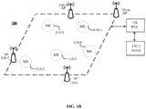
- FIG. 1B shows an exemplary Network Based Positioning (NBP) system 200 capable of providing Location Services to one or more mobile stations 110-1 - 110-n (collectively sometimes referred to as mobile stations 110) and facilitating the exchange of capability information, location assistance data, and/or location related information.
- NBP system 200 may use mobile station motion detection to obtain estimates of the variability of positioning related metrics for one or more APs 120.
- system 200 may include server 150-3, Wireless LAN Controller ("WLC") 134, a network of Access Points (APs) 120-1 - 120-m (collectively sometimes referred to as APs 120).
- WLC Wireless LAN Controller
- APs Access Points
- NBP system 200 may be deployed in an indoor environment.
- APs 120 may be managed using WLC 134.
- Each AP 120 may act as a transmitter and receiver of wireless network radio signals for the WLAN or WPAN.
- a network administrator or network operations center may use WLC 134 in combination with server 150-3 to automatically configure APs 120 across the network.
- WLC 134 may be used to discover, provision, and authenticate APs 120 in system 200, to set network policies and/or for network surveillance.
- various protocols based on IEEE 802.11x family of standards such as Control and Provisioning of Access Points (CAPWAP) and/or other protocols such as Lightweight Access Point Protocol (LWAPP) may be installed on server 150-3 and used along with WLC 130 to control and configure multiple APs 120 in system 200.
- CAPWAP Control and Provisioning of Access Points
- LWAPP Lightweight Access Point Protocol
- the Media Access Control (MAC) address of the sender and receiver, protocol version, and other information pertaining to MS 110-i may be present in and/or obtained from MS 110-i (1 ⁇ i ⁇ n) and/or in packets/frames transmitted between MS 110-i and APs 120.
- Frame types defined in the IEEE 802.11x family of protocols include data, control and management frames.
- management or control frames may be used by APs 120 to obtain information pertaining to a current configuration of MS 110-i.
- Each MS 110 can be uniquely identified through its Media Access Control (MAC) address.
- the location of MS 110-i (1 ⁇ i ⁇ n) connected to the network may be determined upon a request from the MS 110-i (MS initiated), or at the request of another network entity (network initiated), such as server 150-3, WLC 134, and/or AP 120-j (1 ⁇ j ⁇ m).
- MS 110-i may initiate a positioning process to determine its location by undertaking measurements of one or more metrics pertaining to some subset of APs 120-1 to 120-m.
- the metrics measured by MS 110- i may include, without limitation, for example, RTT/RSSI values for one or more APs 120- j .
- MS 110- i , server 150-3, and/or another network entity may also compute the position of MS 110- i through trilateration of the RTT measurements for multiple APs 120 and/or various other appropriate methods.
- APs 120- j may be used by various vendors.
- APs 120- j served by NBP system 200 may have a variety of Wi-Fi chipsets, which may exhibit different characteristics despite the fact that the served mobile stations 110- i and the APs 120- j may comply with the IEEE 802.11 or another relevant standard.
- these differences in chipset and other MS characteristics may affect the accuracy and/or reliability of the measured metrics and NBP mobile station location estimates that are based on those metrics.
- systems and methods consistent with embodiments disclosed herein increase the reliability and accuracy of location estimates for MS 110 provided by NBP system 200, in part, by increasing the number of RTT measurements taken when MS 110 is stationary, or when MS 110 is moving with a speed that does not exceed some threshold.
- systems and methods may further estimate the variability of positioning related metrics for one or more APs 120- j in exemplary NBP system 200.
- the variability of measured Round Trip Time (RTT) parameter values for an AP 120- j may be determined from measurements by MS 110- i .
- the estimated variability may be used, in part, to correct measured values of metrics associated with the one or more APs 120- j thereby increasing the reliability and accuracy of location estimates for MS 110.
- the utilization of motion detection to estimate the variability of positioning related metrics for one or more APs 120- j may be performed in real time and using standard IEEE 802.11x frame exchanges. Accordingly, in one application, exemplary NBP system 200 may be able to achieve and maintain levels of performance, accuracy and reliability in location estimates by using motion detection to estimate the variability of positioning related metrics for one or more APs 120- j . System and methods disclosed herein permit a reduction of the impact of individual AP 120- j device characteristics on the performance, accuracy and reliability of location estimates provided by NBP system 200.
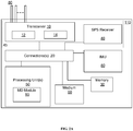
- FIG. 2A shows a schematic block diagram illustrating certain exemplary features of MS 110.
- MS 110 may, for example, include various functional units such as one or more processing units 50, Inertial Measurement Unit (IMU) 80, memory 30, transceiver 10 (e.g., wireless network interface), transmitter 12, receiver 14, and (as applicable) an SPS receiver 40, and non-transitory computer-readable medium 60, which may comprise removable media in a removable media drive (not shown).
- the functional units in mobile device 110 may be operatively coupled through one or more connections 20 (e.g., buses, lines, fibers, links, etc.).
- connections 20 e.g., buses, lines, fibers, links, etc.
- all or part of MS 110 may take the form of a chipset, and/or the like.
- transceiver 10 (comprising transmitter 12 and receiver 14) and (as applicable) an SPS receiver 40 may be embodied within or form part of communications interface 45.
- communications interface 45, transceiver 10 and/or SPS receiver 40 may comprise chipsets or other functional units that may be capable of undertaking measurements of signal parameters such as, but not limited to RTT and/or RSSI.
- the functional units may be capable of RTT measurements in the order of nanoseconds.
- Satellite Positioning System (SPS) receiver 40 in mobile station 110, may be enabled to receive signals associated with one or more SPS resources.
- the speed of MS 110 may be determined based on information received by SPS receiver 40 from one or more SPS systems.
- transceiver 10 may, for example, include a transmitter 12 enabled to transmit one or more signals over one or more types of wireless communication networks and a receiver 14 to receive one or more signals transmitted over the one or more types of wireless communication networks.
- transmitter 12 and receiver 14 may be able to able to communicate with wireless networks including WLANs, WPANs, WWANs/cellular networks, femtocells, and various other types wireless communication networks.
- the measurement point of reference for received (transmitted) RF signal measurements may be an input (output) terminal of the receiver 14 (transmitter 12) and an output (input) terminal of antennas 80.
- the antenna connector may be viewed as a virtual point representing the aggregate output (input) of multiple antennas 80.
- Processing unit(s) 50 may be implemented using a combination of hardware, firmware, and software. Processing unit(s) 50 may be capable of receiving instructions/data from receiver 14 and/or retrieving instructions/data from memory 30 and may respond to the instructions and/or send data/results using transmitter 12. For example, the instructions received and/or retrieved may pertain to a portion of a process to undertake and/or report measured signal metrics associated with one or more APs 120. Processing unit 50 may also be capable of processing various other received information either directly or in conjunction with one or more other functional blocks shown in Fig. 1 .
- processing units 50 may also receive input from IMU 80.
- IMU 80 may comprise 3 axis accelerometer(s), 3-axis gyroscope(s), and/or magnetometer(s).
- IMU 80 may provide speed, orientation, and/or other position related information to processing units 50.
- the output of IMU 80 may be processed by Motion Detection (MD) module 90.
- MD module 90 may provide an indication to processing unit(s) 50 when MS 110 is stationary.
- MD module 90 may provide a "low speed" indication to processing unit(s) 50 or an application running on processing unit(s) 50, whenever MS 110 has a speed that does not exceed a threshold.
- the speed threshold or threshold may be configurable and/or predetermined based on system parameters for a wireless network such as NBP 200. Accordingly, if the threshold is set to zero, then, MD module 90 may provide an indication when MS 110 is stationary.
- MD module 90 may provide the low speed indication at regular intervals. In another embodiment, the low speed indicator may be updated upon a change in speed status of MS 110 relative to the threshold. In some embodiments, the estimated speed of MS 110, which may be based on the output of IMU 80 and/or other sensors on MS 110, may be provided along with a low speed indication. In another embodiment, MD module 90 may categorize the speed of MS 110 based on the output of IMU 80 into a one of several classes and provide an indication of speed class based on the current estimated speed of MS 110. In some embodiments, the frequency of metric measurement may be varied based on the current speed-class classification of MS 110.
- processing units 50 and/or an application running on processing units 50 may be configured to send a message to one or more of servers 150, whenever MD module 90 indicates an MS speed that is less than or equal to the threshold.
- the message sent to servers 150 may include the value of low speed indicator (e.g. "0" or "1") and/or the estimated speed of MS 110.
- a message sent to server(s) 150 may include the estimated speed of MS 110 (based on the output of IMU 80), and servers 150 may determine whether reported speed exceeds some threshold speed.
- the availability of an estimated speed and/or low speed indicator may be indicated to servers 150 as part of capability information for MS 110.
- the estimated speed and/or low speed indicator may be sent to servers 150 in connection with a message requesting location assistance information, and/or in response to a request from one or more of servers 150.
- the low speed indicator may be provided as a single bit in a message to a server, with "1" indicating that the speed of MS 110 is not greater than the threshold; and a "0" indicating that the speed of MS 110 is above the threshold.
- Memory 30 may be implemented within processing unit(s) 50 and/or external to processing unit(s) 50.
- memory refers to any type of long term, short term, volatile, nonvolatile, or other memory and is not to be limited to any particular type of memory or number of memories, or type of physical media upon which memory is stored.
- memory 30 may hold code to facilitate the operation of mobile device 110, and other tasks performed by processing unit(s) 50.
- memory 30 may hold data, saved mobile device states, current speed information, and code to report the speed indicator, current speed and/or a speed state change to servers 150.
- Memory 30 may also include information about one or more modes of operation, a current configuration of MS 110, configuration history, program results, etc.
- memory 30 may represent any data storage mechanism.
- Memory 30 may include, for example, a primary memory and/or a secondary memory.
- Primary memory may include, for example, a random access memory, read only memory, etc. While illustrated in FIG. 2 as being separate from processing unit(s) 50, it should be understood that all or part of a primary memory may be provided within or otherwise co-located and/or coupled to processing unit(s) 50.
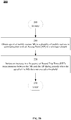
- FIG. 2B shows a flowchart illustrating steps in an exemplary method 200 for utilizing motion detection to vary the frequency of metric measurements.
- method 200 may be performed by MS 110 or a server such as server 150-3.
- method 200 may start in step 205.
- step 210 the speed of MS 110 in a plurality of mobile stations in communication with an AP 120 in a wireless network may be obtained.
- an increase in the frequency of Round Trip Time (RTT) measurements between the MS 110 and the AP 120 during periods when the speed of the MS does not exceed a threshold may be initiated.
- the increased frequency of RTT measurements between the MS and the AP may be relative to one or more periods when the speed of the MS exceeds the threshold.
- the threshold may be zero.
- the speed of the MS may be obtained based on measurements by IMU 80on the MS and/or information provided by SPS'.
- increased frequency of RTT measurements between MS 110 and AP 120 is initiated if a Received Signal Strength Indicator (RSSI) value associated with AP 120 and measured at the MS 110 is not less than a desired RSSI level.
- RSSI Received Signal Strength Indicator
- FIG. 3A shows a flowchart illustrating steps in an exemplary method 300 for estimating RTT variability associated with AP 120- j .
- portions of method 300 may be implemented using program code on MS 110, servers 150 and/or another network entity in system 100.
- a process running on servers 150 and/or another network entity may direct one or more MS' 110- i to perform one or more steps in method 300.
- server 150 may perform method 300 by obtaining and processing a set of RTT measurements for one or more APs 120.
- one or more steps in method 300 may be combined and/or omitted in a manner consistent with disclosed embodiments.
- method 300 may start in step 305 when one or more mobile stations connect to an AP (such as exemplary AP 120- j , 1 ⁇ j ⁇ m) in the network. In some embodiments, method 300 may be run for a new AP 120- j when AP 120- j is added to the network and mobile stations connect to AP 120- j . In some embodiments, method 300 may be invoked upon request by a server for any AP 120- j that is currently serving one or more mobile stations 110. In some embodiments, method 300 may be performed concurrently for a plurality of APs in the network. In some embodiments, method 300 may be initiated when MS' 110 connect and/or reconnect with AP 120- j .
- AP such as exemplary AP 120- j , 1 ⁇ j ⁇ m
- mobile station MS 110- i , 1 ⁇ i ⁇ n may be selected from a subset comprising n mobile stations connected to exemplary AP 120- j .
- the RSSI is compared to a desired RSSI level denoted as RSSI level .
- the desired RSSI level RSSI level may be set to a value that ensures accuracy of subsequent measurements. If the measured RSSI level is below the desired RSSI level RSSI level ("No" in step 320), then, the method may proceed to step 350, where the availability of other mobile stations in the subset may be determined. In some embodiments, if the measured RSSI level associated with an AP 120- j is below RSSI level then, RTT measurements using MS 110- i can be deferred to a later time.
- the RSSI level of MS 110- i may be monitored and periodically checked against RSSI level to determine if method 300 can be restarted.
- RSSI level may be selected to ensure reliable RTT estimation for MS 110- i . If the measured RSSI level, as determined by and/or reported to serving AP 120- j to which exemplary MS 110- i is connected, is not less than RSSI level ("Yes" in step 320), then the method proceeds to step 330. In some embodiments, step 320 may be omitted and the method may proceed directly to step 330.
- step 330 the speed of MS 110- i may be obtained and compared to a threshold v threshold . If the speed of MS 110- i is greater than v threshold ("No" in step 330), then, the method may proceed to step 350, where the availability of other mobile stations in the subset may be determined. In some embodiments, if the speed of MS 110- i exceeds v threshold , then an increase in the frequency of RTT measurements using MS 110- i can be deferred to a later time. For example, the speed of MS 110- i may be monitored and periodically checked against the threshold speed level to determine if the frequency of measurements can be increased at a later point in time.
- MS 110- i may be requested to report measured speed to serving AP 120- j at periodic intervals and the frequency of metric measurements increased when the measured speed of MS 110- i is not greater than v threshold .
- the speed threshold level may be selected to ensure accurate and/or reliable RTT estimation for exemplary MS 110- i .
- v threshold may set to zero.
- IMU 80 and/or other sensors on MS 110- i may be used to determine the speed of MS 110- i .
- the speed of MS 110- i may be determined and/or reported by MS module 90.
- an increase in the frequency of RTT measurements for MS 110- i may be initiated and corresponding RTT measurements obtained.
- the number of measurements collected in step 340 may be increased relative to other measurement periods.
- the number of measurements collected may be higher than the number typically collected and/or used during the actual positioning of an exemplary MS 110- i .
- the RTT measurements collected may be stored on one of servers 150 and associated with a tuple comprising an identifier (such as a timestamp) for the set of RTT measurements, an identifier (such as a MAC address) for AP 120- j , an identifier for MS 110- i (such as a MAC address and/or IMEI/IMSI/TMSI number), and/or an RTT estimated distance associated with the RTT measurements.
- a set of RTT measurements undertaken for an MS 110- i in step 340 by an AP 120- j may be associated using a common timestamp for the set or another identifier.
- the increased frequency of RTT measurements may be collected by AP 120- j from MS 110- i so long as the speed of MS 110- i does not exceed v threshold .
- some predetermined higher number of RTT measurements for MS 110- i may be taken in step 340 over some specified period so long as the speed of MS 110- i does not exceed v threshold .
- MS 110- i and/or AP 120- j may lower the frequency of RTT measurements, as the speed of MS 110- i increases.
- RTT measurements may be stopped or the frequency of RTT measurements may be further lowered when the speed of MS 110- i exceeds v threshold .
- step 350 the method may determine if there are additional mobile stations in the subset, for which RTT measurements have not yet been taken. If there are mobile stations in the subset for which no measurements have been undertaken ("Yes" in step 350), then the method proceeds to step 360, where the next/new mobile station is selected. The method then returns to step 320 to begin another iteration.
- step 350 If there are no further mobile stations in the subset for AP to undertake measurements ("No" in step 350), then the method proceeds to step 370, where statistical techniques may be used to compute a measure of variability of the RTT measurements between MS 110- i and AP 120- j obtained in step 340. For example, a standard deviation, average absolute deviation, median absolute deviation, and/or variance of the RTT measurements obtained in step 340 may be obtained and associated with AP 120- j .
- RTT measurements obtained in step 340 may be categorized based on the RTT estimated distance between MS 110- i and AP 120- j .
- the RTT measurements for each distance category and may then be used in conjunction with prior RTT measurements for that distance category to obtain an overall standard deviation (across mobile stations) for all measurements for AP 120- j in a distance category.
- the RTT measurements for AP 120- j may be normalized based on the RTT estimated distance(s) and an overall standard deviation or another statistical measure of variability associated with AP 120- j may be obtained using the normalized RTT values. Because mobile stations may be located at different distances from the AP, normalization of the RTT values may be performed to obtain a common measure of variability across the RTT values measured by the diverse set of mobile stations. As used herein, normalization refers to the adjustment of RTT values measured at different distances to a notionally common distance. Accordingly, measured RTT values may be used to estimate a distance between the MS and AP and the RTT values may be scaled up or down to obtain normalized RTT values based on the normalization distance.
- a measure of variability such as a variance, standard deviation, average absolute deviation, and/or median absolute deviation may be computed for AP 120- j .
- the RTT measurements obtained may be subjected to aging, and older RTT measurements may be discarded in favor of newer measurements and the RTT variability measures associated with AP 120- j may be updated.
- method 300 may be repeated for other APs 120 deployed on the network. The method may stop in step 380.
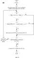
- FIG. 3B shows a flowchart illustrating steps in an exemplary method 380 for estimating RTT variability associated with an access point.
- one or more mobile stations connected to an access point may each perform method 380.
- method 380 may be performed by mobile stations and/or a server.
- one or more mobile stations connected to an access point may measure RTT values and may report the measured RTT values and related information to a server, such as a crowdsourcing server, which may aggregate the measurements and apply statistical techniques to the measured values.
- method 300 may be performed concurrently for several APs by different connected mobile stations concurrently.
- mobile stations connected to an AP may concurrently perform method 300 and the process may occur concurrently with the performance of method 300 by other mobile stations connected to other APs in the network.
- one or more steps in method 300 may be combined and/or omitted in a manner consistent with disclosed embodiments. Steps labeled with the same identifiers perform similar functions in methods 300 and 380.
- MS 110- i may be requested to report measured RSSI levels for serving AP 120- j at periodic intervals and the method may be restarted when the measured RSSI level is not less than RSSI threshold .
- method 380 may start when a mobile station MS 110- i initially connects to a wireless network in step 305.
- mobile station MS 110- i , 1 ⁇ i ⁇ n may select the first or next AP 120- j 1 ⁇ j ⁇ m from a subset comprising m access points connected to and/or visible to MS 110- i .
- MS 110- i may select one of the connected APs or may connect to one of the visible APs.
- the measured RSSI of serving AP 120- j may be compared to a desired RSSI level denoted as RSSI level . If the measured RSSI level is below RSSI level ("No" in step 320), then, in step 385, RTT measurement by MS 110- i may potentially be deferred to later point in time. For example, an application on MS 110- i may monitor and periodically check the measured RSSI of serving AP 120- j against RSSI level to determine if method 380 can be restarted. In some embodiments, if the measured RSSI level of the AP 120- j is not below the desired RSSI level RSSI level ("Yes" in step 320), then, the method may proceed to step 330.
- step 330 the speed of MS 110- i is compared to a threshold v threshold . If the speed of MS 110- i is greater than v threshold ("No" in step 330), then, then, in step 385, increasing a frequency of RTT measurement(s) by MS 110- i may potentially be deferred to later point.
- the speed of MS 110- i may be monitored and periodically checked against the threshold speed level to determine if the frequency of RTT measurements can be increased.
- MS 110- i may be requested to report measured speed to serving AP 120- j at periodic intervals and the frequency of RTT measurements increased when the measured speed of MS 110- i is not greater than v threshold .
- IMU 80 and/or other sensors on MS 110- i may be used to determine the speed of MS 110- i .
- the speed of MS 110- i may be determined and/or reported by MD module 90.
- step 330 if the speed of MS 110- i does not exceed v threshold ("Yes" in step 330), then, in step 384, the frequency of RTT measurements for AP 120- j may be increased. In some embodiments, the frequency of measurements collected may be increased in step 384, relative to the frequency of RTT measurements obtained during other periods. In some embodiments, the number of RTT measurements obtained in step 384 may be higher than the number typically collected and/or used during the actual positioning of an exemplary MS 110- i .
- the RTT measurements collected may be stored on MS 110- i and associated with a tuple comprising an identifier for the set of RTT measurements (such as a timestamp), an identifier for AP 120- j (such as a MAC address), an identifier for MS 110- i (such as a MAC address and/or IMEI/IMSI/TMSI number), and/or an RTT estimated distance associated with the RTT measurements.
- a tuple comprising an identifier for the set of RTT measurements (such as a timestamp), an identifier for AP 120- j (such as a MAC address), an identifier for MS 110- i (such as a MAC address and/or IMEI/IMSI/TMSI number), and/or an RTT estimated distance associated with the RTT measurements.
- a set of RTT measurements undertaken for an MS 110- i in step 384 by an AP 120- j during a measurement period may be associated using a common index (which may be a timestamp) or another identifier.
- an increased frequency of RTT measurements between MS 110- i and AP 120- j may be maintained so long as the speed of MS 110- i does not exceed v threshold .
- some predetermined number of RTT measurements for may be taken over some period so long as the speed of MS 110- i does not exceed v threshold .
- MS 110- i may lower the measurement frequency and/or stop taking measurements, if the speed of MS 110- i exceeds v threshold .
- step 370 statistical techniques may be used to compute a measure of variability of the RTT measurements between MS 110- i and AP 120- j obtained in step 384. For example, a standard deviation, average absolute deviation, median absolute deviation, and/or variance of normalized RTT values (as obtained using equation 1 above) and based on the RTT measurements obtained in step 340, may be computed and associated with AP 120- j .
- the measurements collected by distinct mobile stations may be sent to a server, such as a crowdsourcing server, which may aggregate and perform statistical analysis of the measured values to determine a measure of variability associated with measurements related to AP 120- j .
- step 387 if there are additional APs in the subset, then, the process may return to step 382 to select the next AP 120- j from the set of APs and begin another iteration.
- FIG. 4 shows a flowchart of an exemplary method for location determination of MS 110- i in a manner consistent with disclosed embodiments.
- method 400 may start in step 410, when MS 110- i , AP 120- j , server 150, an LCS client and/or another network entity initiates a location determination process.
- the MAC address or another identifier associated with APs 120- j that are available for location determination may be used to obtain the respective stored RTT variabilities information.
- a location determination scheme or APs may be selected based on the respective stored RTT variabilities information. For example, if the RTT variability information indicates that RTT variability for a specific AP 120- j is high, then, then that AP 120- j may not be selected for use in location determination, if alternate APs are available. In some embodiments, APs 120-j with the lowest RTT variability that are available / visible to MS 110- i may be selected for location determination. In another embodiment, an alternate (non-RTT) scheme may be used in the event that RTT variability is high.
- the number of RTT measurements taken for an AP 120- j may be based, in part, on the RTT variability information associated with that AP 120- j . For example, a lower number of RTT measurements may be taken if RTT variability for an AP 120- j is low, while a greater number of RTT measurements may be taken if RTT variability for an AP 120- j is high.
- step 430 location determination may be performed based on the scheme selected in step 430.
- step 435 the method may determine if RTT measurements were used to determine the location of MS 110- i . If an RTT based location determination scheme was used in step 430 ("Y" in step 435) then, in step 440, an error range or confidence measure associated with the RTT-based location estimate may be provided. The error range and/or confidence measure may be based, in part, on the respective RTT variability measures associated with APs 120- j that were used for location determination in step 430. If an alternate (non-RTT based) scheme was used for location determination in step 430 ("No" in step 435), then, the method may terminate in step 445.
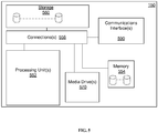
- FIG. 5 shows a schematic block diagram illustrating exemplary server 150 enabled to estimate RTT variability associated with an access point in a manner consistent with disclosed embodiments.
- server 150 may include, for example, one or more processing units 552, memory 554, storage 560, and (as applicable) communications interfaces 590 (e.g., wireline and/or wireless network interfaces).
- the functional units listed above as well as other functional units may be operatively coupled with one or more connections 556 (e.g., buses, lines, fibers, links, etc.).
- connections 556 e.g., buses, lines, fibers, links, etc.
- some portion of server 150 may take the form of a chipset, and/or the like.
- Communications interfaces 590 may include a variety of wired and/or wireless connections that support wired transmission and/or reception and, if desired, may additionally or alternatively support transmission and reception of one or more signals over one or more types of wireless communication networks. Communications interfaces 590 may also include interfaces for communication with various other computers and peripherals. For example, in one embodiment, communications interfaces 590 may comprise network interface cards, input-output cards, chips and/or ASICs that implement one or more of the communication functions performed by server 150. In some embodiments, communications interface(s) 590 may also interface with WLC 134 or another network entity to obtain a variety of network configuration related information, such as connected devices, device configuration information, MAC addresses of connected devices, etc.
- server 150 may also use communications interfaces 590 to direct WLC 134 to configure APs 120 to perform portions of a method for estimating RTT variability associated with an access point, or to enforce network policies. Further, server 150 may receive MS related information including values of measured parameters from WLC 134 through communications interfaces 590. In general, communications interfaces 590 may be used to send and receive data, control, management, and configuration information related to NBP system 200 to various network entities.
- Processing unit(s) 552 may be implemented using a combination of hardware, firmware, and software.
- processing unit 552 may also optionally include an AP characterization module, location determination module and/or a location assistance module (not shown) to facilitate estimation of RTT variability associated with one or more access points 120, determine the location of MS 110, and/or to provide location assistance information, respectively.
- server 140 may provide RTT variability information associated with one or more access points 120 as location assistance information.
- server 150 may use processing units 552 to implement methods 300 and 400.
- the functionality in exemplary methods 300 and 400 may be combined in to a single module.
- Processing unit 552 may also be capable of processing various other types of network related, location related and/or AP characterization related information either directly or in conjunction with one or more other functional blocks shown in Fig. 5 .
- the processing unit 552 may be implemented within one or more application specific integrated circuits (ASICs), digital signal processors (DSPs), digital signal processing devices (DSPDs), programmable logic devices (PLDs), field programmable gate arrays (FPGAs), processors, controllers, micro-controllers, microprocessors, electronic devices, other electronic units designed to perform the functions described herein, or a combination thereof.
- ASICs application specific integrated circuits
- DSPs digital signal processors
- DSPDs digital signal processing devices
- PLDs programmable logic devices
- FPGAs field programmable gate arrays
- processors controllers, micro-controllers, microprocessors, electronic devices, other electronic units designed to perform the functions described herein, or a combination thereof.
- the methodologies may be implemented with modules (e.g., procedures, functions, and so on) that perform the functions described herein.
- Any machine-readable medium tangibly embodying instructions may be used in implementing the methodologies described herein.
- software may be stored in media drive 570, which may support the use of non-transitory computer-readable media, including removable media.
- Program code may be resident on non-transitory computer readable media or memory 554 and may be read and executed by processor unit(s) 552.
- Memory may be implemented within processing units 552 or external to processing units 552.
- the term "memory" refers to any type of long term, short term, volatile, nonvolatile, or other memory and is not to be limited to any particular type of memory or number of memories, or type of media upon which memory is stored.
- the functions may be stored as one or more instructions or code on a non-transitory computer-readable medium and/or memory 554.
- Examples include computer-readable media encoded with a data structure and computer-readable media encoded with a computer program.
- non transitory computer-readable medium including program code stored thereon may include program code to support motion detection, AP characterization, location determination and/or location assistance of MS 110 in a manner consistent with disclosed embodiments.
- Non-transitory computer-readable media includes a variety of physical computer storage media.
- a storage medium may be any available medium that can be accessed by a computer.
- such non-transitory computer-readable media can comprise RAM, ROM, EEPROM, CD-ROM or other optical disc storage, magnetic disk storage or other magnetic storage devices, or any other medium that can be used to store desired program code in the form of instructions or data structures and that can be accessed by a computer;
- disk and disc includes compact disc (CD), laser disc, optical disc, digital versatile disc (DVD), floppy disk and blu-ray disc where disks usually reproduce data magnetically, while discs reproduce data optically with lasers.
- Other embodiments of non-transitory computer readable media include flash drives, USB drives, solid state drives, memory cards, etc. Combinations of the above should also be included within the scope of computer-readable media.
- instructions and/or data may be provided as signals on transmission media to communications interfaces 590, which may store the instructions/data in memory 554, storage 560 and/or relay the instructions/data to processing units 552 for execution.
- communications interfaces 590 may receive wireless or network signals indicative of instructions and data.
- the instructions and data may cause one or more processing units 552 to be configured to implement one or more functions outlined in the claims. That is, the communication apparatus includes transmission media with signals indicative of information to perform disclosed functions.
- Memory 554 may represent any data storage mechanism.
- Memory 554 may include, for example, a primary memory and/or a secondary memory.
- Primary memory may include, for example, a random access memory, read only memory, nonvolatile RAM, etc. While illustrated in this example as being separate from processing units 552, it should be understood that all or part of a primary memory may be provided within or otherwise co-located/coupled with processing units 552.
- Secondary memory may include, for example, the same or similar type of memory as primary memory and/or storage 560 such as one or more data storage devices or systems 560 including, for example, hard disk drives, optical disc drives, tape drives, a solid state memory drive, etc.
- storage 560 and/or memory 554 may comprise one or more databases that may hold information pertaining to various entities in NBP system 200.
- storage 560 and/or memory 554 may include databases such as AP characterization databases with records for APs 120 in NBP system 200.
- the AP characterization databases may identify APs 120 by their MAC addresses and hold an AP characterization record for each MAC address.
- An AP characterization record for an AP 120- j may comprise the MAC address of AP 120- j and RTT variability information associated with AP 120- j , classification group of AP 120- j , where the classification is made based on the RTT variability.
- the APs may be classified based on the RTT measurements as consistent, moderately variable, or unreliable.
- the characterization record may comprise the RTT variability measure, the individual RTT measurement records, and other information.
- information in the databases may be read, used and/or updated by processing units 552 during various computations.
- secondary memory may be operatively receptive of, or otherwise configurable to couple to a non-transitory computer-readable medium in media drive 570.
- the methods and/or apparatuses presented herein may take the form in whole or part of a media drive 570 that may include non-transitory computer readable medium with computer implementable instructions stored thereon, which if executed by at least one processing unit 352 may be operatively enabled to perform all or portions of the example operations as described herein.
Landscapes
- Engineering & Computer Science (AREA)
- Computer Networks & Wireless Communication (AREA)
- Signal Processing (AREA)
- Physics & Mathematics (AREA)
- General Physics & Mathematics (AREA)
- Radar, Positioning & Navigation (AREA)
- Remote Sensing (AREA)
- Probability & Statistics with Applications (AREA)
- Mobile Radio Communication Systems (AREA)
- Position Fixing By Use Of Radio Waves (AREA)
Applications Claiming Priority (2)
| Application Number | Priority Date | Filing Date | Title |
|---|---|---|---|
| US13/928,107 US9357354B2 (en) | 2013-06-26 | 2013-06-26 | Utilizing motion detection in estimating variability of positioning related metrics |
| PCT/US2014/043933 WO2014210049A2 (en) | 2013-06-26 | 2014-06-24 | Utilizing motion detection in estimating variability of positioning related metrics |
Publications (2)
| Publication Number | Publication Date |
|---|---|
| EP3014295A2 EP3014295A2 (en) | 2016-05-04 |
| EP3014295B1 true EP3014295B1 (en) | 2018-11-07 |
Family
ID=51211343
Family Applications (1)
| Application Number | Title | Priority Date | Filing Date |
|---|---|---|---|
| EP14741474.2A Not-in-force EP3014295B1 (en) | 2013-06-26 | 2014-06-24 | Utilizing motion detection in estimating variability of positioning related metrics |
Country Status (5)
| Country | Link |
|---|---|
| US (2) | US9357354B2 (enExample) |
| EP (1) | EP3014295B1 (enExample) |
| JP (1) | JP2016530498A (enExample) |
| CN (2) | CN107450050B (enExample) |
| WO (1) | WO2014210049A2 (enExample) |
Families Citing this family (20)
| Publication number | Priority date | Publication date | Assignee | Title |
|---|---|---|---|---|
| US9357354B2 (en) | 2013-06-26 | 2016-05-31 | Qualcomm Incorporated | Utilizing motion detection in estimating variability of positioning related metrics |
| WO2015021638A1 (zh) * | 2013-08-15 | 2015-02-19 | 华为技术有限公司 | 一种判断节点移动的方法和设备 |
| KR101548210B1 (ko) * | 2014-01-06 | 2015-08-31 | 고려대학교 산학협력단 | 왕복 시간 변화를 이용하여 익명 네트워크를 통한 우회 접속을 탐지하는 방법 |
| EP3215864B1 (en) * | 2014-11-07 | 2020-07-29 | Sony Corporation | Determining the geographic location of a portable electronic device with a synthetic antenna array |
| US9892363B2 (en) * | 2015-05-07 | 2018-02-13 | Truemotion, Inc. | Methods and systems for sensor-based driving data collection |
| US9781560B2 (en) | 2015-07-02 | 2017-10-03 | Qualcomm Incorporated | Ranging over multiple antennas |
| DE102015118152A1 (de) * | 2015-10-23 | 2017-04-27 | clownfisch information technology GmbH | Verfahren zum Bestimmen einer Position einer Mobileinheit |
| JP2017156257A (ja) * | 2016-03-03 | 2017-09-07 | Necプラットフォームズ株式会社 | 無線通信装置、位置情報通知システム、および位置情報通知方法、並びにコンピュータ・プログラム |
| US10165530B2 (en) * | 2016-03-22 | 2018-12-25 | Christoph RULAND | Verification of time information transmitted by time signals or time telegrams |
| GB2550108B (en) * | 2016-04-14 | 2019-11-06 | Paul Mccormack T/A Pactac | Radio locator system |
| US10859595B2 (en) * | 2017-04-04 | 2020-12-08 | Qualcomm Incorporated | Systems and methods for improving location accuracy for a mobile device using sensors |
| JP6645665B1 (ja) * | 2018-12-12 | 2020-02-14 | Necプラットフォームズ株式会社 | 通信システム、アクセスポイント、無線lan端末、通信制御方法及び通信制御プログラム |
| US10667235B1 (en) * | 2019-03-22 | 2020-05-26 | Eric Yellin | Server and plurality of access points for locating and identifying a mobile device |
| US11480432B2 (en) | 2019-06-27 | 2022-10-25 | Novatel Inc. | System and method for IMU motion detection utilizing standard deviation |
| US11323935B2 (en) * | 2020-06-11 | 2022-05-03 | Dell Products, L.P. | Crowdsourced network identification and switching |
| US11395252B2 (en) | 2020-07-23 | 2022-07-19 | Skyhook Wireless, Inc. | Crowd sourced RTT-based positioning |
| US20230403675A1 (en) * | 2020-10-30 | 2023-12-14 | Purple Mountain Laboratories | Positioning Method, Apparatus, Device and System, and Storage Medium |
| CN115623578A (zh) * | 2021-07-16 | 2023-01-17 | 中国移动通信有限公司研究院 | 一种时间测量方法、设备及存储介质 |
| CN117897973A (zh) * | 2023-11-03 | 2024-04-16 | 上海移远通信技术股份有限公司 | 无线通信方法、终端设备、基站以及定位服务器 |
| CN117890949B (zh) * | 2024-03-14 | 2024-05-24 | 山东科技大学 | 一种顾及mac地址的gnss和rssi融合定位方法 |
Citations (1)
| Publication number | Priority date | Publication date | Assignee | Title |
|---|---|---|---|---|
| US20120295642A1 (en) * | 2010-02-17 | 2012-11-22 | Ntt Docomo, Inc | Positioning time interval control device and positioning time interval control method |
Family Cites Families (25)
| Publication number | Priority date | Publication date | Assignee | Title |
|---|---|---|---|---|
| US6147644A (en) * | 1996-12-30 | 2000-11-14 | Southwest Research Institute | Autonomous geolocation and message communication system and method |
| FI106602B (fi) | 1998-03-31 | 2001-02-28 | Nokia Networks Oy | Aikaeron mittausmenetelmä ja radiojärjestelmä |
| US6681099B1 (en) | 2000-05-15 | 2004-01-20 | Nokia Networks Oy | Method to calculate true round trip propagation delay and user equipment location in WCDMA/UTRAN |
| FR2830397B1 (fr) * | 2001-09-28 | 2004-12-03 | Evolium Sas | Procede pour ameliorer les performances d'un protocole de transmission utilisant un temporisateur de retransmission |
| CN102223710B (zh) * | 2003-06-27 | 2015-10-14 | 高通股份有限公司 | 用于无线网络混合定位的方法和设备 |
| KR100694104B1 (ko) | 2005-02-23 | 2007-03-12 | 삼성전자주식회사 | 라운드 트립 시간을 측정하는 방법 및 이를 이용한 인접성검사 방법 |
| US8589532B2 (en) | 2005-06-24 | 2013-11-19 | Qualcomm Incorporated | Apparatus and method for determining WLAN access point position |
| CN101253738B (zh) * | 2005-07-07 | 2014-06-11 | 高通股份有限公司 | 用于无线广域网和无线局域网或无线个域网的交互工作的方法和装置 |
| US8270933B2 (en) * | 2005-09-26 | 2012-09-18 | Zoomsafer, Inc. | Safety features for portable electronic device |
| US7692579B2 (en) * | 2006-11-24 | 2010-04-06 | Qualcomm Incorporated | Methods and apparatus for actuated position determination in a wireless communication device |
| JP2008249396A (ja) * | 2007-03-29 | 2008-10-16 | Brother Ind Ltd | 移動局の静止判定を利用した位置検出システム |
| US8489111B2 (en) * | 2007-08-14 | 2013-07-16 | Mpanion, Inc. | Real-time location and presence using a push-location client and server |
| US8036679B1 (en) * | 2007-10-03 | 2011-10-11 | University of South Floirda | Optimizing performance of location-aware applications using state machines |
| US8385226B2 (en) | 2008-04-25 | 2013-02-26 | Telefonaktiebolaget Lm Ericsson (Publ) | Radio fingerprint method in a positioning node for providing geographic region data |
| US20100135178A1 (en) | 2008-11-21 | 2010-06-03 | Qualcomm Incorporated | Wireless position determination using adjusted round trip time measurements |
| US8768344B2 (en) | 2008-12-22 | 2014-07-01 | Qualcomm Incorporated | Post-deployment calibration for wireless position determination |
| ES2358406B1 (es) | 2009-07-07 | 2012-03-22 | Vodafone España, S.A.U. | Controlador de red radio y método para seleccionar una tecnolog�?a de transmisión para una conexión hsdpa. |
| US20110039573A1 (en) * | 2009-08-13 | 2011-02-17 | Qualcomm Incorporated | Accessing positional information for a mobile station using a data code label |
| US8781492B2 (en) | 2010-04-30 | 2014-07-15 | Qualcomm Incorporated | Device for round trip time measurements |
| US8412232B2 (en) * | 2010-08-20 | 2013-04-02 | Qualcomm Incorporated | Methods and apparatuses for use in estimating a location of a mobile device within a structure |
| US8548493B2 (en) * | 2011-04-14 | 2013-10-01 | Navteq B.V. | Location tracking |
| WO2012169252A1 (ja) * | 2011-06-10 | 2012-12-13 | 日本電気株式会社 | 測位装置、測位方法、およびコンピュータ読み取り可能な記録媒体 |
| US9503519B2 (en) | 2011-11-25 | 2016-11-22 | Telefonaktiebolaget L M Ericsson | Method and arrangement for the supervision of transactions in a peer-to-peer overlay network |
| US9161171B2 (en) * | 2012-09-29 | 2015-10-13 | Mark Shaffer Annett | System and method for providing timely therapeutic interventions based on both public and private location-based messaging |
| US9357354B2 (en) | 2013-06-26 | 2016-05-31 | Qualcomm Incorporated | Utilizing motion detection in estimating variability of positioning related metrics |
-
2013
- 2013-06-26 US US13/928,107 patent/US9357354B2/en active Active
-
2014
- 2014-06-24 CN CN201710608924.3A patent/CN107450050B/zh not_active Expired - Fee Related
- 2014-06-24 EP EP14741474.2A patent/EP3014295B1/en not_active Not-in-force
- 2014-06-24 JP JP2016523858A patent/JP2016530498A/ja active Pending
- 2014-06-24 WO PCT/US2014/043933 patent/WO2014210049A2/en not_active Ceased
- 2014-06-24 CN CN201480035445.1A patent/CN105324680B/zh not_active Expired - Fee Related
-
2016
- 2016-04-07 US US15/093,432 patent/US9686768B2/en not_active Expired - Fee Related
Patent Citations (1)
| Publication number | Priority date | Publication date | Assignee | Title |
|---|---|---|---|---|
| US20120295642A1 (en) * | 2010-02-17 | 2012-11-22 | Ntt Docomo, Inc | Positioning time interval control device and positioning time interval control method |
Also Published As
| Publication number | Publication date |
|---|---|
| US9357354B2 (en) | 2016-05-31 |
| CN105324680B (zh) | 2017-07-14 |
| WO2014210049A3 (en) | 2015-02-26 |
| EP3014295A2 (en) | 2016-05-04 |
| JP2016530498A (ja) | 2016-09-29 |
| US20150005016A1 (en) | 2015-01-01 |
| US20160219550A1 (en) | 2016-07-28 |
| US9686768B2 (en) | 2017-06-20 |
| CN105324680A (zh) | 2016-02-10 |
| CN107450050A (zh) | 2017-12-08 |
| WO2014210049A2 (en) | 2014-12-31 |
| CN107450050B (zh) | 2020-10-13 |
Similar Documents
| Publication | Publication Date | Title |
|---|---|---|
| EP3014295B1 (en) | Utilizing motion detection in estimating variability of positioning related metrics | |
| EP3913933B1 (en) | Systems and methods for limiting a message size for a positioning protocol | |
| EP2974397B1 (en) | Crowdsourcing based on base station almanac quality | |
| EP3066814B1 (en) | Controlling crowdsourcing measurements from a mobile device | |
| US12411200B2 (en) | User equipment location information reporting method, user equipment, and network device | |
| CN104186015B (zh) | 最小化路测的位置选项控制及确定最佳定位程序的方法 | |
| CN112970297B (zh) | 用于具有双无线连接的移动设备的高效定位的系统和方法 | |
| US10542518B2 (en) | Mobile access point detection | |
| US11240706B2 (en) | Methods and systems for segmentation of positioning protocol messages | |
| US20140274111A1 (en) | Inter-device transfer of accurate location information | |
| WO2014137545A1 (en) | Dynamic characterization of mobile devices in network-based wireless positioning systems | |
| US20140162685A1 (en) | Discovery and support of proximity | |
| JP7734184B2 (ja) | 高速アップリンクシグナリングを使用する低レイテンシ測位のためのシステムおよび方法 | |
| US20220286999A1 (en) | User Equipment Location Information Reporting Method, User Equipment, and Network Device |
Legal Events
| Date | Code | Title | Description |
|---|---|---|---|
| PUAI | Public reference made under article 153(3) epc to a published international application that has entered the european phase |
Free format text: ORIGINAL CODE: 0009012 |
|
| 17P | Request for examination filed |
Effective date: 20151117 |
|
| AK | Designated contracting states |
Kind code of ref document: A2 Designated state(s): AL AT BE BG CH CY CZ DE DK EE ES FI FR GB GR HR HU IE IS IT LI LT LU LV MC MK MT NL NO PL PT RO RS SE SI SK SM TR |
|
| AX | Request for extension of the european patent |
Extension state: BA ME |
|
| DAX | Request for extension of the european patent (deleted) | ||
| STAA | Information on the status of an ep patent application or granted ep patent |
Free format text: STATUS: EXAMINATION IS IN PROGRESS |
|
| 17Q | First examination report despatched |
Effective date: 20170317 |
|
| GRAP | Despatch of communication of intention to grant a patent |
Free format text: ORIGINAL CODE: EPIDOSNIGR1 |
|
| STAA | Information on the status of an ep patent application or granted ep patent |
Free format text: STATUS: GRANT OF PATENT IS INTENDED |
|
| RIC1 | Information provided on ipc code assigned before grant |
Ipc: G01S 5/14 20060101ALI20180406BHEP Ipc: H04W 4/02 20090101ALI20180406BHEP Ipc: G01S 5/02 20100101AFI20180406BHEP |
|
| INTG | Intention to grant announced |
Effective date: 20180430 |
|
| GRAS | Grant fee paid |
Free format text: ORIGINAL CODE: EPIDOSNIGR3 |
|
| GRAJ | Information related to disapproval of communication of intention to grant by the applicant or resumption of examination proceedings by the epo deleted |
Free format text: ORIGINAL CODE: EPIDOSDIGR1 |
|
| GRAL | Information related to payment of fee for publishing/printing deleted |
Free format text: ORIGINAL CODE: EPIDOSDIGR3 |
|
| STAA | Information on the status of an ep patent application or granted ep patent |
Free format text: STATUS: EXAMINATION IS IN PROGRESS |
|
| INTC | Intention to grant announced (deleted) | ||
| GRAR | Information related to intention to grant a patent recorded |
Free format text: ORIGINAL CODE: EPIDOSNIGR71 |
|
| STAA | Information on the status of an ep patent application or granted ep patent |
Free format text: STATUS: GRANT OF PATENT IS INTENDED |
|
| GRAA | (expected) grant |
Free format text: ORIGINAL CODE: 0009210 |
|
| STAA | Information on the status of an ep patent application or granted ep patent |
Free format text: STATUS: THE PATENT HAS BEEN GRANTED |
|
| AK | Designated contracting states |
Kind code of ref document: B1 Designated state(s): AL AT BE BG CH CY CZ DE DK EE ES FI FR GB GR HR HU IE IS IT LI LT LU LV MC MK MT NL NO PL PT RO RS SE SI SK SM TR |
|
| INTG | Intention to grant announced |
Effective date: 20180928 |
|
| REG | Reference to a national code |
Ref country code: GB Ref legal event code: FG4D |
|
| REG | Reference to a national code |
Ref country code: CH Ref legal event code: EP Ref country code: AT Ref legal event code: REF Ref document number: 1062737 Country of ref document: AT Kind code of ref document: T Effective date: 20181115 |
|
| REG | Reference to a national code |
Ref country code: DE Ref legal event code: R096 Ref document number: 602014035570 Country of ref document: DE |
|
| REG | Reference to a national code |
Ref country code: IE Ref legal event code: FG4D |
|
| REG | Reference to a national code |
Ref country code: NL Ref legal event code: MP Effective date: 20181107 |
|
| REG | Reference to a national code |
Ref country code: LT Ref legal event code: MG4D |
|
| REG | Reference to a national code |
Ref country code: AT Ref legal event code: MK05 Ref document number: 1062737 Country of ref document: AT Kind code of ref document: T Effective date: 20181107 |
|
| PG25 | Lapsed in a contracting state [announced via postgrant information from national office to epo] |
Ref country code: NO Free format text: LAPSE BECAUSE OF FAILURE TO SUBMIT A TRANSLATION OF THE DESCRIPTION OR TO PAY THE FEE WITHIN THE PRESCRIBED TIME-LIMIT Effective date: 20190207 Ref country code: BG Free format text: LAPSE BECAUSE OF FAILURE TO SUBMIT A TRANSLATION OF THE DESCRIPTION OR TO PAY THE FEE WITHIN THE PRESCRIBED TIME-LIMIT Effective date: 20190207 Ref country code: HR Free format text: LAPSE BECAUSE OF FAILURE TO SUBMIT A TRANSLATION OF THE DESCRIPTION OR TO PAY THE FEE WITHIN THE PRESCRIBED TIME-LIMIT Effective date: 20181107 Ref country code: IS Free format text: LAPSE BECAUSE OF FAILURE TO SUBMIT A TRANSLATION OF THE DESCRIPTION OR TO PAY THE FEE WITHIN THE PRESCRIBED TIME-LIMIT Effective date: 20190307 Ref country code: AT Free format text: LAPSE BECAUSE OF FAILURE TO SUBMIT A TRANSLATION OF THE DESCRIPTION OR TO PAY THE FEE WITHIN THE PRESCRIBED TIME-LIMIT Effective date: 20181107 Ref country code: LV Free format text: LAPSE BECAUSE OF FAILURE TO SUBMIT A TRANSLATION OF THE DESCRIPTION OR TO PAY THE FEE WITHIN THE PRESCRIBED TIME-LIMIT Effective date: 20181107 Ref country code: FI Free format text: LAPSE BECAUSE OF FAILURE TO SUBMIT A TRANSLATION OF THE DESCRIPTION OR TO PAY THE FEE WITHIN THE PRESCRIBED TIME-LIMIT Effective date: 20181107 Ref country code: ES Free format text: LAPSE BECAUSE OF FAILURE TO SUBMIT A TRANSLATION OF THE DESCRIPTION OR TO PAY THE FEE WITHIN THE PRESCRIBED TIME-LIMIT Effective date: 20181107 Ref country code: LT Free format text: LAPSE BECAUSE OF FAILURE TO SUBMIT A TRANSLATION OF THE DESCRIPTION OR TO PAY THE FEE WITHIN THE PRESCRIBED TIME-LIMIT Effective date: 20181107 |
|
| PG25 | Lapsed in a contracting state [announced via postgrant information from national office to epo] |
Ref country code: PT Free format text: LAPSE BECAUSE OF FAILURE TO SUBMIT A TRANSLATION OF THE DESCRIPTION OR TO PAY THE FEE WITHIN THE PRESCRIBED TIME-LIMIT Effective date: 20190307 Ref country code: SE Free format text: LAPSE BECAUSE OF FAILURE TO SUBMIT A TRANSLATION OF THE DESCRIPTION OR TO PAY THE FEE WITHIN THE PRESCRIBED TIME-LIMIT Effective date: 20181107 Ref country code: NL Free format text: LAPSE BECAUSE OF FAILURE TO SUBMIT A TRANSLATION OF THE DESCRIPTION OR TO PAY THE FEE WITHIN THE PRESCRIBED TIME-LIMIT Effective date: 20181107 Ref country code: GR Free format text: LAPSE BECAUSE OF FAILURE TO SUBMIT A TRANSLATION OF THE DESCRIPTION OR TO PAY THE FEE WITHIN THE PRESCRIBED TIME-LIMIT Effective date: 20190208 Ref country code: AL Free format text: LAPSE BECAUSE OF FAILURE TO SUBMIT A TRANSLATION OF THE DESCRIPTION OR TO PAY THE FEE WITHIN THE PRESCRIBED TIME-LIMIT Effective date: 20181107 Ref country code: RS Free format text: LAPSE BECAUSE OF FAILURE TO SUBMIT A TRANSLATION OF THE DESCRIPTION OR TO PAY THE FEE WITHIN THE PRESCRIBED TIME-LIMIT Effective date: 20181107 |
|
| PG25 | Lapsed in a contracting state [announced via postgrant information from national office to epo] |
Ref country code: CZ Free format text: LAPSE BECAUSE OF FAILURE TO SUBMIT A TRANSLATION OF THE DESCRIPTION OR TO PAY THE FEE WITHIN THE PRESCRIBED TIME-LIMIT Effective date: 20181107 Ref country code: PL Free format text: LAPSE BECAUSE OF FAILURE TO SUBMIT A TRANSLATION OF THE DESCRIPTION OR TO PAY THE FEE WITHIN THE PRESCRIBED TIME-LIMIT Effective date: 20181107 Ref country code: DK Free format text: LAPSE BECAUSE OF FAILURE TO SUBMIT A TRANSLATION OF THE DESCRIPTION OR TO PAY THE FEE WITHIN THE PRESCRIBED TIME-LIMIT Effective date: 20181107 Ref country code: IT Free format text: LAPSE BECAUSE OF FAILURE TO SUBMIT A TRANSLATION OF THE DESCRIPTION OR TO PAY THE FEE WITHIN THE PRESCRIBED TIME-LIMIT Effective date: 20181107 |
|
| REG | Reference to a national code |
Ref country code: DE Ref legal event code: R097 Ref document number: 602014035570 Country of ref document: DE |
|
| PG25 | Lapsed in a contracting state [announced via postgrant information from national office to epo] |
Ref country code: EE Free format text: LAPSE BECAUSE OF FAILURE TO SUBMIT A TRANSLATION OF THE DESCRIPTION OR TO PAY THE FEE WITHIN THE PRESCRIBED TIME-LIMIT Effective date: 20181107 Ref country code: SM Free format text: LAPSE BECAUSE OF FAILURE TO SUBMIT A TRANSLATION OF THE DESCRIPTION OR TO PAY THE FEE WITHIN THE PRESCRIBED TIME-LIMIT Effective date: 20181107 Ref country code: RO Free format text: LAPSE BECAUSE OF FAILURE TO SUBMIT A TRANSLATION OF THE DESCRIPTION OR TO PAY THE FEE WITHIN THE PRESCRIBED TIME-LIMIT Effective date: 20181107 Ref country code: SK Free format text: LAPSE BECAUSE OF FAILURE TO SUBMIT A TRANSLATION OF THE DESCRIPTION OR TO PAY THE FEE WITHIN THE PRESCRIBED TIME-LIMIT Effective date: 20181107 |
|
| PLBE | No opposition filed within time limit |
Free format text: ORIGINAL CODE: 0009261 |
|
| STAA | Information on the status of an ep patent application or granted ep patent |
Free format text: STATUS: NO OPPOSITION FILED WITHIN TIME LIMIT |
|
| 26N | No opposition filed |
Effective date: 20190808 |
|
| PG25 | Lapsed in a contracting state [announced via postgrant information from national office to epo] |
Ref country code: SI Free format text: LAPSE BECAUSE OF FAILURE TO SUBMIT A TRANSLATION OF THE DESCRIPTION OR TO PAY THE FEE WITHIN THE PRESCRIBED TIME-LIMIT Effective date: 20181107 |
|
| PG25 | Lapsed in a contracting state [announced via postgrant information from national office to epo] |
Ref country code: MC Free format text: LAPSE BECAUSE OF FAILURE TO SUBMIT A TRANSLATION OF THE DESCRIPTION OR TO PAY THE FEE WITHIN THE PRESCRIBED TIME-LIMIT Effective date: 20181107 |
|
| REG | Reference to a national code |
Ref country code: CH Ref legal event code: PL |
|
| REG | Reference to a national code |
Ref country code: BE Ref legal event code: MM Effective date: 20190630 |
|
| PG25 | Lapsed in a contracting state [announced via postgrant information from national office to epo] |
Ref country code: TR Free format text: LAPSE BECAUSE OF FAILURE TO SUBMIT A TRANSLATION OF THE DESCRIPTION OR TO PAY THE FEE WITHIN THE PRESCRIBED TIME-LIMIT Effective date: 20181107 |
|
| PG25 | Lapsed in a contracting state [announced via postgrant information from national office to epo] |
Ref country code: IE Free format text: LAPSE BECAUSE OF NON-PAYMENT OF DUE FEES Effective date: 20190624 |
|
| PG25 | Lapsed in a contracting state [announced via postgrant information from national office to epo] |
Ref country code: CH Free format text: LAPSE BECAUSE OF NON-PAYMENT OF DUE FEES Effective date: 20190630 Ref country code: BE Free format text: LAPSE BECAUSE OF NON-PAYMENT OF DUE FEES Effective date: 20190630 Ref country code: LU Free format text: LAPSE BECAUSE OF NON-PAYMENT OF DUE FEES Effective date: 20190624 Ref country code: LI Free format text: LAPSE BECAUSE OF NON-PAYMENT OF DUE FEES Effective date: 20190630 |
|
| PGFP | Annual fee paid to national office [announced via postgrant information from national office to epo] |
Ref country code: DE Payment date: 20200518 Year of fee payment: 7 Ref country code: FR Payment date: 20200520 Year of fee payment: 7 |
|
| PGFP | Annual fee paid to national office [announced via postgrant information from national office to epo] |
Ref country code: GB Payment date: 20200529 Year of fee payment: 7 |
|
| PG25 | Lapsed in a contracting state [announced via postgrant information from national office to epo] |
Ref country code: CY Free format text: LAPSE BECAUSE OF FAILURE TO SUBMIT A TRANSLATION OF THE DESCRIPTION OR TO PAY THE FEE WITHIN THE PRESCRIBED TIME-LIMIT Effective date: 20181107 |
|
| PG25 | Lapsed in a contracting state [announced via postgrant information from national office to epo] |
Ref country code: HU Free format text: LAPSE BECAUSE OF FAILURE TO SUBMIT A TRANSLATION OF THE DESCRIPTION OR TO PAY THE FEE WITHIN THE PRESCRIBED TIME-LIMIT; INVALID AB INITIO Effective date: 20140624 Ref country code: MT Free format text: LAPSE BECAUSE OF FAILURE TO SUBMIT A TRANSLATION OF THE DESCRIPTION OR TO PAY THE FEE WITHIN THE PRESCRIBED TIME-LIMIT Effective date: 20181107 |
|
| REG | Reference to a national code |
Ref country code: DE Ref legal event code: R119 Ref document number: 602014035570 Country of ref document: DE |
|
| GBPC | Gb: european patent ceased through non-payment of renewal fee |
Effective date: 20210624 |
|
| PG25 | Lapsed in a contracting state [announced via postgrant information from national office to epo] |
Ref country code: GB Free format text: LAPSE BECAUSE OF NON-PAYMENT OF DUE FEES Effective date: 20210624 Ref country code: DE Free format text: LAPSE BECAUSE OF NON-PAYMENT OF DUE FEES Effective date: 20220101 |
|
| PG25 | Lapsed in a contracting state [announced via postgrant information from national office to epo] |
Ref country code: FR Free format text: LAPSE BECAUSE OF NON-PAYMENT OF DUE FEES Effective date: 20210630 |
|
| PG25 | Lapsed in a contracting state [announced via postgrant information from national office to epo] |
Ref country code: MK Free format text: LAPSE BECAUSE OF FAILURE TO SUBMIT A TRANSLATION OF THE DESCRIPTION OR TO PAY THE FEE WITHIN THE PRESCRIBED TIME-LIMIT Effective date: 20181107 |