EP3013116A1 - Composant de système de chauffage et son procédé de production - Google Patents
Composant de système de chauffage et son procédé de production Download PDFInfo
- Publication number
- EP3013116A1 EP3013116A1 EP14189693.6A EP14189693A EP3013116A1 EP 3013116 A1 EP3013116 A1 EP 3013116A1 EP 14189693 A EP14189693 A EP 14189693A EP 3013116 A1 EP3013116 A1 EP 3013116A1
- Authority
- EP
- European Patent Office
- Prior art keywords
- unit
- heating
- carrier unit
- heating system
- system component
- Prior art date
- Legal status (The legal status is an assumption and is not a legal conclusion. Google has not performed a legal analysis and makes no representation as to the accuracy of the status listed.)
- Withdrawn
Links
- 238000010438 heat treatment Methods 0.000 title claims abstract description 299
- 238000004519 manufacturing process Methods 0.000 title description 11
- 238000003466 welding Methods 0.000 claims abstract description 65
- 238000010168 coupling process Methods 0.000 claims abstract description 59
- 239000012530 fluid Substances 0.000 claims abstract description 59
- 230000008878 coupling Effects 0.000 claims abstract description 58
- 238000005859 coupling reaction Methods 0.000 claims abstract description 58
- 238000004026 adhesive bonding Methods 0.000 claims abstract description 18
- 238000005476 soldering Methods 0.000 claims abstract description 12
- 238000012544 monitoring process Methods 0.000 claims description 65
- 238000007789 sealing Methods 0.000 claims description 33
- 239000011248 coating agent Substances 0.000 claims description 31
- 238000000576 coating method Methods 0.000 claims description 31
- 230000007246 mechanism Effects 0.000 claims description 25
- 229910052782 aluminium Inorganic materials 0.000 claims description 22
- 238000000034 method Methods 0.000 claims description 22
- XAGFODPZIPBFFR-UHFFFAOYSA-N aluminium Chemical compound [Al] XAGFODPZIPBFFR-UHFFFAOYSA-N 0.000 claims description 21
- 239000011247 coating layer Substances 0.000 claims description 16
- 239000002131 composite material Substances 0.000 claims description 13
- 239000010410 layer Substances 0.000 claims description 12
- 239000000463 material Substances 0.000 claims description 10
- 230000008569 process Effects 0.000 claims description 9
- 239000010935 stainless steel Substances 0.000 claims description 9
- 229910001220 stainless steel Inorganic materials 0.000 claims description 8
- 239000000919 ceramic Substances 0.000 claims description 5
- WFKWXMTUELFFGS-UHFFFAOYSA-N tungsten Chemical compound [W] WFKWXMTUELFFGS-UHFFFAOYSA-N 0.000 claims description 5
- 229910052721 tungsten Inorganic materials 0.000 claims description 5
- 239000010937 tungsten Substances 0.000 claims description 5
- 239000000853 adhesive Substances 0.000 claims description 4
- 230000001070 adhesive effect Effects 0.000 claims description 4
- 229920002635 polyurethane Polymers 0.000 claims description 4
- 239000004814 polyurethane Substances 0.000 claims description 4
- 239000013464 silicone adhesive Substances 0.000 claims description 4
- XLYOFNOQVPJJNP-UHFFFAOYSA-N water Substances O XLYOFNOQVPJJNP-UHFFFAOYSA-N 0.000 description 9
- 230000008901 benefit Effects 0.000 description 8
- 230000004044 response Effects 0.000 description 6
- 229910000679 solder Inorganic materials 0.000 description 5
- 238000012546 transfer Methods 0.000 description 5
- 239000000155 melt Substances 0.000 description 4
- 229920002725 thermoplastic elastomer Polymers 0.000 description 4
- 238000004590 computer program Methods 0.000 description 3
- 230000001419 dependent effect Effects 0.000 description 3
- 239000003599 detergent Substances 0.000 description 3
- 238000004851 dishwashing Methods 0.000 description 3
- 239000007789 gas Substances 0.000 description 3
- 230000008018 melting Effects 0.000 description 3
- 238000002844 melting Methods 0.000 description 3
- 238000005406 washing Methods 0.000 description 3
- AZDRQVAHHNSJOQ-UHFFFAOYSA-N alumane Chemical group [AlH3] AZDRQVAHHNSJOQ-UHFFFAOYSA-N 0.000 description 2
- 238000013459 approach Methods 0.000 description 2
- 230000007797 corrosion Effects 0.000 description 2
- 238000005260 corrosion Methods 0.000 description 2
- 230000008021 deposition Effects 0.000 description 2
- 230000000694 effects Effects 0.000 description 2
- 229920006332 epoxy adhesive Polymers 0.000 description 2
- 235000000396 iron Nutrition 0.000 description 2
- 238000013021 overheating Methods 0.000 description 2
- 229910000838 Al alloy Inorganic materials 0.000 description 1
- 238000005452 bending Methods 0.000 description 1
- 230000015572 biosynthetic process Effects 0.000 description 1
- 238000009835 boiling Methods 0.000 description 1
- 239000004020 conductor Substances 0.000 description 1
- 238000010276 construction Methods 0.000 description 1
- 238000002788 crimping Methods 0.000 description 1
- 238000009826 distribution Methods 0.000 description 1
- -1 e.g. Substances 0.000 description 1
- 238000005485 electric heating Methods 0.000 description 1
- 230000001747 exhibiting effect Effects 0.000 description 1
- 239000003292 glue Substances 0.000 description 1
- 239000011261 inert gas Substances 0.000 description 1
- 239000007788 liquid Substances 0.000 description 1
- 230000003287 optical effect Effects 0.000 description 1
- 230000002093 peripheral effect Effects 0.000 description 1
- 239000004033 plastic Substances 0.000 description 1
- 229920003023 plastic Polymers 0.000 description 1
- 230000008092 positive effect Effects 0.000 description 1
- 238000004080 punching Methods 0.000 description 1
- 150000003839 salts Chemical class 0.000 description 1
- 238000007493 shaping process Methods 0.000 description 1
- 150000004760 silicates Chemical class 0.000 description 1
- 238000003980 solgel method Methods 0.000 description 1
- 239000007787 solid Substances 0.000 description 1
- 238000003860 storage Methods 0.000 description 1
- 239000000126 substance Substances 0.000 description 1
Images


Classifications
-
- A—HUMAN NECESSITIES
- A47—FURNITURE; DOMESTIC ARTICLES OR APPLIANCES; COFFEE MILLS; SPICE MILLS; SUCTION CLEANERS IN GENERAL
- A47J—KITCHEN EQUIPMENT; COFFEE MILLS; SPICE MILLS; APPARATUS FOR MAKING BEVERAGES
- A47J27/00—Cooking-vessels
- A47J27/21—Water-boiling vessels, e.g. kettles
- A47J27/21008—Water-boiling vessels, e.g. kettles electrically heated
- A47J27/21041—Water-boiling vessels, e.g. kettles electrically heated with heating elements arranged outside the water vessel
-
- F—MECHANICAL ENGINEERING; LIGHTING; HEATING; WEAPONS; BLASTING
- F24—HEATING; RANGES; VENTILATING
- F24H—FLUID HEATERS, e.g. WATER OR AIR HEATERS, HAVING HEAT-GENERATING MEANS, e.g. HEAT PUMPS, IN GENERAL
- F24H1/00—Water heaters, e.g. boilers, continuous-flow heaters or water-storage heaters
- F24H1/18—Water-storage heaters
- F24H1/20—Water-storage heaters with immersed heating elements, e.g. electric elements or furnace tubes
- F24H1/201—Water-storage heaters with immersed heating elements, e.g. electric elements or furnace tubes using electric energy supply
-
- F—MECHANICAL ENGINEERING; LIGHTING; HEATING; WEAPONS; BLASTING
- F24—HEATING; RANGES; VENTILATING
- F24H—FLUID HEATERS, e.g. WATER OR AIR HEATERS, HAVING HEAT-GENERATING MEANS, e.g. HEAT PUMPS, IN GENERAL
- F24H1/00—Water heaters, e.g. boilers, continuous-flow heaters or water-storage heaters
- F24H1/10—Continuous-flow heaters, i.e. heaters in which heat is generated only while the water is flowing, e.g. with direct contact of the water with the heating medium
- F24H1/101—Continuous-flow heaters, i.e. heaters in which heat is generated only while the water is flowing, e.g. with direct contact of the water with the heating medium using electric energy supply
-
- A—HUMAN NECESSITIES
- A47—FURNITURE; DOMESTIC ARTICLES OR APPLIANCES; COFFEE MILLS; SPICE MILLS; SUCTION CLEANERS IN GENERAL
- A47J—KITCHEN EQUIPMENT; COFFEE MILLS; SPICE MILLS; APPARATUS FOR MAKING BEVERAGES
- A47J27/00—Cooking-vessels
- A47J27/21—Water-boiling vessels, e.g. kettles
- A47J27/21008—Water-boiling vessels, e.g. kettles electrically heated
- A47J27/21058—Control devices to avoid overheating, i.e. "dry" boiling, or to detect boiling of the water
- A47J27/21083—Control devices to avoid overheating, i.e. "dry" boiling, or to detect boiling of the water with variable operating parameters, e.g. temperature or boiling period
-
- A—HUMAN NECESSITIES
- A47—FURNITURE; DOMESTIC ARTICLES OR APPLIANCES; COFFEE MILLS; SPICE MILLS; SUCTION CLEANERS IN GENERAL
- A47J—KITCHEN EQUIPMENT; COFFEE MILLS; SPICE MILLS; APPARATUS FOR MAKING BEVERAGES
- A47J27/00—Cooking-vessels
- A47J27/21—Water-boiling vessels, e.g. kettles
- A47J27/21008—Water-boiling vessels, e.g. kettles electrically heated
- A47J27/21058—Control devices to avoid overheating, i.e. "dry" boiling, or to detect boiling of the water
- A47J27/21108—Control devices to avoid overheating, i.e. "dry" boiling, or to detect boiling of the water using a bimetallic element
-
- A—HUMAN NECESSITIES
- A47—FURNITURE; DOMESTIC ARTICLES OR APPLIANCES; COFFEE MILLS; SPICE MILLS; SUCTION CLEANERS IN GENERAL
- A47J—KITCHEN EQUIPMENT; COFFEE MILLS; SPICE MILLS; APPARATUS FOR MAKING BEVERAGES
- A47J27/00—Cooking-vessels
- A47J27/21—Water-boiling vessels, e.g. kettles
- A47J27/21008—Water-boiling vessels, e.g. kettles electrically heated
- A47J27/21058—Control devices to avoid overheating, i.e. "dry" boiling, or to detect boiling of the water
- A47J27/21133—Control devices to avoid overheating, i.e. "dry" boiling, or to detect boiling of the water using a fusible material or a shape memory effect [SME] material
-
- A—HUMAN NECESSITIES
- A47—FURNITURE; DOMESTIC ARTICLES OR APPLIANCES; COFFEE MILLS; SPICE MILLS; SUCTION CLEANERS IN GENERAL
- A47J—KITCHEN EQUIPMENT; COFFEE MILLS; SPICE MILLS; APPARATUS FOR MAKING BEVERAGES
- A47J31/00—Apparatus for making beverages
- A47J31/44—Parts or details or accessories of beverage-making apparatus
- A47J31/54—Water boiling vessels in beverage making machines
- A47J31/56—Water boiling vessels in beverage making machines having water-level controls; having temperature controls
-
- A—HUMAN NECESSITIES
- A47—FURNITURE; DOMESTIC ARTICLES OR APPLIANCES; COFFEE MILLS; SPICE MILLS; SUCTION CLEANERS IN GENERAL
- A47L—DOMESTIC WASHING OR CLEANING; SUCTION CLEANERS IN GENERAL
- A47L15/00—Washing or rinsing machines for crockery or tableware
- A47L15/42—Details
- A47L15/4285—Water-heater arrangements
-
- F—MECHANICAL ENGINEERING; LIGHTING; HEATING; WEAPONS; BLASTING
- F24—HEATING; RANGES; VENTILATING
- F24H—FLUID HEATERS, e.g. WATER OR AIR HEATERS, HAVING HEAT-GENERATING MEANS, e.g. HEAT PUMPS, IN GENERAL
- F24H1/00—Water heaters, e.g. boilers, continuous-flow heaters or water-storage heaters
- F24H1/10—Continuous-flow heaters, i.e. heaters in which heat is generated only while the water is flowing, e.g. with direct contact of the water with the heating medium
- F24H1/101—Continuous-flow heaters, i.e. heaters in which heat is generated only while the water is flowing, e.g. with direct contact of the water with the heating medium using electric energy supply
- F24H1/102—Continuous-flow heaters, i.e. heaters in which heat is generated only while the water is flowing, e.g. with direct contact of the water with the heating medium using electric energy supply with resistance
-
- F—MECHANICAL ENGINEERING; LIGHTING; HEATING; WEAPONS; BLASTING
- F24—HEATING; RANGES; VENTILATING
- F24H—FLUID HEATERS, e.g. WATER OR AIR HEATERS, HAVING HEAT-GENERATING MEANS, e.g. HEAT PUMPS, IN GENERAL
- F24H9/00—Details
- F24H9/18—Arrangement or mounting of grates or heating means
- F24H9/1809—Arrangement or mounting of grates or heating means for water heaters
- F24H9/1818—Arrangement or mounting of electric heating means
-
- F—MECHANICAL ENGINEERING; LIGHTING; HEATING; WEAPONS; BLASTING
- F24—HEATING; RANGES; VENTILATING
- F24H—FLUID HEATERS, e.g. WATER OR AIR HEATERS, HAVING HEAT-GENERATING MEANS, e.g. HEAT PUMPS, IN GENERAL
- F24H9/00—Details
- F24H9/20—Arrangement or mounting of control or safety devices
- F24H9/2007—Arrangement or mounting of control or safety devices for water heaters
- F24H9/2014—Arrangement or mounting of control or safety devices for water heaters using electrical energy supply
- F24H9/2021—Storage heaters
-
- F—MECHANICAL ENGINEERING; LIGHTING; HEATING; WEAPONS; BLASTING
- F24—HEATING; RANGES; VENTILATING
- F24H—FLUID HEATERS, e.g. WATER OR AIR HEATERS, HAVING HEAT-GENERATING MEANS, e.g. HEAT PUMPS, IN GENERAL
- F24H9/00—Details
- F24H9/20—Arrangement or mounting of control or safety devices
- F24H9/2007—Arrangement or mounting of control or safety devices for water heaters
- F24H9/2014—Arrangement or mounting of control or safety devices for water heaters using electrical energy supply
- F24H9/2028—Continuous-flow heaters
-
- H—ELECTRICITY
- H05—ELECTRIC TECHNIQUES NOT OTHERWISE PROVIDED FOR
- H05B—ELECTRIC HEATING; ELECTRIC LIGHT SOURCES NOT OTHERWISE PROVIDED FOR; CIRCUIT ARRANGEMENTS FOR ELECTRIC LIGHT SOURCES, IN GENERAL
- H05B3/00—Ohmic-resistance heating
- H05B3/02—Details
- H05B3/04—Waterproof or air-tight seals for heaters
-
- H—ELECTRICITY
- H05—ELECTRIC TECHNIQUES NOT OTHERWISE PROVIDED FOR
- H05B—ELECTRIC HEATING; ELECTRIC LIGHT SOURCES NOT OTHERWISE PROVIDED FOR; CIRCUIT ARRANGEMENTS FOR ELECTRIC LIGHT SOURCES, IN GENERAL
- H05B3/00—Ohmic-resistance heating
- H05B3/40—Heating elements having the shape of rods or tubes
- H05B3/42—Heating elements having the shape of rods or tubes non-flexible
- H05B3/48—Heating elements having the shape of rods or tubes non-flexible heating conductor embedded in insulating material
-
- H—ELECTRICITY
- H05—ELECTRIC TECHNIQUES NOT OTHERWISE PROVIDED FOR
- H05B—ELECTRIC HEATING; ELECTRIC LIGHT SOURCES NOT OTHERWISE PROVIDED FOR; CIRCUIT ARRANGEMENTS FOR ELECTRIC LIGHT SOURCES, IN GENERAL
- H05B3/00—Ohmic-resistance heating
- H05B3/78—Heating arrangements specially adapted for immersion heating
-
- H—ELECTRICITY
- H05—ELECTRIC TECHNIQUES NOT OTHERWISE PROVIDED FOR
- H05B—ELECTRIC HEATING; ELECTRIC LIGHT SOURCES NOT OTHERWISE PROVIDED FOR; CIRCUIT ARRANGEMENTS FOR ELECTRIC LIGHT SOURCES, IN GENERAL
- H05B2203/00—Aspects relating to Ohmic resistive heating covered by group H05B3/00
- H05B2203/017—Manufacturing methods or apparatus for heaters
Definitions
- the invention relates to a heating system component, to a heating system for heating fluid media, and to a method for providing a heating system component.
- a fluid medium such as for example water. Heating up can be caused by means of one or more heating systems.
- a medium circuit can be provided, a pump arranged in the circuit causing circulation of the medium in the circuit.
- the system is to take up only a small amount of space and is to be inexpensive to produce. Furthermore, the heating system shall be simple to assemble. Reliable safeguarding of the heating system must be guaranteed upon the occurrence of a critical operating condition which can result in plastic components within the domestic appliance melting or catching fire. In case of some domestic appliances, it may further be necessary to prevent the medium to be heated from exceeding a predetermined temperature. For example in the case of a dishwashing machine, it may be necessary to prevent the washing water from exceeding its boiling temperature.
- US patent application 2006/0236999 A1 discloses a heating system for heating fluid media, in particular for domestic appliances, including a carrier unit, a heating unit arranged on the carrier unit and a heat transfer element which is arranged on the carrier unit and comprising a material which is a good conductor of heat. On the heat transfer element, temperature safety devices are mounted by fixing elements via corresponding through apertures.
- thermo fuses thermo fuses
- the temperature monitoring and/or control elements are fixed with, e.g., one or more screws, to a mounting plate. That is, when the mounting plate is soldered to the heating unit, it may curve. Further, when fastening respective fixing screws on a temperature monitoring and/or control element, the temperature monitoring and/or control element may be lifted from the fixing plate and remain in the air above the hot location.
- the largest amount of heat in the center of the heating unit cannot be released directly to the temperature monitoring and/or control element, but has to be released via, e.g., the mounting plate, screws, and/or the base plate flange.
- An object of the present invention is therefore to provide a heating system component, a heating system, and a method for providing a heating system component, which avoid the shortcomings of prior-art heating systems.
- a heating system component for a heating system for heating a fluid medium comprising: a carrier unit comprising a wet side, wherein said wet side corresponds to a surface of said carrier unit configured to be in contact with said fluid medium; a heating unit arranged on said wet side of said carrier unit and configured to be in contact with said fluid medium; wherein said heating unit is coupled to said carrier unit by means of a coupling step, wherein said coupling step comprises at least one of a soldering step, a laser welding step, a gluing step, an ultrasonic welding step, and/or a friction welding step.
- the heating unit By providing the heating unit on the wet side of the carrier unit rather than on the dry side, heat generated by the heating unit can be transferred more efficiently to the fluid medium to be heated. This is because the heating unit is immersed directly in the fluid medium. In an embodiment, a significant part of the surface of the heating unit is in direct contact with the fluid medium. Consequently, heating power is used more efficiently and the overall size of the heating system can be reduced. In an embodiment, the heating system's overall cost can be further reduced by employing aluminum as a material for the heating unit and/or for the carrier unit.
- said heating unit comprises a first cross section which is perpendicular to an axial direction of said heating unit, wherein said first cross section corresponds to a trapezoid with rounded edges.
- Choosing rounded edges for the heating unit's cross section generally simplifies the manufacturing of the heating unit, because it is possible to start from a tubular element with a cross section that may be, e.g., circular, which is subsequently stepwise deformed into a trapezoid with rounded edges.
- Choosing a trapezoid form further provides for the possibility to couple a substantially flat surface of the heating unit to the wet side of the carrier unit. Thereby, not only is it possible to attach the heating unit to the carrier unit more strongly, but a heat transfer to the carrier unit is also improved. This makes it possible to provide one or more temperature monitoring and/or control units on the carrier unit's dry side (i.e., a surface of the carrier unit which is opposite to the wet side).
- said heating unit comprises a first cross section which is perpendicular to an axial direction of said heating unit, wherein said first cross section corresponds to a hat-like trapezoid with rounded edges.
- choosing a hat-like form involves the further advantage that the coupling strength between heating unit and carrier unit when employing laser welding to attach heating unit to carrier unit can be improved. This is because wing-like features on a side surface of the heating unit provide additional material which can be melted into the carrier unit during the laser welding process.
- the hat-like shape may correspond to a bell-like shape.
- said heating unit comprises a first nonstick coating layer; wherein said coupling step comprises a gluing step. Since the heating unit is provided on the wet side of the carrier unit, the heating unit is in direct contact with the fluid medium to be heated. The heating unit's surface might thus be degraded by scale deposition or by aggressive dishwasher detergents. Providing a nonstick coating layer helps to protect the heating unit's outer surface so that a longer lifetime of the heating system can be achieved.
- said carrier unit comprises aluminum, wherein said wet side of said carrier unit comprises a second nonstick coating layer.
- the wet side of the carrier unit is in direct contact with the fluid medium to be heated.
- the wet side can thus be degraded by scale deposition or by aggressive dishwasher detergents.
- Providing a nonstick coating layer helps to protect the wet side of the carrier unit so that a longer lifetime of the heating system can be achieved.
- said first nonstick coating layer and/or said second nonstick coating layer comprises at least one of a ceramics-based material, a sol-gel coating, and/or a plasma coating.
- said heating unit comprises a first nonstick coating layer; wherein said carrier unit comprises a composite material, said composite material comprising at least an aluminum layer and a stainless steel layer, wherein said stainless steel layer is arranged on said wet side of said carrier unit, and wherein said aluminum layer is arranged on a dry side of said carrier unit, wherein said dry side of said carrier unit corresponds to a surface of said carrier unit arranged opposite to said wet side of said carrier unit.
- said heating unit is coupled to said carrier unit by means of a coupling step, wherein said coupling step comprises a laser welding step.
- the heating system component further comprises a temperature monitoring and/or control unit comprising a lower surface; wherein at least a part of said lower surface of said temperature monitoring and/or control unit is in thermal contact with at least a part of an upper surface of said carrier unit; wherein said lower surface of said temperature monitoring and/or control unit and said upper surface of said carrier unit are coupled to each other by means of a coupling step, wherein said coupling step comprises at least one of a laser welding step, a spot-welding step, a gas tungsten arc welding step, and/or an ultrasonic welding step.
- employing laser welding for attaching temperature monitoring and/or control elements in heating systems involves the advantage of higher functionality and security as compared to prior art mounting approaches using, e.g., curved spring washers.
- fixing the temperature monitoring and/or control element onto the heating unit by welding significantly improves (i.e., reduces) the temperature monitoring and/or control element's response time.
- said temperature monitoring and/or control unit comprises a lower part having a beveled edge; wherein said beveled edge is adjacent to said lower surface; wherein said beveled edge comprises a bevel angle of less than 90°; wherein said welded seam is located essentially along said beveled edge.
- the heating system component further comprises a housing unit; and coupling means configured to couple said housing unit to said carrier unit, wherein said coupling means comprise at least one of a force-fitting connection mechanism and/or a shape-locking connection mechanism.
- said coupling means comprise a force-fitting connection mechanism, wherein said force-fitting connection mechanism comprises a force-fitting sealing connection.
- the force-fitting sealing connection may comprise a polyurethane adhesive.
- the force-fitting sealing connection may comprise a silicone adhesive.
- said carrier unit comprises a circular hole; wherein said heating system component further comprises a fluid conducting unit configured to be inserted through said circular hole of said carrier unit; and coupling means configured to couple said fluid conducting unit to said carrier unit, wherein said coupling means comprise at least one of a force-fitting connection mechanism and/or a shape-locking connection mechanism.
- a method of providing a heating system component for a heating system for heating a fluid medium comprising the steps of: arranging a heating unit that is configured to be in contact with said fluid medium on a wet side of a carrier unit, wherein said wet side corresponds to a surface of said carrier unit configured to be in contact with said fluid medium; and coupling said heating unit to said wet side of said carrier unit, wherein said coupling comprises at least one of a soldering step, a laser welding step, a gluing step, an ultrasonic welding step, and/or a friction welding step.
- the method comprises, before coupling said heating unit to said wet side of said carrier unit, applying a nonstick coating to said heating unit, wherein coupling said heating unit to said wet side of said carrier unit comprises gluing said heating unit to said wet side of said carrier unit.
- heating system component of claim 1 and the method of providing a heating system component of claim 14 have similar and/or identical preferred embodiments as defined in the dependent claims.
- FIG. 1 shows schematically and exemplarily an embodiment of a heating system component 100.
- Heating system component 100 comprises a carrier unit 110 and a heating unit 120
- Heating system component 100 may be connected to, e.g., a conveyor pump of a dishwashing machine. Heating system component 100 can be attached to the conveyor pump or to a conveyor pump housing during assembly of the domestic appliance. In another example, heating system component 100 can form a preassembled structural unit together with the conveyor pump.
- carrier unit 110 is a circular disc. In concentric relationship with its central axis (not shown), carrier unit 110 has a circular hole 111, through which a suction pipe of the conveyor pump is passed in sealing integrity in relation to the medium. At its outer peripheral edge, carrier unit 110 may engage over the edge of the conveyor pump's housing in sealing integrity in relation to the medium. That side of carrier unit 110, which faces in the direction of the lower edge of the sheet in Fig. 1 , is in direct contact with the medium to be heated in the installed condition of the pump and can therefore be referred to as the wet side whereas the side of carrier unit 110, which faces towards the upper edge of the sheet, does not come into contact with the medium and can thus be referred to as the dry side.
- heating system component 100 of Fig. 1 may be optimized for an "all-aluminum" option, where carrier unit 110 and heating unit 120 are both made of aluminum.
- carrier unit 110 and heating unit 120 are both made of aluminum.
- scale attaches to the aluminum when a household appliance is used incorrectly (e.g., when refraining from using dishwasher salt).
- substances in the medium to be heated such as, e.g., detergent
- the wet side of carrier unit 110 may be coated with a nonstick coating.
- a nonstick coating may protect carrier unit 110 against corrosion or other damage related to being in contact with water.
- heating unit 120 may also be coated with the same or with another nonstick coating in order to protect heating unit 120 against corrosion or other damage related to being in contact with water.
- the nonstick coating may be composed of a ceramics-based material.
- the nonstick coating may be produced by means of a sol-gel process.
- the aluminum surfaces may be rendered dishwasher-safe.
- the nonstick coating may correspond to a plasma coating.
- a plasma coating in particular bears the advantage of being very robust against abrasive media, such as, e.g., silicates in a dishwasher liquid.
- heating unit 120 is composed of aluminum
- carrier unit 110 may comprise corrosion-resistant steel, such as, e.g., stainless steel. Then, a nonstick coating need only be applied to heating unit 120.
- heating unit 120 may e.g. be glued to carrier unit 110.
- only heating unit 120 is composed of aluminum
- carrier unit 110 may be composed of a composite material.
- the composite material may be produced by means of a cold roll bonding process. The composite material may be chosen such that the wet side of carrier unit 110 is essentially composed of stainless steel, whereas the dry side of carrier unit 110 is essentially composed of aluminum. Then, a nonstick coating need only be applied to heating unit 120.
- the dry side of carrier unit 110 to be essentially composed of aluminum, the feasibility to fix one or more temperature monitoring and/or control units to the dry side of carrier unit 110 by welding is improved.
- heating unit connection parts 120a of heating unit 120 are passed through heating unit reception holes 110a of carrier unit 110.
- heating unit connection parts 120a may be used to connect heating unit 120 to a power source.
- FIG. 2 shows schematically and exemplarily an assembled version of heating system component 100.
- heating unit 120 may be directly attached to carrier unit 110.
- Heating unit 120 exhibits a first cross-section in a direction perpendicular to a main axis of heating unit 120, the main axis extending in an axial direction of heating unit 120.
- the first cross section corresponds to a trapezoid with rounded edges.
- other cross section shapes of heating unit 120 are conceivable to the skilled person.
- a first side of heating unit 120 faces the wet side of carrier unit 110.
- the first side of heating unit 120 is essentially planar.
- the first side of heating unit 120 is thus essentially in full area contact with the wet side of carrier unit 110. Heat produced by heating unit 120 is transferred to the medium to be heated, wherein the medium is arranged on the wet side of carrier unit 110.
- the first side of heating unit 120 is soldered to carrier unit 110.
- a solder paste is brought onto the first side of heating unit 120 and/or on a corresponding part of the wet side of carrier unit 110.
- the assembly is heated, e.g., by means of an oven.
- soldering is typically carried out at a temperature close to the melting temperature of aluminum. Consequently, aluminum parts, such as, e.g., heating unit 120 and/or carrier unit 110, are more difficult to process since they are less rigid when heated close to their melting temperature. It would thus be preferable for subsequent manufacturing steps if the aluminum parts are not soft, i.e., maintain their rigidity.
- the first side of heating unit 120 is attached to carrier unit 110 by means of laser welding.
- a soldering oven would not be needed.
- laser welding is possible also with aluminum of higher quality.
- AlMg 4,5 Mn may be used as material for carrier unit 110 and/or for heating unit 120.
- Aluminum of higher quality bears the advantage of exhibiting an increased mechanical strength, thereby improving the overall robustness.
- the first side of heating unit 120 is attached to carrier unit 110 by means of gluing.
- Gluing can be achieved, e.g., with an epoxy adhesive.
- an appropriate glue such as, e.g., an epoxy adhesive
- applying a nonstick coating may be performed by immersing heating unit 120 into a nonstick coating medium for an appropriate amount of time so that a nonstick coating layer is formed at an outer surface of heating unit 120. Applying a nonstick coating to heating unit 120 is thus simplified and the overall manufacture of heating system component 100 is sped up.
- first side of heating unit 120 is attached to carrier unit 110 by means of ultrasonic welding. In another example, the first side of heating unit 120 is attached to carrier unit 110 by means of friction welding.
- Fig. 3 shows schematically and exemplarily an embodiment of a heating system comprising heating system component 100.
- suction pipe 330 is passed through circular hole 111 of carrier unit 110.
- Impeller wheel 340 comprises impeller blades 341 a, 341 b to circulate the medium to be heated (such as, e.g., dishwasher water) within pump housing 350.
- suction pipe 330 further comprises steering fins 342a, 342b to support the distribution of the medium to be heated within pump housing 350.
- steering fins 342a, 342b are arranged in an opposite direction to impeller blades 341 a, 341 b. Such an arrangement accounts for additional turbulences to further improve the contact of the medium to be heated with an outer surface of heating unit 120. Thereby, the heat transfer from heating unit 120 to the medium to be heated is made more efficient.
- carrier unit 110 is attached to pump housing 350 by means of force-fitting sealing connection 351.
- force-fitting sealing connection 351 may comprise a polyurethane adhesive.
- force-fitting sealing connection 351 may comprise a silicone adhesive.
- Other means to attach carrier unit 110 to pump housing 350 are described below.
- suction pipe 330 is held in place by means of shape-locking connection means 360 of suction pipe 330.
- Shape-locking connection means 360 interlock with suction pipe fixing means 362.
- suction pipe fixing means 362 may be a fixing flange arranged around circular hole 111 on the dry side of carrier unit 110.
- shape-locking connection means 360 comprise at least one engagement section to engage with suction pipe fixing means 362.
- Suction pipe fixing means 362 in turn may comprise a suction pipe engagement section.
- a protrusion section 363 is arranged at the lower part of suction pipe 330 in order to lock the axial motion of suction pipe 330 in an upwards direction.
- protrusion section 363 extends circumferentially along the outer surface of suction pipe 330.
- Sealing means 361 are arranged between suction pipe 330 and carrier unit 110.
- sealing means 361 are arranged in a circumferential groove of suction pipe 330.
- sealing means 361 may be an O-ring.
- sealing means 361 may comprise a thermoplastic elastomer (TPE), which is extruded onto suction pipe 330.
- TPE thermoplastic elastomer
- circular hole 111 is formed by bending the disc of carrier unit 110 in an upward direction as shown, e.g., in Figs. 1 and 2 . Then, sealing means 361 are arranged between circular hole 111 and suction pipe 330.
- suction pipe 330 may be fixed by employing force-fitting connection means.
- the force-fitting connection means may be obtained, e.g., by an ultrasonic-welding step, but other mechanisms are conceivable to the skilled person.
- temperature monitoring and/or control elements such as, e.g., thermostats and/or thermal links.
- temperature monitoring and/or control unit 370 is used to monitor or control a given temperature and to prevent that a maximum temperature is exceeded.
- temperature monitoring and/or control unit 370 is mounted to the dry side of carrier unit 110.
- Example applications of temperature monitoring and/or control units include, but are not limited to, household appliances such as dishwashers and washing machines, small electrical appliances such as coffeemakers, steam generators etc. or electrically monitored water heaters.
- a temperature sensing element e.g., a vaulted bimetal disc
- the vaulted bimetal disc is preferably placed in direct contact with a mounting plate therefore reacting quickly to temperature. Having reached a predetermined temperature the bimetal disc operates and opens an electrical circuit. Once the temperature has fallen again under the predetermined temperature, the disc returns into its original position thereby closing the circuit again.
- a solder insert in the mounting plate may be in direct thermal contact with the surface that is to be monitored. When the preset temperature is reached, the solder melts causing a pin to move which results in the electrical contacts opening.
- the two components temperature monitor and temperature control may have a common mounting plate, which is responsible for thermal conduction. This ensures that the thermal information for thermostat and thermal link always comes from the same source.
- Temperature control elements may be used for applications where a maximum temperature must not be exceeded (such as, e.g., for example in coffee makers, irons, dishwashers, dryers) and to protect electric heating elements.
- a temperature control element typically has a melt solder insert in the mounting plate which is in direct thermal contact with the surface that is to be monitored. When the preset temperature is reached, the solder melts causing a pin to move which results in the electrical contacts opening.
- Fig. 4 shows schematically and exemplarily a further embodiment of attaching heating system component 100 to pump housing 350.
- pump housing 350 comprises pump housing sealing groove 455a and connecting groove 456a.
- pump housing sealing groove 455a and connecting groove 456a are arranged essentially circumferentially along an outer surface of pump housing 350.
- carrier unit 110 comprises shape-locking connection means 456b.
- shape-locking connection means 456b may comprise first and second tongue sections. First and second tongue sections may be bent towards pump housing 350 in order to engage with connecting groove 456a. By engaging the first and second tongue sections with connecting groove 456a, a shape-locking connection between carrier unit 110 and pump housing 350 is achieved.
- carrier unit 110 is attached to pump housing 350 by means of a crimping step.
- carrier unit 110 is attached to pump housing 350 by means of a caulking step.
- carrier unit 110 is attached to pump housing 350 by means of a clinching step.
- Sealing means 455b are arranged between pump housing 350 and carrier unit 110.
- sealing means 455b are disposed within pump housing sealing groove 455a in sealing contact with carrier unit 110.
- sealing means 455b may be an O-ring.
- sealing means 455b may comprise a thermoplastic elastomer (TPE), which is extruded into pump housing sealing groove 455a, or, more generally, onto pump housing 350.
- TPE thermoplastic elastomer
- An extruded sealing bears the advantage that deformations of pump housing 350 and/or of carrier unit 110 can be compensated.
- the manufacturing process is made more flexible. This is because pre-made sealings (such as, e.g., O-rings) have a predetermined size format, whereas extruding a sealing on-the-fly makes it possible to seal different shapes and cross-sections.
- temperature monitoring and/or control unit 370 such as, e.g., thermal fuses
- carrier unit 110 e.g., one or more screws
- temperature monitoring and/or control unit 370 is fixed with, e.g., one or more screws, to carrier unit 110, as shown in Fig. 4 . That is, when the lower side of temperature monitoring and/or control unit 370 is soldered to carrier unit 110, it may curve. Further, when fastening respective fixing screws on temperature monitoring and/or control unit 370, the temperature monitoring and/or control element may be lifted from carrier unit 110 and remain in the air above a hot location.
- temperature monitoring and/or control unit 370 onto carrier unit 110, preferably in the direct vicinity of the hottest spot thereof.
- the fixing may be carried out by welding, preferably by laser welding.
- Employing laser welding for attaching temperature monitoring and/or control unit 370 involves the advantage of higher functionality and security as compared to prior art mounting approaches using, e.g., curved spring washers.
- fixing temperature monitoring and/or control unit 370 onto carrier unit 110 by welding significantly improves (i.e., reduces) temperature monitoring and/or control unit's 370 response time.
- FIG. 5 shows schematically and exemplarily an embodiment of heating system component 100 having temperature monitoring and/or control units 570a, 570b mounted thereon.
- temperature monitoring and/or control units 570a, 570b are fixed to a mounting plate 572 on carrier unit 110 by means of a laser welding process.
- a laser beam may be employed to attach temperature monitoring and/or control units 570a, 570b to mounting plate 572 on carrier unit 110.
- Lower sections of temperature monitoring and/or control units 570a, 570b may comprise beveled edges 571 a 1 , 571 a 2 , 571 b.
- the laser beam can be directed such that it is prevented from getting too close to sensitive parts of temperature monitoring and/or control units 570a, 570b.
- a welded seam is thereby established along beveled edges 571a 1 , 571a 2 , 571 b.
- Mounting plate 572 may also be referred to as a thermal bridge.
- mounting plate 572 comprises AlMg 3 .
- aluminum alloys such as, e.g., Al 99,5 and AlMg 1 , are suitable as well.
- beveled edges 571a 1 , 571a 2 , 571 b exhibit a bevel (i.e., a beveled edge connecting the two adjacent surfaces) of preferably 25° to 35° at wing ends of temperature monitoring and/or control units 571 a, 571 b.
- the bevel may be punched or stamped into the wing ends. Punching or stamping may be carried out by means of a punch cutter or stamping tool, respectively.
- Employing a bevel makes it easier for a laser beam to enter the material at a preferred angle of 90°. As a consequence of the laser beam entering at a more preferred angle, the welds turn solid and the melt enters mounting plate 572 in a cone-shaped manner.
- the laser power may be reduced by using a 45°-bevel, even more preferably a bevel of 25° to 35°.
- a bevel to the wing ends of temperature monitoring and/or control units 571 a, 571 b, the laser power necessary to satisfactorily mount temperature monitoring and/or control units 571 a, 571 b can thus be reduced.
- the laser beam is moved back and forth in an oscillating or pendulum motion. Thereby, it can be ensured that the beveled edge to be welded is correctly hit by the laser. Consequently, the attachment temperature monitoring and/or control units 571 a, 571 b is less prone to manufacturing errors and precision requirements can be relaxed.
- temperature monitoring and/or control units 571 a, 571 b are attached by means of a spot-welding step.
- temperature monitoring and/or control units 571 a, 571 b are attached by means of gas tungsten arc welding, also known as TIG (tungsten, inert gas).
- temperature monitoring and/or control units 571 a, 571 b are attached by means of an ultrasonic-welding step.
- An optimal thermal coupling of temperature monitoring and/or control element to the heating system results in an improved heat transfer and shorter response time. Consequently, strong heating powers can be controlled in a secure manner and positive effects on scaling of the tubes are observed.
- By welding the temperature monitoring and/or control element to the heating system less mounting elements are needed, because, e.g., fixing elements, such as, e.g., screws, may be omitted. Accordingly, the mounting is eased in general. Automating the coupling process is possible as well.
- a higher temperature threshold of the temperature monitoring and/or control element may be chosen. Consequently, the temperature monitoring and/or control system is rendered more robust overall in view of a potential formation of scale on the heating surface.
- heating unit 120 may be directly attached to carrier unit 110.
- Heating unit 120 exhibits a first cross-section in a direction perpendicular to heating unit's 120 main axis.
- the first cross section corresponds to a trapezoid with rounded edges.
- a first side 120b of heating unit 120 faces the wet side of carrier unit 110.
- the first side of heating unit 120 is essentially planar. The first side of heating unit 120 is thus essentially in full area contact with the wet side of carrier unit 110. Heat produced by heating unit 120 is transferred to the medium to be heated, wherein the medium is arranged on the wet side of carrier unit 110.
- first side 120b of heating unit 120 may be attached to carrier unit 110 by means of laser welding.
- performing laser welding might bear some difficulties in order to correctly reach the respective material to be welded.
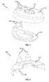
- FIG. 7 shows schematically and exemplarily a further embodiment of a heating system component 700.
- heating unit 720 may be directly attached to carrier unit 110.
- Heating unit 720 exhibits a second cross-section in a direction perpendicular to heating unit's 720 main axis.
- the second cross section corresponds to a hat-like trapezoid with rounded edges.
- a first side 720b of heating unit 720 faces the wet side of carrier unit 110.
- first side 720b of heating unit 720 is essentially planar.
- First side 720b of heating unit 720 is thus essentially in full area contact with the wet side of carrier unit 110.
- Heat produced by heating unit 720 is transferred to the medium to be heated, wherein the medium is arranged on the wet side of carrier unit 110.
- first side 720b of heating unit 720 may be attached to carrier unit 110 by means of laser welding.
- heating unit 720 exhibits a second cross section corresponding to a hat-like trapezoid with rounded edges.
- the hat-like shape may correspond to a bell-like shape.
- edge sections of heating unit 720 delimiting first side 720b comprise wing portions similar to a brimmed hat. These may be manufactured by folding a tube correspondingly before shaping heating unit 720.
- heating unit 720 offers a greater surface area for a laser in order to laser weld heating unit 720 to carrier unit 110. To this extent, laser welding heating unit 720 is less prone to manufacturing errors. Thus, heating system component 700 is more robust because heating unit 720 is solidly attached to the wet side of carrier unit 110, thereby preventing the medium to be heated from entering a space between first side 720b and the wet side of carrier unit 110.
- a list of possible manufacturing methods comprises, but is not limited to, half-automatic assembly and fully-automatic assembly.
- the beveled edge geometry described herein is preferably optimized for an automatic positioning of the temperature monitoring and/or control units. That is, by choosing a bevel angle of preferably 25° to 35°, the bevel surface visible from the direction of the laser beam can be kept sufficiently large so that a possible misalignment of the temperature monitoring and/or control system components can be compensated for.
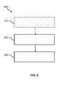
- Fig. 8 shows schematically and exemplarily an embodiment of a method 800 of providing a heating system component for a heating system for heating a fluid medium.
- heating unit 120, 720 that is configured to be in contact with said fluid medium is arranged on a wet side of carrier unit 110, wherein said wet side corresponds to a surface of carrier unit 110 configured to be in contact with said fluid medium.
- heating unit 120, 720 is coupled to said wet side of carrier unit 110, wherein said coupling comprises at least one of a soldering step, a laser welding step, a gluing step, an ultrasonic welding step, and/or a friction welding step.
- an optional step 810 comprises applying a nonstick coating to heating unit 120, 720, wherein coupling heating unit 120, 720 to said wet side of carrier unit 110 comprises gluing heating unit 120, 720 to said wet side of carrier unit 110.
- An example application of the invention generally relates to situations where a fluid medium needs to be heated in an efficient manner, for example in household appliances such as dishwashers, dryers, and washing machines, small electrical appliances such as coffeemakers, irons, steam generators etc. or in water heaters.
- the temperature monitoring and/or control unit may comprise one or more temperature monitoring and/or control elements, such as, e.g., safety devices.
- a single unit or device may fulfill the functions of several items recited in the claims.
- the mere fact that certain measures are recited in mutually different dependent claims does not indicate that a combination of these measures cannot be used to advantage.
- Determinations like measuring a temperature performed by one or several units or devices can be performed by any other number of units or devices.
- measuring a temperature can be performed by a single temperature monitoring and/or control unit or by any other number of different units.
- the determinations and/or the control of the heating system for heating fluid media can be implemented as program code means of a computer program and/or as dedicated hardware.
- a computer program may be stored/distributed on a suitable medium, such as an optical storage medium or a solid-state medium, supplied together with or as part of other hardware, but may also be distributed in other forms, such as via the Internet or other wired or wireless telecommunication systems.
- a suitable medium such as an optical storage medium or a solid-state medium
- the term "computer program” may also refer to embedded software.
- the present invention relates to a heating system component for a heating system for heating a fluid medium, said heating system component comprising: a carrier unit comprising a wet side, wherein said wet side corresponds to a surface of said carrier unit configured to be in contact with said fluid medium; a heating unit arranged on said wet side of said carrier unit and configured to be in contact with said fluid medium; wherein said heating unit is coupled to said carrier unit by means of a coupling step, wherein said coupling step comprises at least one of a soldering step, a laser welding step, a gluing step, an ultrasonic welding step, and/or a friction welding step.
- heating unit (120) comprises a first cross section which is perpendicular to an axial direction of said heating unit (120), wherein said first cross section corresponds to a trapezoid with rounded edges.
- heating unit (720) comprises a first cross section which is perpendicular to an axial direction of said heating unit (720), wherein said first cross section corresponds to a hat-like trapezoid with rounded edges; wherein said hat-like trapezoid with rounded edges preferably corresponds to a bell-like trapezoid with rounded edges.
- thermo monitoring and/or control unit (370, 570a, 570b) comprises a lower part having a beveled edge (571a 1 , 571a 2 , 571b); wherein said beveled edge (571a 1 , 571a 2 , 571b) is adjacent to said lower surface; wherein said beveled edge (571a 1 , 571a 2 , 571b) comprises a bevel angle of less than 90°; wherein said welded seam is located essentially along said beveled edge (571a 1 , 571a 2 , 571 b).
- said coupling means (351) comprise a force-fitting connection mechanism, wherein said force-fitting connection mechanism comprises a force-fitting sealing connection (351); wherein said force-fitting sealing connection (351) preferably comprises at least one of a polyurethane adhesive and/or a silicone adhesive.
- said housing unit (350) preferably comprises a sealing groove (455a), and wherein said heating system component (100, 700) preferably comprises sealing means (455b) configured to be arranged in said sealing groove (455a).
- said coupling means (360, 361, 362, 363) comprise a shape-locking connection mechanism
- said shape-locking connection mechanism comprises shape-locking connection means (360) arranged on an outer surface of said fluid conducting unit (350), a protrusion section (363) arranged on an outer surface of said fluid conducting unit (350), and fixing means (362) configured to engage with said shape-locking connection means (360); wherein said protrusion section (363) is configured to be arranged on said wet side of said carrier unit (110).
- said shape-locking connection means (360) comprise at least one engagement section to engage with said fixing means (362), wherein said at least one engagement section comprises an engagement groove section and an engagement hook section, and wherein said fixing means (362) comprises a second engagement hook section configured to interlock with said engagement groove section and said engagement hook section.
- said fixing means (362) comprise a fixing flange arranged around said circular hole (111) on a dry side of said carrier unit (110), wherein said dry side of said carrier unit (110) is a surface of said carrier unit (110) opposite to said wet side of said carrier unit (110).
- a heating system for heating a fluid medium comprising:
- a household appliance preferably a dishwashing apparatus, comprising a heating system with the features of embodiment 22.
Priority Applications (10)
| Application Number | Priority Date | Filing Date | Title |
|---|---|---|---|
| EP14189693.6A EP3013116A1 (fr) | 2014-10-21 | 2014-10-21 | Composant de système de chauffage et son procédé de production |
| KR1020150146109A KR102387688B1 (ko) | 2014-10-21 | 2015-10-20 | 가열 시스템 구성 요소 및 이의 제조 방법 |
| US14/918,274 US20160109151A1 (en) | 2014-10-21 | 2015-10-20 | Heating system component and method for producing same |
| KR1020150146111A KR20160046742A (ko) | 2014-10-21 | 2015-10-20 | 가열 시스템 구성 요소 및 이의 제조 방법 |
| US14/918,303 US10941962B2 (en) | 2014-10-21 | 2015-10-20 | Heating system component and method for producing same |
| EP15190853.0A EP3013118A1 (fr) | 2014-10-21 | 2015-10-21 | Composant de système de chauffage et son procédé de production |
| CN201510992427.9A CN105526703B (zh) | 2014-10-21 | 2015-10-21 | 加热系统组件及其制造方法 |
| CN201510992140.6A CN105526702A (zh) | 2014-10-21 | 2015-10-21 | 加热系统组件及其制造方法 |
| PL15190848T PL3013117T3 (pl) | 2014-10-21 | 2015-10-21 | Komponent systemu ogrzewania i sposób jego wytwarzania |
| EP15190848.0A EP3013117B1 (fr) | 2014-10-21 | 2015-10-21 | Composant de système de chauffage et son procédé de production |
Applications Claiming Priority (1)
| Application Number | Priority Date | Filing Date | Title |
|---|---|---|---|
| EP14189693.6A EP3013116A1 (fr) | 2014-10-21 | 2014-10-21 | Composant de système de chauffage et son procédé de production |
Publications (1)
| Publication Number | Publication Date |
|---|---|
| EP3013116A1 true EP3013116A1 (fr) | 2016-04-27 |
Family
ID=51743367
Family Applications (3)
| Application Number | Title | Priority Date | Filing Date |
|---|---|---|---|
| EP14189693.6A Withdrawn EP3013116A1 (fr) | 2014-10-21 | 2014-10-21 | Composant de système de chauffage et son procédé de production |
| EP15190853.0A Withdrawn EP3013118A1 (fr) | 2014-10-21 | 2015-10-21 | Composant de système de chauffage et son procédé de production |
| EP15190848.0A Active EP3013117B1 (fr) | 2014-10-21 | 2015-10-21 | Composant de système de chauffage et son procédé de production |
Family Applications After (2)
| Application Number | Title | Priority Date | Filing Date |
|---|---|---|---|
| EP15190853.0A Withdrawn EP3013118A1 (fr) | 2014-10-21 | 2015-10-21 | Composant de système de chauffage et son procédé de production |
| EP15190848.0A Active EP3013117B1 (fr) | 2014-10-21 | 2015-10-21 | Composant de système de chauffage et son procédé de production |
Country Status (5)
| Country | Link |
|---|---|
| US (2) | US20160109151A1 (fr) |
| EP (3) | EP3013116A1 (fr) |
| KR (2) | KR102387688B1 (fr) |
| CN (2) | CN105526703B (fr) |
| PL (1) | PL3013117T3 (fr) |
Cited By (1)
| Publication number | Priority date | Publication date | Assignee | Title |
|---|---|---|---|---|
| DE102017011086A1 (de) | 2017-11-30 | 2019-06-06 | Eichenauer Heizelemente Gmbh & Co. Kg | Beheiztes Pumpengehäuse |
Families Citing this family (13)
| Publication number | Priority date | Publication date | Assignee | Title |
|---|---|---|---|---|
| ITUA20161567A1 (it) * | 2016-03-11 | 2017-09-11 | Irca Spa | Coperchio per pompa centrifuga |
| EP3260796B1 (fr) * | 2016-06-20 | 2020-05-06 | Bleckmann GmbH & Co. KG | Composant de système de chauffage fournissant une conception de capteur de température compact |
| GB2557290B (en) * | 2016-12-05 | 2021-12-22 | Leslie Alexander Gort Barten | Small domestic appliance |
| GB2560176A (en) * | 2017-03-01 | 2018-09-05 | Kenwood Ltd | Beverage making appliance |
| CN107148092B (zh) * | 2017-06-28 | 2023-12-08 | 广东威灵电机制造有限公司 | 加热器 |
| DE102017118217A1 (de) * | 2017-08-10 | 2019-02-14 | Eichenauer Heizelemente Gmbh & Co. Kg | Beheizbares Pumpengehäuseteil |
| DE102017118210A1 (de) * | 2017-08-10 | 2019-02-14 | Eichenauer Heizelemente Gmbh & Co. Kg | Beheizbares Pumpengehäuseteil |
| EP3685953A4 (fr) * | 2017-09-21 | 2021-03-03 | Panasonic Intellectual Property Management Co., Ltd. | Tête de traitement laser et système de traitement laser faisant utilisant celle-ci |
| CN108088083A (zh) * | 2017-12-18 | 2018-05-29 | 珠海格力电器股份有限公司 | 封头组件 |
| EP3561381B1 (fr) * | 2018-04-25 | 2022-08-31 | Bleckmann GmbH & Co. KG | Procédé pour commander un composant de système de chauffage pour un fonctionnement simple et sûr et composant de système de chauffage correspondant |
| IT201800007346A1 (it) * | 2018-07-19 | 2020-01-19 | Riscaldatore elettrico per serbatoio | |
| EP3620097B1 (fr) * | 2018-09-07 | 2021-08-25 | Bleckmann GmbH & Co. KG | Système de chauffage destiné à chauffer un milieu fluide |
| CN116696833B (zh) * | 2022-03-16 | 2024-03-19 | 贝克电热科技(深圳)有限公司 | 一种刀片加热式的加热泵盖及加热泵 |
Citations (6)
| Publication number | Priority date | Publication date | Assignee | Title |
|---|---|---|---|---|
| DE1299379B (de) * | 1965-04-22 | 1969-07-17 | Siemens Elektrogeraete Gmbh | Elektrisch beheizter Fluessigkeitsbehaelter |
| GB2310360A (en) * | 1996-02-24 | 1997-08-27 | D H Haden Plc | Heating vessel |
| EP0848576A2 (fr) * | 1996-12-09 | 1998-06-17 | Sheathed Heating Elements Limited | Dispositif de chauffage électrique |
| DE19852569A1 (de) * | 1998-11-13 | 2000-05-18 | Miele & Cie | Umwälzpumpe, insbesondere für wasserführnde Haushaltgeräte |
| EP1238614A1 (fr) * | 2001-03-07 | 2002-09-11 | Fritz Eichenauer GmbH & Co. KG | Cartouche de chauffage pour un récipient de cuisson chauffé électriquement |
| US20060236999A1 (en) | 2005-04-21 | 2006-10-26 | Bleckmann Gmbh & Co. Kg | Heated pump with boiling protection |
Family Cites Families (27)
| Publication number | Priority date | Publication date | Assignee | Title |
|---|---|---|---|---|
| US848576A (en) * | 1907-01-15 | 1907-03-26 | Augustus W Stephens | Bottle opener and stopper. |
| US1238614A (en) * | 1917-07-05 | 1917-08-28 | Wood Newspaper Mach Corp | Web-press. |
| US1299379A (en) * | 1918-07-26 | 1919-04-01 | Robert J Owens | Wild-oat and barley separator. |
| US1808109A (en) * | 1928-10-24 | 1931-06-02 | John O Heinze | Motor vehicle |
| US2338632A (en) * | 1941-05-12 | 1944-01-04 | Elmer D Frazier | Corn planter |
| CA1092634A (fr) * | 1977-10-18 | 1980-12-30 | Alvin Thomas | Poele a frire electrique |
| CA1202659A (fr) | 1984-06-07 | 1986-04-01 | Ronal C. Du Pont | Bouilloire electrique |
| US4908501A (en) * | 1988-10-19 | 1990-03-13 | Arnold Iii Morris A | Portable electrically heated animal drinking water container |
| GB2338632A (en) | 1998-06-16 | 1999-12-22 | Pifco Ltd | Metal sheathed planar element: Edge connector with shutter |
| CN2394399Y (zh) * | 1999-09-22 | 2000-08-30 | 斯特里克斯有限公司 | 电加热器 |
| US6486446B1 (en) | 2001-10-15 | 2002-11-26 | Yao-Tsung Kao | Combination of a bottom of a pan and a heating means |
| GB0321916D0 (en) * | 2003-09-19 | 2003-10-22 | Heatsafe Cable Systems Ltd | Self-regulating electrical heating cable |
| US20080087234A1 (en) * | 2004-07-05 | 2008-04-17 | Lasag Ag | Water Heater or Steam Generator |
| WO2007034343A1 (fr) * | 2005-09-19 | 2007-03-29 | Koninklijke Philips Electronics N.V. | Dispositif permettant de preparer une boisson et comprenant un chauffe-eau |
| ITVE20060001U1 (it) * | 2006-01-12 | 2007-07-13 | I R C A S P A Ind Resistenze Corazzate ... | Contenitore per fluidi da riscaldare |
| CN101116886A (zh) | 2006-08-04 | 2008-02-06 | 捷飞有限公司 | 均温板的制造方法 |
| JP5435187B2 (ja) * | 2007-06-13 | 2014-03-05 | 株式会社Ihi | 鋼床版及び鋼床版の製造方法 |
| LT2430878T (lt) * | 2009-05-11 | 2022-11-10 | Wilhelm Zimmerer | Elektrinis paviršiaus šildymo įrenginys, jo gamybos būdas ir medžiaga |
| DE102009057997A1 (de) * | 2009-12-11 | 2011-06-22 | Daimler AG, 70327 | Verfahren zum Verschweißen von zwei Metallbauteilen |
| EP2338656A1 (fr) * | 2009-12-23 | 2011-06-29 | Borealis AG | Polypropylène hétérophasique avec équilibre amélioré entre la raideur et la transparence |
| ITFI20100112A1 (it) * | 2010-05-21 | 2011-11-22 | Koninkl Philips Electronics Nv | "dispositivo per il riscaldamento di acqua e la produzione di vapore" |
| EP2407069A1 (fr) * | 2010-07-12 | 2012-01-18 | Bleckmann GmbH & Co. KG | Chauffe-eau instantané dynamique |
| FR2967563B1 (fr) * | 2010-11-19 | 2013-08-23 | Seb Sa | Procede d'obtention d'un recipient de cuisson comportant une face exterieure anodisee dure coloree |
| CN202018118U (zh) * | 2011-04-07 | 2011-10-26 | 畅国帏 | 一种温水加热器 |
| CN102297506B (zh) | 2011-08-12 | 2013-04-24 | 杭州热威机电有限公司 | 和泵相结合的加热器 |
| CN102430867A (zh) | 2011-09-17 | 2012-05-02 | 宋广科 | 船体合拢装配新方法 |
| GB2539226B (en) | 2015-06-10 | 2018-04-04 | Yao Tsung Kao | Combination method of heating device of pot/kettle |
-
2014
- 2014-10-21 EP EP14189693.6A patent/EP3013116A1/fr not_active Withdrawn
-
2015
- 2015-10-20 US US14/918,274 patent/US20160109151A1/en not_active Abandoned
- 2015-10-20 KR KR1020150146109A patent/KR102387688B1/ko active IP Right Grant
- 2015-10-20 KR KR1020150146111A patent/KR20160046742A/ko not_active Application Discontinuation
- 2015-10-20 US US14/918,303 patent/US10941962B2/en active Active
- 2015-10-21 CN CN201510992427.9A patent/CN105526703B/zh active Active
- 2015-10-21 PL PL15190848T patent/PL3013117T3/pl unknown
- 2015-10-21 CN CN201510992140.6A patent/CN105526702A/zh active Pending
- 2015-10-21 EP EP15190853.0A patent/EP3013118A1/fr not_active Withdrawn
- 2015-10-21 EP EP15190848.0A patent/EP3013117B1/fr active Active
Patent Citations (6)
| Publication number | Priority date | Publication date | Assignee | Title |
|---|---|---|---|---|
| DE1299379B (de) * | 1965-04-22 | 1969-07-17 | Siemens Elektrogeraete Gmbh | Elektrisch beheizter Fluessigkeitsbehaelter |
| GB2310360A (en) * | 1996-02-24 | 1997-08-27 | D H Haden Plc | Heating vessel |
| EP0848576A2 (fr) * | 1996-12-09 | 1998-06-17 | Sheathed Heating Elements Limited | Dispositif de chauffage électrique |
| DE19852569A1 (de) * | 1998-11-13 | 2000-05-18 | Miele & Cie | Umwälzpumpe, insbesondere für wasserführnde Haushaltgeräte |
| EP1238614A1 (fr) * | 2001-03-07 | 2002-09-11 | Fritz Eichenauer GmbH & Co. KG | Cartouche de chauffage pour un récipient de cuisson chauffé électriquement |
| US20060236999A1 (en) | 2005-04-21 | 2006-10-26 | Bleckmann Gmbh & Co. Kg | Heated pump with boiling protection |
Cited By (2)
| Publication number | Priority date | Publication date | Assignee | Title |
|---|---|---|---|---|
| DE102017011086A1 (de) | 2017-11-30 | 2019-06-06 | Eichenauer Heizelemente Gmbh & Co. Kg | Beheiztes Pumpengehäuse |
| DE102017011086B4 (de) | 2017-11-30 | 2023-07-06 | Eichenauer Heizelemente Gmbh & Co. Kg | Beheiztes Pumpengehäuse |
Also Published As
| Publication number | Publication date |
|---|---|
| CN105526702A (zh) | 2016-04-27 |
| CN105526703A (zh) | 2016-04-27 |
| US10941962B2 (en) | 2021-03-09 |
| KR20160046741A (ko) | 2016-04-29 |
| US20160109152A1 (en) | 2016-04-21 |
| KR20160046742A (ko) | 2016-04-29 |
| US20160109151A1 (en) | 2016-04-21 |
| EP3013117B1 (fr) | 2021-08-11 |
| EP3013117A1 (fr) | 2016-04-27 |
| CN105526703B (zh) | 2021-06-04 |
| KR102387688B1 (ko) | 2022-04-18 |
| PL3013117T3 (pl) | 2022-01-17 |
| EP3013118A1 (fr) | 2016-04-27 |
Similar Documents
| Publication | Publication Date | Title |
|---|---|---|
| US10941962B2 (en) | Heating system component and method for producing same | |
| US20170261232A1 (en) | Heating system component and method for producing same | |
| JP6925352B2 (ja) | 遠心ポンプ用カバー | |
| JP5155109B2 (ja) | 電気ケトル | |
| US11287161B2 (en) | Heating system component providing a compact temperature sensor design | |
| EP2960594A1 (fr) | Composant de système de chauffage et son procédé de production | |
| JP4951080B2 (ja) | 配管ろう付け時の過剰温度検知方法及び流体制御機器 | |
| CN109386504A (zh) | 可加热的泵壳体件 | |
| US20170015447A1 (en) | Heater structure for packing machine | |
| CN114909335B (zh) | 泵盖、加热泵和家用电器 | |
| US20230228453A1 (en) | Heating pump cover and heating pump | |
| WO2016097980A1 (fr) | Chauffe-eau à chauffage électrique | |
| EP1731080A1 (fr) | Dispositif pour chauffer l'eau, particulièrement pour l'eau dans les lave-vaisselles | |
| KR20230155911A (ko) | 히터의 제조방법, 히터 및 이를 포함하는 물 가열 장치 | |
| CN110848817A (zh) | 散热器、空调器及散热器的安装方法 | |
| CN112629007A (zh) | 加热装置和具有该加热装置的泵 | |
| CN109642734A (zh) | 具有连接元件的家用器具 | |
| JP2001346680A (ja) | 炊飯器 |
Legal Events
| Date | Code | Title | Description |
|---|---|---|---|
| PUAI | Public reference made under article 153(3) epc to a published international application that has entered the european phase |
Free format text: ORIGINAL CODE: 0009012 |
|
| AK | Designated contracting states |
Kind code of ref document: A1 Designated state(s): AL AT BE BG CH CY CZ DE DK EE ES FI FR GB GR HR HU IE IS IT LI LT LU LV MC MK MT NL NO PL PT RO RS SE SI SK SM TR |
|
| AX | Request for extension of the european patent |
Extension state: BA ME |
|
| STAA | Information on the status of an ep patent application or granted ep patent |
Free format text: STATUS: THE APPLICATION IS DEEMED TO BE WITHDRAWN |
|
| 18D | Application deemed to be withdrawn |
Effective date: 20161028 |