EP3012028A1 - Kolbendosierer für fluide Medien und System zum Beschichten von Gegenständen - Google Patents
Kolbendosierer für fluide Medien und System zum Beschichten von Gegenständen Download PDFInfo
- Publication number
- EP3012028A1 EP3012028A1 EP14003631.0A EP14003631A EP3012028A1 EP 3012028 A1 EP3012028 A1 EP 3012028A1 EP 14003631 A EP14003631 A EP 14003631A EP 3012028 A1 EP3012028 A1 EP 3012028A1
- Authority
- EP
- European Patent Office
- Prior art keywords
- piston
- input
- output
- piston member
- dispenser
- Prior art date
- Legal status (The legal status is an assumption and is not a legal conclusion. Google has not performed a legal analysis and makes no representation as to the accuracy of the status listed.)
- Granted
Links
- 238000000576 coating method Methods 0.000 title claims abstract description 22
- 239000011248 coating agent Substances 0.000 title claims abstract description 21
- 239000012530 fluid Substances 0.000 title claims abstract description 16
- 238000011049 filling Methods 0.000 claims abstract description 18
- 230000008878 coupling Effects 0.000 claims description 33
- 238000010168 coupling process Methods 0.000 claims description 33
- 238000005859 coupling reaction Methods 0.000 claims description 33
- 230000000295 complement effect Effects 0.000 claims description 7
- 238000009413 insulation Methods 0.000 claims description 7
- 239000003973 paint Substances 0.000 description 35
- 239000000463 material Substances 0.000 description 12
- 238000000034 method Methods 0.000 description 9
- 239000003795 chemical substances by application Substances 0.000 description 8
- 238000007667 floating Methods 0.000 description 6
- 238000011010 flushing procedure Methods 0.000 description 6
- 239000003599 detergent Substances 0.000 description 5
- 230000000903 blocking effect Effects 0.000 description 4
- 230000002349 favourable effect Effects 0.000 description 3
- 238000002955 isolation Methods 0.000 description 3
- 238000007789 sealing Methods 0.000 description 3
- 239000004020 conductor Substances 0.000 description 2
- 238000005516 engineering process Methods 0.000 description 2
- 239000007788 liquid Substances 0.000 description 2
- 230000004048 modification Effects 0.000 description 2
- 238000012986 modification Methods 0.000 description 2
- 238000000926 separation method Methods 0.000 description 2
- 239000002966 varnish Substances 0.000 description 2
- 241001136792 Alle Species 0.000 description 1
- 241000282887 Suidae Species 0.000 description 1
- 238000004140 cleaning Methods 0.000 description 1
- 238000010276 construction Methods 0.000 description 1
- 239000012777 electrically insulating material Substances 0.000 description 1
- 239000011521 glass Substances 0.000 description 1
- 239000004922 lacquer Substances 0.000 description 1
- 238000011068 loading method Methods 0.000 description 1
- 239000012811 non-conductive material Substances 0.000 description 1
- 239000007921 spray Substances 0.000 description 1
Images




Classifications
-
- B—PERFORMING OPERATIONS; TRANSPORTING
- B05—SPRAYING OR ATOMISING IN GENERAL; APPLYING FLUENT MATERIALS TO SURFACES, IN GENERAL
- B05B—SPRAYING APPARATUS; ATOMISING APPARATUS; NOZZLES
- B05B5/00—Electrostatic spraying apparatus; Spraying apparatus with means for charging the spray electrically; Apparatus for spraying liquids or other fluent materials by other electric means
- B05B5/16—Arrangements for supplying liquids or other fluent material
- B05B5/1608—Arrangements for supplying liquids or other fluent material the liquid or other fluent material being electrically conductive
- B05B5/1675—Arrangements for supplying liquids or other fluent material the liquid or other fluent material being electrically conductive the supply means comprising a piston, e.g. a piston pump
Definitions
- the invention relates to a system for coating objects with an application device, which is connected to at least one piston dispenser.
- piston dispensers In order to be able to supply the application device with paint and detergent in a well-dosed manner, piston dispensers have established themselves on the market, among other things. There, the working space of the cylinder is filled with paint and this then fed to the application device. Rinsing of the piston dispenser and the lines leading to the application device, which is necessary before a color change, takes place by means of a rinsing agent supplied from another source. However, this can lead to relatively large paint losses and a relatively large need for washing-up liquid, which can be counteracted again, for example, by the above-mentioned pigging technique.
- the pigging technology can in particular meet another, particularly important condition for safety reasons: In coatings with electrostatically operating application devices, it must be ensured that between application device and one at ground potential lying detergent reservoir or paint reservoir or color changer, as they are known per se, a potential separation is ensured at any time. This is achieved in the pigging technology by an insulating air layer is constructed in the one or more leads from the detergent reservoir or from the ink reservoir or color changer to the piston dispenser, wherein the piston dispenser itself is at the potential of the application device.
- a space between two piston elements is used as the working space and the supply of material from a source into this working space and the removal of material from this working space out to the application device can be effected by channels in these two piston elements.
- a volume of material between the two piston elements is set, so that the material can be dispensed well dosed to the application device.
- the piston assembly as a moving unit between a first position in which the input piston member occupies its filling position., And a second position in which the output piston member assumes its dispensing position, movable in the interior.
- the piston assembly can be moved as a whole, wherein it carries the introduced material volume with it.
- an insulation space can be formed, which is filled with an electrically insulating insulating medium.
- the isolation medium is preferably air. This can For example, take place when the piston assembly is moved as a moving unit in the direction of the output terminal.
- the input piston member comprises a coupling portion which is complementary to a coupling recess formed on an input side of the piston meter and / or the output piston member comprises a coupling portion which is complementary to a coupling recess formed on an output side of the piston meter.
- the piston dispenser may be assembled from prefabricated components when the input port is formed on an input block on an input side of the piston dispenser and / or the output port is formed on an output block on an output side of the piston dispenser.
- the input connection is formed on an input section of the cylinder unit.
- the input port is then formed on the wall of the cylinder unit.
- a favorable arrangement of the drive for the piston elements is when the input piston member and / or the output piston member is floatingly mounted.
- a thrust medium such as compressed air, can be used for propulsion and for the movement of the piston assembly.
- the input piston element may be coupled to a piston rod which is movable by means of a piston drive provided outside the cylinder unit.
- the output piston element is then stored floating.
- At least one locking device is provided, by means of which the input piston element in its filling position and / or the output piston element in its dispensing position at least in the direction of the longitudinal axis the piston dispenser is lockable.
- the piston dispenser is a piston dispenser with some or all of the features explained above.
- the potential isolation seizes when the application device works electrostatically.
- FIG. 1 schematically a system 10 for applying coating media is referred to, which comprises an application device 12.
- a coating system 10 for paints will be described by way of example.
- the application device may be, for example, a spray gun or a high-rotation atomizer, as is known per se.
- the coating system 10 comprises a first piston dispenser 16 and a second piston dispenser 18.
- the piston dispensers 16 and 18 are identical in construction in the present embodiment; In the following, therefore, only the piston feeder 16 will be explained in detail. The above applies mutatis mutandis to the piston dispenser 18th
- the piston dispenser 16 is illustrated in various phases of operation of the coating system 10, wherein only in FIG. 2 all components of the piston cylinder 16 are provided with reference numerals.
- the piston dispenser 16 is made of an electrically non-conductive material and comprises a cylinder unit 20 with a hollow cylinder 20 a, which is made in the present embodiment of glass or plastic.
- the cylinder unit 20 comprises at a first end side on an inlet side 22 of the piston meter 16 an inlet block 24 and at its opposite end on an outlet side 26 of the piston meter 16 an output block 28, so that an inner space 30 of the piston meter 16 is limited.
- a the inner space 30 facing cylindrical coupling recesses 32 and 34 respectively formed with a connection bottom 36 and 38, coaxial with the longitudinal axis 40th the cylinder unit 20 and the piston meter 16 are arranged.
- the longitudinal axis 40 is only in FIG. 2 shown in dashed lines.
- an input channel 44 extends coaxially to the longitudinal axis 40 and opens at the input side 42 into an input port 46.
- a control line 48 which extends adjacent to the input channel 44 and opens at the input side 42 in a control terminal 50.
- an output channel 54 which extends coaxially to the longitudinal axis 40 and opens at the output side 52 into an output port 56.
- the output block 26 also has a control line 58 which extends adjacent to the output channel 54 and extends between the coupling bottom 38 of the output block 26 and a control terminal 60 at its output side 52.
- a piston assembly 62 with an input piston member 64 and an output piston member 66, which are formed in the present embodiment as a floating input piston 68 and as floating output piston 70.
- the input piston 68 comprises a cylindrical coupling portion 72 which is complementary to the coupling recess 32 in the input block 24 and can dip into it.
- the coupling portion 72 of the input piston 68 merges into a piston body 74, which is complementary to the interior 30 of the piston meter 16 and sealingly abuts against its inner circumferential surface.
- the input piston 68 has a passage-flow channel 76 which extends from the free end face 78 of the coupling portion 72 to the free end face 80 of the piston body 74 and at the coupling portion 72 has a connection opening 82 which is coaxial with the longitudinal axis 40 and complementary to the input channel 44th is at the coupling bottom 36 of the input block 24.
- a valve seat 84 is formed, which cooperates with a sealing element 86 of a control valve 88, as it is known per se and which is accommodated in a valve receiving space 90 in the piston body 74.
- the control valve 88 is configured such that it must be acted upon by a control signal, so that the sealing element 86 occupies a release position and the flow channel 76 releases.
- Such a release configuration of the control valve 88 shows FIG. 3
- the sealing element 86 of the control valve 88 assumes a blocking position in which the flow channel 76 is blocked on the valve seat 84; such a blocking configuration of the control valve 88 is illustrated FIG. 2 ,
- control valve 88 can be acted upon with a control signal, runs in the input piston 68, a valve control line 92 which extends from the valve receiving space 88 and opens into a ring line 94 which is provided on the free end face 78 of the coupling portion 72.
- This ring line 94 is coaxial with the longitudinal axis 40 and extends with a ring radius corresponding to the distance between the input channel 44 and the position of the control line 48 at the coupling bottom 36 of the input block 24.
- the control line 48 of the input block 24 comes into contact with the ring line 94 when the input piston 68 occupies a filling position in which the coupling portion 72 dips into the coupling recess 32 in the input block 24, as it FIG. 2 illustrated.
- the control terminal 50 at the input block 24 is connected to a signal source 96.
- the control valve 88 operates pneumatically and as a control signal a control fluid and concrete compressed air is used.
- the control line 48 in the input block 24 and the valve control line 92 in the input piston 68 are therefore designed as fluidic lines and the ring line 94 as an annular groove 98.
- the signal source 96 in this case is correspondingly a control fluid source in the form of a compressed air source 100a.
- a corresponding signal source 96 in the form of a compressed air source 100b is also connected to the output control block 60 at the output block 28.
- an electrically operating control valve 88 may also be used; In this case, an electrical signal is used as the control signal for the control valve 88 and the control lines 48, 92 and 94 are electrical lines.
- the piston dispenser 16 also comprises a locking device 102a for the input piston 68, so that it can be locked in its filling position at least in the axial direction immovably.
- a locking device 102a for the input piston 68, so that it can be locked in its filling position at least in the axial direction immovably.
- the coupling portion 72 of the input piston 68 on its outer circumferential surface on a circumferential locking groove 104, in which a locking pin 106 can retract from the lateral surface of the coupling recess 32 of the input block 24.
- the locking pin 106 is in the FIGS.
- the output piston 70 is identical to the input piston 68 and the components of the output piston 70 bear the same reference numerals as the corresponding components in the input piston 68.
- the output piston 70 is arranged in the interior 30 of the piston meter 16 that its coupling portion 72 from the input piston 68.
- the output piston 70 assumes a dispensing position.
- the piston dispenser 16 also includes a locking device 102b for the output piston 70, so that it can be locked in its delivery position at least in the axial direction immovably.
- a locking device 102b for the output piston 70 comprises a locking pin 106b, which in the locking groove 104 of the output piston 70 can intervene. If the output piston 70 is in its dispensing position and the locking pin 106b is retracted into the locking groove 104 of the output piston 70, this can not be moved axially.
- an electrically operating control valve 88 may be used. The same applies mutatis mutandis to the input piston 68.
- the output port 56 is connected at the output block 28 of the piston dispenser 16 via a line 108 to a valve device 110 of the application device 12, which is connected via a further line 112 and in the same manner with the second piston dispenser 18.
- Valve device 110 is also connected via a flushing agent line 114 to a flushing agent source 116 and via a compressed air line 118 to a compressed air source 120.
- the input port 46 on the input block 24 of the piston dispenser 16 is connected via a line 122 to a color change unit 124 which may be fed from ring lines 126 with different paints, from a flushing agent source 128 with rinsing agent and from a compressed air source 130 with compressed air and also comprises an outlet line 132 as it is known in and of itself.
- a color change unit 124 may be fed from ring lines 126 with different paints, from a flushing agent source 128 with rinsing agent and from a compressed air source 130 with compressed air and also comprises an outlet line 132 as it is known in and of itself.
- FIG. 1 only two ring lines 126 are designated.
- Another such color changing unit 134 is connected to the piston feeder 18 via a conduit 136 in the same manner.
- the components of the color changing unit 134 are not specifically provided with reference numerals.
- control line 48 of the input block 24 is supplied with compressed air from the compressed air source 100a, whereby the control valve 88 of the input piston 68 occupies its release configuration.
- a certain color is now conveyed by the color changing unit 124 in the input channel 44 of the input block 24, which then flows through the passage flow channel 76 of the input piston 68 and exits at the free end face 80 of the piston body 74.
- lacquer is dotted and illustrates the flow direction of the paint by an arrow with a solid line.
- the flow of compressed air is indicated by an arrow with three circles.
- the control valve 88 of the output sump 70 in its blocking configuration now prevents paint from flowing through its passage flow passage 76, and therefore the output piston 70 is pushed away from the input piston 68 by the paint.
- a working space 1-38 which forms in the FIGS. 3 to 5 can be seen and its volume depends on the amount of medium contained therein.
- the working space 138 is thus formed at least temporarily.
- the amount of paint required for a vehicle body roof to be painted in its own color may be less than the amount of paint of a different color required for the side area of a vehicle body.
- FIG. 4 Also illustrates, via the color changing unit 124 from the compressed air source 130 compressed air to the input port 46 of the input block 24 given.
- the compressed air which acts as a thrust medium
- the entire conveyor assembly 142 pushed in the direction of the output block 28 until the coupling portion 72 of the output piston 70 dips into the coupling recess 34 of the output block 28 and the output piston 70 assumes its dispensing position in which the output piston 70 is locked by the locking device 102 b.
- the piston assembly 62 can thus be moved in the interior 30 as a movement unit between a first position in which the input piston 68 assumes its filling position, and a second position in which the output piston 70 assumes its dispensing position.
- an insulation space 144 is formed, which is filled with an electrically insulating insulation medium, which in the present case is provided by compressed air. This shows FIG. 5 ,
- the application device 12 to be operated with high voltage and for high voltage to be applied to the output side 26 of the piston dosing device 16 without the danger of a voltage flashover in the direction of the color change unit 124.
- FIG. 7 illustrates how then a thrust medium, for example, compressed air from the compressed air source 120, via the valve means 110 on the line 108 and in this way on the output terminal 56 at the output block 28 is given.
- the locking device 102b releases the output piston 70, whereupon it moves together with the input piston 68 in the direction of the input block 24 until again in the FIGS. 1 and 2 Filling basic configuration of the piston dispenser 16 is reached.
- a second insulation space 146 is thereby formed, which with an isolation medium is filled, which in the present case is given by the compressed air.
- paint from the second piston dispenser 18 can be dispensed in parallel and high voltage applied to the application device 12.
- the second piston dispenser 18 was filled with a paint for this purpose in the manner explained above, while the paint from the piston dispenser 16 was applied.
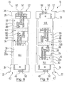
- FIGS. 8 and 9 illustrate briefly the operating situations according to the FIGS. 6 and 7 with the difference that a larger amount of paint 140 was pressed into the working space 138, as required for the actual application process to carry a kind of security volume.
- the assembly of input piston 68, output piston 70 and paint 140 is moved together to the input block 24 after the application process. Then, first the control valve 88 is brought in the input piston 68 in its release configuration and the paint 140 is pressed via the line 122 and the color change unit 124 back into the associated ring line 126 by compressed air against the output side 26 of the piston dispenser 16 forth against the output piston 70 is pressed ,
- FIGS. 10 and 11 illustrate a piston dispenser 16 according to a second embodiment, in which the above-described components carry the same reference numerals.
- the input piston member 64 is not a floatingly mounted input piston 68, but an input piston 150 coupled to a piston rod 148.
- the piston rod 148 is made of an electrically insulating material and extends through a guide passage 152 in the input block 24 It can be moved to the outside and can be moved by means of a provided outside the cylinder unit 20 piston drive 154, as is in itself known and therefore not further explained.
- the piston rod 148 is coaxial with the input piston 150, correspondingly the input port 44 and the input port 46 of the input block 24 are arranged eccentrically, including the position of the connection port 82 and the course of the passage block. Flow channel 76 of the input piston 68 are adjusted.
- FIGS. 12 and 13 Once again show a modification of the piston dispenser 16 with piston rod 148.
- the input channel 44 with input port 46 and the control line 48 with control port 50 are not provided in an input block 24, but in an input section 156 of the cylinder unit 20 on the input side 42 of the piston meter 16.
- the connection opening 82 and the passage of the passage flow channel 76 of the input piston 68 are adapted accordingly, wherein the connection opening 82 is formed as a radially circumferential connection groove 158, so that the fluid connection of the lines can be achieved independently of the rotational position of the input piston 150.
- FIGS. 12 and 13 it may be necessary to dispense with a coupling portion 72 in the input piston 68.
- the locking device 102 a, in the FIGS. 12 and 13 is not shown specifically, then at least according to radially arranged on the hollow cylinder 20a.
Landscapes
- Coating Apparatus (AREA)
- Reciprocating Pumps (AREA)
Abstract
Description
- Die Erfindung betrifft einen Kolbendosierer für fluide Medien, insbesondere zur Versorgung einer elektrostatisch arbeitenden Applikationseinrichtung in einer Anlage zur Beschichtung von Gegenständen, mit
- a) einer Zylindereinheit mit einem Innenraum, in dem zumindest zeitweise ein Arbeitsraum ausbildbar ist;
- b) einer Kolbenanordnung, die in dem Innenraum bewegbar ist;
wobei - c) die Zylindereinheit einen Eingangsanschluss, über welchen dem Arbeitsraum fluides Medium zuführbar ist, und einen Ausgangsanschluss aufweist, über welchen fluides Medium aus dem Arbeitsraum abgebbar ist.
- Außerdem betrifft die Erfindung ein System zum Beschichten von Gegenständen mit einer Applikationseinrichtung, welche mit wenigstens einem Kolbendosierer verbunden ist.
- Bei Beschichtungsanlagen, insbesondere bei Lackieranlagen, werden häufig Applikationseinrichtungen eingesetzt, welche das von ihnen zu versprühende Beschichtungsmaterial mittels einer Hochspannungselektrode ionisieren. Dieses ionisierte Material wird dann auf Grund elektrostatischer Kräfte auf zu beschichtende Gegenstände gezogen, welche hierzu im Allgemeinen auf Massepotential liegen. Als zu beschichtende Gegenstände seien beispielhaft Fahrzeugkarosserien und Bauteile von Fahrzeugen genannt.
- Bei Lackieranlagen kommt es häufig vor, dass für die Beschichtung eines Gegenstandes ein anderer Lack verwendet werden soll als derjenige Lack, mit dem ein vorhergehender Gegenstand beschichtet wurde. Vor einem Lackwechsel müssen die zur Applikationseinrichtung führenden Leitungen und das Versorgungssystem für den Lack mit einem Spülmittel gespült und von Lackresten des ersten Lacks befreit werden.
- Bei einem Lackwechsel kommt es zwangsläufig zu Lackverlusten und es wird eine Menge an Spülmittel verbraucht, die jeweils anlagenspezifisch ist. Um die Lackverluste und den Spülmittelbedarf möglichst gering zu halten, wurde beispielsweise die so genannte Molchtechnik entwickelt, bei welcher Lack und Spülmittel mittels Molchen voneinander getrennt gehalten werden können. Diese Technik ist jedoch verhältnismäßig aufwendig.
- Um der Applikationseinrichtung Lack und Spülmittel wohldosiert zuführen zu können, haben sich am Markt unter anderem Kolbendosierer etabliert. Dort wird der Arbeitsraum des Zylinders mit Lack gefüllt und dieser dann der Applikationseinrichtung zugeführt. Ein Spülen des Kolbendosierers und der zur Applikationseinrichtung führenden Leitungen, welches vor einem Farbwechsel notwendig ist, erfolgt mittels eines aus einer anderen Quelle zugeführten Spülmittels. Hierdurch kann es jedoch zu verhältnismäßig großen Lackverlusten und einem verhältnismäßig großen Spülmittelbedarf kommen, denen wieder beispielsweise durch die oben angesprochene Molchtechnik entgegengewirkt werden kann.
- Die Molchtechnik kann insbesondere einer anderen, aus Sicherheitsgründen besonders wichtigen Bedingung gerecht werden: Bei Beschichtungen mit elektrostatisch arbeitenden Applikationseinrichtungen muss gewährleistet sein, dass zwischen Applikationseinrichtung und einem auf Erdpotential liegenden Spülmittelreservoir bzw. Farbreservoir oder Farbwechsler, wie sie an und für sich bekannt sind, zu jedem Zeitpunkt eine Potentialtrennung sichergestellt ist. Dies wird bei der Molchtechnik erreicht, indem in der oder den Zuleitungen vom Spülmittelreservoir bzw. vom Farbreservoir oder Farbwechsler zum Kolbendosierer eine isolierende Luftschicht aufgebaut wird, wobei der Kolbendosierer selbst auf dem Potential der Applikationseinrichtung liegt.
- Falls dabei jedoch nicht alles elektrisch leitende Material, sei es Lack oder Spülmittel, zuverlässig aus der Leitung verdrängt wird, oder solch leitfähiges Material auf Grund einer nicht sofort erkannten Undichtigkeit im Kolbendosierer in den Isolationsraum gelangt, kann es zu elektrischen Überschlägen kommen.
- Darüber hinaus erhöht das aus den Zuleitungen zum Kolbendosierer entfernte Material den Gesamtverbrauch an Material, der für einen Farbwechsel notwendig ist.
- Es ist nun Aufgabe der Erfindung, einen Kolbendosierer und ein System der eingangs genannten Art bereitzustellen, bei welchem der Materialverlust bei einem Farbwechsel möglichst gering ausfällt.
- Diese Aufgabe wird bei einem Kolbendosierer der eingangs genanriten Art dadurch gelöst, dass
- d) die Kolbenanordnung ein Eingangskolbenelement und ein Ausgangskolbenelement umfasst, zwischen denen der Arbeitsraum ausbildbar ist;
- e) das Eingangskolbenelement einen Durchgangs-Strömungskanal umfasst und in eine Befüllstellung bewegbar ist, in welcher der Durchgangs-Strömungskanal fluidisch mit dem Eingangsanschluss verbunden ist, so dass fluides Medium zwischen das Eingangskolbenelement und das Ausgangskolbenelement förderbar ist, wodurch sich der Arbeitsraum ausbildet;
- f) das Ausgangskolbenelement einen Durchgangs-Strömungskanal umfasst und in eine Abgabestellung bewegbar ist, in welcher der Durchgangs-Strömungskanal fluidisch mit dem Ausgangsanschluss verbunden ist.
- Erfindungsgemäß wird also ein Raum zwischen zwei Kolbenelementen als Arbeitsraum genutzt und die Zufuhr von Material aus einer Quelle in diesen Arbeitsraum hinein und die Abfuhr von Material aus diesem Arbeitsraum heraus zur Applikationseinrichtung kann durch Kanäle in diesen beiden Kolbenelementen erfolgen. Hierdurch wird ein Materialvolumen zwischen den beiden Kolbenelementen festgelegt, so dass das Material wohldosiert an die Applikationseinrichtung abgegeben werden kann.
- Vorzugsweise ist die Kolbenanordnung als Bewegungseinheit zwischen einer ersten Stellung, in welcher das Eingangskolbenelement seine Befüllstellung einnimmt., und einer zweiten Stellung, in welcher das Ausgangskolbenelement seine Abgabestellung einnimmt, im Innenraum bewegbar. So kann nach dem Befüllen des Arbeitsraumes zwischen den Kolbenelementen die Kolbenanordnung als Ganzes bewegt werden, wobei sie das eingebrachte Materialvolumen mit sich führt.
- Insbesondere die oben angesprochene Potentialtrennung kann sicher aufrecht erhalten werden, wenn im Innenraum des Kolbendosierers zwischen dem Eingangsanschluss und dem Eingangskolbenelement ein Isolationsraum ausbildbar ist, der mit einem elektrisch isolierenden Isolationsmedium gefüllt ist. Das Isolationsmedium ist vorzugsweise Luft. Dies kann beispielsweise erfolgen, wenn die Kolbenanordnung als Bewegungseinheit in Richtung auf den Ausgangsanschluss bewegt wird.
- Es ist verbindungstechnisch von Vorteil, wenn das Eingangskolbenelement einen Koppelabschnitt umfasst, welcher komplementär zu einer Koppelvertiefung an einer Eingangsseite des Kolbendosierers ausgebildet ist und/oder das Ausgangskolbenelement einen Koppelabschnitt umfasst, welcher komplementär zu einer Koppelvertiefung an einer Ausgangsseite des Kolbendosierers ausgebildet ist.
- Der Kolbendosierer kann vorteilhaft aus vorgefertigten Einzelteilen montiert werden, wenn der Eingangsanschluss an einem Eingangsblock an einer Eingangsseite des Kolbendosierers und/oder der Ausgangsanschluss an einem Ausgangsblock an einer Ausgangsseite des Kolbendosierers ausgebildet ist.
- Alternativ zu einer Lackzuführung in axialer Richtung des Kolbendosierer kann es günstig sein, wenn der Eingangsanschluss an einem Eingangsabschnitt der Zylindereinheit ausgebildet ist. Der Eingangsanschluss ist dann an der Wand der Zylindereinheit ausgebildet.
- Eine vom Antrieb für die Kolbenelemente günstige Anordnung liegt vor, wenn das Eingangskolbenelement und/oder das Ausgangskolbenelement schwimmend gelagert ist. Bei einem schwimmend gelagerten Kolbenelement kann ein Schubmedium, wie beispielsweise Druckluft, zum Vortrieb und für die Bewegung der Kolbenanordnung genutzt werden.
- Alternativ kann insbesondere das Eingangskolbenelement mit einer Kolbenstange gekoppelt sein, welche mittels eines außerhalb der Zylindereinheit vorgesehenen Kolbenantriebs bewegbar ist. Vorzugsweise ist das Ausgangskolbenelement dann schwimmend gelagert.
- Damit eine jeweils einwandfreie fluidische Verbindung zwischen äußeren Anschlüssen und den Leitungen oder Kanälen des Kolbendosierers sichergestellt ist, ist es günstig, wenn wenigstens eine Arretiereinrichtung vorgesehen ist, mittels welcher das Eingangskolbenelement in seiner Befüllstellung und/oder das Ausgangskolbenelement in seiner Abgabestellung zumindest in Richtung der Längsachse des Kolbendosierers arretierbar ist.
- Im Hinblick auf das System der eingangs genannten Art wird die oben angegebene Aufgabe dadurch gelöst, dass der Kolbendosierer ein Kolbendosierer mit einigen oder allen oben erläuterten Merkmalen ist.
- Insbesondere greift die mögliche Potentialtrennung, wenn die Applikationseinrichtung elektrostatisch arbeitet.
- Nachfolgend werden Ausführungsbeispiele der Erfindung anhand der Zeichnungen näher erläutert. In diesen zeigen:
- Figur 1
- schematisch ein System zu Beschichten von Gegenständen mit zwei Kolbendosierern;
- Figur 2
- einen Teilschnitt eines der beiden Kolbendosierer von
Figur 1 gemäß einem ersten Ausführungsbeispiel mit einer vollständig schwimmend gelagerten Kolben-anordnung in einer ersten Betriebsphase des Beschichtungssystems; - Figuren 3 bis 9
- jeweils einen der
Figur 2 entsprechenden Teilschnitt des Kolbendosierers in unterschiedlichen Betriebsphasen des Beschichtungssystems; - Figur 10 und 11
- jeweils einen Teilschnitt eines Kolbendosierers gemäß einem zweiten Ausführungsbeispiel mit einer teilschwimmend gelagerten Kolbenanordnung in zwei Betriebsphasen des Beschichtungssystems;
- Figuren 12 und 13
- jeweils einen Detail-Teilschnitt eines abgewandelten Ausführungsbeispiels des Kolbendosierers nach den
Figuren 1 und11 . - In
Figur 1 ist schematisch ein System 10 zum Applizieren von Beschichtungsmedien bezeichnet, welches eine Applikationseinrichtung 12 umfasst. Vorliegend wird beispielhaft ein Beschichtungssystem 10 für Lacke beschrieben. In diesem Fall kann die Applikationseinrichtung beispielsweise eine Spritzpistole oder ein Hochrotationszerstäuber sein, wie es an und für sich bekannt ist. - Wenn nachfolgend von einer Verbindung von Anschlüssen, Kanälen oder Leitungen die Rede ist, ist damit in erste Linie jeweils eine fluidische Verbindung solcher Komponenten gemeint, wodurch entsprechende Strömungswege gebildet werden. Nachfolgend verwendete Begriffe wie Einlass, Auslass, Eingang oder Ausgang oder entsprechende -anschlüsse beziehen sich lediglich auf eine Strömung von Medium in Richtung auf die Applikationseinrichtung 12. Wie weiter unten deutlich wird, kann Medium jedoch auch in die andere Richtung strömen und dabei durch einen Einlass oder Eingang ausströmen oder durch einen Auslass oder Ausgang einströmen.
- Das Beschichtungssystem 10 umfasst einen ersten Kolbendosierer 16 und einen zweiten Kolbendosierer 18. Die Kolbendosierer 16 und 18 sind beim vorliegenden Ausführungsbeispiel baugleich; nachfolgend wird daher lediglich der Kolbendosierer 16 im Detail erläutert. Das dazu Gesagte gilt sinngemäß entsprechend für den Kolbendosierer 18.
- In den
Figuren 2 bis 9 ist der Kolbendosierer 16 in verschiedenen Betriebsphasen des Beschichtungssystems 10 veranschaulicht, wobei lediglich inFigur 2 alle Komponenten des Kolbenzylinders 16 mit Bezugszeichen versehen sind. - Der Kolbendosierer 16 ist aus einem elektrisch nicht leitenden Material gefertigt und umfasst eine Zylindereinheit 20 mit einem Hohlzylinder 20a, der beim vorliegenden Ausführungsbeispiel aus Glas oder aus Kunststoff gefertigt ist.
- Die Zylindereinheit 20 umfasst an einer ersten Stirnseite an einer Eingangsseite 22 des Kolbendosierers 16 einen Eingangsblock 24 und an seiner gegenüberliegenden Stirnseite an einer Ausgangsseite 26 des Kolbendosierers 16 einen Ausgangsblock 28, so dass ein Innenraum 30 des Kolbendosierers 16 begrenzt ist.
- An der Eingangsseite 22 und damit vorliegend am Eingangsblock 24 sowie an der Ausgangsseite 26 und damit vorliegend am Ausgangsblock 28 ist jeweils eine dem Innenraum 30 zugewandte zylindrische Koppelvertiefungen 32 bzw. 34 mit jeweils einem Anschlussboden 36 bzw. 38 ausgebildet, die koaxial zu der Längsachse 40 der Zylindereinheit 20 bzw. des Kolbendosierers 16 angeordnet sind. Die Längsachse 40 ist lediglich in
Figur 2 gestrichelt gezeigt. - Zwischen dem Koppelboden 36 und einer außenliegenden Eingangsseite 42 des Eingangsblockes 24 erstreckt sich ein Eingangskanal 44, der koaxial zur Längsachse 40 verläuft und an der Eingangsseite 42 in einen Eingangsanschluss 46 mündet. Außerdem erstreckt sich zwischen dem Koppelboden 36 und der Eingangsseite 42 des Eingangsblockes 24 eine Steuerleitung 48, die neben dem Eingangskanal 44 verläuft und an der Eingangsseite 42 in einen Steueranschluss 50 mündet.
- In entsprechender Weise erstreckt sich zwischen dem Koppel-boden 38 und einer außenliegenden Ausgangsseite 52 des Ausgangsblockes 26 ein Ausgangskanal 54, der koaxial zur Längsachse 40 verläuft und an der Ausgangsseite 52 in einen Ausgangsanschluss 56 mündet. Der Ausgangsblock 26 weist außerdem eine Steuerleitung 58 auf, die neben dem Ausgangskanal 54 verläuft und sich zwischen dem Koppelboden 38 des Ausgangsblockes 26 und einem Steueranschluss 60 an dessen Ausgangsseite 52 erstreckt.
- In dem Innenraum 30 des Kolbendosierers 16 befindet sich eine Kolbenanordnung 62 mit einem Eingangskolbenelement 64 und einem Ausgangskolbenelement 66, die beim vorliegenden Ausführungsbeispiel als schwimmend gelagerter Eingangskolben 68 und als schwimmend gelagerter Ausgangskolben 70 ausgebildet sind.
- Der Eingangskolben 68 umfasst einen zylindrischen Koppelabschnitt 72, der komplementär zu der Koppelvertiefung 32 im Eingangsblock 24 ausgebildet ist und in diese eintauchen kann. Auf der von dem Eingangsblock 24 abliegenden Seite geht der Koppelabschnitt 72 des Eingangskolben 68 in einen Kolbenkörper 74 über, der komplementär zum Innenraum 30 des Kolbendosierers 16 ausgebildet ist und dichtend an dessen Innenmantelfläche anliegt.
- Der Eingangskolben 68 weist einen Durchgangs-Strömungskanal 76 auf, der sich von der freien Stirnseite 78 des Koppelabschnitts 72 bis zur freien Stirnseite 80 des Kolbenkörpers 74 erstreckt und am Koppelabschnitt 72 eine Anschlussöffnung 82 aufweist, die koaxial zur Längsachse 40 und komplementär zu dem Eingangskanal 44 am Koppelboden 36 des Eingangsblockes 24 ist.
- Am Strömungskanal 76 ist ein Ventilsitz 84 ausgebildet, der mit einem Dichtelement 86 eines Steuerventils 88 zusammenarbeitet, wie es an und für sich bekannt ist und welches in einem Ventilaufnahmeraum 90 im Kolbenkörper 74 aufgenommen ist. Durch das Steuerventil 88 kann der Strömungsweg durch den Strömungskanal 76 hindurch freigegeben oder gesperrt werden. Das Steuerventil 88 ist derart konfiguriert, dass es mit einem Steuersignal beaufschlagt werden muss, damit das Dichtelement 86 eine Freigabestellung einnimmt und den Strömungskanal 76 freigibt. Eine solche Freigabekonfiguration des Steuerventils 88 zeigt
Figur 3 . Ohne ein solches Steuersignal nimmt das Dichtelement 86 des Steuerventils 88 eine Sperrstellung ein, in welcher der Strömungskanal 76 am Ventilsitz 84 gesperrt ist; eine solche Sperrkonfiguration des Steuerventils 88 veranschaulichtFigur 2 . - Damit das Steuerventil 88 mit einem Steuersignal beaufschlagt werden kann, verläuft in dem Eingangskolben 68 eine Ventil-Steuerleitung 92, die sich von dem Ventilaufnahmeraum 88 aus erstreckt und in eine Ringleitung 94 mündet, die an der freie Stirnseite 78 des Koppelabschnitts 72 vorhanden ist.
- Diese Ringleitung 94 ist koaxial zur Längsachse 40 ausgebildet und erstreckt sich mit einem Ringradius, der dem Abstand zwischen dem Eingangskanal 44 und der Position der Steuerleitung 48 am Koppelboden 36 des Eingangsblockes 24 entspricht. Somit kommt die Steuerleitung 48 des Eingangsblocks 24 mit der Ringleitung 94 in Kontakt, wenn der Eingangskolben 68 eine Befüllstellung einnimmt, in welcher der Koppelabschnitt 72 in die Koppelvertiefung 32 im Eingangsblock 24 eintaucht, wie es
Figur 2 veranschaulicht. - Der Steueranschluss 50 am Eingangsblock 24 ist mit einer Signalquelle 96 verbunden. Beim vorliegenden Ausführungsbeispiel arbeitet das Steuerventil 88 pneumatisch und als Steuersignal wird ein Steuerfluid und konkret Druckluft verwendet. Die Steuerleitung 48 im Eingangsblock 24 und die Ventilsteuerleitung 92 im Eingangskolben 68 sind daher als fluidische Leitungen und die Ringleitung 94 als Ringnut 98 ausgebildet. Die Signalquelle 96 ist in diesem Fall entsprechend eine Steuerfluidquelle in Form einer Druckluftquelle 100a. Eine entsprechende Signalquelle 96 in Form einer Druckluftquelle 100b ist auch am Ausgangsblock 28 mit dem dortigen Steueranschluss 60 verbunden.
- Bei einer nicht eigens gezeigten Abwandlung kann auch ein elektrisch arbeitendes Steuerventil 88 verwendet werden; in diesem Fall wird ein elektrisches Signal als Steuersignal für das Steuerventil 88 verwendet und die Steuerleitungen 48, 92 und 94 sind elektrische Leitungen.
- Wenn der Eingangskolben 68 sich in seiner Befüllstellung befindet, ist einerseits die Steuerleitung 48 im Eingangsblock 24 mit der Ventil-Steuerleitung 92 im Eingangskolben 68 und andererseits der Eingangsanschluss 46 im Eingangsblock 24 mit dem Durchgangs-Strömungskanal 76 im Eingangskolben 68 fluidisch verbunden. Durch die Ringleitung 94 ist sichergestellt, dass die Steuerleitungen unabhängig von der Drehlage des Eingangskolbens 68 bezogen auf die Längsachse 40 miteinander verbunden sind.
- Damit diese fluidischen Verbindungen sicher aufrechterhalten bleiben, umfasst der Kolbendosierer 16 außerdem eine Arretiereinrichtung 102a für den Eingangskolben 68, damit dieser in seiner Befüllstellung zumindest in axialer Richtung bewegungsfest arretiert werden kann. Hierzu weist der Koppelabschnitt 72 des Eingangskolbens 68 an seiner Außenmantelfläche eine umlaufende Rastnut 104 auf, in welche ein Arretierstift 106 aus der Mantelfläche der Koppelvertiefung 32 des Eingangsblockes 24 einfahren kann. Der Arretierstift 106 ist in den
Figuren 5 bis 9 zu erkennen und kann zwischen einer eingefahrenen Stellung, in welcher er nicht über die Mantelfläche der Koppelvertiefung 32 vorsteht, und einer ausgefahrenen Arretierstellung, in welcher er über die Mantelfläche der Koppelvertiefung 32 in deren Innenraum hineinragt, bewegt werden. Wenn sich der Eingangskolben 68 in seiner Befüllstellung befindet und der Arretierstift 106 in die Rastnut 104 des Eingangskolbens 68 eingreift, kann dieser nicht mehr axial bewegt werden. - Der Ausgangskolben 70 ist hier baugleich zu dem Eingangskolben 68 und die Komponenten des Ausgangskolbens 70 tragen dieselben Bezugszeichen wie die entsprechenden Komponenten beim Eingangskolben 68. Der Ausgangskolben 70 ist so im Innenraum 30 des Kolbendosierers 16 angeordnet, dass sein Koppelabschnitt 72 vom Eingangskolben 68 abliegt.
- Wenn der Koppelabschnitt 72 des Ausgangskolbens 70 in die Koppelvertiefung 34 am Ausgangsblock 28 eintaucht, nimmt der Ausgangskolben 70 eine Abgabestellung ein. In dieser Abgabestellung ist einerseits die Steuerleitung 58 im Ausgangsblock 28 mit der Ventil-Steuerleitung 92 im Ausgangskolben 70 und andererseits der Eingangskanal 54 im Ausgangsblock 28 mit dem Durchgangs-Strömungskanal 76 im Ausgangskolben 68 fluidisch verbunden.
- Damit auch diese fluidischen Verbindungen sicher aufrechterhalten bleiben, umfasst der Kolbendosierer 16 auch eine Arretiereinrichtung 102b für den Ausgangskolben 70, damit dieser in seiner Abgabestellung zumindest in axialer Richtung bewegungsfest arretiert werden kann. Diese ist baugleich zur Arretiereinrichtung 102a für den Eingangskolben 68 und es gilt das oben dazu Gesagte sinngemäß entsprechend. Somit umfasst die Arretiereinrichtung 102b für den Ausgangskolben 70 einen Arretierstift 106b, der in die Rastnut 104 des Ausgangskolbens 70 eingreifen kann. Wenn sich der Ausgangskolben 70 in seiner Abgabestellung befindet und der Arretierstift 106b in die Rastnut 104 des Ausgangskolbens 70 eingefahren ist, kann dieser nicht mehr axial bewegt werden.
- Auch bei dem Ausgangskolben 70 im Zusammenwirken mit dem Ausgangsblock 28 kann ein elektrisch arbeitendes Steuerventil 88 verwendet werden. Es gilt das zu dem Eingangskolben 68 Gesagte sinngemäß entsprechend.
- Wie aus
Figur 1 hervorgeht, ist der Ausgangsanschluss 56 am Ausgangsblock 28 des Kolbendosierers 16 über eine Leitung 108 mit einer Ventileinrichtung 110 der Applikationseinrichtung 12 verbunden, der über eine weitere Leitung 112 und in der gleichen Art und Weise mit dem zweiten Kolbendosierer 18 verbunden ist. Die Ventileinrichtung 110 ist außerdem über eine Spülmittelleitung 114 mit einer Spülmittelquelle 116 und über eine Druckluftleitung 118 mit einer Druckluftquelle 120 verbunden. - Der Eingangsanschluss 46 am Eingangsblock 24 des Kolbendosierers 16 ist über eine Leitung 122 mit einer Farbwechseleinheit 124 verbunden, die aus Ringleitungen 126 mit unterschiedlichen Lacken, aus einer Spülmittelquelle 128 mit Spülmittel und aus einer Druckluftquelle 130 mit Druckluft gespeist werden kann und auch eine Auslassleitung 132 umfasst, wie es an und für sich bekannt ist. In
Figur 1 sind nur zwei Ringleitungen 126 bezeichnet. Eine weitere solche Farbwechseleinheit 134 ist über eine Leitung 136 in der gleichen Art und Weise mit dem Kolbendosierer 18 verbunden. Die Komponenten der Farbwechseleinheit 134 sind nicht eigens mit Bezugszeichen versehen. - Weitere Komponenten und Bauteile, wie Pumpen oder weitere Ventile an Leitungszugängen oder -verzweigungen und dergleichen, welche neben den erläuterten Komponenten für den Betrieb des Beschichtungssystems 10 erforderlich sind, sind der Übersichtlichkeit halber nicht gesondert dargestellt.
- Die Funktionsweise des Beschichtungssystems 10 und der Kolbendosierer 16, 18 wird nun nachfolgend am Beispiel des Kolbendosierers 16 und der
Figuren 1 bis 9 erläutert: - Es wird zunächst von einer Betriebssituatiön ausgegangen, in welcher beide Kolbendosierer 16, 18 ungefüllt und alle fluidführenden Leitungen des Beschichtungssystems 10 gereinigt sind. Der Kolbendosierer 16 befindet sich in einer Befüllkonfiguration, in welcher der Eingangskolben 68 die Befüllstellung einnimmt und mittels der. Arretiereinrichtung 102 arretiert ist. Der Ausgangskolben 70 liegt am Eingangskolben 68 an, so dass zwischen diesen kein Zwischenraum ausgebildet ist. Die Steuerventile 88 des Eingangskolbens 68 und des Ausgangskolbens 70 befinden sich in ihrer Sperrkonfiguration. Diese Befüllgrundkonfiguration des Kolbendosierers 16 zeigen die
Figuren 1 und2 . - Nun wird die Steuerleitung 48 des Eingangsblockes 24 mit Druckluft aus der Druckluftquelle 100a beaufschlagt, wodurch das Steuerventil 88 des Eingangskolbens 68 seine Freigabekonfiguration einnimmt. Eine bestimmte Farbe wird nun von der Farbwechseleinheit 124 in den Eingangskanal 44 des Eingangsblockes 24 gefördert, welche dann den Durchgangs-Strömungskanal 76 des Eingangskolbens 68 durchströmt und an der freien Stirnseite 80 des Kolbenkörpers 74 austritt.
- In den
Figuren 3 bis 9 ist Lack gepunktet und die Strömungsrichtung des Lackes durch jeweils einen Pfeil mit durchgezogener Linie veranschaulicht. Das Strömen von Druckluft ist jeweils mit einem Pfeil mit drei Kreisen angedeutet. - Das Steuerventil 88 des Ausgangskölbens 70 in seiner Sperrkonfiguration verhindert nun, dass Lack durch dessen Durchgangs-Strömungskanal 76 hindurch strömen kann, weshalb der Ausgangskolben 70 durch den Lack von dem Eingangskolben 68 weg geschoben wird. Zwischen dem Eingangskolben 68 und dem Ausgangskolben 70 bildet sich ein Arbeitsraum 1-38, der in den
Figuren 3 bis 5 zu erkennen ist und dessen Rauminhalt von der Menge des darin befindlichen Mediums abhängt. Der Arbeitsraum 138 ist folglich zumindest zeitweise ausgebildet. - Wenn das vorgegebene Volumen an Lack zwischen den Eingangskolben 68 und den Ausgangskolben 70 hinein gefördert ist, wird die Druckluftzufuhr an den Steueranschluss 50 des Eingangsblockes 24 unterbrochen, wodurch das Steuerventil 88 des Eingangskolbens 68 seine Schließkonfiguration einnimmt und dessen Durchgangs-Strömungskanal 76 sperrt. Die Kolbenanordnung 62 mit dem Eingangskolben 68 und dem Ausgangskolben 70 und zwischen diesen aufgenommener Lack 140 im Arbeitsraum 138 bilden nun eine Förderanordnung 142. Dies zeigt
Figur 4 . - Folglich können mit dem Kolbendosierer 16 unterschiedliche Materialvolumina für einen bestimmten Applikationsvorgang vorgelegt werden. Zum Beispiel kann die erforderliche Lackmenge für ein in einer eigenen Farbe zu lackierendes Dach einer Fahrzeugkarosserie geringer sein, als die Menge Lack einer anderen Farbe, die für den Seitenbereich einer Fahrzeugkarosserie erforderlich ist.
- Nun wird die Arretiereinrichtung 102a gelöst und, wie
Figur 4 ebenfalls veranschaulicht, über die Farbwechseleinheit 124 aus der Druckluftquelle 130 Druckluft an den Eingangsanschluss 46 des Eingangsblockes 24 gegeben. Durch die Druckluft, die als Schubmedium wirkt, wird nun die gesamte Förderanordnung 142 in Richtung auf den Ausgangsblock 28 geschoben, bis der Koppelabschnitt 72 des Ausgangskolbens 70 in die Koppelvertiefung 34 des Ausgangsblockes 28 eintaucht und der Ausgangskolben 70 seine Abgabestellung einnimmt, in welcher der Ausgangskolben 70 durch die Arretiereinrichtung 102b arretiert wird. Insgesamt kann die Kolbenanordnung 62 somit als Bewegungseinheit zwischen einer ersten Stellung, in welcher der Eingangskolben 68 seine Befüllstellung einnimmt, und einer zweiten Stellung, in welcher der Ausgangskolben 70 seine Abgabestellung einnimmt, im Innenraum 30 bewegt werden. - Dabei bildet sich im Innenraum 30 des Kolbendosierers 16 zwischen dem Eingangsanschluss 46 am Eingangsblock 24 und dem Eingangskolben 68 ein Isolationsraum 144 aus, der mit einem elektrisch isolierenden Isolationsmedium gefüllt ist, das im vorliegenden Fall durch Druckluft gegeben ist. Dies zeigt
Figur 5 . - Durch den Isolationsraum 144 ist es möglich, dass die Applikationseinrichtung 12 mit Hochspannung betrieben und an der Ausgangsseite 26 des Kolbendosierers 16 Hochspannung anliegen kann, ohne dass die Gefahr besteht, dass es in Richtung auf die Farbwechseleinheit 124 zu einem Spannungsüberschlag kommt.
- Wie
Figur 5 ebenfalls verdeutlicht, wird nun die Steuerleitung 58 des Ausgangsblockes 28 mit Druckluft aus der Druckluftquelle 100b beaufschlagt, wodurch das Steuerventil 88 des Ausgangskolbens 70 seine Freigabekonfiguration einnimmt und den Durchgangs-Strömungskanal 76 des Ausgangskolbens 70 freigibt. Durch die weitere Beaufschlagung des Eingangskolbens 68 mit Druckluft von der Eingangsseite 42 des Kolbendosierers 16 her wird der Eingangskolben 68 auf den Ausgangskolben 70 zu bewegt, wodurch der Lack 140 nun durch den Durchgangs-Strömungskanal 76 des Ausgangskolbens 70 und den Ausgangskanal 56 des Ausgangsblockes.28 des Kolbendosierers 16 in die Leitung 108 zur Applikationseinrichtung 12 gefördert wird. Wenn das Volumen des Lacks 140 zwischen den Kolben 68, 70 der benötigten Lackmenge für die Applikation entspricht, endet der Fördervorgang erst, wenn der Eingangskolben 68 an den Ausgangskolben 70 anstößt und der gesamte Lack 140 aus dem Arbeitsraum 138 heraus gedrückt ist. Diese Konfiguration des Kolbendosierers 16 ist inFigur 6 zu erkennen. - Die Druckluft auf die Steuerleitung 58 im Ausgangsblock 28 wird gesperrt und das Steuerventil 88 des Ausgangskolben 70 nimmt wieder seine Sperrkonfiguration ein. Es erfolgt nun ein nicht weiter veranschaulichter Reinigungsprozess, in welchem in an und für sich bekannter Art und Weise die Applikationseinrichtung 12 und die Leitung 108 mit einem Spülmedium aus der Spülmittelquelle 116 über die Ventileinrichtung 110 gereinigt werden. Hierzu ist, ebenfalls in an und für sich bekannter Weise, eine nicht eigens gezeigte Ablassleitung am Ausgangsblock 28 vorhanden, über welche Material aus dem System herausgedrückt werden kann.
-
Figur 7 veranschaulicht, wie dann ein Schubmedium, zum Beispiel Druckluft aus der Druckluftquelle 120, über die Ventileinrichtung 110 auf die Leitung 108 und auf diesem Weg auf den Ausgangsanschluss 56 am Ausgangsblock 28 gegeben wird. Die Arretiereinrichtung 102b gibt den Ausgangskolben 70 frei, worauf dieser sich zusammen mit dem Eingangskolben 68 in Richtung auf den Eingangsblock 24 bewegt, bis wieder die in denFiguren 1 und2 gezeigte Befüllgrundkonfiguration des Kolbendosierers 16 erreicht ist. - Zwischen dem Ausgangsblock 28 und dem Ausgangskolben 70 bildet sich dabei ein zweiter Isolationsraum 146 aus, der mit einem Isolationsmedium gefüllt ist, das vorliegend wieder durch die Druckluft gegeben ist. Wenn der Kolbendosierer 16 nun erneut befüllt wird, kann parallel dazu Lack aus dem zweiten Kolbendosierer 18 abgegeben und an der Applikationseinrichtung 12 Hochspannung anliegen.
- Der zweite Kolbendosierer 18 wurde zu diesem Zweck in der oben erläuterten Art und Weise mit einem Lack befüllt, während der Lack aus dem Kolbendosierer 16 appliziert wurde.
- Die
Figuren 8 und 9 veranschaulichen kurz die Betriebssituationen gemäß demFiguren 6 und 7 mit dem Unterschied, dass eine größere Menge Lack 140 in den Arbeitsraum 138 eingedrückt wurde, als für den eigentlichen Applikationsvorgang benötigt wird, um eine Art Sicherheitsvolumen mitzuführen. - In diesem Fall wird die Anordnung aus Eingangskolben 68, Ausgangskolben 70 und Lack 140 nach dem Applikationsvorgang gemeinsam zum Eingangsblock 24 bewegt. Dann wird zunächst das Steuerventil 88 im Eingangskolben 68 in seine Freigabekonfiguration gebracht und der Lack 140 über die Leitung 122 und die Farbewechseleinheit 124 zurück in die zugehörige Ringleitung 126 gedrückt, indem Druckluft gegen von der Ausgangsseite 26 des Kolbendosierers 16 her gegen den Ausgangskolben 70 gedrückt wird.
- Die
Figuren 10 und 11 veranschaulichen einen Kolbendosierer 16 gemäß einem zweiten Ausführungsbeispiel, bei welchem die oben erläuterten Komponenten dieselben Bezugszeichen tragen. - Dort ist das Eingangskolbenelement 64 kein schwimmend gelagerter Eingangskolben 68, sondern ein mit einer Kolbenstange 148 gekoppelter Eingangskolben 150. Die Kolbenstange 148 ist aus einem elektrisch isolierenden Material und erstreckt sich durch einen Führungsdurchgang 152 im Eingangsblock 24 hindurch nach außen und kann mit Hilfe eines außerhalb der Zylindereinheit 20 vorgesehenen Kolbenantriebs 154 bewegt werden, wie dies an und für sich bekannt ist und daher nicht weiter erläutert wird.
- Wenn, wie es bei dem hier gezeigten Ausführungsbeispiel der Fall ist, die Kolbenstange 148 koaxial zum Eingangskolben 150 verläuft, sind entsprechend der Eingangskanal 44 und der Eingangsanschluss 46 des Eingangsblocks 24 exzentrisch angeordnet, woran auch die Position der Anschlussöffnung 82 und der Verlauf des Durchgangs-Strömungkanals 76 des Eingangskolbens 68 angepasst sind.
- Die oben erläuterten Befüll- und Abgabevorgänge verlaufen bei diesem Ausführungsbeispiel in der oben erläuterten Art und Weise mit dem Unterschied, dass die Bewegung des Eingangskolbens 68 durch die Kolbenstange 148 und den Kolbenantrieb 154 erfolgt. Bei der Rückbewegung beider Kolben 150, 70 in Richtung auf den Eingangsblock 24 sind der Kolbenantrieb 154 und die Druckluftbeaufschlagung auf den Ausgangskolben 70 entsprechen auf einander abgestimmt.
- Die
Figuren 12 und 13 zeigen nochmals eine Abwandlung des Kolbendosierers 16 mit Kolbenstange 148. Dort sind der Eingangskanal 44 mit Eingangsanschluss 46 und die Steuerleitung 48 mit Steueranschluss 50 nicht in einem Eingangsblock 24, sondern in einem Eingangsabschnitt 156 der Zylindereinheit 20 an der Eingangsseite 42 des Kolbendosierers 16 vorgesehen. Auch hier sind die Anschlussöffnung 82 und der Verlauf des Durchgangs-Strömungkanals 76 des Eingangskolbens 68 entsprechend angepasst, wobei die Anschlussöffnung 82 als radial umlaufende Anschlussnut 158 ausgebildet ist, damit die Fluidverbindung der Leitungen unabhängig von der Drehstellung des Eingangskolbens 150 erreicht werden kann. In entsprechender Weise ist der Verlauf der Ventil-Steuerleitung 92 im Eingangskolben 150 an die Position der Steuerleitung 48 angepasst, wobei die zugehörige Ringnut 98 nun parallel zur Anschlussnut 158 verläuft. Statt des Eingangsblocks 24 ist ein Führungsblock 160 mit dem Führungsdurchgang 152 für die Kolbenstange 148 vorhanden. - Wie in den
Figuren 12 und 13 gezeigt ist, kann bei dem Eingangskolben 68 gegebenenfalls auf einen Koppelabschnitt 72 verzichtet werden. Die Arretiereinrichtung 102a, die,in denFiguren 12 und 13 nicht eigens gezeigt ist, ist dann jedenfalls entsprechend radial am Hohlzylinder 20a angeordnet.
Claims (11)
- Kölbendosierer für fluide Medien, insbesondere zur Versorgung einer elektrostatisch arbeitenden Applikationseinrichtung (12) in einer Anlage zur Beschichtung von Gegenständen, mita) einer Zylindereinheit (20) mit einem Innenraum (30), in dem zumindest zeitweise ein Arbeitsraum (138) ausbildbar ist;b) einer Kolbenanordnung (62), die in dem Innenraum (30) bewegbar ist;
wobeic) die Zylindereinheit (20) einen Eingangsanschluss (46), über welchen dem Arbeitsraum (138) fluides Medium zuführbar ist, und einen Ausgangsanschluss (56) aufweist, über welchen fluides Medium aus dem Arbeitsraum (138) abgebbar ist,
dadurch gekennzeichnet, dassd) die Kolbenanordnung (62) ein Eingangskolbenelement (64) und ein Ausgangskolbenelement (66) umfasst, zwischen denen der Arbeitsraum (138) ausbildbar ist;e) das Eingangskolbenelement (64) einen Durchgangs-Strömungskanal (76) umfasst und in eine Befüllstellung bewegbar ist, in welcher der Durchgangs-Strömungskanal (76) fluidisch mit dem Eingangsanschluss (46) verbunden ist, so dass fluides Medium zwischen das Eingangskolbenelement (64) und das Ausgangskolbenelement (66) förderbar ist, wodurch sich der Arbeitsraum (138) ausbildet;f) das Ausgangskolbenelement (66) einen Durchgangs-Strömungskanal (76) umfasst und in eine Abgabestellung bewegbar ist, in welcher der Durchgangs-Strömungskanal (76) fluidisch mit dem Ausgangsanschluss (56) verbunden ist. - Kolbendosierer nach Anspruch 1, dadurch gekennzeichnet, dass die Kolbenanordnung (62) als Bewegungseinheit zwischen einer ersten Stellung, in welcher das Eingangskolbenelement (64) seine Befüllstellung einnimmt, und einer zweiten Stellung, in welcher das Ausgangskolbenelement (66) seine Abgabestellung einnimmt, im Innenraum (30) bewegbar ist.
- Kolbendosierer nach Anspruch 1 oder 2, dadurch gekennzeichnet, dass im Innenraum (30) zwischen dem Eingangsanschluss (46) und dem Eingangskolbenelement (64) ein Isolationsraum (144) ausbildbar ist, der mit einem elektrisch isolierenden Isolationsmedium gefüllt ist.
- Kolbendosierer nach einem der Ansprüche 1 bis 3, dadurch gekennzeichnet, dass das Eingangskolbenelement (64) einen Koppelabschnitt (72) umfasst, welcher komplementär zu einer Koppelvertiefung (32) an einer Eingangsseite (22) des Kolbendosierers (16, 18) ausgebildet ist und/oder das Ausgangskolbenelement (66) einen Koppelabschnitt (72) umfasst, welcher komplementär zu einer Koppelvertiefung (34) an einer Ausgangsseite (26) des Kolbendosierers (16, 18) ausgebildet ist.
- Kolbendosierer nach einem der Ansprüche 1 bis 4, dadurch gekennzeichnet, dass der Eingangsansc.hluss (46) an einem Eingangsblock (24) an einer Eingangsseite (24) des Kolbendosierers (16, 18) und/oder der Ausgangsanschluss (56) an einem Ausgangsblock (28) an einer Ausgangsseite (26) des Kolbendosierers (16, 18) ausgebildet ist.
- Kolbendosierer nach einem der Ansprüche 1 bis 4, dadurch gekennzeichnet, dass der Eingangsanschluss (46) an einem Eingangsabschnitt (156) der Zylindereinheit (20) ausgebildet ist.
- Kolbendosierer nach einem der Ansprüche 1 bis 6, dadurch gekennzeichnet, dass das Eingangskolbenelement (64) und/oder das Ausgangskolbenelement (66) schwimmend gelagert ist.
- Kolbendosierer nach einem der Ansprüche 1 bis 7, dadurch gekennzeichnet, dass das Eingangskolbenelement (64) mit einer Kolbenstange (148) gekoppelt ist, welche mittels eines außerhalb der Zylindereinheit (20) vorgesehenen Kolbenantriebs (154) bewegbar ist.
- Kolberidosierer nach einem der Ansprüche 1 bis 8, dadurch gekennzeichnet, dass wenigstens eine Arretiereinrichtung (102a, 102b) vorgesehen ist, mittels welcher das Eingangskolbenelement (64) in seiner Befüllstellung und/oder das Ausgangskolbenelement (66) in seiner Abgabestellung zumindest in Richtung der Längsachse (40) des Kolbendosierers (16, 18) arretierbar ist.
- System zum Beschichten von Gegenständen mit einer Applikationseinrichtung (12), welche mit wenigstens einem Kolbendosierer (16, 18) verbunden ist, dadurch gekennzeichnet, der Kolbendosierer (16, 18) ein Kolbendosierer (16, 18) nach einem der Ansprüche 1 bis 9 ist.
- System nach Anspruch 10, dadurch gekennzeichnet, dass die Applikationseinrichtung (12) elektrostatisch arbeitet.
Priority Applications (1)
| Application Number | Priority Date | Filing Date | Title |
|---|---|---|---|
| EP14003631.0A EP3012028B1 (de) | 2014-10-25 | 2014-10-25 | Kolbendosierer für fluide Medien und System zum Beschichten von Gegenständen |
Applications Claiming Priority (1)
| Application Number | Priority Date | Filing Date | Title |
|---|---|---|---|
| EP14003631.0A EP3012028B1 (de) | 2014-10-25 | 2014-10-25 | Kolbendosierer für fluide Medien und System zum Beschichten von Gegenständen |
Publications (2)
| Publication Number | Publication Date |
|---|---|
| EP3012028A1 true EP3012028A1 (de) | 2016-04-27 |
| EP3012028B1 EP3012028B1 (de) | 2017-04-12 |
Family
ID=51867972
Family Applications (1)
| Application Number | Title | Priority Date | Filing Date |
|---|---|---|---|
| EP14003631.0A Not-in-force EP3012028B1 (de) | 2014-10-25 | 2014-10-25 | Kolbendosierer für fluide Medien und System zum Beschichten von Gegenständen |
Country Status (1)
| Country | Link |
|---|---|
| EP (1) | EP3012028B1 (de) |
Cited By (1)
| Publication number | Priority date | Publication date | Assignee | Title |
|---|---|---|---|---|
| US11161135B2 (en) | 2018-05-03 | 2021-11-02 | Fanuc America Corporation | Robotic apparatus for a compact painting booth |
Citations (3)
| Publication number | Priority date | Publication date | Assignee | Title |
|---|---|---|---|---|
| GB2458841A (en) * | 2007-01-12 | 2009-10-07 | Honda Motor Co Ltd | Electrostatic coating device |
| EP2269741A1 (de) * | 2009-07-01 | 2011-01-05 | EISENMANN Anlagenbau GmbH & Co. KG | Kolbendosierer für fluide Medien und System zum Beschichten von Gegenständen |
| US20130011567A1 (en) * | 2011-07-05 | 2013-01-10 | Honda Motor Co., Ltd. | Paint supply system and paint supply method |
-
2014
- 2014-10-25 EP EP14003631.0A patent/EP3012028B1/de not_active Not-in-force
Patent Citations (3)
| Publication number | Priority date | Publication date | Assignee | Title |
|---|---|---|---|---|
| GB2458841A (en) * | 2007-01-12 | 2009-10-07 | Honda Motor Co Ltd | Electrostatic coating device |
| EP2269741A1 (de) * | 2009-07-01 | 2011-01-05 | EISENMANN Anlagenbau GmbH & Co. KG | Kolbendosierer für fluide Medien und System zum Beschichten von Gegenständen |
| US20130011567A1 (en) * | 2011-07-05 | 2013-01-10 | Honda Motor Co., Ltd. | Paint supply system and paint supply method |
Cited By (2)
| Publication number | Priority date | Publication date | Assignee | Title |
|---|---|---|---|---|
| US11161135B2 (en) | 2018-05-03 | 2021-11-02 | Fanuc America Corporation | Robotic apparatus for a compact painting booth |
| US11383258B2 (en) | 2018-05-03 | 2022-07-12 | Fanuc America Corporation | Robotic painting booth and operating method |
Also Published As
| Publication number | Publication date |
|---|---|
| EP3012028B1 (de) | 2017-04-12 |
Similar Documents
| Publication | Publication Date | Title |
|---|---|---|
| DE69109949T3 (de) | Verbesserungen bei oder im Zusammenhang mit elektrostatischem Isolieren und Pumpen elektrisch leitender Beschichtungsmaterialien. | |
| EP1172152B1 (de) | Farbversorgungssystem mit molchbaren Zuführleitungen für eine elektrostatische Beschichtungsanlage | |
| DE69109823T2 (de) | Elektrostatische Farbspritzanlage für eine leitfähige Beschichtungsflüssigkeit. | |
| EP1108475B1 (de) | Lackiereinrichtung | |
| DE3932623A1 (de) | Anordnung zum zufuehren ausgewaehlter elektrisch leitender beschichtungsmaterialien zu einer mit hochspannung arbeitenden elektrostatischen beschichtungsvorrichtung und entsprechendes zufuehrungsverfahren | |
| EP2361691A1 (de) | Fluidweiche | |
| EP1344572B1 (de) | Lackieranlage zum Aufbringen von flüssigem Beschichtungsmaterial auf Werkstücke | |
| EP1314483A2 (de) | Verfahren und Versorgungssystem zur dosierten Materialversorgung einer Beschichtungsvorrichtung | |
| DE3717929C2 (de) | ||
| EP1270083B1 (de) | Verfahren und System zur Versorgung einer Beschichtungsvorrichtung mittels Molchen | |
| EP1108474B1 (de) | Lackieranlage | |
| EP3171983B1 (de) | Beschichtungssystem zum beschichten von gegenständen | |
| DE10064065B4 (de) | Beschichtungssystem für die automatisierte Beschichtungstechnik | |
| EP1369183B1 (de) | Verfahren und System zur Farbversorgung einer elektrostatischen Beschichtungsanlage | |
| EP1666158B1 (de) | Verfahren und Kolbendosierer zur dosierten Materialversorgung einer Beschichtungsvorrichtung | |
| EP2269741B1 (de) | Kolbendosierer für fluide Medien und System zum Beschichten von Gegenständen | |
| EP3012028B1 (de) | Kolbendosierer für fluide Medien und System zum Beschichten von Gegenständen | |
| EP3313584B1 (de) | Pulverweiche und pulverabgabesystem mit solch einer pulverweiche | |
| EP3414017B1 (de) | Isolationseinrichtung sowie beschichtungssystem hiermit | |
| EP3015174A1 (de) | Beschichtungssystem zum beschichten von gegenständen | |
| EP2678114B1 (de) | Kolbendosierer für fluide medien | |
| EP3188844B1 (de) | Beschichtungssystem zum beschichten von gegenständen | |
| EP1502656B1 (de) | Verfahren zur Farbversorgung einer elektrostatischen Beschichtungsvorrichtung und Kupplungseinrichtung hierfür | |
| EP3017873A1 (de) | Beschichtungssystem zum beschichten von gegenständen | |
| WO2017108437A1 (de) | Beschichtungsvorrichtung zum elektrostatisch geführten aufbringen von beschichtungsmaterial und entsprechendes verfahren |
Legal Events
| Date | Code | Title | Description |
|---|---|---|---|
| PUAI | Public reference made under article 153(3) epc to a published international application that has entered the european phase |
Free format text: ORIGINAL CODE: 0009012 |
|
| AK | Designated contracting states |
Kind code of ref document: A1 Designated state(s): AL AT BE BG CH CY CZ DE DK EE ES FI FR GB GR HR HU IE IS IT LI LT LU LV MC MK MT NL NO PL PT RO RS SE SI SK SM TR |
|
| AX | Request for extension of the european patent |
Extension state: BA ME |
|
| 17P | Request for examination filed |
Effective date: 20160513 |
|
| RBV | Designated contracting states (corrected) |
Designated state(s): AL AT BE BG CH CY CZ DE DK EE ES FI FR GB GR HR HU IE IS IT LI LT LU LV MC MK MT NL NO PL PT RO RS SE SI SK SM TR |
|
| GRAP | Despatch of communication of intention to grant a patent |
Free format text: ORIGINAL CODE: EPIDOSNIGR1 |
|
| STAA | Information on the status of an ep patent application or granted ep patent |
Free format text: STATUS: GRANT OF PATENT IS INTENDED |
|
| RIC1 | Information provided on ipc code assigned before grant |
Ipc: B05B 5/16 20060101AFI20161010BHEP |
|
| INTG | Intention to grant announced |
Effective date: 20161111 |
|
| GRAS | Grant fee paid |
Free format text: ORIGINAL CODE: EPIDOSNIGR3 |
|
| GRAA | (expected) grant |
Free format text: ORIGINAL CODE: 0009210 |
|
| STAA | Information on the status of an ep patent application or granted ep patent |
Free format text: STATUS: THE PATENT HAS BEEN GRANTED |
|
| AK | Designated contracting states |
Kind code of ref document: B1 Designated state(s): AL AT BE BG CH CY CZ DE DK EE ES FI FR GB GR HR HU IE IS IT LI LT LU LV MC MK MT NL NO PL PT RO RS SE SI SK SM TR |
|
| REG | Reference to a national code |
Ref country code: GB Ref legal event code: FG4D Free format text: NOT ENGLISH |
|
| REG | Reference to a national code |
Ref country code: CH Ref legal event code: EP |
|
| REG | Reference to a national code |
Ref country code: IE Ref legal event code: FG4D Free format text: LANGUAGE OF EP DOCUMENT: GERMAN |
|
| REG | Reference to a national code |
Ref country code: AT Ref legal event code: REF Ref document number: 883318 Country of ref document: AT Kind code of ref document: T Effective date: 20170515 |
|
| REG | Reference to a national code |
Ref country code: DE Ref legal event code: R096 Ref document number: 502014003338 Country of ref document: DE |
|
| REG | Reference to a national code |
Ref country code: SE Ref legal event code: TRGR |
|
| REG | Reference to a national code |
Ref country code: NL Ref legal event code: MP Effective date: 20170412 |
|
| REG | Reference to a national code |
Ref country code: LT Ref legal event code: MG4D |
|
| PG25 | Lapsed in a contracting state [announced via postgrant information from national office to epo] |
Ref country code: NL Free format text: LAPSE BECAUSE OF FAILURE TO SUBMIT A TRANSLATION OF THE DESCRIPTION OR TO PAY THE FEE WITHIN THE PRESCRIBED TIME-LIMIT Effective date: 20170412 |
|
| REG | Reference to a national code |
Ref country code: FR Ref legal event code: PLFP Year of fee payment: 4 |
|
| PG25 | Lapsed in a contracting state [announced via postgrant information from national office to epo] |
Ref country code: GR Free format text: LAPSE BECAUSE OF FAILURE TO SUBMIT A TRANSLATION OF THE DESCRIPTION OR TO PAY THE FEE WITHIN THE PRESCRIBED TIME-LIMIT Effective date: 20170713 Ref country code: FI Free format text: LAPSE BECAUSE OF FAILURE TO SUBMIT A TRANSLATION OF THE DESCRIPTION OR TO PAY THE FEE WITHIN THE PRESCRIBED TIME-LIMIT Effective date: 20170412 Ref country code: ES Free format text: LAPSE BECAUSE OF FAILURE TO SUBMIT A TRANSLATION OF THE DESCRIPTION OR TO PAY THE FEE WITHIN THE PRESCRIBED TIME-LIMIT Effective date: 20170412 Ref country code: NO Free format text: LAPSE BECAUSE OF FAILURE TO SUBMIT A TRANSLATION OF THE DESCRIPTION OR TO PAY THE FEE WITHIN THE PRESCRIBED TIME-LIMIT Effective date: 20170712 Ref country code: HR Free format text: LAPSE BECAUSE OF FAILURE TO SUBMIT A TRANSLATION OF THE DESCRIPTION OR TO PAY THE FEE WITHIN THE PRESCRIBED TIME-LIMIT Effective date: 20170412 Ref country code: LT Free format text: LAPSE BECAUSE OF FAILURE TO SUBMIT A TRANSLATION OF THE DESCRIPTION OR TO PAY THE FEE WITHIN THE PRESCRIBED TIME-LIMIT Effective date: 20170412 |
|
| PG25 | Lapsed in a contracting state [announced via postgrant information from national office to epo] |
Ref country code: PL Free format text: LAPSE BECAUSE OF FAILURE TO SUBMIT A TRANSLATION OF THE DESCRIPTION OR TO PAY THE FEE WITHIN THE PRESCRIBED TIME-LIMIT Effective date: 20170412 Ref country code: BG Free format text: LAPSE BECAUSE OF FAILURE TO SUBMIT A TRANSLATION OF THE DESCRIPTION OR TO PAY THE FEE WITHIN THE PRESCRIBED TIME-LIMIT Effective date: 20170712 Ref country code: IS Free format text: LAPSE BECAUSE OF FAILURE TO SUBMIT A TRANSLATION OF THE DESCRIPTION OR TO PAY THE FEE WITHIN THE PRESCRIBED TIME-LIMIT Effective date: 20170812 Ref country code: RS Free format text: LAPSE BECAUSE OF FAILURE TO SUBMIT A TRANSLATION OF THE DESCRIPTION OR TO PAY THE FEE WITHIN THE PRESCRIBED TIME-LIMIT Effective date: 20170412 Ref country code: LV Free format text: LAPSE BECAUSE OF FAILURE TO SUBMIT A TRANSLATION OF THE DESCRIPTION OR TO PAY THE FEE WITHIN THE PRESCRIBED TIME-LIMIT Effective date: 20170412 |
|
| REG | Reference to a national code |
Ref country code: DE Ref legal event code: R097 Ref document number: 502014003338 Country of ref document: DE |
|
| PG25 | Lapsed in a contracting state [announced via postgrant information from national office to epo] |
Ref country code: SK Free format text: LAPSE BECAUSE OF FAILURE TO SUBMIT A TRANSLATION OF THE DESCRIPTION OR TO PAY THE FEE WITHIN THE PRESCRIBED TIME-LIMIT Effective date: 20170412 Ref country code: CZ Free format text: LAPSE BECAUSE OF FAILURE TO SUBMIT A TRANSLATION OF THE DESCRIPTION OR TO PAY THE FEE WITHIN THE PRESCRIBED TIME-LIMIT Effective date: 20170412 Ref country code: EE Free format text: LAPSE BECAUSE OF FAILURE TO SUBMIT A TRANSLATION OF THE DESCRIPTION OR TO PAY THE FEE WITHIN THE PRESCRIBED TIME-LIMIT Effective date: 20170412 Ref country code: DK Free format text: LAPSE BECAUSE OF FAILURE TO SUBMIT A TRANSLATION OF THE DESCRIPTION OR TO PAY THE FEE WITHIN THE PRESCRIBED TIME-LIMIT Effective date: 20170412 Ref country code: RO Free format text: LAPSE BECAUSE OF FAILURE TO SUBMIT A TRANSLATION OF THE DESCRIPTION OR TO PAY THE FEE WITHIN THE PRESCRIBED TIME-LIMIT Effective date: 20170412 |
|
| PLBE | No opposition filed within time limit |
Free format text: ORIGINAL CODE: 0009261 |
|
| STAA | Information on the status of an ep patent application or granted ep patent |
Free format text: STATUS: NO OPPOSITION FILED WITHIN TIME LIMIT |
|
| PG25 | Lapsed in a contracting state [announced via postgrant information from national office to epo] |
Ref country code: SM Free format text: LAPSE BECAUSE OF FAILURE TO SUBMIT A TRANSLATION OF THE DESCRIPTION OR TO PAY THE FEE WITHIN THE PRESCRIBED TIME-LIMIT Effective date: 20170412 |
|
| 26N | No opposition filed |
Effective date: 20180115 |
|
| PG25 | Lapsed in a contracting state [announced via postgrant information from national office to epo] |
Ref country code: MC Free format text: LAPSE BECAUSE OF FAILURE TO SUBMIT A TRANSLATION OF THE DESCRIPTION OR TO PAY THE FEE WITHIN THE PRESCRIBED TIME-LIMIT Effective date: 20170412 Ref country code: SI Free format text: LAPSE BECAUSE OF FAILURE TO SUBMIT A TRANSLATION OF THE DESCRIPTION OR TO PAY THE FEE WITHIN THE PRESCRIBED TIME-LIMIT Effective date: 20170412 |
|
| REG | Reference to a national code |
Ref country code: CH Ref legal event code: PL |
|
| REG | Reference to a national code |
Ref country code: IE Ref legal event code: MM4A |
|
| PG25 | Lapsed in a contracting state [announced via postgrant information from national office to epo] |
Ref country code: CH Free format text: LAPSE BECAUSE OF NON-PAYMENT OF DUE FEES Effective date: 20171031 Ref country code: LI Free format text: LAPSE BECAUSE OF NON-PAYMENT OF DUE FEES Effective date: 20171031 Ref country code: LU Free format text: LAPSE BECAUSE OF NON-PAYMENT OF DUE FEES Effective date: 20171025 |
|
| REG | Reference to a national code |
Ref country code: BE Ref legal event code: MM Effective date: 20171031 |
|
| PG25 | Lapsed in a contracting state [announced via postgrant information from national office to epo] |
Ref country code: BE Free format text: LAPSE BECAUSE OF NON-PAYMENT OF DUE FEES Effective date: 20171031 |
|
| PG25 | Lapsed in a contracting state [announced via postgrant information from national office to epo] |
Ref country code: MT Free format text: LAPSE BECAUSE OF FAILURE TO SUBMIT A TRANSLATION OF THE DESCRIPTION OR TO PAY THE FEE WITHIN THE PRESCRIBED TIME-LIMIT Effective date: 20170412 |
|
| REG | Reference to a national code |
Ref country code: FR Ref legal event code: PLFP Year of fee payment: 5 |
|
| PG25 | Lapsed in a contracting state [announced via postgrant information from national office to epo] |
Ref country code: IE Free format text: LAPSE BECAUSE OF NON-PAYMENT OF DUE FEES Effective date: 20171025 |
|
| GBPC | Gb: european patent ceased through non-payment of renewal fee |
Effective date: 20181025 |
|
| PG25 | Lapsed in a contracting state [announced via postgrant information from national office to epo] |
Ref country code: HU Free format text: LAPSE BECAUSE OF FAILURE TO SUBMIT A TRANSLATION OF THE DESCRIPTION OR TO PAY THE FEE WITHIN THE PRESCRIBED TIME-LIMIT; INVALID AB INITIO Effective date: 20141025 |
|
| PG25 | Lapsed in a contracting state [announced via postgrant information from national office to epo] |
Ref country code: GB Free format text: LAPSE BECAUSE OF NON-PAYMENT OF DUE FEES Effective date: 20181025 Ref country code: CY Free format text: LAPSE BECAUSE OF FAILURE TO SUBMIT A TRANSLATION OF THE DESCRIPTION OR TO PAY THE FEE WITHIN THE PRESCRIBED TIME-LIMIT Effective date: 20170412 |
|
| PG25 | Lapsed in a contracting state [announced via postgrant information from national office to epo] |
Ref country code: MK Free format text: LAPSE BECAUSE OF FAILURE TO SUBMIT A TRANSLATION OF THE DESCRIPTION OR TO PAY THE FEE WITHIN THE PRESCRIBED TIME-LIMIT Effective date: 20170412 |
|
| PG25 | Lapsed in a contracting state [announced via postgrant information from national office to epo] |
Ref country code: TR Free format text: LAPSE BECAUSE OF FAILURE TO SUBMIT A TRANSLATION OF THE DESCRIPTION OR TO PAY THE FEE WITHIN THE PRESCRIBED TIME-LIMIT Effective date: 20170412 |
|
| PG25 | Lapsed in a contracting state [announced via postgrant information from national office to epo] |
Ref country code: PT Free format text: LAPSE BECAUSE OF FAILURE TO SUBMIT A TRANSLATION OF THE DESCRIPTION OR TO PAY THE FEE WITHIN THE PRESCRIBED TIME-LIMIT Effective date: 20170412 |
|
| PG25 | Lapsed in a contracting state [announced via postgrant information from national office to epo] |
Ref country code: AL Free format text: LAPSE BECAUSE OF FAILURE TO SUBMIT A TRANSLATION OF THE DESCRIPTION OR TO PAY THE FEE WITHIN THE PRESCRIBED TIME-LIMIT Effective date: 20170412 |
|
| REG | Reference to a national code |
Ref country code: AT Ref legal event code: MM01 Ref document number: 883318 Country of ref document: AT Kind code of ref document: T Effective date: 20191025 |
|
| PG25 | Lapsed in a contracting state [announced via postgrant information from national office to epo] |
Ref country code: AT Free format text: LAPSE BECAUSE OF NON-PAYMENT OF DUE FEES Effective date: 20191025 |
|
| PGFP | Annual fee paid to national office [announced via postgrant information from national office to epo] |
Ref country code: SE Payment date: 20201028 Year of fee payment: 7 Ref country code: FR Payment date: 20201022 Year of fee payment: 7 Ref country code: IT Payment date: 20201026 Year of fee payment: 7 Ref country code: DE Payment date: 20201022 Year of fee payment: 7 |
|
| REG | Reference to a national code |
Ref country code: DE Ref legal event code: R119 Ref document number: 502014003338 Country of ref document: DE |
|
| REG | Reference to a national code |
Ref country code: SE Ref legal event code: EUG |
|
| PG25 | Lapsed in a contracting state [announced via postgrant information from national office to epo] |
Ref country code: SE Free format text: LAPSE BECAUSE OF NON-PAYMENT OF DUE FEES Effective date: 20211026 Ref country code: DE Free format text: LAPSE BECAUSE OF NON-PAYMENT OF DUE FEES Effective date: 20220503 |
|
| PG25 | Lapsed in a contracting state [announced via postgrant information from national office to epo] |
Ref country code: FR Free format text: LAPSE BECAUSE OF NON-PAYMENT OF DUE FEES Effective date: 20211031 |
|
| PG25 | Lapsed in a contracting state [announced via postgrant information from national office to epo] |
Ref country code: IT Free format text: LAPSE BECAUSE OF NON-PAYMENT OF DUE FEES Effective date: 20211025 |