EP3011923A1 - Einrichtung zur Metallerkennung bei der Einwirkung auf biologisches Gewebe mittels eines funkenbildenden elektrochirurgischen Instruments - Google Patents
Einrichtung zur Metallerkennung bei der Einwirkung auf biologisches Gewebe mittels eines funkenbildenden elektrochirurgischen Instruments Download PDFInfo
- Publication number
- EP3011923A1 EP3011923A1 EP14190155.3A EP14190155A EP3011923A1 EP 3011923 A1 EP3011923 A1 EP 3011923A1 EP 14190155 A EP14190155 A EP 14190155A EP 3011923 A1 EP3011923 A1 EP 3011923A1
- Authority
- EP
- European Patent Office
- Prior art keywords
- spark
- current
- resistance
- characteristic
- value
- Prior art date
- Legal status (The legal status is an assumption and is not a legal conclusion. Google has not performed a legal analysis and makes no representation as to the accuracy of the status listed.)
- Granted
Links
Images

Classifications
-
- A—HUMAN NECESSITIES
- A61—MEDICAL OR VETERINARY SCIENCE; HYGIENE
- A61B—DIAGNOSIS; SURGERY; IDENTIFICATION
- A61B18/00—Surgical instruments, devices or methods for transferring non-mechanical forms of energy to or from the body
- A61B18/04—Surgical instruments, devices or methods for transferring non-mechanical forms of energy to or from the body by heating
- A61B18/12—Surgical instruments, devices or methods for transferring non-mechanical forms of energy to or from the body by heating by passing a current through the tissue to be heated, e.g. high-frequency current
- A61B18/1206—Generators therefor
- A61B18/1233—Generators therefor with circuits for assuring patient safety
-
- A—HUMAN NECESSITIES
- A61—MEDICAL OR VETERINARY SCIENCE; HYGIENE
- A61B—DIAGNOSIS; SURGERY; IDENTIFICATION
- A61B18/00—Surgical instruments, devices or methods for transferring non-mechanical forms of energy to or from the body
-
- A—HUMAN NECESSITIES
- A61—MEDICAL OR VETERINARY SCIENCE; HYGIENE
- A61B—DIAGNOSIS; SURGERY; IDENTIFICATION
- A61B18/00—Surgical instruments, devices or methods for transferring non-mechanical forms of energy to or from the body
- A61B18/04—Surgical instruments, devices or methods for transferring non-mechanical forms of energy to or from the body by heating
- A61B18/042—Surgical instruments, devices or methods for transferring non-mechanical forms of energy to or from the body by heating using additional gas becoming plasma
-
- G—PHYSICS
- G01—MEASURING; TESTING
- G01R—MEASURING ELECTRIC VARIABLES; MEASURING MAGNETIC VARIABLES
- G01R19/00—Arrangements for measuring currents or voltages or for indicating presence or sign thereof
- G01R19/165—Indicating that current or voltage is either above or below a predetermined value or within or outside a predetermined range of values
-
- G—PHYSICS
- G01—MEASURING; TESTING
- G01R—MEASURING ELECTRIC VARIABLES; MEASURING MAGNETIC VARIABLES
- G01R27/00—Arrangements for measuring resistance, reactance, impedance, or electric characteristics derived therefrom
- G01R27/02—Measuring real or complex resistance, reactance, impedance, or other two-pole characteristics derived therefrom, e.g. time constant
-
- A—HUMAN NECESSITIES
- A61—MEDICAL OR VETERINARY SCIENCE; HYGIENE
- A61B—DIAGNOSIS; SURGERY; IDENTIFICATION
- A61B18/00—Surgical instruments, devices or methods for transferring non-mechanical forms of energy to or from the body
- A61B2018/00053—Mechanical features of the instrument of device
- A61B2018/00184—Moving parts
-
- A—HUMAN NECESSITIES
- A61—MEDICAL OR VETERINARY SCIENCE; HYGIENE
- A61B—DIAGNOSIS; SURGERY; IDENTIFICATION
- A61B18/00—Surgical instruments, devices or methods for transferring non-mechanical forms of energy to or from the body
- A61B2018/00571—Surgical instruments, devices or methods for transferring non-mechanical forms of energy to or from the body for achieving a particular surgical effect
- A61B2018/00589—Coagulation
-
- A—HUMAN NECESSITIES
- A61—MEDICAL OR VETERINARY SCIENCE; HYGIENE
- A61B—DIAGNOSIS; SURGERY; IDENTIFICATION
- A61B18/00—Surgical instruments, devices or methods for transferring non-mechanical forms of energy to or from the body
- A61B2018/00636—Sensing and controlling the application of energy
- A61B2018/00642—Sensing and controlling the application of energy with feedback, i.e. closed loop control
- A61B2018/00648—Sensing and controlling the application of energy with feedback, i.e. closed loop control using more than one sensed parameter
-
- A—HUMAN NECESSITIES
- A61—MEDICAL OR VETERINARY SCIENCE; HYGIENE
- A61B—DIAGNOSIS; SURGERY; IDENTIFICATION
- A61B18/00—Surgical instruments, devices or methods for transferring non-mechanical forms of energy to or from the body
- A61B2018/00636—Sensing and controlling the application of energy
- A61B2018/00666—Sensing and controlling the application of energy using a threshold value
-
- A—HUMAN NECESSITIES
- A61—MEDICAL OR VETERINARY SCIENCE; HYGIENE
- A61B—DIAGNOSIS; SURGERY; IDENTIFICATION
- A61B18/00—Surgical instruments, devices or methods for transferring non-mechanical forms of energy to or from the body
- A61B2018/00636—Sensing and controlling the application of energy
- A61B2018/00696—Controlled or regulated parameters
- A61B2018/00702—Power or energy
- A61B2018/00708—Power or energy switching the power on or off
-
- A—HUMAN NECESSITIES
- A61—MEDICAL OR VETERINARY SCIENCE; HYGIENE
- A61B—DIAGNOSIS; SURGERY; IDENTIFICATION
- A61B18/00—Surgical instruments, devices or methods for transferring non-mechanical forms of energy to or from the body
- A61B2018/00636—Sensing and controlling the application of energy
- A61B2018/00773—Sensed parameters
- A61B2018/00827—Current
-
- A—HUMAN NECESSITIES
- A61—MEDICAL OR VETERINARY SCIENCE; HYGIENE
- A61B—DIAGNOSIS; SURGERY; IDENTIFICATION
- A61B18/00—Surgical instruments, devices or methods for transferring non-mechanical forms of energy to or from the body
- A61B2018/00636—Sensing and controlling the application of energy
- A61B2018/00773—Sensed parameters
- A61B2018/00875—Resistance or impedance
-
- A—HUMAN NECESSITIES
- A61—MEDICAL OR VETERINARY SCIENCE; HYGIENE
- A61B—DIAGNOSIS; SURGERY; IDENTIFICATION
- A61B18/00—Surgical instruments, devices or methods for transferring non-mechanical forms of energy to or from the body
- A61B2018/00636—Sensing and controlling the application of energy
- A61B2018/00773—Sensed parameters
- A61B2018/00892—Voltage
-
- A—HUMAN NECESSITIES
- A61—MEDICAL OR VETERINARY SCIENCE; HYGIENE
- A61B—DIAGNOSIS; SURGERY; IDENTIFICATION
- A61B18/00—Surgical instruments, devices or methods for transferring non-mechanical forms of energy to or from the body
- A61B2018/0091—Handpieces of the surgical instrument or device
- A61B2018/00916—Handpieces of the surgical instrument or device with means for switching or controlling the main function of the instrument or device
- A61B2018/00922—Handpieces of the surgical instrument or device with means for switching or controlling the main function of the instrument or device by switching or controlling the treatment energy directly within the hand-piece
-
- A—HUMAN NECESSITIES
- A61—MEDICAL OR VETERINARY SCIENCE; HYGIENE
- A61B—DIAGNOSIS; SURGERY; IDENTIFICATION
- A61B18/00—Surgical instruments, devices or methods for transferring non-mechanical forms of energy to or from the body
- A61B2018/0091—Handpieces of the surgical instrument or device
- A61B2018/00916—Handpieces of the surgical instrument or device with means for switching or controlling the main function of the instrument or device
- A61B2018/0094—Types of switches or controllers
- A61B2018/00952—Types of switches or controllers rotatable
-
- A—HUMAN NECESSITIES
- A61—MEDICAL OR VETERINARY SCIENCE; HYGIENE
- A61B—DIAGNOSIS; SURGERY; IDENTIFICATION
- A61B18/00—Surgical instruments, devices or methods for transferring non-mechanical forms of energy to or from the body
- A61B18/04—Surgical instruments, devices or methods for transferring non-mechanical forms of energy to or from the body by heating
- A61B18/12—Surgical instruments, devices or methods for transferring non-mechanical forms of energy to or from the body by heating by passing a current through the tissue to be heated, e.g. high-frequency current
- A61B18/1206—Generators therefor
- A61B2018/1213—Generators therefor creating an arc
Definitions
- the invention relates to a device for detecting foreign bodies, in particular metallic foreign bodies in the biological tissue when acted upon by means of electrosurgical instruments that generate electrical discharges.
- Electrosurgical instruments that utilize an electrical discharge in the fluidic medium to act on biological tissue are known in the art.
- Such instruments include, for example, argon plasma coagulation instruments that generate a spark or plasma jet burning in an argon atmosphere, spark calipers, or the like.
- Monopolar and bipolar resection instruments that are known in non-conductive (purisole) or conductive (saline) liquid to heat the liquid such that the liquid vaporizes and forms sparks in this vapor to form tissue or another electrode.
- argon plasma coagulation instruments special caution should be exercised when foreign bodies, especially metallic foreign bodies, are present in the biological tissue. These may be, for example, stents or other metal parts that have been implanted in a patient in the past or even during the current procedure are.
- spark or plasma effect on a stent, a metallic clamp or any other metal body in the biological tissue unintentionally, it may result in damage to the metal part, whereby this may lose its function. Also, the surrounding tissue can be damaged undesirable, for example, due to heat conduction.
- the object of this is to create a concept with which the effect of a spark-forming electrical instrument on metal can be reliably differentiated from the action of the instrument on biological tissue.
- the device according to the invention may belong to an electrosurgical instrument or be part of the same. It may as well belong to or be part of a generator intended to power the instrument. Alternatively, the device may be arranged as a separate assembly between the generator and the electrosurgical instrument.
- the device includes a measuring device for detecting a voltage provided by the generator for operating the instrument and for detecting the current supplied by the generator to the instrument. If the internal resistance of the generator is low or zero and the voltage delivered is known, the measurement of the same can also be dispensed with; it is then sufficient to capture the current.
- the detection of the current (and the voltage) can be continuous or intermittent, for example at short intervals. Preferably, the detection of the voltage and the current takes place in short time intervals.
- the generator supplies an AC voltage for feeding the electrosurgical instrument, preferably an HF AC voltage, the time intervals are preferably shorter than half the period of the voltage or the current.
- at least one suitable characteristic value of the voltage and of the current is detected. Such a characteristic value may be the instantaneous value, the peak value, the mean value, the effective value or another value suitable for characterization.
- the metal detector associated with the device is arranged to operate on the basis of the current and voltage, i. ultimately using one or more characteristic values for the current and one or more values for the voltage, to decide whether a spark emanating from the instrument strikes biological tissue or a metal part.
- the user can reliably and early detect even in poor visibility, when a spark or plasma is applied to a metal part.
- a signaling device to provide the user with a suitable, for example, haptic, optical or acoustic signal, so that it detects a metal contact by the plasma or the spark.
- a signal generated by the metal detector for shutting down the generator or for its other control. For example, the power of the generator may be reduced upon metal detection to avoid undesirable biological effects.
- the signal can be used not to turn off the generator but to increase its output when metal contact is detected by the spark or plasma, for example metal separation by sparking or plasma.
- the metal detector may include an analyzer that determines a resistance characteristic and a spark characteristic.
- the resistance characteristic is a value dependent on the tissue resistance.
- the spark characteristic is preferably a value dependent on the spark size. Both Characteristics, the resistance variable and the spark characteristic, can be compared with corresponding threshold values in order to generate a meaningful signal from this comparison.
- a metal contact by the plasma or the spark is signaled when the electrical resistance characteristic, the resistance characteristic value falls below the resistance threshold value and the spark characteristic, the spark characteristic value exceeds the spark size threshold value. All other combinations can be assigned to other situations:
- the resistance characteristic value falls below the resistance threshold value and the spark characteristic value is smaller than the spark size threshold value. There is a direct contact between the electrode of the instrument and the tissue.
- the resistance characteristic is greater than the resistance threshold value and at the same time the spark characteristic is greater than the spark size threshold, there is an effect of the spark or plasma on the tissue without metal contact.
- the resistance characteristic can be defined as the linear component of the electrical resistance, which is a quotient of a characteristic value for the measured current and a Characteristic value of the measured voltage.
- the quotient of the rms values of current and voltage can be formed and then multiplied by the power factor to form the resistance characteristic.
- This resistance characteristic not only includes the tissue resistance. Rather, additional share, for example the line resistance of the supply line of the instrument and possibly also linear resistance components from the spark are added. However, the resistance characteristic thus determined is a good measure of tissue resistance.
- the analysis device can be set up to calculate the associated current i sim (t) on the basis of a linear equivalent circuit diagram and the measured voltage (or the corresponding characteristic value of the voltage).
- the difference i f (t) between the calculated current i sim (t) and the measured current i (t) characterizes the current caused by the nonlinearity of the spark.
- the ratio of the effective value F eff of this difference i f (t) and the effective value i eff of the measured current i (t) can be used as the spark characteristic F rel .
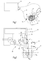
- FIG. 1 schematically illustrates an application situation in which by means of an electrosurgical instrument 10 to biological tissue 11, a treatment is performed.
- the instrument 10 is supplied to this by a device 12 with electric current.
- the voltage u provided by the device 12 and the current i supplied to the instrument 10 are preferably periodic quantities with a frequency of preferably several 100 kHz, for example 350 kHz.
- a first line 13 leads from the device 12 to the instrument 10.
- a second line 14 leads from the device 12 to a large, on the intact surface of the tissue 11, in particular the skin of the patient, mounted neutral electrode 15th
- the instrument 10 has at least one electrode 17 from which a flow of current to the biological tissue 11 originates.
- the current may flow through direct tissue contact or via a spark 18 that will flip between the electrode 17 and the biological tissue 11.
- the spark 18 can traverse a volume which contains air and / or steam and / or other liquids such as purisols, saline and / or another gas such as nitrogen, carbon dioxide or noble gas such as in particular argon.
- the existing gas or gas mixture or vapor ionizes in the region of the spark 18 and forms a plasma, wherein the spark touches the biological tissue 11 and introduces power into it.
- the biological tissue 11 may be electrically conductive Contain foreign bodies, in particular metal parts 19, in particular stents 20 (FIG. FIG. 1 ) for holding open hollow vessels 21 such as the esophagus or the like.
- the metal part 19 may also be a clip, screw, plate, wire, or other component introduced into the body of a patient.
- the spark When performing treatments of the biological tissue 11, it may happen that the spark contacts 18 metal parts 19. Such contact should not be uncontrolled. It may be desirable, for example, to selectively heat or cut metal parts, for example, to shorten stents or to heat surgical forceps, for example, to cause tissue coagulation between the tweezers. However, it may also be undesirable, for example, if a heating of metal parts 19 would lead to the damage thereof as well as damage to surrounding biological tissue. However, with poor visibility of the field of application, it is sometimes difficult for the user to recognize metal parts in a timely manner. In particular, however, it may be difficult to detect the contact of the metal parts 19 by the spark 18 fast enough.
- a metal detector 22 is provided which, as in FIG. 2 represented part of the device 12 or alternatively also part of the instrument 10 or may be formed as an intermediate module. Such an intermediate module is to be connected to the device 12 instead of the lines 13, 14, wherein the lines 13, 14 are then connected to the intermediate module.
- the metal detector 22 may include a measuring device 23 which detects the voltage u provided for the instrument 10 and the current i supplied to the instrument 10. It detects at least one characteristic value Ku of the voltage and at least one characteristic value Ki of the current.
- a characteristic value Ki of the current may be the instantaneous value i (t) the peak value i peak , the mean value i me-an , the effective value i eff or another value suitable for characterization. Such characteristics can be detected continuously or in a scanned manner. When sampling instantaneous values, it is preferable to sample at more than twice the frequency of the current (for example, more than 700 kHz).
- the instantaneous value u (t), the peak value u peak , the mean value u mean , the effective value u eff or another value suitable for characterization can likewise be detected as the characteristic value Ku for the voltage.
- the detection can be continuous or periodic.
- the voltage is preferably sampled at more than twice the frequency. In the following and above, when referring to "sensing the current” or “sensing the voltage”, this refers to the illustrated sensing of a corresponding characteristic of the current or voltage.
- the measured characteristic values Ku, Ki for the voltage and the current are transferred by the measuring device 23 to an analysis device 24.
- the analyzer is used to distinguish based on the characteristics of the current and the voltage, whether the spark 18 is in contact with the fabric 11 or with the metal part 19.
- the analysis device 24 can be used with a controller 25 of a generator 26 connected in FIG. 2 is schematically illustrated and is used to power the instrument 10 with high-frequency electrical energy.
- the generator 26 typically includes a power supply unit 27 and a power oscillator 28 connected thereto with a resonant circuit 29 and a potential-free RF decoupling coil 30.
- the controller 25 controls the operation of the generator 26, ie activates and deactivates the latter and / or the current and / or the power and / or the crest factor thereof.
- the controller 25 may communicate with control devices, not further illustrated, which are configured as switches or adjustment devices on the device 12 and / or the instrument 10 and / or as further separate switches or input devices.
- the analysis device 24 is set up to determine at least two parameters, namely a spark characteristic F rel and a resistance characteristic R.
- a spark characteristic F rel is preferably selected a characteristic which characterizes the size and / or the intensity of the spark 18.
- As a spark characteristic F rel for example, a characteristic in question, which characterizes the nonlinearity of the electrical network formed by the instrument 10, the spark 18 and the biological tissue 11. The electrical network formed in this way is simplified in FIG FIG. 2 illustrated.
- the tissue resistance R G1 is the resistance of the biological Fabric when the spark hits 18 on this.
- the tissue resistance R G2 is the typically lower tissue resistance that results from the current distribution of the metal part 19 when the spark 18 hits it. Further, the nonlinear resistor of the spark 18 belongs to the network.
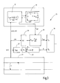
- the analyzer 24 may have an internal spare circuit 31, an internal network model 31 of that electrical network, as in FIG FIG. 3 is indicated.
- the network model 31 may be a simplified representation of the actual after FIG. 2 existing network, in which the occurring inductances, capacitances and resistances to elements R, L, C are summarized.
- a simplified network model 31a or 31b can be used FIG. 4 or FIG. 5 to get voted. The selection can make and decide the analysis device on the basis of the lag or advance of the current i to the voltage u.
- the analysis device 24 is designed to first determine the values of the elements L, R, C of the network model 31, 31a, 31b.
- the values of the elements L, R, C are determined, for example, in the course of a regression calculation or with the method of least squares, so that the currents and voltages computationally occurring in the network model 31, 31a, 31b correspond optimally to the actually detected current and in fact detected voltage are adjusted.
- the ohmic cable resistance R cable is usually less than 1 ohm, this is negligible.
- the value R of the resistance after the network model 31a, b after FIG. 4 or 5 the tissue resistance.
- the portions of the current i and the voltage u which are inconsistent with the linear network model are assigned to the nonlinear resistance F of the spark 18.
- the determination of the values of the elements L, R, C can take place at the beginning of an activation, or at intervals or continuously.
- FIG. 3 illustrates for this purpose several blocks for illustrating the processing of the measured current i (t) and the voltage u (t). These blocks may be implemented by program code or otherwise. The assignment of functions to blocks is purely exemplary and can also be taken otherwise.
- a block 32 determines the elements R, L and / or C of the network model 31 sporadically, periodically or continuously FIG. 3 . 4 or 5 .
- the network model 31 then calculates with the input of the measured voltage u (t) a current i sim (t) and its difference i f (t) to the measured current i (t) and its effective value Feff of i f (t).
- the current i sim (t) does not coincide with the effective value i eff of the measured current i (t), in particular when the spark 18 has ignited.
- the current error i f (t) is calculated as the difference of the equivalent circuit FIG. 4 or 5
- Block 32 calculates the deviation of the simulated current i sim (t) from the measured current i (t) as current error i f (t).
- i f (t) can also be calculated from the instantaneous values of the setpoint current i sim (t) and the actual current i (t).
- the current error i f (t) becomes maximum when the measured HF current i (t) deviates maximally from the calculated regression current. This deviation is the case especially in HF surgical applications with sparking, where due to the sparking to a strong distortion of the RF current i (t) comes.
- the non-linear component of the equivalent circuit for calculating the regression current is particularly high.
- the linear elements of the equivalent circuit after FIGS. 3 to 5 can not completely explain the measured HF current i (t) and lead to a regression current i sim (t) deviating from the measured HF current i (t). This correlates with a high current error i f (t), whereby the effective radio characteristic value F eff increases accordingly.
- the analysis device 24 calculates the linear values on the basis of the regression analysis of the network model 31 FIG. 3 or 31a or b according to FIG. 4 or 5.
- the ohmic component R can be used as a resistance characteristic, which mainly characterizes the resistance of the biological tissue 11, ie in the illustration according to FIG FIG. 2 attributable to tissue resistance R G1 or R G2 .
- the regression calculation for this is carried out continuously by the block 32, the regression block, in order to determine the resistance parameter R currently during the entire operation of the instrument 10.
- the tissue resistance may also be as in FIG. 3 can be determined by a separate resistance calculation block 33.
- the blocks 36, 37 first determine from the instantaneous values i (t) and u (t) the rms values of the HF voltage and of the HF current u eff and i eff , as well as the power factor cos ⁇ .
- the resistance calculation block 33 can also obtain these rms values from the measuring device 23.
- the resistance calculation block 33 forms the quotient of the rms value u eff of the rf voltage u (t) and the rms value i eff multiplied by the power factor cos ⁇ .
- a comparator 34 compares the spark characteristic F rel determined in block 35 with a spark size threshold F 0 .
- the comparator compares the resistance characteristic R with a resistance threshold R 0 .
- the process is illustrated FIG. 6 ,
- the spark characteristic F rel may be greater or less than the spark size threshold F 0 .
- the resistance characteristic R may be larger or smaller than the resistance value threshold R 0 . This results in four possible constellations. It has been found that with a suitable choice of R 0 to, for example, 300 ohms and F 0 to 0.4, for example, the contact of metal is given by the spark 18 when the resistance characteristic R is smaller than the resistance threshold R 0 and the spark characteristic F rel is greater than the spark size threshold F 0 .
- the other three constellations have other situations, for example contact application between instrument 10 and tissue 11 without sparking, activation of the electrode 17 in air without ignited sparks or spark to tissue 11 with sparking. If, by contrast, a spark ignited against a metal part is detected, a branch is made to a block 38 which symbolizes a corresponding measure.
- a measure may be the transmission of a detectable signal or an influence on the controller 25. This can, for example, reduce or increase the power or switch off the generator 26, change the crest factor or the like.
- FIG. 7 illustrates a modified embodiment of the method.
- the resistance characteristic R and the spark characteristic F rel are determined continuously. Unlike the method described above, however, they are not compared to absolute threshold values F 0 and R 0 . Rather, the time variation dR / dt of the resistance characteristic R and the temporal change dF rel / dt of the spark characteristic F rel are determined as an evaluation criterion and compared with limit values ro and fo.
- the action block 38 is in turn branched when the change dR / dt of the tissue resistance under a resistance change threshold ro and the change dF rel / dt of the spark characteristic F rel is greater than a spark size change threshold f 0 . This makes it possible to avoid false conclusions about metal contact by stochastic measured value fluctuation.
- a metal detection device in spark-forming electrosurgical instruments 10 includes a metal detector 22, which differs on the basis of supplied to the instrument 10 current i (t) (and the voltage), whether an emanating from the instrument 10 spark 18 on biological tissue 11 or a Metal part 19 hits. This is preferably done by determining that portion of the current i (t) that does not match a linear equivalent circuit 31. The elements of the linear equivalent circuit 31 are determined before or during operation in a regression calculation. From the current i (t), the spark characteristic F rel is determined as the first decision criterion. As a second decision criterion, a resistance parameter R is determined which characterizes the tissue resistance. Both parameters are compared with threshold values F 0 , Ro.
Landscapes
- Health & Medical Sciences (AREA)
- Surgery (AREA)
- Life Sciences & Earth Sciences (AREA)
- Engineering & Computer Science (AREA)
- Physics & Mathematics (AREA)
- Veterinary Medicine (AREA)
- Public Health (AREA)
- Nuclear Medicine, Radiotherapy & Molecular Imaging (AREA)
- Biomedical Technology (AREA)
- Heart & Thoracic Surgery (AREA)
- Medical Informatics (AREA)
- Molecular Biology (AREA)
- Animal Behavior & Ethology (AREA)
- General Health & Medical Sciences (AREA)
- Otolaryngology (AREA)
- Plasma & Fusion (AREA)
- General Physics & Mathematics (AREA)
- Surgical Instruments (AREA)
- Oral & Maxillofacial Surgery (AREA)
- Pathology (AREA)
- Geophysics And Detection Of Objects (AREA)
- Plasma Technology (AREA)
- Measurement And Recording Of Electrical Phenomena And Electrical Characteristics Of The Living Body (AREA)
Abstract
Description
- Die Erfindung betrifft eine Einrichtung zum Erkennen von Fremdkörpern, insbesondere metallischen Fremdkörpern im biologischen Gewebe bei Einwirkung auf dieses mittels elektrochirurgischer Instrumente, die elektrische Entladungen erzeugen.
- Elektrochirurgische Instrumente, die eine im fluidförmigen Medium stattfindende elektrische Entladung nutzen, um auf biologisches Gewebe einzuwirken, sind prinzipiell bekannt. Solche Instrumente sind beispielsweise Argon-Plasma-Koagulationsinstrumente, die einen in Argonatmosphäre brennenden Funken oder einen Plasmastrahl erzeugen, Funkenskalpelle oder dergleichen. Monopolare und bipolare Resektionsinstrumente, die in nichtleitfähiger (Purisole) oder leitfähiger (Kochsalzlösung) Flüssigkeit, die Flüssigkeit derart erhitzen, dass die Flüssigkeit verdampft und sich in diesem Dampf Funken zum Gewebe oder einer weiteren Elektrode bilden sind bekannt. Beim Umgang mit Argon-Plasma-Koagulationsinstrumenten ist besondere Vorsicht geboten, wenn im biologischen Gewebe Fremdkörper, insbesondere metallische Fremdkörper, vorhanden sind. Es kann sich dabei beispielsweise um Stents oder sonstige Metallteile handeln, die einem Patienten bereits in der Vergangenheit oder auch während des aktuellen Eingriffs eingepflanzt worden sind. Erfolgt die Funken- oder Plasmaeinwirkung auf einen Stent, eine metallische Klammer oder einem sonstigen Metallkörper im biologischen Gewebe, unbeabsichtigt, kann daraus eine Schädigung des Metallteils folgen, wodurch dieses seine Funktion verlieren kann. Auch kann das umliegende Gewebe beispielsweise aufgrund von Wärmeleitung unerwünscht geschädigt werden.
- Andererseits gibt es Fälle, in denen die Funken- oder Plasmaeinwirkung auf den metallischen Fremdkörper gewünscht ist, beispielsweise um die Kürzung eines Stents oder bestimmte chirurgische Eingriffe vorzunehmen. Solche sind beispielsweise die Koagulation eines blutenden Gefäßes mittels einer anatomischen Pinzette, die durch den Funken- oder Plasmastrahl des elektrochirurgischen Instruments gezielt erwärmt und somit zur Koagulation des Gefäßes befähigt wird.
- Weiterhin ist für die Anwendung von monopolaren und bipolaren Resektionsschlingen in der TUR bekannt, dass es bei zu geringem Abstand zwischen der Resektionsschlinge und dem Resektoskop unbeabsichtigt zur Funkenbildung auf das metallische Resektoskop kommt. Diese unerwünschte Funkenbildung führt zum Stromfluss durch das metallische Resektoskop. Da das Resektoskop wiederum mit dem biologischen Gewebe in Kontakt ist, kommt es zu unerwünschten Koagulationseffekten an dem Gewebe.
- Daraus ergibt sich die Aufgabe, ein Konzept zu schaffen, mit dem sich die Einwirkung eines funkenbildenden elektrischen Instruments auf Metall sicher von der Einwirkung des Instruments auf biologisches Gewebe unterscheiden lässt.
- Diese Aufgabe wird mit der Einrichtung nach Anspruch 1 gelöst:
- Die erfindungsgemäße Einrichtung kann zu einem elektrochirurgischen Instrument gehören oder Bestandteil desselben sein. Sie kann ebenso gut zu einem zur Speisung des Instruments vorgesehenen Generator gehören oder Bestandteil desselben sein. Alternativ kann die Einrichtung als gesonderte Baugruppe zwischen dem Generator und dem elektrochirurgischen Instrument angeordnet sein.
- Zu der Einrichtung gehört eine Messeinrichtung zur Erfassung einer von dem Generator zum Betrieb des Instruments bereitgestellten Spannung und zur Erfassung des von dem Generator zu dem Instrument gelieferten Stroms. Ist der Innenwiderstand des Generators gering oder Null und die abgegebene Spannung bekannt, kann auf die Messung derselben auch verzichtet werden; es genügt dann die Erfassung des Stroms. Die Erfassung des Stroms (und der Spannung) kann kontinuierlich oder intermittierend, beispielsweise in kurzen Zeitabständen erfolgen. Vorzugsweise erfolgt die Erfassung der Spannung und des Stroms in kurzen Zeitabständen. Liefert der Generator eine Wechselspannung zur Speisung des elektrochirurgischen Instruments, vorzugsweise eine HF-Wechselspannung, sind die Zeitabstände vorzugsweise kürzer als die halbe Periodendauer der Spannung bzw. des Stroms. Bei der Erfassung der Spannung bzw. des Stroms wird mindestens ein geeigneter Kennwert der Spannung sowie des Stroms erfasst. Ein solcher Kennwert kann der Augenblickswert, der Spitzenwert, der Mittelwert, der Effektivwert oder ein anderer zur Charakterisierung geeigneter Wert sein.
- Der zur Einrichtung gehörige Metalldetektor ist dazu eingerichtet, anhand des Stroms und anhand der Spannung, d.h. letztlich anhand eines oder mehrerer Kennwerte für den Strom sowie eines oder mehrere Kennwerte für die Spannung, zu entscheiden, ob ein von dem Instrument ausgehender Funken auf biologisches Gewebe oder ein Metallteil trifft.
- Mit dieser Einrichtung kann der Anwender auch bei schlechten Sichtverhältnissen zuverlässig und frühzeitig erkennen, wenn mit einem Funken oder Plasma auf ein Metallteil eingewirkt wird. Es ist möglich, den Metalldetektor mit einer Signalisierungseinrichtung zu verbinden, um dem Anwender ein geeignetes, zum Beispiel haptisches, optisches oder akustisches Signal bereitzustellen, damit dieser eine Metallberührung durch das Plasma oder den Funken erkennt. Es ist außerdem möglich, ein von dem Metalldetektor erzeugtes Signal zum Abschalten des Generators oder zu seiner anderweitigen Steuerung zu nutzen. Zum Beispiel kann die Leistung des Generators bei Metallerkennung reduziert werden, um unerwünschte biologische Wirkungen zu vermeiden. Ist hingegen eine Einwirkung auf das Metall gewünscht, kann das Signal dazu genutzt werden, den Generator nicht abzuschalten sondern in seiner Leistung zu erhöhen, wenn eine Berührung von Metall durch den Funken oder das Plasma erkannt wird, um zum Beispiel das Trennen von Metall mittels Funkens oder Plasmas zu unterstützen.
- Der Metalldetektor kann eine Analyseeinrichtung enthalten, die eine Widerstandskenngröße und eine Funkenkenngröße ermittelt. Die Widerstandskenngröße ist ein vom Gewebewiderstand abhängiger Wert. Die Funkenkenngröße ist vorzugsweise ein von der Funkengröße abhängiger Wert. Beide Kenngrößen, die Widerstandsgröße und die Funkenkenngröße, können mit entsprechenden Schwellwerten verglichen werden, um aus diesem Vergleich ein aussagekräftiges Signal zu generieren. Vorzugsweise wird eine Metallberührung durch das Plasma oder den Funken dann signalisiert, wenn die elektrische Widerstandskenngröße, der Widerstandskennwert den Widerstandsschwellwert unterschreitet und die Funkenkenngröße, der Funkenkennwert den Funkengrößenschwellwert überschreitet. Alle anderen Kombinationen können anderen Situationen zugeordnet werden:
- - Der Widerstandskennwert unterschreitet den Widerstandsschwellwert und die Funkenkenngröße ist geringer als der Funkengrößenschwellwert. Es liegt eine direkte Berührung zwischen der Elektrode des Instruments und dem Gewebe vor.
- - Falls die Widerstandskenngröße größer als der Widerstandsschwellwert die Funkengröße jedoch kleiner als der Funkengrößenschwellwert ist, besteht kein Funke oder der Funke schlägt in die Luft.
- - Die Widerstandskenngröße ist größer als der Widerstandsschwellwert und zugleich ist die Funkenkenngröße größer als der Funkengrößenschwellwert ist, liegt eine Einwirkung des Funkens oder Plasmas auf das Gewebe ohne Metallberührung vor.
- Zur Berechnung oder sonstigen Ermittlung der Widerstandskenngröße und der Funkenkenngröße können alle geeigneten Verfahren angewendet werden. Beispielsweise kann die Widerstandskenngröße als der lineare Anteil des elektrischen Widerstands festgelegt sein, der sich als Quotient eines Kennwerts für den gemessenen Strom und eines Kennwertes der gemessenen Spannung ergibt. Insbesondere kann der Quotient aus den Effektivwerten von Strom und Spannung gebildet und dann mit dem Leistungsfaktor multipliziert werden, um die Widerstandskenngröße zu bilden. In dieser Widerstandskenngröße ist nicht nur der Gewebewidersand enthalten. Vielmehr kommen weitere Anteil, beispielsweise der Leitungswiderstand der Zuleitung des Instruments und gegebenenfalls auch lineare Widerstandsanteile aus dem Funken hinzu. Jedoch ist die so ermittelte Widerstandskenngröße ein gutes Maß für den Gewebewiderstand.
- Zur Ermittlung der Funkenkenngröße kann der nichtlineare Anteil des Stroms bestimmt werden, der maßgeblich auf den von dem Funken gebildeten nichtlinearen Widerstand zurückgeht. Dazu kann die Analyseeinrichtung darauf eingerichtet sein, anhand eines linearen Ersatzschaltbilds und der gemessenen Spannung (bzw. des entsprechenden Kennwerts der Spannung) den zugehörigen Strom isim(t) zu berechnen. Die Differenz if(t) zwischen dem berechneten Strom isim(t) und dem gemessenen Strom i(t) kennzeichnet den von der Nichtlinearität des Funkens hervorgerufenen Strom. Das Verhältnis aus dem Effektivwert Feff dieser Differenz if(t) und dem Effektivwert ieff des gemessenen Stroms i(t) kann als Funkenkenngröße Frel genutzt werden.
- Anstelle des Vergleichs der Widerstandskenngröße mit dem Widerstandsschwellwert und des Vergleichs der Funkenkenngröße mit dem Funkengrößenschwellwert ist es auch möglich, die Widerstandskenngröße und die Funkenkenngröße auf schnelle zeitliche Veränderungen hin zu untersuchen. Übersteigt die Steilheit des Anstiegs der Funkenkenngröße dFrel/dt sowie des Anstiegs der Widerstandskenngröße dR/dt jeweils einen bestimmten Grenzwert f0, r0, kann wiederum auf Metallberührung geschlossen werden.
- Einzelheiten von Ausführungsformen der Erfindung ergeben sich aus der Zeichnung, Ansprüchen sowie insbesondere der Beschreibung. Es zeigen:
-
Figur 1 ein von einem Generator gespeistes funkenbildendes, elektrochirurgisches Instrument bei der Einwirkung auf biologisches Gewebe, in schematisierter Veranschaulichung. -
Figur 2 Komponenten des Generators des Instruments und des biologischen Gewebes als Schaltbild. -
Figur 3 ein Blockschaltbild der Einrichtung zur Metallerkennung. -
Figur 4 und 5 von der Einrichtung nachFigur 3 genutzte Ersatzschaltungen. -
Figur 6 ein Ablaufschema für die Metallerkennung auf Basis von Widerstandsschwellwert und Funkengrößenschwellwert und -
Figur 7 ein Ablaufschema zur Metallerkennung auf Basis der zeitlichen Veränderung der Widerstandskenngröße und der Funkenkenngröße. - In
Figur 1 ist schematisch eine Anwendungssituation veranschaulicht, bei der mittels eines elektrochirurgischen Instruments 10 an biologischem Gewebe 11 eine Behandlung durchgeführt wird. Das Instrument 10 wird dazu von einem Gerät 12 mit elektrischem Strom versorgt. Die von dem Gerät 12 bereitgestellte Spannung u sowie der zu dem Instrument 10 gelieferte Strom i sind vorzugsweise periodische Größen mit einer Frequenz von vorzugsweise mehreren 100 kHz, zum Beispiel 350 kHz. Obwohl die vorliegende Erfindung darauf nicht beschränkt ist, eignet sie sich insbesondere für monopolare Anwendungen. Entsprechend führt eine erste Leitung 13 von dem Gerät 12 zu dem Instrument 10. Eine zweite Leitung 14 führt von dem Gerät 12 zu einer großflächigen, an der unversehrten Oberfläche des Gewebes 11, insbesondere der Haut des Patienten, angebrachten Neutralelektrode 15. - Das Instrument 10 weist mindestens eine Elektrode 17 auf, von der ein Stromfluss zu dem biologischen Gewebe 11 ausgeht. Je nach aktueller Situation kann der Strom durch direkten Gewebekontakt oder über einen Funken 18 fließen, der zwischen der Elektrode 17 und dem biologischen Gewebe 11 überschlägt. Der Funken 18 kann dabei je nach Anwendungsfall ein Volumen durchqueren, das Luft und/oder Wasserdampf und/oder Dampf anderer Flüssigkeiten wie Purisole, Kochsalzlösung und/oder ein sonstiges Gas wie Stickstoff, Kohlendioxid oder Edelgas wie insbesondere Argon enthält. Das vorhandene Gas oder Gasgemisch oder Dampf ionisiert im Bereich des Funkens 18 und bildet ein Plasma, wobei der Funke das biologische Gewebe 11 berührt und Strom in dieses einleitet.
- Das biologische Gewebe 11 kann elektrisch leitende Fremdkörper, insbesondere Metallteile 19 enthalten, wie insbesondere Stents 20 (
Figur 1 ) zum Offenhalten von Hohlgefäßen 21 wie dem Ösophagus oder dergleichen. Das Metallteil 19 kann außerdem eine Klammer, eine Schraube, Platte, ein Draht oder ein sonstiges in den Körper eines Patienten eingebrachtes Bauteil sein. - Bei der Vornahme von Behandlungen des biologischen Gewebes 11 kann es vorkommen, dass der Funke 18 Metallteile 19 berührt. Eine solche Berührung soll keinesfalls unkontrolliert erfolgen. Sie kann erwünscht sein, beispielsweise um Metallteile gezielt zu erwärmen oder zu durchtrennen, beispielsweise um Stents zu kürzen oder Operationspinzetten zu erwärmen, beispielsweise um eine Gewebekoagulation zwischen den Branchen der Pinzette hervorzurufen. Sie kann jedoch auch unerwünscht sein, beispielsweise wenn eine Erwärmung von Metallteilen 19 zur Schädigung derselben sowie zur Schädigung umliegenden biologischen Gewebes führen würde. Bei schlechter Sicht auf das Anwendungsgebiet, ist es für den Anwender jedoch manchmal schwierig, Metallteile rechtzeitig zu erkennen. Insbesondere kann es jedoch schwierig sein, die Berührung der Metallteile 19 durch den Funken 18 schnell genug zu erkennen.
- Zur Erkennung von Metallberührung durch den Funken 18 ist ein Metalldetektor 22 vorgesehen, der, wie in
Figur 2 dargestellt, Teil des Geräts 12 oder alternativ auch Teil des Instruments 10 oder als Zwischenmodul ausgebildet sein kann. Ein solches Zwischenmodul ist anstelle der Leitungen 13, 14 an das Gerät 12 anzuschließen, wobei die Leitungen 13, 14 dann an das Zwischenmodul angeschlossen werden. - Zu dem Metalldetektor 22 kann eine Messeinrichtung 23 gehören, die die für das Instrument 10 bereitgestellte Spannung u sowie dem zu dem Instrument 10 gelieferten Strom i erfasst. Sie erfasst dabei mindestens einen Kennwert Ku der Spannung sowie mindestens einen Kennwert Ki des Stroms. Ein solcher Kennwert Ki des Stroms kann der Augenblickswert i (t) der Spitzenwert ipeak, der Mittelwert ime-an, der Effektivwert ieff oder ein anderer zur Charakterisierung geeigneter Wert sein. Solche Kennwerte können kontinuierlich oder in abgetasteter Weise erfasst werden. Beim Abtasten von Augenblickswerten wird vorzugsweise mit mehr als doppelter Frequenz des Stroms abgetastet (zum Beispiel mit mehr als 700 kHz). Als Kennwert Ku für die Spannung kann gleichfalls der Augenblickswert u(t), der Spitzenwert upeak, der Mittelwert umean, der Effektivwert ueff oder ein anderer zur Charakterisierung geeigneter Wert erfasst werden. Die Erfassung kann kontinuierlich oder periodisch erfolgen. Bei Abtastung des Augenblickswerts wird vorzugsweise mit mehr als der doppelten Frequenz der Spannung abgetastet. Wenn im Nachfolgenden und im Vorstehenden von der "Erfassung des Stroms" oder "Erfassung der Spannung" gesprochen wird, bezieht sich dies auf die erläuterte Erfassung eines entsprechenden Kennwerts des Stroms oder der Spannung.
- Die gemessenen Kennwerte Ku, Ki für die Spannung und den Strom werden von der Messeinrichtung 23 an eine Analyseeinrichtung 24 übergeben. Die Analyseeinrichtung dient dazu, anhand der Kenngrößen für den Strom und die Spannung zu unterscheiden, ob der Funken 18 mit dem Gewebe 11 oder mit dem Metallteil 19 in Berührung steht.
- Die Analyseeinrichtung 24 kann im Weiteren mit einer Steuerung 25 eines Generators 26 verbunden sein, der in
Figur 2 schematisch veranschaulicht ist und zur Speisung des Instruments 10 mit hochfrequenter elektrischer Energie dient. Der Generator 26 umfasst typischerweise neben der Steuereinrichtung 25 ein Netzteil 27 und einen daran angeschlossenen Leistungsoszillator 28 mit einem Schwingkreis 29 und einer potentialfreien HF-Auskoppelspule 30. Die Steuerung 25 kontrolliert den Betrieb des Generators 26, d.h. sie aktiviert und deaktiviert diesen, gibt die Spannung und/oder den Strom und/oder die Leistung und/oder den Crestfaktor desselben vor. Die Steuerung 25 kann mit nicht weiter veranschaulichten Bedienorganen kommunizieren, die als Schalter oder Einstellvorrichtungen an dem Gerät 12 und/oder dem Instrument 10 und/oder als weitere gesonderte Schalter oder Eingabeeinrichtungen ausgebildet sind. - Um anhand des erfassten Stroms und der erfassten Spannung zu erkennen, ob der Funke 18 das Gewebe 11 oder das Metallteil 19 berührt, ist die Analyseeinrichtung 24 dazu eingerichtet, mindestens zwei Kenngrößen zu bestimmen, nämlich eine Funkenkenngröße Frel und eine Widerstandskenngröße R. Als Funkenkenngröße Frel wird vorzugsweise eine Kenngröße ausgewählt, die die Größe und/oder die Intensität des Funkens 18 kennzeichnet. Als Funkenkenngröße Frel kommt beispielsweise eine Kenngröße in Frage, die die Nichtlinearität des von dem Instrument 10, dem Funken 18 und dem biologischen Gewebe 11 gebildeten elektrischen Netzwerks kennzeichnet. Das so gebildete elektrische Netzwerk ist in vereinfachter Form in
Figur 2 veranschaulicht. Zu ihm gehören der ohmsche Widerstand RKabel der Leitungen 13, 14, die Induktivität LKabel, die zwischen den Leitungen 13, 14 zu messende Kapazität C sowie der Gewebewiderstand RG1 oder RG2. Der Gewebewiderstand RG1 ist der Widerstand des biologischen Gewebes, wenn der Funken 18 auf dieses trifft. Der Gewebewiderstand RG2 ist der typischerweise geringere Gewebewiderstand, der sich durch die Stromverteilung des Metallteils 19 ergibt, wenn der Funken 18 auf dieses trifft. Weiter gehört zu dem Netzwerk der nichtlineare Widerstand des Funkens 18. - Die Analyseeinrichtung 24 kann über eine interne Ersatzschaltung 31, ein internes Netzwerkmodell 31 dieses elektrischen Netzwerks verfügen, wie in
Figur 3 angedeutet ist. Das Netzwerkmodell 31 kann eine vereinfachte Repräsentation des tatsächlich nachFigur 2 vorhandenen Netzwerks sein, bei dem die auftretenden Induktivitäten, Kapazitäten und Widerstände zu Elementen R, L, C zusammengefasst sind. Je nachdem, ob sich das Netzwerk aktuell vorwiegend induktiv oder vorwiegend kapazitiv verhält, kann anstelle des Netzmodells 31 ein vereinfachtes Netzmodell 31a oder ein 31b gemäßFigur 4 oder Figur 5 gewählt werden. Die Auswahl kann die Analyseeinrichtung anhand der Nach- oder Voreilung des Stroms i zur Spannung u treffen und entscheiden. - Die Analyseeinrichtung 24 ist dazu ausgelegt, zunächst die Werte der Elemente L, R, C des Netzwerkmodells 31, 31a, 31b zu bestimmen. Dazu werden die Werte der Elemente L, R, C zum Beispiel im Rahmen einer Regressionsrechnung oder mit der Methode des kleinsten Fehlerquadrats so festgelegt, dass die im Netzwerkmodell 31, 31a, 31b rechnerisch auftretenden Ströme und Spannungen bestmöglich an den tatsächlich erfassten Strom und die tatsächlich erfasste Spannung angepasst sind. Nachdem der ohmsche Leitungswiderstand RKabel meist weniger als 1 Ohm beträgt, ist dieser vernachlässigbar. Damit entspricht der Wert R des Widerstands nach dem Netzwerkmodell 31a,b nach
Figur 4 oder 5 dem Gewebewiderstand. Die mit dem linearen Netzmodell nicht in Einklang bringenden Anteile des Stroms i und der Spannung u werden dem nichtlinearen Widerstand F des Funkens 18 zugeordnet. Die Bestimmung der Werte der Elemente L, R, C kann zu Beginn einer Aktivierung, oder in Zeitabständen oder kontinuierlich erfolgen. - Aus dem realen Strom i(t) und dem durch das lineare Netzwerk vorgegebenen Strom iSim(t) lässt sich wie in
Figur 3 angedeutet die Funkenkenngröße Frel bestimmen.Figur 3 veranschaulicht dazu mehrere Blöcke zur Veranschaulichung der Verarbeitung des gemessenen Stroms i(t) und der Spannung u(t). Diese Blöcke können durch Programmcode oder anderweitig realisiert sein. Die Zuordnung von Funktionen zu Blöcken ist rein beispielhaft und kann auch anderweitig getroffen sein. - Ein Block 32 bestimmt sporadisch, periodisch oder kontinuierlich die Elemente R, L und/oder C des Netzwerkmodells 31 nach
Figur 3 ,4 oder 5 . Das Netzwerkmodell 31 berechnet dann mit dem Input der gemessenen Spannung u(t) einen Strom isim(t) sowie dessen Differenz if(t) zum gemessenen Strom i(t) und dessen Effektivwert Feff von if(t). Der Strom isim(t) stimmt, insbesondere wenn der Funke 18 gezündet hat, nicht mit dem Effektivwert ieff des gemessenen Stroms i(t) überein. - Der Stromfehler if(t) berechnet sich als Differenz des aus dem Ersatzschaltbild nach
Figur 4 oder 5 für die HF-chirurgische Anwendung berechneten Sollstroms isim(t) und des während der HF-Applikation gemessenen HF-Stroms i (t) :
- Block 32 errechnet die Abweichung des simulierten Stroms isim(t) vom gemessenen Strom i (t) als Stromfehler if(t). Alternativ kann auch if(t) anhand der Augenblickswerte des Sollstroms isim(t) und des tatsächlichen Stroms i(t) errechnet werden. Feff ist der Effektivwert des Stromfehlers if(t):

und wird in Block 32 berechnet. - Der Stromfehler if(t) wird maximal, wenn der gemessene HF-Strom i(t) von dem berechneten Regressionsstrom maximal abweicht. Diese Abweichung ist vor allem bei HFchirurgischen Anwendungen mit Funkenbildung der Fall, bei dem es aufgrund der Funkenbildung zu einer starken Verzerrung des HF-Stroms i(t) kommt. Im Fall der Funkenbildung und der damit einhergehenden Verzerrung des Stroms ist der nichtlineare Anteil des Ersatzschaltbilds zur Berechnung des Regressionsstroms besonders hoch. Die linearen Elemente des Ersatzschaltbilds nach
Figur 3 bis 5 können den gemessenen HF-Strom i(t) nicht vollständig erklären und führen zu einem von dem gemessenen HF-Strom i(t) abweichenden Regressionsstrom isim(t). Dies korreliert mit einem hohen Stromfehler if(t), wodurch der effektive Funkenkennwert Feff entsprechend ansteigt. Durch Verhältnisbildung mit dem gemessenen effektiven HF-Strom ieff wird in Block 35 ein relatives Maß für die Funkenbildung erhalten. - Die Analyseeinrichtung 24 berechnet, wie oben erläutert, anhand der Regressionsanalyse die linearen Werte des Netzwerkmodels 31 nach
Figur 3 bzw. 31a oder b nach Figur 4 oder 5. Der ohmsche Anteil R kann als Widerstandskenngröße genutzt werden, die hauptsächlich den Widerstand des biologischen Gewebes 11 kennzeichnet, d.h. in der Darstellung nachFigur 2 dem Gewebewiderständen RG1 oder RG2 zuzuordnen ist. Die Regressionsrechnung dazu wird von dem Block 32, dem Regressionsblock fortwährend durchgeführt, um während des gesamten Betriebs des Instruments 10 aktuell die Widerstandskenngröße R zu bestimmen. - Alternativ kann der Gewebewiderstand auch, wie in
Figur 3 veranschaulicht, durch einen gesonderten Widerstandsrechenblock 33 bestimmt werden. Dazu bestimmen die Blöcke 36, 37 zunächst aus den Augenblickswerten i(t) und u(t) die Effektivwerte der HF-Spannung und des HF-Stroms ueff und ieff, sowie den Leistungsfaktor cosΦ. (Alternativ kann der Widerstandsrechenblock 33 diese Effektivwerte auch von der Messeinrichtung 23 erhalten.) Als Widerstandskenngröße bildet der Widerstandsrechenblock 33 den Quotienten des Effektivwerts ueff der HF-Spannung u(t) und des Effektivwerts ieff multipliziert mit dem Leistungsfaktor cosΦ. - Ein Komparator 34 vergleicht die in Block 35 ermittelte Funkenkenngröße Frel mit einem Funkengrößenschwellwert F0. Außerdem vergleicht der Komaparator die Widerstandskenngröße R mit einem Widerstandsschwellwert R0. Den Ablauf veranschaulicht
Figur 6 . Die Funkenkenngröße Frel kann größer oder kleiner sein als der Funkengrößenschwellwert F0. Ebenso kann die Widerstandskenngröße R größer oder kleiner sein als der Widerstandsgrößenschwellwert R0. Daraus ergeben sich vier mögliche Konstellationen. Es hat sich gezeigt, dass bei geeigneter Wahl von R0 zu beispielsweise 300 Ohm und F0 zu beispielsweise 0,4 die Berührung von Metall durch den Funken 18 dann gegeben ist, wenn die Widerstandskenngröße R kleiner als der Widerstandsschwellwert R0 und die Funkenkenngröße Frel größer als der Funkengrößenschwellwert F0 ist. Bei den anderen drei Konstellationen liegen andere Situationen vor, zum Beispiel Kontaktanwendung zwischen Instrument 10 und Gewebe 11 ohne Funkenbildung, Aktivierung der Elektrode 17 in Luft ohne gezündetem Funken oder Funke zum Gewebe 11 mit Funkenbildung. Wird hingegen ein gegen ein Metallteil gezündeter Funke erfasst, wird zu einem Block 38 verzweigt, der eine entsprechende Maßnahme symbolisiert. Eine solche Maßnahme kann die Aussendung eines wahrnehmbaren Signals oder eine Beeinflussung der Steuerung 25 sein. Diese kann beispielsweise die Leistung reduzieren oder erhöhen oder den Generator 26 abschalten, den Crestfaktor ändern oder dergleichen. -
Figur 7 veranschaulicht eine abgewandelte Ausführungsform des Verfahrens. Es werden wiederum laufend, wie vorstehend beschrieben, die Widerstandskenngröße R und die Funkenkenngröße Frel bestimmt. Anders als im vorstehend beschriebenen Verfahren werden diese jedoch nicht mit absolutem Schwellwerten F0 und R0 verglichen. Vielmehr wird als Auswertekriterium die zeitliche Veränderung dR/dt der Widerstandskenngröße R und die zeitliche Veränderung dFrel/dt der Funkenkenngröße Frel ermittelt und mit Grenzwerten ro und fo verglichen. Zu dem Maßnahmenblock 38 wird wiederum dann verzweigt, wenn die Veränderung dR/dt des Gewebewiderstands unter einem Widerstandsänderungsschwellwert ro und die Veränderung dFrel/dt der Funkenkenngröße Frel größer als ein Funkengrößenänderungsschwellwert f0 ist. Damit gelingt es, falsche Rückschlüsse auf Metallberührung durch stochastische Messwertschwankung zu vermeiden. - Eine erfindungsgemäße Einrichtung zur Metallerkennung bei funkenbildenden elektrochirurgischen Instrumenten 10 enthält einen Metalldetektor 22, der anhand des zu dem Instrument 10 gelieferten Stroms i(t) (sowie der Spannung) unterscheidet, ob ein von dem Instrument 10 ausgehender Funke 18 auf biologisches Gewebe 11 oder ein Metallteil 19 trifft. Vorzugsweise erfolgt dies durch Bestimmung desjenigen Anteils des Stroms i(t), der nicht zu einer linearen Ersatzschaltung 31 passt. Die Elemente der linearen Ersatzschaltung 31 werden zuvor oder während des Betriebs in einer Regressionsrechnung bestimmt. Aus dem Strom i(t) wird als erstes Entscheidungskriterium die Funkenkenngröße Frel bestimmt. Als zweites Entscheidungskriterium wird eine Widerstandskenngröße R bestimmt, die den Gewebewiderstand kennzeichnet. Beide Kenngrößen werden mit Schwellwerten F0, Ro verglichen. Unterschreitet der Gewebewiderstand R den Widerstandsschwellwert R0 und überschreitet die Funkenkenngröße Frel den Funkengrößenschwellwert F0, wird ein Signal erzeugt, das die Aktivierung des Funkens 18 gegen ein Metallteil 19 kennzeichnet.
Bezugszeichen: 10 Instrument 11 biologisches Gewebe 12 Gerät 13, 14 Leitungen 15 Neutralelektrode u für das Instrument 10 bereitgestellte Spannung i zu dem Instrument 10 gelieferter Strom 16 17 Elektrode 18 Funken 19 Metallteil 20 Stent 21 Hohlgefäß 22 Metalldetektor 23 Messeinrichtung Ki Kennwert für den Strom i i (t) Augenblickswert des gemessenen Stroms imean Mittelwert des Stroms ieff Effektivwert des Stroms ipeak Spitzenwert des Stroms if(t) Differenz zwischen dem berechneten Strom und dem gemessenen Strom Ku Kennwert für die Spannung u (t) Augenblickswert der gemessenen Spannung umean Mittelwert der Spannung ueff Effektivwert der Spannung upeak Spitzenwert der Spannung uf(t) Differenz zwischen der berechneten Spannung und der gemessenen Spannung 24 Analyseeinrichtung 25 Steuerung 26 Generator 27 Netzteil 28 Leistungsoszillator 29 Schwingkreis 30 HF-Auskoppelspule Frel Funkenkenngröße (Verhältnis zwischen Feff und ieff(t)) R Widerstandskenngröße RKabel Ohmscher Leitungswiderstand LKabel Kabelinduktivität C Kapazität RG, RG1, RG2 Gewebewiderstand 31, 31a, 31b Ersatzschaltung, Netzwerkmodell R, L, C Elemente des Ersatzschaltbildes F Funkenwiderstand isim (t) mit dem Netzwerkmodell errechneter errechneter Strom T Periodendauer Feff Effektivwert des Stromfehlers ieff Effektivstrom 32 Regressionsblock 33 Widerstandsrechenblock F0 Funkengrößenschwellwert R0 Widerstandsschwellwert 34 Komperatorblock 35 - 38 Blöcke fo Funkengrößenänderungsschwellwert ro Widerstandsänderungsschwellwert cos Φ Leistungsfaktor
Claims (10)
- Einrichtung zur Metallerkennung bei der Einwirkung auf biologisches Gewebe (11) mittels eines funkenbildenden elektrochirurgischen Instruments (10),
mit einer Messeinrichtung (23) zur Erfassung einer von einem Generator (26) zum Betrieb des Instruments (10) bereitgestellten Spannung (u) und zur Erfassung des von dem Generator (26) zu dem Instrument (10) gelieferten Stroms (i),
mit einem Metalldetektor (22), der dazu eingerichtet ist, anhand des Stroms (i) und der Spannung (u) zu unterscheiden, ob ein von dem Instrument (10) ausgehender Funke (18) auf biologisches Gewebe (11) oder ein Metallteil (19) trifft. - Einrichtung nach Anspruch 1, dadurch gekennzeichnet, dass der Metalldetektor (22) aufweist:eine Analyseeinrichtung (24) zur Ermittlung einer vom Gewebewiderstand (RG) abhängigen Widerstandskenngröße (R) und einer von der Funkengröße abhängigen Funkenkenngröße (Frel), undeinen Komparator (34) zum Vergleich der Widerstandskenngröße (R) mit einem Widerstandsschwellwert (Ro) und der Funkenkenngröße (Frel) mit einem Funkengrößenschwellwert (Fo), wobei der Komparator (34) darauf eingerichtet ist, eine Berührung von Metall durch einen von dem Instrument (10) ausgehenden Funken (18) anzuzeigen, wenn:- der Widerstandskenngröße (R) den Widerstandsschwellwert (R0) unterschreitet und- die Funkenkenngröße (Frel) den Funkengrößenschwellwert (F0) überschreitet.
- Einrichtung nach einem der vorstehenden Ansprüche, dadurch gekennzeichnet, dass der Generator (26) ein HF-Generator ist.
- Einrichtung nach einem der vorstehenden Ansprüche, dadurch gekennzeichnet, dass die Messeinrichtung (23) darauf eingerichtet ist, den mindestens einen Kennwert (Ki, Ku) von Strom (i) und Spannung (u) fortlaufend zu bestimmen.
- Einrichtung nach Anspruch 4, dadurch gekennzeichnet, dass der Kennwert (Ki, Ku) von Strom (i) und Spannung (u) der Augenblickswert (i(t), u(t)), der Spitzenwert (ipeak, upeak), Mittelwert (imean, umean), der Effektivwert (ieff, ueff) oder ein anderer zur Charakterisierung geeigneter Wert ist.
- Einrichtung nach einem der vorstehenden Ansprüche, dadurch gekennzeichnet, dass die Messeinrichtung (23) darauf eingerichtet ist, den von Strom (i) und Spannung (u) festgelegten Leistungsfaktor (cos Φ) zu bestimmen.
- Einrichtung nach Anspruch 2, dadurch gekennzeichnet, dass die Analyseeinrichtung (24) darauf eingerichtet ist, die Funkenkenngröße (Frel) anhand des nichtlinearen Anteil des Stroms (i) zu bestimmen.
- Einrichtung nach Anspruch 7, dadurch gekennzeichnet, dass die Analyseeinrichtung (24) darauf eingerichtet ist, einen Schätzwert für den nichtlinearen Anteil des Stroms (i) zu bestimmen.
- Einrichtung nach Anspruch 8, dadurch gekennzeichnet, dass die Analyseeinrichtung (24) darauf eingerichtet ist, den Schätzwert für den nichtlinearen Anteil des Stroms (i) anhand der Abweichung des gemessenen Strom (i) von einem anhand einer linearen Ersatzschaltung (31) errechneten Stroms (isim) zu bestimmen.
- Einrichtung nach Anspruch 9, dadurch gekennzeichnet, dass die Analyseeinrichtung (24) darauf eingerichtet ist, die Werte der Elemente der linearen Ersatzschaltung (31) aus dem gemessenen Strom (i) und der gemessenen Spannung (u) zu bestimmen.
Priority Applications (7)
| Application Number | Priority Date | Filing Date | Title |
|---|---|---|---|
| EP14190155.3A EP3011923B1 (de) | 2014-10-23 | 2014-10-23 | Einrichtung zur Metallerkennung bei der Einwirkung auf biologisches Gewebe mittels eines funkenbildenden elektrochirurgischen Instruments |
| PL14190155T PL3011923T3 (pl) | 2014-10-23 | 2014-10-23 | Urządzenie do wykrywania metalu podczas oddziaływania na tkankę biologiczną za pomocą wytwarzającego iskrę instrumentu elektrochirurgicznego |
| BR102015021518-5A BR102015021518B1 (pt) | 2014-10-23 | 2015-09-03 | Dispositivo para detectar metal |
| KR1020150134042A KR101705463B1 (ko) | 2014-10-23 | 2015-09-22 | 스파킹 전기 수술 기구에 의해 생체 조직이 처치를 받을 때 금속을 검출하기 위한 디바이스 |
| US14/876,998 US10166063B2 (en) | 2014-10-23 | 2015-10-07 | Device for detecting metal when biological tissue is acted on by means of a sparking electrosurgical instrument |
| JP2015199481A JP6152153B2 (ja) | 2014-10-23 | 2015-10-07 | 生体組織がスパーク発生電気手術器具による作用を受けるときの金属検知装置 |
| CN201510650614.9A CN105534594B (zh) | 2014-10-23 | 2015-10-09 | 在点火式电外科器械作用于生物组织时检测金属的装置 |
Applications Claiming Priority (1)
| Application Number | Priority Date | Filing Date | Title |
|---|---|---|---|
| EP14190155.3A EP3011923B1 (de) | 2014-10-23 | 2014-10-23 | Einrichtung zur Metallerkennung bei der Einwirkung auf biologisches Gewebe mittels eines funkenbildenden elektrochirurgischen Instruments |
Publications (2)
| Publication Number | Publication Date |
|---|---|
| EP3011923A1 true EP3011923A1 (de) | 2016-04-27 |
| EP3011923B1 EP3011923B1 (de) | 2021-12-01 |
Family
ID=51786875
Family Applications (1)
| Application Number | Title | Priority Date | Filing Date |
|---|---|---|---|
| EP14190155.3A Active EP3011923B1 (de) | 2014-10-23 | 2014-10-23 | Einrichtung zur Metallerkennung bei der Einwirkung auf biologisches Gewebe mittels eines funkenbildenden elektrochirurgischen Instruments |
Country Status (7)
| Country | Link |
|---|---|
| US (1) | US10166063B2 (de) |
| EP (1) | EP3011923B1 (de) |
| JP (1) | JP6152153B2 (de) |
| KR (1) | KR101705463B1 (de) |
| CN (1) | CN105534594B (de) |
| BR (1) | BR102015021518B1 (de) |
| PL (1) | PL3011923T3 (de) |
Families Citing this family (5)
| Publication number | Priority date | Publication date | Assignee | Title |
|---|---|---|---|---|
| CN107582175B (zh) * | 2017-08-24 | 2024-06-11 | 广州市番禺区中医院 | 椎弓根螺钉置入探测仪 |
| US11045247B2 (en) * | 2018-02-20 | 2021-06-29 | Covidien Lp | Systems and methods for controlling arcing |
| CN113768614A (zh) * | 2021-09-16 | 2021-12-10 | 奥克兰高分子医用材料(天津)有限公司 | 一种高频回路电极垫 |
| DE102023115741A1 (de) * | 2023-06-14 | 2024-12-19 | Olympus Winter & Ibe Gmbh | Verfahren zur Steuerung eines elektrochirurgischen Instruments zur Erzeugung einesSchneidplasmas und entsprechender elektrochirurgischer Generator |
| CN121081091A (zh) * | 2024-06-07 | 2025-12-09 | 奥林匹斯冬季和Ibe有限公司 | 用于控制电外科器械的方法和电外科发生器 |
Citations (4)
| Publication number | Priority date | Publication date | Assignee | Title |
|---|---|---|---|---|
| WO1997045157A1 (en) * | 1996-05-28 | 1997-12-04 | Advanced Coronary Intervention | Medical catheters for ablation and detection |
| DE102004010769A1 (de) * | 2004-03-05 | 2005-09-22 | Klett, Johannes | Hochfrequenz-Chirurgiegerät zum Schneiden und Koagulieren biologischer Gewebe |
| EP1849425A1 (de) * | 2006-04-24 | 2007-10-31 | Covidien AG | Lichtbogenbasiertes adaptives Steuersystem für ein elektrochirurgisches Gerät |
| US20120215213A1 (en) * | 2006-09-29 | 2012-08-23 | Baylis Medical Company | Monitoring and controlling energy delivery of an electrosurgical device |
Family Cites Families (11)
| Publication number | Priority date | Publication date | Assignee | Title |
|---|---|---|---|---|
| US5558671A (en) | 1993-07-22 | 1996-09-24 | Yates; David C. | Impedance feedback monitor for electrosurgical instrument |
| US6235020B1 (en) | 1993-05-10 | 2001-05-22 | Arthrocare Corporation | Power supply and methods for fluid delivery in electrosurgery |
| NZ299133A (en) * | 1995-12-11 | 1997-09-22 | Megadyne Med Prod Inc | Electrocautery instrument; details relating to an insulation covering overlaid by a conducting layer, the layers being on a metallic shaft component of the instrument |
| EP1024769B1 (de) | 1997-10-23 | 2009-02-25 | Arthrocare Corporation | Energiezufuhr für elektrochirurgie in leitenden fluiden |
| DE102004056636B4 (de) * | 2004-11-23 | 2008-11-13 | Bowa-Electronic Gmbh | Hochfrequenzchirurgie-Gerät und Verfahren zu dessen Betrieb |
| JP2006289061A (ja) | 2006-02-20 | 2006-10-26 | Olympus Corp | 電気外科手術装置 |
| AU2008279121B2 (en) | 2007-07-24 | 2013-09-19 | Boston Scientific Scimed, Inc. | System and method for controlling power based on impedance detection, such as controlling power to tissue treatment devices |
| DE102008038314A1 (de) * | 2008-06-30 | 2010-01-07 | Erbe Elektromedizin Gmbh | Elektrochirurgiegenerator zum Behandeln eines biologischen Gewebes, Verfahren zum Regeln einer Ausgangsspannung eines elektrochirurgischen Generators und entsprechende Verwendung des Elektrochirurgiegeneators |
| US8989855B2 (en) | 2009-01-30 | 2015-03-24 | Medtronic Xomed, Inc. | Nerve monitoring during electrosurgery |
| US10307205B2 (en) | 2010-12-10 | 2019-06-04 | Biosense Webster (Israel) Ltd. | System and method for detection of metal disturbance based on orthogonal field components |
| US9044244B2 (en) | 2010-12-10 | 2015-06-02 | Biosense Webster (Israel), Ltd. | System and method for detection of metal disturbance based on mutual inductance measurement |
-
2014
- 2014-10-23 PL PL14190155T patent/PL3011923T3/pl unknown
- 2014-10-23 EP EP14190155.3A patent/EP3011923B1/de active Active
-
2015
- 2015-09-03 BR BR102015021518-5A patent/BR102015021518B1/pt active IP Right Grant
- 2015-09-22 KR KR1020150134042A patent/KR101705463B1/ko active Active
- 2015-10-07 US US14/876,998 patent/US10166063B2/en active Active
- 2015-10-07 JP JP2015199481A patent/JP6152153B2/ja active Active
- 2015-10-09 CN CN201510650614.9A patent/CN105534594B/zh active Active
Patent Citations (4)
| Publication number | Priority date | Publication date | Assignee | Title |
|---|---|---|---|---|
| WO1997045157A1 (en) * | 1996-05-28 | 1997-12-04 | Advanced Coronary Intervention | Medical catheters for ablation and detection |
| DE102004010769A1 (de) * | 2004-03-05 | 2005-09-22 | Klett, Johannes | Hochfrequenz-Chirurgiegerät zum Schneiden und Koagulieren biologischer Gewebe |
| EP1849425A1 (de) * | 2006-04-24 | 2007-10-31 | Covidien AG | Lichtbogenbasiertes adaptives Steuersystem für ein elektrochirurgisches Gerät |
| US20120215213A1 (en) * | 2006-09-29 | 2012-08-23 | Baylis Medical Company | Monitoring and controlling energy delivery of an electrosurgical device |
Also Published As
| Publication number | Publication date |
|---|---|
| JP2016085210A (ja) | 2016-05-19 |
| US20160113702A1 (en) | 2016-04-28 |
| CN105534594A (zh) | 2016-05-04 |
| PL3011923T3 (pl) | 2022-02-14 |
| BR102015021518A2 (pt) | 2016-04-26 |
| EP3011923B1 (de) | 2021-12-01 |
| JP6152153B2 (ja) | 2017-06-21 |
| BR102015021518B1 (pt) | 2022-05-24 |
| US10166063B2 (en) | 2019-01-01 |
| KR20160047979A (ko) | 2016-05-03 |
| CN105534594B (zh) | 2018-08-28 |
| KR101705463B1 (ko) | 2017-02-09 |
Similar Documents
| Publication | Publication Date | Title |
|---|---|---|
| EP2306918B1 (de) | Elektrochirurgisches gerät zum behandeln eines biologischen gewebes | |
| DE69831525T2 (de) | Elektrochirurgischer Generator mit adaptiver Leistungssteuerung | |
| DE60026191T2 (de) | Automatische Aktivierung des bipolaren Ausgangssignals eines elektrochirurgischen Generators | |
| EP2992848B1 (de) | Einrichtung zur kontaktkoagulation von biologischem gewebe | |
| DE102007056974B4 (de) | HF-chirurgische Prüfeinrichtung und Verfahren zum Identifizieren einer am Patienten angelegten HF-Neutralelektrode | |
| DE102004025613B4 (de) | Verfahren und Messvorrichtung zur Bestimmung der Übergangsimpendanz zwischen zwei Teilelektroden einer geteilten Neutralelektrode | |
| DE3510586C2 (de) | ||
| EP2514380B1 (de) | Elektrochirurgische Einrichtung mit verbessertem Abschnitt | |
| DE3824913A1 (de) | Einrichtung zur ueberwachung von hochfrequenten elektrischen leckstroemen | |
| EP3011923B1 (de) | Einrichtung zur Metallerkennung bei der Einwirkung auf biologisches Gewebe mittels eines funkenbildenden elektrochirurgischen Instruments | |
| DE3911416A1 (de) | Elektrochirurgisches hochfrequenzgeraet | |
| EP0598805A1 (de) | Anordnung zum schneiden von biologischem gewebe mit hochfrequenzstrom | |
| WO2010049145A1 (de) | Elektrochirurgisches gerät mit einer temperaturmesseinrichtung, verfahren zur bestimmung einer temperatur und/oder einer temperaturänderung an einer neutralelektrode | |
| EP3884894B1 (de) | Elektrochirurgie-generator, elektrochirurgiesystem und verfahren zum betreiben eines elektrochirurgie-generators | |
| EP2540244A1 (de) | Verfahren und Vorrichtung zum optimierten Koagulieren von biologischem Gewebe | |
| DE102004056636B4 (de) | Hochfrequenzchirurgie-Gerät und Verfahren zu dessen Betrieb | |
| DE4126607C2 (de) | Anordnung zum Schneiden von biologischem Gewebe mit Hochfrequenzstrom | |
| WO2018069533A1 (de) | Hochfrequenzgenerator zum anschliessen eines instruments für die behandlung von körpergewebe | |
| DE102008003475A1 (de) | Hochfrequenzgenerator für das elektrochirurgische Schneiden | |
| DE102004010769B4 (de) | Hochfrequenz-Chirurgiegerät zum Schneiden und Koagulieren biologischer Gewebe | |
| DE102017110473A1 (de) | Elektrochirurgisches System mit einer Steuer- und Messvorrichtung und Verfahren zum Betreiben des elektrochirurgischen Systems | |
| DE102008054351B4 (de) | Elektrochirurgischer HF-Generator | |
| DE4135185A1 (de) | Hochfrequenzchirurgiegenerator zur koagulation von geweben | |
| DE102021132365A1 (de) | Elektrochirurgie-Generator mit erweitertem Messbereich | |
| EP4725431A1 (de) | Ki-basierter generator für ein chirurgisches instrument |
Legal Events
| Date | Code | Title | Description |
|---|---|---|---|
| PUAI | Public reference made under article 153(3) epc to a published international application that has entered the european phase |
Free format text: ORIGINAL CODE: 0009012 |
|
| AK | Designated contracting states |
Kind code of ref document: A1 Designated state(s): AL AT BE BG CH CY CZ DE DK EE ES FI FR GB GR HR HU IE IS IT LI LT LU LV MC MK MT NL NO PL PT RO RS SE SI SK SM TR |
|
| AX | Request for extension of the european patent |
Extension state: BA ME |
|
| 17P | Request for examination filed |
Effective date: 20160502 |
|
| RBV | Designated contracting states (corrected) |
Designated state(s): AL AT BE BG CH CY CZ DE DK EE ES FI FR GB GR HR HU IE IS IT LI LT LU LV MC MK MT NL NO PL PT RO RS SE SI SK SM TR |
|
| RAP1 | Party data changed (applicant data changed or rights of an application transferred) |
Owner name: ERBE ELEKTROMEDIZIN GMBH |
|
| GRAP | Despatch of communication of intention to grant a patent |
Free format text: ORIGINAL CODE: EPIDOSNIGR1 |
|
| STAA | Information on the status of an ep patent application or granted ep patent |
Free format text: STATUS: GRANT OF PATENT IS INTENDED |
|
| RIC1 | Information provided on ipc code assigned before grant |
Ipc: A61B 18/00 20060101ALN20210308BHEP Ipc: A61B 18/04 20060101ALI20210308BHEP Ipc: A61B 18/12 20060101AFI20210308BHEP |
|
| RIC1 | Information provided on ipc code assigned before grant |
Ipc: A61B 18/00 20060101ALN20210312BHEP Ipc: A61B 18/04 20060101ALI20210312BHEP Ipc: A61B 18/12 20060101AFI20210312BHEP |
|
| INTG | Intention to grant announced |
Effective date: 20210330 |
|
| GRAJ | Information related to disapproval of communication of intention to grant by the applicant or resumption of examination proceedings by the epo deleted |
Free format text: ORIGINAL CODE: EPIDOSDIGR1 |
|
| STAA | Information on the status of an ep patent application or granted ep patent |
Free format text: STATUS: REQUEST FOR EXAMINATION WAS MADE |
|
| GRAP | Despatch of communication of intention to grant a patent |
Free format text: ORIGINAL CODE: EPIDOSNIGR1 |
|
| STAA | Information on the status of an ep patent application or granted ep patent |
Free format text: STATUS: GRANT OF PATENT IS INTENDED |
|
| INTC | Intention to grant announced (deleted) | ||
| RIC1 | Information provided on ipc code assigned before grant |
Ipc: A61B 18/00 20060101ALN20210813BHEP Ipc: A61B 18/04 20060101ALI20210813BHEP Ipc: A61B 18/12 20060101AFI20210813BHEP |
|
| GRAS | Grant fee paid |
Free format text: ORIGINAL CODE: EPIDOSNIGR3 |
|
| INTG | Intention to grant announced |
Effective date: 20210907 |
|
| GRAA | (expected) grant |
Free format text: ORIGINAL CODE: 0009210 |
|
| STAA | Information on the status of an ep patent application or granted ep patent |
Free format text: STATUS: THE PATENT HAS BEEN GRANTED |
|
| AK | Designated contracting states |
Kind code of ref document: B1 Designated state(s): AL AT BE BG CH CY CZ DE DK EE ES FI FR GB GR HR HU IE IS IT LI LT LU LV MC MK MT NL NO PL PT RO RS SE SI SK SM TR |
|
| REG | Reference to a national code |
Ref country code: GB Ref legal event code: FG4D Free format text: NOT ENGLISH |
|
| REG | Reference to a national code |
Ref country code: AT Ref legal event code: REF Ref document number: 1451049 Country of ref document: AT Kind code of ref document: T Effective date: 20211215 Ref country code: CH Ref legal event code: EP |
|
| REG | Reference to a national code |
Ref country code: IE Ref legal event code: FG4D Free format text: LANGUAGE OF EP DOCUMENT: GERMAN |
|
| REG | Reference to a national code |
Ref country code: DE Ref legal event code: R096 Ref document number: 502014016017 Country of ref document: DE |
|
| REG | Reference to a national code |
Ref country code: LT Ref legal event code: MG9D |
|
| REG | Reference to a national code |
Ref country code: NL Ref legal event code: MP Effective date: 20211201 |
|
| PG25 | Lapsed in a contracting state [announced via postgrant information from national office to epo] |
Ref country code: RS Free format text: LAPSE BECAUSE OF FAILURE TO SUBMIT A TRANSLATION OF THE DESCRIPTION OR TO PAY THE FEE WITHIN THE PRESCRIBED TIME-LIMIT Effective date: 20211201 Ref country code: LT Free format text: LAPSE BECAUSE OF FAILURE TO SUBMIT A TRANSLATION OF THE DESCRIPTION OR TO PAY THE FEE WITHIN THE PRESCRIBED TIME-LIMIT Effective date: 20211201 Ref country code: FI Free format text: LAPSE BECAUSE OF FAILURE TO SUBMIT A TRANSLATION OF THE DESCRIPTION OR TO PAY THE FEE WITHIN THE PRESCRIBED TIME-LIMIT Effective date: 20211201 Ref country code: BG Free format text: LAPSE BECAUSE OF FAILURE TO SUBMIT A TRANSLATION OF THE DESCRIPTION OR TO PAY THE FEE WITHIN THE PRESCRIBED TIME-LIMIT Effective date: 20220301 |
|
| PG25 | Lapsed in a contracting state [announced via postgrant information from national office to epo] |
Ref country code: SE Free format text: LAPSE BECAUSE OF FAILURE TO SUBMIT A TRANSLATION OF THE DESCRIPTION OR TO PAY THE FEE WITHIN THE PRESCRIBED TIME-LIMIT Effective date: 20211201 Ref country code: NO Free format text: LAPSE BECAUSE OF FAILURE TO SUBMIT A TRANSLATION OF THE DESCRIPTION OR TO PAY THE FEE WITHIN THE PRESCRIBED TIME-LIMIT Effective date: 20220301 Ref country code: LV Free format text: LAPSE BECAUSE OF FAILURE TO SUBMIT A TRANSLATION OF THE DESCRIPTION OR TO PAY THE FEE WITHIN THE PRESCRIBED TIME-LIMIT Effective date: 20211201 Ref country code: HR Free format text: LAPSE BECAUSE OF FAILURE TO SUBMIT A TRANSLATION OF THE DESCRIPTION OR TO PAY THE FEE WITHIN THE PRESCRIBED TIME-LIMIT Effective date: 20211201 Ref country code: GR Free format text: LAPSE BECAUSE OF FAILURE TO SUBMIT A TRANSLATION OF THE DESCRIPTION OR TO PAY THE FEE WITHIN THE PRESCRIBED TIME-LIMIT Effective date: 20220302 Ref country code: ES Free format text: LAPSE BECAUSE OF FAILURE TO SUBMIT A TRANSLATION OF THE DESCRIPTION OR TO PAY THE FEE WITHIN THE PRESCRIBED TIME-LIMIT Effective date: 20211201 |
|
| PG25 | Lapsed in a contracting state [announced via postgrant information from national office to epo] |
Ref country code: NL Free format text: LAPSE BECAUSE OF FAILURE TO SUBMIT A TRANSLATION OF THE DESCRIPTION OR TO PAY THE FEE WITHIN THE PRESCRIBED TIME-LIMIT Effective date: 20211201 |
|
| PG25 | Lapsed in a contracting state [announced via postgrant information from national office to epo] |
Ref country code: SM Free format text: LAPSE BECAUSE OF FAILURE TO SUBMIT A TRANSLATION OF THE DESCRIPTION OR TO PAY THE FEE WITHIN THE PRESCRIBED TIME-LIMIT Effective date: 20211201 Ref country code: SK Free format text: LAPSE BECAUSE OF FAILURE TO SUBMIT A TRANSLATION OF THE DESCRIPTION OR TO PAY THE FEE WITHIN THE PRESCRIBED TIME-LIMIT Effective date: 20211201 Ref country code: RO Free format text: LAPSE BECAUSE OF FAILURE TO SUBMIT A TRANSLATION OF THE DESCRIPTION OR TO PAY THE FEE WITHIN THE PRESCRIBED TIME-LIMIT Effective date: 20211201 Ref country code: PT Free format text: LAPSE BECAUSE OF FAILURE TO SUBMIT A TRANSLATION OF THE DESCRIPTION OR TO PAY THE FEE WITHIN THE PRESCRIBED TIME-LIMIT Effective date: 20220401 Ref country code: EE Free format text: LAPSE BECAUSE OF FAILURE TO SUBMIT A TRANSLATION OF THE DESCRIPTION OR TO PAY THE FEE WITHIN THE PRESCRIBED TIME-LIMIT Effective date: 20211201 Ref country code: CZ Free format text: LAPSE BECAUSE OF FAILURE TO SUBMIT A TRANSLATION OF THE DESCRIPTION OR TO PAY THE FEE WITHIN THE PRESCRIBED TIME-LIMIT Effective date: 20211201 |
|
| REG | Reference to a national code |
Ref country code: DE Ref legal event code: R097 Ref document number: 502014016017 Country of ref document: DE |
|
| PG25 | Lapsed in a contracting state [announced via postgrant information from national office to epo] |
Ref country code: IS Free format text: LAPSE BECAUSE OF FAILURE TO SUBMIT A TRANSLATION OF THE DESCRIPTION OR TO PAY THE FEE WITHIN THE PRESCRIBED TIME-LIMIT Effective date: 20220401 |
|
| PLBE | No opposition filed within time limit |
Free format text: ORIGINAL CODE: 0009261 |
|
| STAA | Information on the status of an ep patent application or granted ep patent |
Free format text: STATUS: NO OPPOSITION FILED WITHIN TIME LIMIT |
|
| PG25 | Lapsed in a contracting state [announced via postgrant information from national office to epo] |
Ref country code: DK Free format text: LAPSE BECAUSE OF FAILURE TO SUBMIT A TRANSLATION OF THE DESCRIPTION OR TO PAY THE FEE WITHIN THE PRESCRIBED TIME-LIMIT Effective date: 20211201 Ref country code: AL Free format text: LAPSE BECAUSE OF FAILURE TO SUBMIT A TRANSLATION OF THE DESCRIPTION OR TO PAY THE FEE WITHIN THE PRESCRIBED TIME-LIMIT Effective date: 20211201 |
|
| 26N | No opposition filed |
Effective date: 20220902 |
|
| PG25 | Lapsed in a contracting state [announced via postgrant information from national office to epo] |
Ref country code: SI Free format text: LAPSE BECAUSE OF FAILURE TO SUBMIT A TRANSLATION OF THE DESCRIPTION OR TO PAY THE FEE WITHIN THE PRESCRIBED TIME-LIMIT Effective date: 20211201 |
|
| REG | Reference to a national code |
Ref country code: FR Ref legal event code: PLFP Year of fee payment: 9 |
|
| PG25 | Lapsed in a contracting state [announced via postgrant information from national office to epo] |
Ref country code: MC Free format text: LAPSE BECAUSE OF FAILURE TO SUBMIT A TRANSLATION OF THE DESCRIPTION OR TO PAY THE FEE WITHIN THE PRESCRIBED TIME-LIMIT Effective date: 20211201 |
|
| REG | Reference to a national code |
Ref country code: CH Ref legal event code: PL |
|
| REG | Reference to a national code |
Ref country code: BE Ref legal event code: MM Effective date: 20221031 |
|
| PG25 | Lapsed in a contracting state [announced via postgrant information from national office to epo] |
Ref country code: LU Free format text: LAPSE BECAUSE OF NON-PAYMENT OF DUE FEES Effective date: 20221023 |
|
| PG25 | Lapsed in a contracting state [announced via postgrant information from national office to epo] |
Ref country code: LI Free format text: LAPSE BECAUSE OF NON-PAYMENT OF DUE FEES Effective date: 20221031 Ref country code: CH Free format text: LAPSE BECAUSE OF NON-PAYMENT OF DUE FEES Effective date: 20221031 |
|
| PG25 | Lapsed in a contracting state [announced via postgrant information from national office to epo] |
Ref country code: BE Free format text: LAPSE BECAUSE OF NON-PAYMENT OF DUE FEES Effective date: 20221031 |
|
| PG25 | Lapsed in a contracting state [announced via postgrant information from national office to epo] |
Ref country code: IE Free format text: LAPSE BECAUSE OF NON-PAYMENT OF DUE FEES Effective date: 20221023 |
|
| REG | Reference to a national code |
Ref country code: AT Ref legal event code: MM01 Ref document number: 1451049 Country of ref document: AT Kind code of ref document: T Effective date: 20221023 |
|
| PG25 | Lapsed in a contracting state [announced via postgrant information from national office to epo] |
Ref country code: AT Free format text: LAPSE BECAUSE OF NON-PAYMENT OF DUE FEES Effective date: 20221023 |
|
| PG25 | Lapsed in a contracting state [announced via postgrant information from national office to epo] |
Ref country code: HU Free format text: LAPSE BECAUSE OF FAILURE TO SUBMIT A TRANSLATION OF THE DESCRIPTION OR TO PAY THE FEE WITHIN THE PRESCRIBED TIME-LIMIT; INVALID AB INITIO Effective date: 20141023 |
|
| PG25 | Lapsed in a contracting state [announced via postgrant information from national office to epo] |
Ref country code: CY Free format text: LAPSE BECAUSE OF FAILURE TO SUBMIT A TRANSLATION OF THE DESCRIPTION OR TO PAY THE FEE WITHIN THE PRESCRIBED TIME-LIMIT Effective date: 20211201 |
|
| PG25 | Lapsed in a contracting state [announced via postgrant information from national office to epo] |
Ref country code: MK Free format text: LAPSE BECAUSE OF FAILURE TO SUBMIT A TRANSLATION OF THE DESCRIPTION OR TO PAY THE FEE WITHIN THE PRESCRIBED TIME-LIMIT Effective date: 20211201 |
|
| PG25 | Lapsed in a contracting state [announced via postgrant information from national office to epo] |
Ref country code: MT Free format text: LAPSE BECAUSE OF FAILURE TO SUBMIT A TRANSLATION OF THE DESCRIPTION OR TO PAY THE FEE WITHIN THE PRESCRIBED TIME-LIMIT Effective date: 20211201 |
|
| PGFP | Annual fee paid to national office [announced via postgrant information from national office to epo] |
Ref country code: PL Payment date: 20250929 Year of fee payment: 12 |
|
| PG25 | Lapsed in a contracting state [announced via postgrant information from national office to epo] |
Ref country code: TR Free format text: LAPSE BECAUSE OF FAILURE TO SUBMIT A TRANSLATION OF THE DESCRIPTION OR TO PAY THE FEE WITHIN THE PRESCRIBED TIME-LIMIT Effective date: 20211201 |
|
| PGFP | Annual fee paid to national office [announced via postgrant information from national office to epo] |
Ref country code: DE Payment date: 20251028 Year of fee payment: 12 |
|
| PGFP | Annual fee paid to national office [announced via postgrant information from national office to epo] |
Ref country code: GB Payment date: 20251023 Year of fee payment: 12 |
|
| PGFP | Annual fee paid to national office [announced via postgrant information from national office to epo] |
Ref country code: IT Payment date: 20251022 Year of fee payment: 12 |
|
| PGFP | Annual fee paid to national office [announced via postgrant information from national office to epo] |
Ref country code: FR Payment date: 20251027 Year of fee payment: 12 |