EP3011006B1 - Rohrleitung zum einsatz in einem photobioreaktor - Google Patents
Rohrleitung zum einsatz in einem photobioreaktor Download PDFInfo
- Publication number
- EP3011006B1 EP3011006B1 EP13805300.4A EP13805300A EP3011006B1 EP 3011006 B1 EP3011006 B1 EP 3011006B1 EP 13805300 A EP13805300 A EP 13805300A EP 3011006 B1 EP3011006 B1 EP 3011006B1
- Authority
- EP
- European Patent Office
- Prior art keywords
- tubing
- tubes
- polycarbonate
- aforementioned
- layer
- Prior art date
- Legal status (The legal status is an assumption and is not a legal conclusion. Google has not performed a legal analysis and makes no representation as to the accuracy of the status listed.)
- Not-in-force
Links
- 229920000515 polycarbonate Polymers 0.000 claims description 17
- 239000004417 polycarbonate Substances 0.000 claims description 17
- 238000004519 manufacturing process Methods 0.000 claims description 14
- 239000012141 concentrate Substances 0.000 claims description 12
- 238000000034 method Methods 0.000 claims description 10
- 239000000725 suspension Substances 0.000 claims description 9
- 229920003229 poly(methyl methacrylate) Polymers 0.000 claims description 8
- 239000004926 polymethyl methacrylate Substances 0.000 claims description 8
- 239000000463 material Substances 0.000 claims description 5
- 229920000139 polyethylene terephthalate Polymers 0.000 claims description 5
- 239000005020 polyethylene terephthalate Substances 0.000 claims description 5
- 230000033228 biological regulation Effects 0.000 claims description 4
- 238000001816 cooling Methods 0.000 claims description 4
- 238000001125 extrusion Methods 0.000 claims description 4
- 238000005520 cutting process Methods 0.000 claims description 3
- -1 polyethylene terephthalate Polymers 0.000 claims description 3
- 239000004033 plastic Substances 0.000 claims description 2
- 229920003023 plastic Polymers 0.000 claims description 2
- 230000000903 blocking effect Effects 0.000 claims 5
- 239000007767 bonding agent Substances 0.000 claims 1
- 230000035699 permeability Effects 0.000 claims 1
- 239000010410 layer Substances 0.000 description 22
- 230000004888 barrier function Effects 0.000 description 10
- 239000011248 coating agent Substances 0.000 description 4
- 238000000576 coating method Methods 0.000 description 4
- 238000011161 development Methods 0.000 description 4
- 230000018109 developmental process Effects 0.000 description 4
- 239000007788 liquid Substances 0.000 description 4
- 230000005012 migration Effects 0.000 description 4
- 238000013508 migration Methods 0.000 description 4
- 239000002245 particle Substances 0.000 description 3
- CURLTUGMZLYLDI-UHFFFAOYSA-N Carbon dioxide Chemical compound O=C=O CURLTUGMZLYLDI-UHFFFAOYSA-N 0.000 description 2
- QVGXLLKOCUKJST-UHFFFAOYSA-N atomic oxygen Chemical compound [O] QVGXLLKOCUKJST-UHFFFAOYSA-N 0.000 description 2
- 230000003247 decreasing effect Effects 0.000 description 2
- 229910052760 oxygen Inorganic materials 0.000 description 2
- 239000001301 oxygen Substances 0.000 description 2
- 230000029553 photosynthesis Effects 0.000 description 2
- 238000010672 photosynthesis Methods 0.000 description 2
- XLYOFNOQVPJJNP-UHFFFAOYSA-N water Substances O XLYOFNOQVPJJNP-UHFFFAOYSA-N 0.000 description 2
- 239000002318 adhesion promoter Substances 0.000 description 1
- 239000012790 adhesive layer Substances 0.000 description 1
- 229910002092 carbon dioxide Inorganic materials 0.000 description 1
- 239000001569 carbon dioxide Substances 0.000 description 1
- 230000007423 decrease Effects 0.000 description 1
- 230000000694 effects Effects 0.000 description 1
- 239000011521 glass Substances 0.000 description 1
- 238000003306 harvesting Methods 0.000 description 1
- 230000001795 light effect Effects 0.000 description 1
- 238000002156 mixing Methods 0.000 description 1
- 235000015097 nutrients Nutrition 0.000 description 1
- 230000003287 optical effect Effects 0.000 description 1
- 239000011241 protective layer Substances 0.000 description 1
- 230000003068 static effect Effects 0.000 description 1
- 238000002834 transmittance Methods 0.000 description 1
Images

Classifications
-
- C—CHEMISTRY; METALLURGY
- C12—BIOCHEMISTRY; BEER; SPIRITS; WINE; VINEGAR; MICROBIOLOGY; ENZYMOLOGY; MUTATION OR GENETIC ENGINEERING
- C12M—APPARATUS FOR ENZYMOLOGY OR MICROBIOLOGY; APPARATUS FOR CULTURING MICROORGANISMS FOR PRODUCING BIOMASS, FOR GROWING CELLS OR FOR OBTAINING FERMENTATION OR METABOLIC PRODUCTS, i.e. BIOREACTORS OR FERMENTERS
- C12M21/00—Bioreactors or fermenters specially adapted for specific uses
- C12M21/02—Photobioreactors
-
- B—PERFORMING OPERATIONS; TRANSPORTING
- B29—WORKING OF PLASTICS; WORKING OF SUBSTANCES IN A PLASTIC STATE IN GENERAL
- B29C—SHAPING OR JOINING OF PLASTICS; SHAPING OF MATERIAL IN A PLASTIC STATE, NOT OTHERWISE PROVIDED FOR; AFTER-TREATMENT OF THE SHAPED PRODUCTS, e.g. REPAIRING
- B29C48/00—Extrusion moulding, i.e. expressing the moulding material through a die or nozzle which imparts the desired form; Apparatus therefor
- B29C48/03—Extrusion moulding, i.e. expressing the moulding material through a die or nozzle which imparts the desired form; Apparatus therefor characterised by the shape of the extruded material at extrusion
- B29C48/09—Articles with cross-sections having partially or fully enclosed cavities, e.g. pipes or channels
-
- B—PERFORMING OPERATIONS; TRANSPORTING
- B29—WORKING OF PLASTICS; WORKING OF SUBSTANCES IN A PLASTIC STATE IN GENERAL
- B29C—SHAPING OR JOINING OF PLASTICS; SHAPING OF MATERIAL IN A PLASTIC STATE, NOT OTHERWISE PROVIDED FOR; AFTER-TREATMENT OF THE SHAPED PRODUCTS, e.g. REPAIRING
- B29C48/00—Extrusion moulding, i.e. expressing the moulding material through a die or nozzle which imparts the desired form; Apparatus therefor
- B29C48/16—Articles comprising two or more components, e.g. co-extruded layers
- B29C48/18—Articles comprising two or more components, e.g. co-extruded layers the components being layers
- B29C48/21—Articles comprising two or more components, e.g. co-extruded layers the components being layers the layers being joined at their surfaces
-
- B—PERFORMING OPERATIONS; TRANSPORTING
- B29—WORKING OF PLASTICS; WORKING OF SUBSTANCES IN A PLASTIC STATE IN GENERAL
- B29C—SHAPING OR JOINING OF PLASTICS; SHAPING OF MATERIAL IN A PLASTIC STATE, NOT OTHERWISE PROVIDED FOR; AFTER-TREATMENT OF THE SHAPED PRODUCTS, e.g. REPAIRING
- B29C48/00—Extrusion moulding, i.e. expressing the moulding material through a die or nozzle which imparts the desired form; Apparatus therefor
- B29C48/25—Component parts, details or accessories; Auxiliary operations
- B29C48/88—Thermal treatment of the stream of extruded material, e.g. cooling
- B29C48/911—Cooling
- B29C48/9115—Cooling of hollow articles
-
- B—PERFORMING OPERATIONS; TRANSPORTING
- B29—WORKING OF PLASTICS; WORKING OF SUBSTANCES IN A PLASTIC STATE IN GENERAL
- B29C—SHAPING OR JOINING OF PLASTICS; SHAPING OF MATERIAL IN A PLASTIC STATE, NOT OTHERWISE PROVIDED FOR; AFTER-TREATMENT OF THE SHAPED PRODUCTS, e.g. REPAIRING
- B29C48/00—Extrusion moulding, i.e. expressing the moulding material through a die or nozzle which imparts the desired form; Apparatus therefor
- B29C48/25—Component parts, details or accessories; Auxiliary operations
- B29C48/88—Thermal treatment of the stream of extruded material, e.g. cooling
- B29C48/918—Thermal treatment of the stream of extruded material, e.g. cooling characterized by differential heating or cooling
- B29C48/9185—Thermal treatment of the stream of extruded material, e.g. cooling characterized by differential heating or cooling in the direction of the stream of the material
-
- C—CHEMISTRY; METALLURGY
- C12—BIOCHEMISTRY; BEER; SPIRITS; WINE; VINEGAR; MICROBIOLOGY; ENZYMOLOGY; MUTATION OR GENETIC ENGINEERING
- C12M—APPARATUS FOR ENZYMOLOGY OR MICROBIOLOGY; APPARATUS FOR CULTURING MICROORGANISMS FOR PRODUCING BIOMASS, FOR GROWING CELLS OR FOR OBTAINING FERMENTATION OR METABOLIC PRODUCTS, i.e. BIOREACTORS OR FERMENTERS
- C12M23/00—Constructional details, e.g. recesses, hinges
- C12M23/02—Form or structure of the vessel
- C12M23/06—Tubular
-
- B—PERFORMING OPERATIONS; TRANSPORTING
- B29—WORKING OF PLASTICS; WORKING OF SUBSTANCES IN A PLASTIC STATE IN GENERAL
- B29K—INDEXING SCHEME ASSOCIATED WITH SUBCLASSES B29B, B29C OR B29D, RELATING TO MOULDING MATERIALS OR TO MATERIALS FOR MOULDS, REINFORCEMENTS, FILLERS OR PREFORMED PARTS, e.g. INSERTS
- B29K2067/00—Use of polyesters or derivatives thereof, as moulding material
- B29K2067/003—PET, i.e. poylethylene terephthalate
-
- B—PERFORMING OPERATIONS; TRANSPORTING
- B29—WORKING OF PLASTICS; WORKING OF SUBSTANCES IN A PLASTIC STATE IN GENERAL
- B29K—INDEXING SCHEME ASSOCIATED WITH SUBCLASSES B29B, B29C OR B29D, RELATING TO MOULDING MATERIALS OR TO MATERIALS FOR MOULDS, REINFORCEMENTS, FILLERS OR PREFORMED PARTS, e.g. INSERTS
- B29K2069/00—Use of PC, i.e. polycarbonates or derivatives thereof, as moulding material
-
- B—PERFORMING OPERATIONS; TRANSPORTING
- B29—WORKING OF PLASTICS; WORKING OF SUBSTANCES IN A PLASTIC STATE IN GENERAL
- B29K—INDEXING SCHEME ASSOCIATED WITH SUBCLASSES B29B, B29C OR B29D, RELATING TO MOULDING MATERIALS OR TO MATERIALS FOR MOULDS, REINFORCEMENTS, FILLERS OR PREFORMED PARTS, e.g. INSERTS
- B29K2995/00—Properties of moulding materials, reinforcements, fillers, preformed parts or moulds
- B29K2995/0018—Properties of moulding materials, reinforcements, fillers, preformed parts or moulds having particular optical properties, e.g. fluorescent or phosphorescent
-
- B—PERFORMING OPERATIONS; TRANSPORTING
- B29—WORKING OF PLASTICS; WORKING OF SUBSTANCES IN A PLASTIC STATE IN GENERAL
- B29K—INDEXING SCHEME ASSOCIATED WITH SUBCLASSES B29B, B29C OR B29D, RELATING TO MOULDING MATERIALS OR TO MATERIALS FOR MOULDS, REINFORCEMENTS, FILLERS OR PREFORMED PARTS, e.g. INSERTS
- B29K2995/00—Properties of moulding materials, reinforcements, fillers, preformed parts or moulds
- B29K2995/0018—Properties of moulding materials, reinforcements, fillers, preformed parts or moulds having particular optical properties, e.g. fluorescent or phosphorescent
- B29K2995/0029—Translucent
Definitions
- the invention relates to a pipeline for use in a photobioreactor for the production of microalgae concentrate according to the preamble of claim 1.
- the invention further relates to a method for producing such a pipe according to claim 13.
- a plant for the production of microalgae concentrate is for example in the DE 103 15 750 A1 described.
- This plant consists of a photobioreactor for accelerating the growth and propagation of the microalgae in suspension with a group of reactor segments having transparent tubes aligned in parallel and containers for enriching the suspension with carbon dioxide and other nutrients from means for separating Oxygen from the suspension and a harvesting device with means for separating a microalgae concentrate.
- the photobioreactor, the mixing container and the means for separating oxygen are integrated in a circuit having a pump.
- the tubes are in the reactor segments parallel to each other and aligned vertically and exposed in the usual way to the incident daylight, an external artificial light or the light of light guides with scattering light effect.
- a pipeline for use in a photobioreactor comprises two concentric horizontal tubes of different diameters.
- the invention aims to remedy this situation.
- the invention has for its object to provide a pipeline for use in a photobioreactor for the production of microalgae concentrate, which withstands the pressure conditions occurring and at the same time has the lowest particle migration rates in the microalgae concentrate. According to the invention, this object is solved by the features of the characterizing part of patent claim 1.
- a pipeline for use in a photobioreactor for the production of microalgae concentrate is created, which withstands the pressure conditions occurring and also has a low particle migration rate.
- At least one section has a linearly tapering wall thickness.
- the tubes preferably have a constant cross section over their length.
- At least the outer tube preferably both tubes, made of polymethyl methacrylate (PMMA).
- PMMA polymethyl methacrylate
- At least the outer tube, preferably both tubes are made of polycarbonate and provided on its side facing the channel with a food-compliant layer and on its side facing away from the channel with a UV barrier layer.
- a low migration rate is ensured.
- a Damage to the polycarbonate structure prevented by UV light is achieved.
- the two tubes have a light transmittance of at least 80%, preferably at least 85%.
- the UV barrier layer is preferably formed such that it is impermeable to light waves having a wavelength of ⁇ 350 nm and having a wavelength of 350 nm to 700 nm.
- the barrier layers are formed from a polycarbonate material to which a UV adsorber is added. This allows a homogeneous application of the UV barrier layer on the polycarbonate tube.
- the food-compatible layers of polyethylene terephthalate (PET) or polycarbonate are formed.
- PET polyethylene terephthalate
- a homogeneous coating of the polycarbonate tube is possible.
- the UV barrier layers and the food-compatible layers with the respective tube are preferably bonded homogeneously and without adhesion promoter. As a result, the optical properties of the tube possibly impairing adhesive layers are avoided.
- means for reducing the refraction of light are arranged, which are preferably formed by prisms and / or pull strips. This optimizes the light input into the channel through which microalgae concentrate flows.
- the invention is further based on the object to provide a method for producing a pipe for a pipeline for use in a photobioreactor for the production of microalgae concentrate, which is inexpensive to produce and withstands the pressure conditions occurring.
- the tubes are manufactured in an endless extrusion process, wherein first a section is extruded with a first wall thickness, which wall thickness is linearly reduced at a constant pipe outside diameter over the length of a subsequent second section, the wall thickness reached at the end over a subsequent third Section is kept constant, the above-mentioned sections are subsequently extruded in repeatedly reversed order, whereby successively two each symmetrically arranged tubes are formed, which are separated in a subsequent step by a cutting process, is a cost-effective production of lightweight yet durable tubes with short production times.
- the tubes are preferably made of PMMA or polycarbonate.
- the tubes are produced from polycarbonate, wherein a UV barrier layer (13, 23), a polycarbonate structural layer (11, 21) and a food contact layer (12, 22) are coextruded, the coextruded three-layer tube (1, 2 ) is subsequently cooled by tempered and staggered cooling stages. Characterized in that the UV protective layer, the polycarbonate structural layer and the food contact layer are coextruded, a uniform, homogeneous coating over the entire tube length is effected. The coextruded three-layer pipe is subsequently cooled by tempered and staggered cooling stages, whereby a low-tension cooling of the tubes thus produced is effected. The tube thus produced has a low particle migration rate.
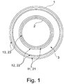
- the selected as an embodiment pipeline according to FIG. 1 is essentially formed by two concentrically arranged tubes 1, 2 with different diameters, between which a channel 3 for carrying out a microalgae suspension is formed.
- the outer tube 1 has in the exemplary embodiment, a wall thickness of 4 mm and an outer diameter of 450 mm.
- the outer tube 1 is provided with a 0.2 mm thick food-compatible layer, which is formed from polyethylene terephthalate (PET).
- PET polyethylene terephthalate
- the tube 1 is provided with a 0.2 mm thick UV barrier layer.
- the UV barrier layer 13 is formed in the embodiment of a provided with a UV blocker polycarbonate material.
- the inner tube 2 has in the embodiment, a wall thickness of 4 mm and an outer diameter of 350 mm and is as the outer tube 1 at its channel 3 facing outer surface with a 0.2 mm thick food-grade layer 22 and on its channel 3 facing away from the inner surface a 0.2 mm thick UV barrier layer provided.
- the channel 3 thus has a width of 45.5 mm.
- the diameter of the outer tube can be between 300 and 800 mm and the diameter of the inner tube between 200 and 700 mm.
- the width of the channel 3 for the microalgae suspension can be varied sufficiently, depending on the concentration of the algal suspension and the intensity of the light.
- the tubes 1, 2 are made of PMMA.
- the inner tube 2 has a constant wall thickness
- the large wall thickness is arranged in the lower tube area with a high liquid column (microalgae suspension 4) and correspondingly high liquid pressure.
- the wall thickness 2 decreases continuously and opens in the third section L3, where a low liquid column with a correspondingly low internal pressure is applied.
- the reduction of the wall thickness takes place on one side of the tube inside, whereby the tube has a constant outer diameter over its length.
- the inner tube 2 is filled in the embodiment with water 5. This water column serves to equalize the pressure with respect to the liquid column (microalgae suspension 4) and thereby minimizes the load on the inner tube, which can therefore have a constant wall thickness.
- FIG. 3 the wall thickness s of an outer tube 1 in an endless extrusion process is shown schematically over the time t of the extrusion process.
- two tubes 1 abut each other, which are separated from each other in a subsequent cutting process along the dividing line shown in dashed lines.
Landscapes
- Engineering & Computer Science (AREA)
- Health & Medical Sciences (AREA)
- Life Sciences & Earth Sciences (AREA)
- Wood Science & Technology (AREA)
- Organic Chemistry (AREA)
- Mechanical Engineering (AREA)
- Chemical & Material Sciences (AREA)
- Bioinformatics & Cheminformatics (AREA)
- Zoology (AREA)
- Biotechnology (AREA)
- Genetics & Genomics (AREA)
- Physics & Mathematics (AREA)
- Sustainable Development (AREA)
- Biomedical Technology (AREA)
- Thermal Sciences (AREA)
- Biochemistry (AREA)
- General Engineering & Computer Science (AREA)
- General Health & Medical Sciences (AREA)
- Microbiology (AREA)
- Clinical Laboratory Science (AREA)
- Molecular Biology (AREA)
- Laminated Bodies (AREA)
- Apparatus Associated With Microorganisms And Enzymes (AREA)
- Extrusion Moulding Of Plastics Or The Like (AREA)
Description
- Die Erfindung betrifft eine Rohrleitung zum Einsatz in einem Photobioreaktor zur Herstellung von Mikroalgenkonzentrat nach dem Oberbegriff des Patentanspruchs 1. Die Erfindung betrifft weiterhin ein Verfahren zur Herstellung eines solchen Rohres nach dem Patentanspruch 13.
- Eine Anlage zur Herstellung von Mikroalgenkonzentrat ist beispielsweise in der
DE 103 15 750 A1 beschrieben. Diese Anlage besteht aus einem Photobioreaktor zur Beschleunigung des Wachstums und der Vermehrung der Mikroalgen in einer Suspension mit einer Gruppe von Reaktorsegmenten, die transparente, parallel zueinander ausgerichtete Rohre besitzen sowie aus Behältern zur Anreicherung der Suspension mit Kohlendioxid und anderen Nährstoffen, aus Mitteln zur Abscheidung von Sauerstoff aus der Suspension sowie einer Erntevorrichtung mit Mitteln zur Abtrennung eines Mikroalgenkonzentrates. Dabei sind der Photobioreaktor, der Mischbehälter und die Mittel zum Abscheiden von Sauerstoff in einen Kreislauf eingebunden, der eine Pumpe aufweist. Die Rohre sind in den Reaktorsegmenten parallel zueinander und senkrecht ausgerichtet und in üblicher Weise dem einfallenden Tageslicht, einem äußeren Kunstlicht oder dem Licht von Lichtleitern mit streuendem Lichteffekt ausgesetzt. Nachteilig bei den zum Einsatz kommenden Rohren ist, dass die für die Photosynthese wirksame Oberfläche relativ klein ausgebildet ist, da lediglich der Rohraußenmantel als Lichteinfall- und -austrittsfläche zur Verfügung steht. In derEP 2 036 977 A1 wird hierzu vorgeschlagen, Durchflusstürme einzusetzen, welche durch zwei konzentrisch angeordnete, transluzente Rohre gebildet sind, mit einem Durchmesser von 0,8 bis 1,5 m und einer Höhe von 3 bis 5 m. Die Herstellung derartiger Türme stellt sich in der Praxis jedoch problematisch dar. Insbesondere bereitet der häufig in derartigen Anlagen verwendete Werkstoff Glas bei diesen Dimensionen statische Probleme, da die einzelnen Rohre vor dem Hintergrund der zu erwartenden Druckverhältnisse eine erhebliche Wandstärke aufweisen müssten. - In der
WO02099031 A1 - Mit der Erfindung ist eine Rohrleitung zum Einsatz in einem Photobioreaktor zur Herstellung von Mikroalgenkonzentrat geschaffen, die den auftretenden Druckverhältnissen standhält und zudem eine geringe Teilchen-Migrationsrate aufweist. Durch die Herstellung der beiden Rohre aus lichtdurchlässigem Kunststoff, wobei wenigstens das äußere Rohr über seine Länge wenigstens zwei Abschnitte mit unterschiedlicher Wandstärke aufweist, ist eine leichte und zugleich äußerst robuste Struktur geschaffen, die den auftretenden Druckverhältnissen standhält. Aufgrund des mit zunehmender Konzentratsäule abnehmenden Drucks weist das Rohr auch bei über seine Länge verminderter Wandstärke eine ausreichende Festigkeit auf.
- In Weiterbildung der Erfindung weist wenigstens ein Abschnitt eine sich linear verjüngende Wandstärke auf. Hierdurch sind Kerbwirkungen vermieden, wodurch die Belastbarkeit des Rohres erhöht ist. Dabei weisen die Rohre bevorzugt über ihre Länge einen konstanten Querschnitt auf.
- In Ausgestaltung der Erfindung sind wenigstens das äußere Rohr, bevorzugt beide Rohre, aus Polymethylmethacrylat (PMMA) hergestellt. Dieses Material ist hochtransparent, witterungsstabil, kostengünstig und gut verarbeitbar.
- In alternativer Ausgestaltung sind wenigstens das äußere Rohr, bevorzugt beide Rohre aus Polycarbonat hergestellt und auf ihrer dem Kanal zugewandten Seite mit einer lebensmittelkonformen Schicht und auf ihrer dem Kanal abgewandten Seite mit einer UV-Sperrschicht versehen. Durch die Beschichtung der Rohre auf ihrer jeweiligen dem Kanal zugewandten Seite mit einer lebensmittelkonformen Schicht ist eine geringe Migrationsrate gewährleistet. Durch die Beschichtung der Rohre auf ihrer jeweiligen dem Kanal abgewandten Seite mit einer UV-Sperrschicht ist eine Schädigung der Polycarbonat-Struktur durch UV-Licht verhindert, wodurch eine hohe Standzeit erzielt ist.
- In Weiterbildung der Erfindung weisen die beiden Rohre eine Lichtdurchlässigkeit von wenigstens 80%, vorzugsweise wenigstens 85% auf. Hierdurch ist ein hoher Lichteintrag ermöglicht, wodurch der Photosynthese-Prozess beschleunigt ist. Hierzu ist die UV-Sperrschicht bevorzugt derart ausgebildet, dass sie für Lichtwellen mit einer Wellenlänge von < 350 nm undurchlässig und mit einer Wellenlänge von 350 nm bis 700 nm durchlässig ist.
- In weiterer Ausgestaltung der Erfindung sind die Sperrschichten aus einem Polycarbonatmaterial gebildet, dem ein UV-Adsorber zugesetzt ist. Hierdurch ist ein homogener Auftrag der UV-Sperrschicht auf das Polycarbonat-Rohr ermöglicht.
- In weiterer Ausgestaltung der Erfindung sind die lebensmittelkonformen Schichten aus Polyethylenterephthalat (PET) oder Polycarbonat gebildet. Insbesondere durch die Verwendung von lebensmittelkonformen Polycarbonat, das vorzugsweise den Vorgaben der EU-Verordnung Nr. 10/211 genügt, ist eine homogene Beschichtung des Polycarbonat-Rohres ermöglicht. Dabei sind die UV-Sperrschichten und die lebensmittelkonformen Schichten mit dem jeweiligen Rohr vorzugsweise homogen und ohne Haftvermittler gebunden. Hierdurch sind die optischen Eigenschaften des Rohres möglicherweise beeinträchtigende Klebschichten vermieden.
- In weiterer Ausgestaltung der Erfindung sind Mittel zur Verringerung der Lichtbrechung angeordnet, die vorzugsweise durch Prismen und/oder Ziehstreifen gebildet sind. Hierdurch ist der Lichteintrag in den mit Mikroalgenkonzentrat durchströmten Kanal optimiert.
- Der Erfindung liegt weiterhin die Aufgabe zugrunde, ein Verfahren zur Herstellung eines Rohres für eine Rohrleitung zum Einsatz in einem Photobioreaktor zur Herstellung von Mikroalgenkonzentrat bereitzustellen, das kostengünstig herstellbar ist und den auftretenden Druckverhältnissen standhält.
- Gemäß der Erfindung wird diese Aufgabe durch ein Verfahren mit den Merkmalen des Patentanspruchs 13 gelöst. Dadurch, dass die Rohre in einem Endlos- Extrusionsprozess gefertigt werden, wobei zunächst ein Abschnitt mit einer ersten Wandstärke extrudiert wird, welche Wandstärke bei konstantem Rohraußendurchmesser über die Länge eines sich anschließenden zweiten Abschnitts linear reduziert wird, deren endseitig erreichte Wandstärke über einen sich anschließenden dritten Abschnitt konstant gehalten wird, wobei die vorgenannten Abschnitte nachfolgend in immer wieder umgekehrter Reihenfolge extrudiert werden, wodurch hintereinander jeweils zwei symmetrisch zueinander angeordnete Rohre gebildet sind, die in einem nachfolgenden Arbeitsschritt über einen Schneidprozess voneinander getrennt werden, ist eine kostengünstige Herstellung leichter und zugleich belastbarer Rohre mit kurzen Fertigungszeiten ermöglicht. Dabei werden die Rohre bevorzugt aus PMMA oder Polycarbonat hergestellt.
- In Weiterbildung der Erfindung werden die Rohre aus Polycarbonat gefertigt, wobei eine UV-Sperrschicht (13, 23), eine Polycarbonat-Strukturschicht (11, 21) und eine Lebensmittelkontaktschicht (12, 22) coextrudiert werden, wobei das coextrudierte Dreischichtrohr (1, 2) nachfolgend über temperierte und gestaffelte Kühlstufen abgekühlt wird. Dadurch, dass die UV-Schutzschicht die Polycarbonat-Strukturschicht und die Lebensmittelkontaktschicht coextrudiert werden, ist eine gleichmäßige, homogene Beschichtung über die gesamte Rohrlänge bewirkt. Dabei wird das coextrudierte Dreischichtrohr nachfolgend über temperierte und gestaffelte Kühlstufen abgekühlt, wodurch eine spannungsarme Abkühlung der so hergestellten Rohre bewirkt ist. Das so hergestellte Rohr weist eine geringe Teilchen-Migrationsrate auf.
- Andere Weiterbildungen und Ausgestaltungen der Erfindung sind in den übrigen Unteransprüchen angegeben. Ein Ausführungsbeispiel der Erfindung ist in der Zeichnung dargestellt und wird nachfolgend im Einzelnen beschrieben. Es zeigen:
- Figur 1
- die schematische Darstellung einer Rohrleitung zum Einsatz in einem Photobioreaktor zur Herstellung von Mikroalgenkonzentrat im Querschnitt;
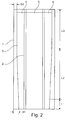
- Figur 2
- die schematische Darstellung einer Rohrleitung zum Einsatz in einem Photobioreaktor zur Herstellung von Mikroalgenkonzentrat in einer weiteren Ausführungsform im Längsschnitt und
- Figur 3
- die schematische Darstellung der variablen Wandstärke von endlos extrudierten Rohren für Rohrleitungen.
- Die als Ausführungsbeispiel gewählte Rohrleitung gemäß
Figur 1 ist im Wesentlichen gebildet durch zwei konzentrisch angeordnete Rohre 1, 2 mit unterschiedlichem Durchmesser, zwischen denen ein Kanal 3 zur Durchführung einer Mikroalgensuspension gebildet ist. Das Außenrohr 1 weist im Ausführungsbeispiel eine Wandstärke von 4 mm sowie einen Außendurchmesser von 450 mm auf. An seiner dem Kanal 3 zugewandten Innenmantelfläche ist das Außenrohr 1 mit einer 0,2 mm dicken lebensmittelkonformen Schicht versehen, die aus Polyethylenterephthalat (PET) gebildet ist. Auf seiner dem Kanal 3 abgewandten Außenmantelfläche ist das Rohr 1 mit einer 0,2 mm dicken UV-Sperr-Schicht versehen. Die UV-Sperrschicht 13 ist im Ausführungsbeispiel aus einem mit einem UV-Blocker versehenen Polycarbonat-Werkstoff gebildet. - Das Innenrohr 2 weist im Ausführungsbeispiel eine Wandstärke von 4 mm sowie einen Außendurchmesser von 350 mm auf und ist gleichsam dem Außenrohr 1 an seiner dem Kanal 3 zugewandten Außenmantelfläche mit einer 0,2 mm dicken lebensmittelkonformen Schicht 22 und an seiner dem Kanal 3 abgewandten Innenmantelfläche mit einer 0,2 mm dicken UV-Sperrschicht versehen. Der Kanal 3 weist somit eine Breite von 45,5 mm auf.
- Es hat sich gezeigt, dass vorteilhaft der Durchmesser des äußeren Rohres zwischen 300 und 800 mm und der Durchmesser des inneren Rohres zwischen 200 und 700 mm liegen kann. Damit kann die Breite des Kanals 3 für die Mikroalgensuspension ausreichend variiert werden, je nach Konzentration der Algensuspension und Stärke des Lichteinfalls.
- Im Ausführungsbeispiel gemäß
Figur 2 sind die Rohre 1, 2 aus PMMA hergestellt. Dabei weist das innere Rohr 2 eine konstante Wandstärke auf, wohingegen das äußere Rohr einen ersten Abschnitt L1 einer Wandstärke von s1 = 6 mm aufweist, an den sich ein zweiter Abschnitt L2 mit linear über seine Länge abnehmender Wandstärke anschließt, der wiederum in einen dritten Abschnitt L3 mit konstanter Wandstärke von s3 = 3 mm übergeht. Die große Wandstärke ist im unteren Rohrbereich mit hoher Flüssigkeitssäule (Mikroalgensuspension 4) und entsprechend hohem Flüssigkeitsdruck angeordnet. Im mittleren Abschnitt L2 nimmt die Wandstärke 2 kontinuierlich ab und mündet in dem dritten Abschnitt L3, wo eine niedrige Flüssigkeitssäule mit entsprechend geringem Innendruck anliegt. Die Reduzierung der Wandstärke erfolgt dabei einseitig an der Rohrinnenseite, wodurch das Rohr über seine Länge einen konstanten Außendurchmesser aufweist. Das innere Rohr 2 ist im Ausführungsbeispiel mit Wasser 5 gefüllt. Diese Wassersäule dient dem Druckausgleich gegenüber der Flüssigkeitssäule (Mikroalgensuspension 4) und minimiert hierdurch die Belastung des inneren Rohres, welches daher eine konstante Wandstärke aufweisen kann. - In
Figur 3 ist die Wanddicke s eines äußeren Rohres 1 in einem Endlos- Extrudierprozess schematisch über der Zeit t des Extrudiervorgangs dargestellt. Jeweils zwischen zwei benachbarten Abschnitten L3 bzw. zwei benachbarten Abschnitten L1 stoßen zwei Rohre 1 aneinander, welche in einem nachfolgenden Schneidprozess entlang der gestrichelt dargestellten Trennlinie voneinander getrennt werden.
Claims (15)
- Rohrleitung zur senkrecht ausgerichteten Anordnung in einem Photobioreaktor zur Herstellung von Mikroalgenkonzentrat, umfassend zwei konzentrisch angeordnete Rohre unterschiedlichen Durchmessers, zwischen denen ein Kanal für eine Mikroalgensuspension (4) gebildet ist, dadurch gekennzeichnet, dass die beiden Rohre (1, 2) aus lichtdurchlässigem Kunststoff hergestellt sind, wobei wenigstens das äußere Rohr (1) über seine Länge wenigstens zwei Abschnitte (L1, L2, L3) mit unterschiedlicher Wandstärke (s) aufweist.
- Rohrleitung nach Anspruch 1, dadurch gekennzeichnet, dass wenigstens ein Abschnitt (L2) eine sich linear verjüngende Wandstärke (s) aufweist.
- Rohrleistung nach Anspruch 1 oder 2, dadurch gekennzeichnet, dass die beiden Rohre (1, 2) über ihre Länge einen konstanten Außendurchmesser aufweisen.
- Rohrleitung nach einem der vorgenannten Ansprüche, dadurch gekennzeichnet, dass wenigstens das äußere Rohr (1), bevorzugt beide Rohre (1, 2) aus Polymethylmethacrylat (PMMA) hergestellt sind.
- Rohrleitung nach einem der Ansprüche 1 bis 3, dadurch gekennzeichnet, dass wenigstens das äußere Rohr (1), bevorzugt beide Rohre (1, 2) aus Polycarbonat hergestellt sind und auf ihrer dem Kanal zugewandten Seite mit einer lebensmittelkonformen Schicht (12, 22) und auf ihrer dem Kanal abgewandten Seite mit einer UV-Sperrschicht (13,23) versehen sind.
- Rohrleitung nach einem der vorgenannten Ansprüche, dadurch gekennzeichnet, dass die beiden Rohre (1, 2) eine Lichtdurchlässigkeit von wenigstens 80 Prozent, vorzugsweise wenigstens 85 Prozent aufweisen.
- Rohrleitung nach Anspruch 5 oder 6, dadurch gekennzeichnet, dass die UV-Sperrschichten (13, 23) derart ausgebildet sind, dass sie für Lichtwellen mit einer Wellenlänge von kleiner 350 nm undurchlässig und mit einer Wellenlänge von 350 nm bis 700 nm durchlässig sind.
- Rohrleitung nach Anspruch 7, dadurch gekennzeichnet, dass die UV-Sperrschichten (13, 23) aus einem Polycarbonatmaterial gebildet sind, dem ein UV-Adsorber zugesetzt ist.
- Rohrleitung nach einem der Ansprüche 5 bis 8, dadurch gekennzeichnet, dass die lebensmittelkonformen Schichten (12, 22) aus Polyethylenterephthalat oder Polycarbonat gebildet sind.
- Rohrleitung nach einem der Ansprüche 5 bis 9, dadurch gekennzeichnet, dass die UV-Sperrschichten (13, 23) und die lebensmittelkonformen Schichten (12, 22) mit dem jeweiligen Rohrgrundkörper (11, 21) homogen und ohne Haftvermittler gebunden sind.
- Rohrleitung nach einem der vorgenannten Ansprüche, dadurch gekennzeichnet, dass Mittel zur Verringerung der Lichtbrechung angeordnet sind.
- Rohrleitung nach Anspruch 11, dadurch gekennzeichnet, dass die Mittel zur Verringerung der Lichtbrechung durch Prismen und/oder Ziehstreifen gebildet sind.
- Verfahren zur Herstellung von Rohren (1) für Rohrleitungen nach einem der vorgenannten Ansprüche, dadurch gekennzeichnet, dass die Rohre (1) in einem Endlos- Extrusionsprozess gefertigt werden, wobei zunächst ein Abschnitt (L1) mit einer ersten Wandstärke (s1) extrudiert wird, welche Wandstärke bei konstantem Rohraußendurchmesser über die Länge eines sich anschließenden zweiten Abschnitts (L2) linear reduziert wird, deren endseitig erreichte Wandstärke (s3) über einen sich anschließenden dritten Abschnitt (L3) konstant gehalten wird, wobei die vorgenannten Abschnitte (L1, L2, L3) nachfolgend in immer wieder umgekehrter Reihenfolge extrudiert werden, wodurch hintereinander jeweils zwei symmetrisch zueinander angeordnete Rohre (1) gebildet sind, die in einem nachfolgenden Arbeitsschritt über einen Schneidprozess voneinander getrennt werden.
- Verfahren nach Anspruch 13, dadurch gekennzeichnet, dass die Rohre aus Polymethylmethacrylat (PMMA) gefertigt werden.
- Verfahren nach Anspruch 13, dadurch gekennzeichnet, dass die Rohre aus Polycarbonat gefertigt werden, wobei eine UV-Sperrschicht (13,23), eine Polycarbonat-Strukturschicht (11, 21) und eine Lebensmittelkontaktschicht- (12, 22) coextrudiert werden, wobei das coextrudierte Dreischichtrohr (1, 2) nachfolgend über temperierte und gestaffelte Kühlstufen abgekühlt wird.
Applications Claiming Priority (2)
| Application Number | Priority Date | Filing Date | Title |
|---|---|---|---|
| DE102013106478.7A DE102013106478A1 (de) | 2013-06-20 | 2013-06-20 | Rohrleitung zum Einsatz in einem Photobioreaktor |
| PCT/EP2013/074985 WO2014202159A1 (de) | 2013-06-20 | 2013-11-28 | Rohrleitung zum einsatz in einem photobioreaktor |
Publications (2)
| Publication Number | Publication Date |
|---|---|
| EP3011006A1 EP3011006A1 (de) | 2016-04-27 |
| EP3011006B1 true EP3011006B1 (de) | 2017-05-31 |
Family
ID=49765466
Family Applications (1)
| Application Number | Title | Priority Date | Filing Date |
|---|---|---|---|
| EP13805300.4A Not-in-force EP3011006B1 (de) | 2013-06-20 | 2013-11-28 | Rohrleitung zum einsatz in einem photobioreaktor |
Country Status (4)
| Country | Link |
|---|---|
| EP (1) | EP3011006B1 (de) |
| DE (1) | DE102013106478A1 (de) |
| ES (1) | ES2638552T3 (de) |
| WO (1) | WO2014202159A1 (de) |
Family Cites Families (6)
| Publication number | Priority date | Publication date | Assignee | Title |
|---|---|---|---|---|
| DE1209282B (de) * | 1961-02-25 | 1966-01-20 | Anger Kunststoff | Verfahren und Vorrichtung zur Herstellung von Rohren mit Aufweitungen und/oder Verdickungen |
| WO2002099031A1 (en) * | 2001-06-01 | 2002-12-12 | Yamaha Hatsudoki Kabushiki Kaisha | Device and method for cultivating micro algae |
| DE10315750A1 (de) | 2003-04-04 | 2004-10-21 | Stadtwerke Stollberg | Anlage zur Herstellung von Mikroalgenkonzentrat |
| ES2288132B1 (es) | 2006-06-09 | 2008-11-01 | Bernard A.J. Stroiazzo-Mougin | Fotoconvertidor de energia para la obtencion de biocombustibles. |
| US9376656B2 (en) * | 2009-03-30 | 2016-06-28 | Brad W. Bartilson | Photobioreactor system and method for the growth of algae for biofuels and related products |
| EP2284218A1 (de) * | 2009-07-27 | 2011-02-16 | Georg Fischer DEKA GmbH | Polymerzusammensetzung für Photobioreaktoren |
-
2013
- 2013-06-20 DE DE102013106478.7A patent/DE102013106478A1/de not_active Withdrawn
- 2013-11-28 ES ES13805300.4T patent/ES2638552T3/es active Active
- 2013-11-28 EP EP13805300.4A patent/EP3011006B1/de not_active Not-in-force
- 2013-11-28 WO PCT/EP2013/074985 patent/WO2014202159A1/de not_active Ceased
Non-Patent Citations (1)
| Title |
|---|
| None * |
Also Published As
| Publication number | Publication date |
|---|---|
| ES2638552T3 (es) | 2017-10-23 |
| WO2014202159A1 (de) | 2014-12-24 |
| DE102013106478A1 (de) | 2014-12-24 |
| EP3011006A1 (de) | 2016-04-27 |
Similar Documents
| Publication | Publication Date | Title |
|---|---|---|
| DE3686772T2 (de) | Hochorientiertes verstaerkungselement aus kunststoff und verfahren zu dessen herstellung. | |
| DE3403635C2 (de) | ||
| DE102011014063A1 (de) | Wandbauelement | |
| EP1147803A1 (de) | Vorrichtung zum Filtern und Trennen von insbesondere biologisch organischen Strömungsmedien | |
| DE102007057613A1 (de) | Extruderschnecke für einen Schneckenextruder | |
| WO1998017889A1 (de) | Lichtleitplatten | |
| DE69202884T2 (de) | Verfahren und Vorrichtung zum Herstellen von Rohren aus thermoplastischen, mit Fasern steuerbarer Ausrichtung verstärkten Werkstoffen. | |
| DE102009023121A1 (de) | Träger für einen Siliziumblock | |
| EP2484602B1 (de) | Umreifungsbänder aus nachwachsenden Rohstoffen | |
| WO2014202159A1 (de) | Rohrleitung zum einsatz in einem photobioreaktor | |
| EP1915559B1 (de) | Hohlkörper mit doppelter sperrschicht | |
| EP3630483B1 (de) | Verbundscheibe und verfahren zum herstellen der verbundscheibe | |
| DE102008015337B4 (de) | Absorberrohr eines Solarkollektors und Solarkollektor | |
| DE102014103858A1 (de) | Reaktorsäule zum Einsatz in einem Photobioreaktor | |
| DE69715602T2 (de) | Mehrschichtiges rohr | |
| DE102010061794A1 (de) | Verfahren und Vorrichtung zum Umformen von Metallen und Kunststoffen | |
| EP3530450A1 (de) | Mehrschichtige kraftfahrzeug-rohrleitung | |
| DE60221513T2 (de) | Verfahren zur herstellung eines mit flansch versehenen elements und ein mit flansch versehenes element | |
| DE102013111970A1 (de) | Verfahren zur Verlegung eines langen Rohrstrangs | |
| DE102012211651A1 (de) | Verfahren zur Herstellung eines Wickelrohrs | |
| EP2873507B1 (de) | Verfahren zur kontinuierlichen fertigung von kunststoffrohren | |
| DE202011004546U1 (de) | Lichtdurchlässige Betonelemente | |
| DE102004015391B4 (de) | Vakuumkalibriervorrichtung | |
| DE102007030914A1 (de) | Formstück aus Kunststoff | |
| DE6929493U (de) | Mehrkanalrohr |
Legal Events
| Date | Code | Title | Description |
|---|---|---|---|
| PUAI | Public reference made under article 153(3) epc to a published international application that has entered the european phase |
Free format text: ORIGINAL CODE: 0009012 |
|
| 17P | Request for examination filed |
Effective date: 20151028 |
|
| AK | Designated contracting states |
Kind code of ref document: A1 Designated state(s): AL AT BE BG CH CY CZ DE DK EE ES FI FR GB GR HR HU IE IS IT LI LT LU LV MC MK MT NL NO PL PT RO RS SE SI SK SM TR |
|
| AX | Request for extension of the european patent |
Extension state: BA ME |
|
| DAX | Request for extension of the european patent (deleted) | ||
| GRAP | Despatch of communication of intention to grant a patent |
Free format text: ORIGINAL CODE: EPIDOSNIGR1 |
|
| RIC1 | Information provided on ipc code assigned before grant |
Ipc: B29C 47/06 20060101ALI20170228BHEP Ipc: C12M 1/12 20060101ALI20170228BHEP Ipc: B29C 47/00 20060101ALI20170228BHEP Ipc: C12M 1/00 20060101AFI20170228BHEP Ipc: B29D 23/00 20060101ALI20170228BHEP |
|
| INTG | Intention to grant announced |
Effective date: 20170313 |
|
| RIN1 | Information on inventor provided before grant (corrected) |
Inventor name: BARTON, PHILIP Inventor name: KAISER, HUBERTUS Inventor name: KAISER, HANS |
|
| GRAS | Grant fee paid |
Free format text: ORIGINAL CODE: EPIDOSNIGR3 |
|
| GRAA | (expected) grant |
Free format text: ORIGINAL CODE: 0009210 |
|
| AK | Designated contracting states |
Kind code of ref document: B1 Designated state(s): AL AT BE BG CH CY CZ DE DK EE ES FI FR GB GR HR HU IE IS IT LI LT LU LV MC MK MT NL NO PL PT RO RS SE SI SK SM TR |
|
| REG | Reference to a national code |
Ref country code: CH Ref legal event code: EP Ref country code: GB Ref legal event code: FG4D Free format text: NOT ENGLISH |
|
| REG | Reference to a national code |
Ref country code: AT Ref legal event code: REF Ref document number: 897486 Country of ref document: AT Kind code of ref document: T Effective date: 20170615 |
|
| REG | Reference to a national code |
Ref country code: IE Ref legal event code: FG4D Free format text: LANGUAGE OF EP DOCUMENT: GERMAN |
|
| REG | Reference to a national code |
Ref country code: DE Ref legal event code: R096 Ref document number: 502013007406 Country of ref document: DE |
|
| REG | Reference to a national code |
Ref country code: NL Ref legal event code: MP Effective date: 20170531 |
|
| REG | Reference to a national code |
Ref country code: LT Ref legal event code: MG4D |
|
| REG | Reference to a national code |
Ref country code: ES Ref legal event code: FG2A Ref document number: 2638552 Country of ref document: ES Kind code of ref document: T3 Effective date: 20171023 |
|
| PG25 | Lapsed in a contracting state [announced via postgrant information from national office to epo] |
Ref country code: HR Free format text: LAPSE BECAUSE OF FAILURE TO SUBMIT A TRANSLATION OF THE DESCRIPTION OR TO PAY THE FEE WITHIN THE PRESCRIBED TIME-LIMIT Effective date: 20170531 Ref country code: FI Free format text: LAPSE BECAUSE OF FAILURE TO SUBMIT A TRANSLATION OF THE DESCRIPTION OR TO PAY THE FEE WITHIN THE PRESCRIBED TIME-LIMIT Effective date: 20170531 Ref country code: GR Free format text: LAPSE BECAUSE OF FAILURE TO SUBMIT A TRANSLATION OF THE DESCRIPTION OR TO PAY THE FEE WITHIN THE PRESCRIBED TIME-LIMIT Effective date: 20170901 Ref country code: LT Free format text: LAPSE BECAUSE OF FAILURE TO SUBMIT A TRANSLATION OF THE DESCRIPTION OR TO PAY THE FEE WITHIN THE PRESCRIBED TIME-LIMIT Effective date: 20170531 Ref country code: NO Free format text: LAPSE BECAUSE OF FAILURE TO SUBMIT A TRANSLATION OF THE DESCRIPTION OR TO PAY THE FEE WITHIN THE PRESCRIBED TIME-LIMIT Effective date: 20170831 |
|
| REG | Reference to a national code |
Ref country code: FR Ref legal event code: PLFP Year of fee payment: 5 |
|
| PG25 | Lapsed in a contracting state [announced via postgrant information from national office to epo] |
Ref country code: IS Free format text: LAPSE BECAUSE OF FAILURE TO SUBMIT A TRANSLATION OF THE DESCRIPTION OR TO PAY THE FEE WITHIN THE PRESCRIBED TIME-LIMIT Effective date: 20170930 Ref country code: BG Free format text: LAPSE BECAUSE OF FAILURE TO SUBMIT A TRANSLATION OF THE DESCRIPTION OR TO PAY THE FEE WITHIN THE PRESCRIBED TIME-LIMIT Effective date: 20170831 Ref country code: LV Free format text: LAPSE BECAUSE OF FAILURE TO SUBMIT A TRANSLATION OF THE DESCRIPTION OR TO PAY THE FEE WITHIN THE PRESCRIBED TIME-LIMIT Effective date: 20170531 Ref country code: RS Free format text: LAPSE BECAUSE OF FAILURE TO SUBMIT A TRANSLATION OF THE DESCRIPTION OR TO PAY THE FEE WITHIN THE PRESCRIBED TIME-LIMIT Effective date: 20170531 Ref country code: SE Free format text: LAPSE BECAUSE OF FAILURE TO SUBMIT A TRANSLATION OF THE DESCRIPTION OR TO PAY THE FEE WITHIN THE PRESCRIBED TIME-LIMIT Effective date: 20170531 Ref country code: NL Free format text: LAPSE BECAUSE OF FAILURE TO SUBMIT A TRANSLATION OF THE DESCRIPTION OR TO PAY THE FEE WITHIN THE PRESCRIBED TIME-LIMIT Effective date: 20170531 |
|
| PG25 | Lapsed in a contracting state [announced via postgrant information from national office to epo] |
Ref country code: EE Free format text: LAPSE BECAUSE OF FAILURE TO SUBMIT A TRANSLATION OF THE DESCRIPTION OR TO PAY THE FEE WITHIN THE PRESCRIBED TIME-LIMIT Effective date: 20170531 Ref country code: CZ Free format text: LAPSE BECAUSE OF FAILURE TO SUBMIT A TRANSLATION OF THE DESCRIPTION OR TO PAY THE FEE WITHIN THE PRESCRIBED TIME-LIMIT Effective date: 20170531 Ref country code: RO Free format text: LAPSE BECAUSE OF FAILURE TO SUBMIT A TRANSLATION OF THE DESCRIPTION OR TO PAY THE FEE WITHIN THE PRESCRIBED TIME-LIMIT Effective date: 20170531 Ref country code: DK Free format text: LAPSE BECAUSE OF FAILURE TO SUBMIT A TRANSLATION OF THE DESCRIPTION OR TO PAY THE FEE WITHIN THE PRESCRIBED TIME-LIMIT Effective date: 20170531 Ref country code: SK Free format text: LAPSE BECAUSE OF FAILURE TO SUBMIT A TRANSLATION OF THE DESCRIPTION OR TO PAY THE FEE WITHIN THE PRESCRIBED TIME-LIMIT Effective date: 20170531 |
|
| PG25 | Lapsed in a contracting state [announced via postgrant information from national office to epo] |
Ref country code: PL Free format text: LAPSE BECAUSE OF FAILURE TO SUBMIT A TRANSLATION OF THE DESCRIPTION OR TO PAY THE FEE WITHIN THE PRESCRIBED TIME-LIMIT Effective date: 20170531 Ref country code: SM Free format text: LAPSE BECAUSE OF FAILURE TO SUBMIT A TRANSLATION OF THE DESCRIPTION OR TO PAY THE FEE WITHIN THE PRESCRIBED TIME-LIMIT Effective date: 20170531 |
|
| REG | Reference to a national code |
Ref country code: DE Ref legal event code: R097 Ref document number: 502013007406 Country of ref document: DE |
|
| PLBE | No opposition filed within time limit |
Free format text: ORIGINAL CODE: 0009261 |
|
| STAA | Information on the status of an ep patent application or granted ep patent |
Free format text: STATUS: NO OPPOSITION FILED WITHIN TIME LIMIT |
|
| 26N | No opposition filed |
Effective date: 20180301 |
|
| PG25 | Lapsed in a contracting state [announced via postgrant information from national office to epo] |
Ref country code: SI Free format text: LAPSE BECAUSE OF FAILURE TO SUBMIT A TRANSLATION OF THE DESCRIPTION OR TO PAY THE FEE WITHIN THE PRESCRIBED TIME-LIMIT Effective date: 20170531 |
|
| PG25 | Lapsed in a contracting state [announced via postgrant information from national office to epo] |
Ref country code: MC Free format text: LAPSE BECAUSE OF FAILURE TO SUBMIT A TRANSLATION OF THE DESCRIPTION OR TO PAY THE FEE WITHIN THE PRESCRIBED TIME-LIMIT Effective date: 20170531 |
|
| GBPC | Gb: european patent ceased through non-payment of renewal fee |
Effective date: 20171128 |
|
| PG25 | Lapsed in a contracting state [announced via postgrant information from national office to epo] |
Ref country code: LI Free format text: LAPSE BECAUSE OF NON-PAYMENT OF DUE FEES Effective date: 20171130 Ref country code: CH Free format text: LAPSE BECAUSE OF NON-PAYMENT OF DUE FEES Effective date: 20171130 |
|
| PG25 | Lapsed in a contracting state [announced via postgrant information from national office to epo] |
Ref country code: LU Free format text: LAPSE BECAUSE OF NON-PAYMENT OF DUE FEES Effective date: 20171128 |
|
| REG | Reference to a national code |
Ref country code: BE Ref legal event code: MM Effective date: 20171130 |
|
| REG | Reference to a national code |
Ref country code: IE Ref legal event code: MM4A |
|
| PG25 | Lapsed in a contracting state [announced via postgrant information from national office to epo] |
Ref country code: MT Free format text: LAPSE BECAUSE OF FAILURE TO SUBMIT A TRANSLATION OF THE DESCRIPTION OR TO PAY THE FEE WITHIN THE PRESCRIBED TIME-LIMIT Effective date: 20170531 |
|
| PG25 | Lapsed in a contracting state [announced via postgrant information from national office to epo] |
Ref country code: IE Free format text: LAPSE BECAUSE OF NON-PAYMENT OF DUE FEES Effective date: 20171128 Ref country code: IT Free format text: LAPSE BECAUSE OF NON-PAYMENT OF DUE FEES Effective date: 20171128 |
|
| PG25 | Lapsed in a contracting state [announced via postgrant information from national office to epo] |
Ref country code: BE Free format text: LAPSE BECAUSE OF NON-PAYMENT OF DUE FEES Effective date: 20171130 Ref country code: GB Free format text: LAPSE BECAUSE OF NON-PAYMENT OF DUE FEES Effective date: 20171128 |
|
| PGFP | Annual fee paid to national office [announced via postgrant information from national office to epo] |
Ref country code: FR Payment date: 20181127 Year of fee payment: 6 |
|
| PG25 | Lapsed in a contracting state [announced via postgrant information from national office to epo] |
Ref country code: HU Free format text: LAPSE BECAUSE OF FAILURE TO SUBMIT A TRANSLATION OF THE DESCRIPTION OR TO PAY THE FEE WITHIN THE PRESCRIBED TIME-LIMIT; INVALID AB INITIO Effective date: 20131128 |
|
| PG25 | Lapsed in a contracting state [announced via postgrant information from national office to epo] |
Ref country code: CY Free format text: LAPSE BECAUSE OF FAILURE TO SUBMIT A TRANSLATION OF THE DESCRIPTION OR TO PAY THE FEE WITHIN THE PRESCRIBED TIME-LIMIT Effective date: 20170531 |
|
| PG25 | Lapsed in a contracting state [announced via postgrant information from national office to epo] |
Ref country code: MK Free format text: LAPSE BECAUSE OF FAILURE TO SUBMIT A TRANSLATION OF THE DESCRIPTION OR TO PAY THE FEE WITHIN THE PRESCRIBED TIME-LIMIT Effective date: 20170531 |
|
| REG | Reference to a national code |
Ref country code: AT Ref legal event code: MM01 Ref document number: 897486 Country of ref document: AT Kind code of ref document: T Effective date: 20181128 |
|
| PG25 | Lapsed in a contracting state [announced via postgrant information from national office to epo] |
Ref country code: AT Free format text: LAPSE BECAUSE OF NON-PAYMENT OF DUE FEES Effective date: 20181128 |
|
| PGFP | Annual fee paid to national office [announced via postgrant information from national office to epo] |
Ref country code: DE Payment date: 20191205 Year of fee payment: 7 |
|
| PGFP | Annual fee paid to national office [announced via postgrant information from national office to epo] |
Ref country code: ES Payment date: 20191216 Year of fee payment: 7 |
|
| PG25 | Lapsed in a contracting state [announced via postgrant information from national office to epo] |
Ref country code: TR Free format text: LAPSE BECAUSE OF FAILURE TO SUBMIT A TRANSLATION OF THE DESCRIPTION OR TO PAY THE FEE WITHIN THE PRESCRIBED TIME-LIMIT Effective date: 20170531 |
|
| PG25 | Lapsed in a contracting state [announced via postgrant information from national office to epo] |
Ref country code: PT Free format text: LAPSE BECAUSE OF FAILURE TO SUBMIT A TRANSLATION OF THE DESCRIPTION OR TO PAY THE FEE WITHIN THE PRESCRIBED TIME-LIMIT Effective date: 20170531 |
|
| PG25 | Lapsed in a contracting state [announced via postgrant information from national office to epo] |
Ref country code: AL Free format text: LAPSE BECAUSE OF FAILURE TO SUBMIT A TRANSLATION OF THE DESCRIPTION OR TO PAY THE FEE WITHIN THE PRESCRIBED TIME-LIMIT Effective date: 20170531 |
|
| PG25 | Lapsed in a contracting state [announced via postgrant information from national office to epo] |
Ref country code: FR Free format text: LAPSE BECAUSE OF NON-PAYMENT OF DUE FEES Effective date: 20191130 |
|
| REG | Reference to a national code |
Ref country code: DE Ref legal event code: R119 Ref document number: 502013007406 Country of ref document: DE |
|
| PG25 | Lapsed in a contracting state [announced via postgrant information from national office to epo] |
Ref country code: DE Free format text: LAPSE BECAUSE OF NON-PAYMENT OF DUE FEES Effective date: 20210601 |
|
| REG | Reference to a national code |
Ref country code: ES Ref legal event code: FD2A Effective date: 20220202 |
|
| PG25 | Lapsed in a contracting state [announced via postgrant information from national office to epo] |
Ref country code: ES Free format text: LAPSE BECAUSE OF NON-PAYMENT OF DUE FEES Effective date: 20201129 |