EP3010797B1 - Dichtungsanordnung für ein propellerschaft - Google Patents
Dichtungsanordnung für ein propellerschaft Download PDFInfo
- Publication number
- EP3010797B1 EP3010797B1 EP14730882.9A EP14730882A EP3010797B1 EP 3010797 B1 EP3010797 B1 EP 3010797B1 EP 14730882 A EP14730882 A EP 14730882A EP 3010797 B1 EP3010797 B1 EP 3010797B1
- Authority
- EP
- European Patent Office
- Prior art keywords
- housing
- graphite
- seal
- sealing
- driveshaft
- Prior art date
- Legal status (The legal status is an assumption and is not a legal conclusion. Google has not performed a legal analysis and makes no representation as to the accuracy of the status listed.)
- Active
Links
Images

Classifications
-
- B—PERFORMING OPERATIONS; TRANSPORTING
- B63—SHIPS OR OTHER WATERBORNE VESSELS; RELATED EQUIPMENT
- B63H—MARINE PROPULSION OR STEERING
- B63H23/00—Transmitting power from propulsion power plant to propulsive elements
- B63H23/32—Other parts
- B63H23/36—Shaft tubes
-
- B—PERFORMING OPERATIONS; TRANSPORTING
- B63—SHIPS OR OTHER WATERBORNE VESSELS; RELATED EQUIPMENT
- B63H—MARINE PROPULSION OR STEERING
- B63H23/00—Transmitting power from propulsion power plant to propulsive elements
- B63H23/32—Other parts
- B63H23/321—Bearings or seals specially adapted for propeller shafts
- B63H2023/327—Sealings specially adapted for propeller shafts or stern tubes
Definitions
- the invention relates to a method for protecting a seal assembly in case of fire.
- the stern tube seal seals the output shaft substantially at the point where it penetrates an outer wall of the hull and dips into the ambient water.
- the sealing requirements for bulkhead seals are completely different from those of a stern tube seal.
- the stern tube seal must always be completely tight.
- the bulkhead seal which is not exposed to water during normal operation, tolerates slight leakage as long as the leak can be compensated for by a bilge pump in the rare event of water ingress.
- sealing seals also called labyrinth seals, are often used in bulkhead sealing; in stern tube seals such gap seals are not considered due to the increased density requirement.
- the seal comprises several rubber-elastic components.
- a sealing tube is inflated if necessary, thus creating a sealing effect between the shaft and the housing wall.
- the rubber-elastic parts are destroyed immediately in a fire, which eliminates the sealing effect.
- a bulkhead seal which has sealing rings made of graphite.
- This seal uses the principle of the gap seal.
- the sealing rings have a temperature resistance of about 300 ° C to max. 600 ° C on. Sealing arrangements with several sealing rings are in the DE 43 23 470 A1 and the WO 2004/090392 A1 described.
- the object of the present invention is to ensure the tightness of such seal assemblies in case of fire.
- the object underlying the invention is achieved by a method according to claim 1.
- the invention is also applicable for protecting a stern tube sealing arrangement according to claim 5.
- Embodiments are also conceivable in which the outer seals, that is to say the first and third seals, which delimit the annular chambers, in particular with respect to the surroundings, are formed by other seals (not by graphite). Then, however, at least one additional, in particular carbonaceous, fuel element is provided for generating the protective atmosphere, which is likewise arranged on a boundary of the annular chamber.
- the essence of the invention is essentially to arrange the drive shaft two annular chambers adjacent to each other. It has been shown in experiments that then seen from the fire second graphite seal has a much higher life, compared with an arrangement in which this graphite seal is not surrounded on the back of such an annular chamber.
- thermo resistance of the graphite sealing rings used can be significantly increased by oxygen removal, in particular to values above 1000 ° C. This property makes itself the Invention in which a reduction of oxygen in the region of the graphite sealing rings is achieved.
- the temperature resistance in an oxygen-containing atmosphere depending on the type of graphite used is only 300 ° C to 600 ° C; It can therefore be generated quite quickly exhaust gases by burning off the graphite;
- another important feature of graphite is that the temperature resistance increases abruptly to over 1,000 ° C when the oxygen is removed from the graphite.
- the source of fire facing first graphite seal is therefore initially sacrificed.
- the downstream, namely arranged between the two annular chamber, second graphite seal then remains protected from combustion under the protective atmosphere generated by the exhaust gases.
- the downstream third sealing ring now prevents oxygen-containing fresh air from passing in the direction of the second annular chamber in the direction of the second graphite sealing ring.
- the third seal does not necessarily have to be made of graphite, since it is not exposed to the fire; However, it has been found to be advantageous to use a symmetrical arrangement here, since thus the fire resistance can be secured from both sides.
- the graphite gaskets have also been found to be particularly suitable for such sealing arrangements for the following reasons. First, they allow a fairly simple installation. Because the graphite gaskets can be formed by a plurality, in particular two radially divided graphite ring parts. These can be placed radially on the drive shaft, without the need for threading through the drive shaft by an always closed sealing ring. The graphite gaskets themselves have lubricating properties; After a short phase of running in, the graphite sealing rings are thus very tight against the drive shaft, without there being appreciable friction losses or even damage to the drive shaft. By a play-bearing storage of the graphite gaskets within the housing radial movements of the drive shaft can be easily compensated.
- the housing is preferably multi-part and has a plurality, in particular three, axially divided housing parts.
- Individual housing parts, in particular the two axially outer housing parts, are thermally insulated from each other.
- an inner housing part can represent a thermal barrier for reducing the heat transfer between the two outer housing parts.
- the inner housing part made of a material, such as a carbon composite material can be produced, which has a poorer thermal conductivity than the material from which the outer housing parts are formed, for example, stainless steel.
- the inner housing part may be formed by a mounting ring, to which the housing is attached to the partition wall.
- a thermal insulating layer can be applied between two housing parts, preferably made of mica. Traveling quite thin slices of mica form a sufficient heat barrier, which also also acts electrically insulating. Individual or all of the housing parts can additionally be covered with a heat protection layer, in particular made of stone or glass wool.
- a possible application of such a method is in a claimed manner for protecting a stern tube seal assembly with a stern tube seal according to claim 5.
- a sealing arrangement described above and the associated method for protecting this seal assembly is in fact set in series with the stern tube seal.
- the stern tube seal on the water side (outside) certainly will not be confronted with a fire. From the side of the fuselage, the sealing arrangement according to the invention is now precluded from being subjected to fire.
- the fire protection is carried out by a fire-protected housing wall of the protective housing; the fire protection can be done easily by packing the protective housing by rock wool, etc.
- the fire protection is carried out by the seal assembly in the above manner.
- the protective housing is also attached to the outer wall, to which the stern tube seal is attached.
- the stern tube seal can seal an outside opening 23 of the protective housing 20.
- the outer wall 16 and the protective housing 20 surrounds the stern tube seal 9 on the fuselage side. The water side, the stern tube seal 9 is still without sheathing.
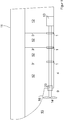
- FIG. 1 shows the cross section through a conventional hull 11.
- the hull 11 has a plurality of separate watertight compartments 12.
- the watertight compartments 12 are separated by internal partitions 3, the so-called bulkheads. Should one of the watertight compartments 12 run full of water through a leak in the outer wall 16 of the hull 11, the dividing walls 3 prevent the water from entering the other watertight compartments 12 either.
- the marine engine 13 is arranged. Via a drive shaft 4, the drive power is transmitted from the marine engine 13 to the propeller 14, which is arranged outside the hull 11 in the ambient water 15. In this case, the drive shaft 4 penetrates a plurality of the watertight compartments 12.
- so-called bulkhead seals 1 are provided as sealing arrangements. which seal the shaft passages. Normally, these bulkhead seals 1 do not have to prevent the penetration of water, since the watertight compartments 12 are filled with air.
- a stern tube seal 9 seals a drive shaft 4 with respect to an outer wall 16 of the ship's hull 11.
- a stern tube seal 9 must always be completely watertight. There are no leaks tolerated because the stern tube seal 9 is acted upon by the operation of the ship from one side with ambient water 15. To meet this requirement include the stern tube seals rubber-elastic sealing elements, which are destroyed immediately in a fire, however.
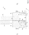
- FIG. 2 now shows a protected according to the invention seal assembly in the form of a bulkhead seal.
- the bulkhead seal 1 has a housing which has three axially separate housing parts 5 1 , 5 2 , 5 3 .
- the bulkhead seal 1 is fixed in the region of the opening 2 on the partition wall 3.
- the two outer housing parts 5 1 , 5 3 are each flanged to the central housing part 5 2 .
- the middle housing part 5 2 which performs the task of a mounting ring is made of a carbon composite material, ie a thermally poorly conductive material and thus provides a thermal barrier between the outer housing parts 5 1 , 5 3.
- the housing parts 5 are annularly encircling the Axle A of the drive shaft 4 are formed and are waterproof to each other and flanged together on the partition wall 3.
- a total of three annular gaps 17 are arranged, which also annularly about the axis A circulating.
- these annular gaps 17 each have a graphite sealing ring 6 is arranged.
- the graphite sealing rings are provided with the reference numerals 6 1 , 6 2 , 6 3 .
- mica rings 26 are provided which additionally or alternatively cause the thermal insulation of the housing parts to form the mounting ring made of carbon composite material.
- the three graphite sealing rings 6 are arranged axially next to one another. There are thus provided two axially outer graphite sealing rings 6 1 and 6 3 , as well as an inner graphite sealing ring 6 2 .
- the first and outer graphite sealing ring 6 1 and the second and inner graphite sealing ring 6 2 seals a first inner annular chamber 8 1 , which is further limited by the drive shaft 4 and the housing 5, in the present case specifically of the first housing part 5 1 .
- a second annular chamber 8 2 is formed Immediately adjacent to this first annular chamber 8 1 , a second annular chamber 8 2 is formed.
- This second annular chamber 8 2 is bounded by the second and inner graphite sealing ring 6 2 , by the third and outer graphite sealing ring 6 3 and by the drive shaft 4 and the housing 5, in the present case concretely by all three housing parts 5 1 , 5 2 , 5 3 .
- the resulting combustion gases which mainly comprise carbon dioxide, now flow into the first annular chamber 8 1 and ensure that there is a largely oxygen-free atmosphere with an at most negligible oxygen content.
- the temperature resistance of the inner graphite seal increases, depending on the type of graphite used, abruptly to over 1,000 ° C; The exposure to fire can therefore not cause any significant damage to this inner graphite sealing ring.
- each of the three graphite sealing rings 6 has a predetermined task to solve.
- the closest to the source of fire first graphite seal 6 1 has the function of a sacrificial element that generates by continuous burning exhaust gases that form a protective atmosphere for another graphite seal.
- the subsequent second graphite sealing ring 6 2 is then the graphite sealing ring to be protected, which in fact should continue to ensure the sealing effect.
- the subsequent third graphite sealing ring 6 3 serves to ensure that a protective atmosphere can also be built up and maintained in the second annular chamber 8 1 .
- this third graphite seal can also take over sealing functions.
- the same protective effect results when the fire exposure comes from the other department 12 2 .
- the graphite sealing rings 6 are radially divided and thus have two or more graphite sealing ring parts.
- the graphite sealing ring parts are acted upon by spring elements, which are arranged in particular in the annular gap 17 radially outside of the graphite sealing rings 6, radially inwardly to the drive shaft 4.
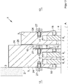
- FIG. 3 the area of the hull 11 in the region of the stern tube seal 9 is shown in detail.
- the stern tube seal 9 is flanged, possibly with the aid of a mounting ring, from the inside to the opening 21 of the outer wall 16.
- a protective housing 20 is provided, which is also flanged to the opening 21 of the outer wall 16 and is held there sealing. An outside, ie the ambient water 15 facing opening 23 of the protective housing 20 is sealed by the stern tube seal 9.
- the protective housing 20 now comprises a hull-side opening 22, which is aligned coaxially with the stern tube seal 9 and through which the drive shaft 4 is guided.
- This hull-side opening 22 is sealed by a bulkhead seal 1 according to the invention.
- the protective housing 23 is formed fireproof and closed tightly.
- the interior of the protective housing 20, which is further limited by the stern tube seal 9 and the bulkhead seal 1 and possibly the outer wall 16 next to the protective housing 20, is free of possible sources of fire; it is preferably completely empty, apart from possibly refractory objects (fire resistance> 1000 ° C), such as screws.
- An immediate fire exposure of the stern tube seal 9 from the interior of the protective housing 20 is therefore initially excluded; a fire from outside is excluded anyway, since there is the ambient water 15.
- the protective housing 20 may, however, be formed of a steel structure and is then readily fireproof.
- the protective housing 20 may alternatively or additionally be sheathed with a protective sheath, in particular rockwool.
- a penetration of the fire in the protective housing 20 in the region of the fuselage-side opening 22 is also prevented by the inventive bulkhead seal 1.
- the stern tube seal 9 itself is still not fireproof with this solution; However, there is a refractory stern tube seal assembly 19 comprising the protective housing 20, the bulkhead seal 1, the stern tube seal 9 and possibly the drive shaft 4.
- Das Protective housing 20 may be formed in several parts, whereby the assembly is facilitated. After installation, however, it must be completely watertight and gas-tight, with the exception of the opening which is sealed by the bulkhead seal 1.
- a drive shaft may be any shaft through which torque is transmitted; This also includes those waves, which are referred to as the output shaft.
Landscapes
- Chemical & Material Sciences (AREA)
- Engineering & Computer Science (AREA)
- Combustion & Propulsion (AREA)
- Mechanical Engineering (AREA)
- Ocean & Marine Engineering (AREA)
- Sealing Devices (AREA)
- Gasket Seals (AREA)
Applications Claiming Priority (2)
| Application Number | Priority Date | Filing Date | Title |
|---|---|---|---|
| DE102013106407.8A DE102013106407B4 (de) | 2013-06-19 | 2013-06-19 | Dichtungsanordnung |
| PCT/EP2014/062530 WO2014202516A1 (de) | 2013-06-19 | 2014-06-16 | Dichtungsanordnung für ein propellerschaft |
Publications (2)
| Publication Number | Publication Date |
|---|---|
| EP3010797A1 EP3010797A1 (de) | 2016-04-27 |
| EP3010797B1 true EP3010797B1 (de) | 2018-12-12 |
Family
ID=50972706
Family Applications (1)
| Application Number | Title | Priority Date | Filing Date |
|---|---|---|---|
| EP14730882.9A Active EP3010797B1 (de) | 2013-06-19 | 2014-06-16 | Dichtungsanordnung für ein propellerschaft |
Country Status (4)
| Country | Link |
|---|---|
| EP (1) | EP3010797B1 (es) |
| DE (1) | DE102013106407B4 (es) |
| ES (1) | ES2715019T3 (es) |
| WO (1) | WO2014202516A1 (es) |
Cited By (1)
| Publication number | Priority date | Publication date | Assignee | Title |
|---|---|---|---|---|
| US11655014B2 (en) | 2019-09-12 | 2023-05-23 | Johnson Propeller Co., Inc. | Boat shaft seal system |
Family Cites Families (8)
| Publication number | Priority date | Publication date | Assignee | Title |
|---|---|---|---|---|
| CH234499A (de) * | 1943-03-24 | 1944-09-30 | Huhn Gustav | Stopfbüchsenpackung mit Dichtungsringen für Schiffspropellerwellen. |
| FR896960A (fr) * | 1943-05-03 | 1945-03-08 | Gustav Huhn | Garniture à bague de frottement en charbon cuirassée pour tubes d'étambot de navires |
| GB597002A (en) * | 1944-08-10 | 1948-01-15 | Ettore Bugatti | Propeller shaft bearing assembly for ships |
| DE3220595A1 (de) | 1982-06-01 | 1983-12-01 | Howaldtswerke-Deutsche Werft Ag Hamburg Und Kiel, 2300 Kiel | Hilfsdichtung fuer wellen, insbesondere propellerwellen |
| FR2673908A1 (fr) * | 1991-03-13 | 1992-09-18 | Delmotte Didier | Dispositif de maintien et de controle de l'etancheite et de la lubrification des lignes d'arbres de transmission des moteurs de bateaux. |
| US5152704A (en) * | 1991-05-09 | 1992-10-06 | Team Scarab, Inc. | Water jet propulsion unit |
| DE4323470C2 (de) * | 1993-07-14 | 1996-07-11 | Atlas Copco Energas | Dichtungsanordnung für die Abdichtung einer Wellendurchführung an der Schottwand eines Schiffes |
| KR100496990B1 (ko) * | 2003-04-11 | 2005-06-23 | 주식회사 신원기계부품 | 회전축용 밀폐장치 |
-
2013
- 2013-06-19 DE DE102013106407.8A patent/DE102013106407B4/de active Active
-
2014
- 2014-06-16 ES ES14730882T patent/ES2715019T3/es active Active
- 2014-06-16 EP EP14730882.9A patent/EP3010797B1/de active Active
- 2014-06-16 WO PCT/EP2014/062530 patent/WO2014202516A1/de not_active Ceased
Non-Patent Citations (1)
| Title |
|---|
| None * |
Cited By (1)
| Publication number | Priority date | Publication date | Assignee | Title |
|---|---|---|---|---|
| US11655014B2 (en) | 2019-09-12 | 2023-05-23 | Johnson Propeller Co., Inc. | Boat shaft seal system |
Also Published As
| Publication number | Publication date |
|---|---|
| ES2715019T3 (es) | 2019-05-31 |
| WO2014202516A1 (de) | 2014-12-24 |
| DE102013106407B4 (de) | 2019-09-12 |
| DE102013106407A1 (de) | 2014-12-24 |
| EP3010797A1 (de) | 2016-04-27 |
Similar Documents
| Publication | Publication Date | Title |
|---|---|---|
| DE102009058411A1 (de) | Abgasturbolader | |
| EP3644402B1 (de) | Batteriegehäuse umfassend ein ventil zum druckausgleich und/oder drucküberlastabbau | |
| EP3010797B1 (de) | Dichtungsanordnung für ein propellerschaft | |
| DE2022978A1 (de) | Anordnung mit einer in einem Gehaeuse untergebrachten Einrichtung | |
| DE69932685T2 (de) | Glühsensor - keramische flache Platte | |
| DE102008033429B4 (de) | Feststofftriebwerk | |
| EP0891471B1 (de) | Verfahren und vorrichtung zum schubausgleich bei einer turbomaschine | |
| DE2348501A1 (de) | Zuendeinrichtung fuer gasturbinentriebwerk | |
| DE60104329T2 (de) | Wellenabdichtung | |
| DE3014297A1 (de) | Turbolader fuer eine verbrennungskraftmaschine | |
| DE102009052644B4 (de) | Wärmeabschirmungsblech für Abgasanlagen von Kraftfahrzeugen | |
| DE3419352C2 (de) | Durchführung für mindestens eine Leitung, insbesondere ein elektrisches Kabel | |
| DE102005033991A1 (de) | Branschutzsystem für eine oder mehrere Versorgungsleitungen | |
| DE2732779A1 (de) | Hubkolben-drehzylinder-motor (hd-motor) | |
| EP3006677B1 (de) | Gasturbine mit wenigstens zwei koaxial zueinander angeordneten und zumindest bereichsweise als hohlwellen ausgebildeten wellen | |
| DE3529905A1 (de) | Befestigungsanordnung fuer keramische nachverbrennungskammern | |
| EP3649427B1 (de) | Vorrichtung zur erzeugung von blitz- und/oder knalleffekten | |
| DE3816663C2 (es) | ||
| DE3036398A1 (de) | Schutzvorrichtung fuer rohrleitungen | |
| DE2443989A1 (de) | Rotations-vorwaermwaermetauscher | |
| DE3924270A1 (de) | Abdichtungsvorrichtung fuer rotierende wellen, insbesondere stevenrohrabdichtung fuer schiffsschraubenwellen | |
| DE117899C (es) | ||
| DE102013107495A1 (de) | Abschirmeinrichtung | |
| DE19755238A1 (de) | Ventilstangenführung | |
| DE102016115512A1 (de) | Zylinderkurbelgehäuse für eine Brennkraftmaschine mit Kunststoffgehäuse und Metall-Insert |
Legal Events
| Date | Code | Title | Description |
|---|---|---|---|
| PUAI | Public reference made under article 153(3) epc to a published international application that has entered the european phase |
Free format text: ORIGINAL CODE: 0009012 |
|
| 17P | Request for examination filed |
Effective date: 20160111 |
|
| AK | Designated contracting states |
Kind code of ref document: A1 Designated state(s): AL AT BE BG CH CY CZ DE DK EE ES FI FR GB GR HR HU IE IS IT LI LT LU LV MC MK MT NL NO PL PT RO RS SE SI SK SM TR |
|
| AX | Request for extension of the european patent |
Extension state: BA ME |
|
| DAX | Request for extension of the european patent (deleted) | ||
| GRAP | Despatch of communication of intention to grant a patent |
Free format text: ORIGINAL CODE: EPIDOSNIGR1 |
|
| STAA | Information on the status of an ep patent application or granted ep patent |
Free format text: STATUS: GRANT OF PATENT IS INTENDED |
|
| INTG | Intention to grant announced |
Effective date: 20180823 |
|
| GRAS | Grant fee paid |
Free format text: ORIGINAL CODE: EPIDOSNIGR3 |
|
| GRAA | (expected) grant |
Free format text: ORIGINAL CODE: 0009210 |
|
| STAA | Information on the status of an ep patent application or granted ep patent |
Free format text: STATUS: THE PATENT HAS BEEN GRANTED |
|
| RAP1 | Party data changed (applicant data changed or rights of an application transferred) |
Owner name: MUELLER, TOBIAS |
|
| RIN1 | Information on inventor provided before grant (corrected) |
Inventor name: MUELLER, TOBIAS |
|
| AK | Designated contracting states |
Kind code of ref document: B1 Designated state(s): AL AT BE BG CH CY CZ DE DK EE ES FI FR GB GR HR HU IE IS IT LI LT LU LV MC MK MT NL NO PL PT RO RS SE SI SK SM TR |
|
| REG | Reference to a national code |
Ref country code: GB Ref legal event code: FG4D Free format text: NOT ENGLISH |
|
| REG | Reference to a national code |
Ref country code: CH Ref legal event code: EP |
|
| REG | Reference to a national code |
Ref country code: AT Ref legal event code: REF Ref document number: 1075618 Country of ref document: AT Kind code of ref document: T Effective date: 20181215 |
|
| REG | Reference to a national code |
Ref country code: DE Ref legal event code: R096 Ref document number: 502014010323 Country of ref document: DE |
|
| REG | Reference to a national code |
Ref country code: IE Ref legal event code: FG4D Free format text: LANGUAGE OF EP DOCUMENT: GERMAN |
|
| REG | Reference to a national code |
Ref country code: SE Ref legal event code: TRGR |
|
| REG | Reference to a national code |
Ref country code: NL Ref legal event code: FP |
|
| REG | Reference to a national code |
Ref country code: LT Ref legal event code: MG4D |
|
| PG25 | Lapsed in a contracting state [announced via postgrant information from national office to epo] |
Ref country code: LT Free format text: LAPSE BECAUSE OF FAILURE TO SUBMIT A TRANSLATION OF THE DESCRIPTION OR TO PAY THE FEE WITHIN THE PRESCRIBED TIME-LIMIT Effective date: 20181212 Ref country code: LV Free format text: LAPSE BECAUSE OF FAILURE TO SUBMIT A TRANSLATION OF THE DESCRIPTION OR TO PAY THE FEE WITHIN THE PRESCRIBED TIME-LIMIT Effective date: 20181212 Ref country code: BG Free format text: LAPSE BECAUSE OF FAILURE TO SUBMIT A TRANSLATION OF THE DESCRIPTION OR TO PAY THE FEE WITHIN THE PRESCRIBED TIME-LIMIT Effective date: 20190312 Ref country code: HR Free format text: LAPSE BECAUSE OF FAILURE TO SUBMIT A TRANSLATION OF THE DESCRIPTION OR TO PAY THE FEE WITHIN THE PRESCRIBED TIME-LIMIT Effective date: 20181212 |
|
| REG | Reference to a national code |
Ref country code: NO Ref legal event code: T2 Effective date: 20181212 |
|
| PG25 | Lapsed in a contracting state [announced via postgrant information from national office to epo] |
Ref country code: AL Free format text: LAPSE BECAUSE OF FAILURE TO SUBMIT A TRANSLATION OF THE DESCRIPTION OR TO PAY THE FEE WITHIN THE PRESCRIBED TIME-LIMIT Effective date: 20181212 Ref country code: GR Free format text: LAPSE BECAUSE OF FAILURE TO SUBMIT A TRANSLATION OF THE DESCRIPTION OR TO PAY THE FEE WITHIN THE PRESCRIBED TIME-LIMIT Effective date: 20190313 Ref country code: RS Free format text: LAPSE BECAUSE OF FAILURE TO SUBMIT A TRANSLATION OF THE DESCRIPTION OR TO PAY THE FEE WITHIN THE PRESCRIBED TIME-LIMIT Effective date: 20181212 |
|
| PG25 | Lapsed in a contracting state [announced via postgrant information from national office to epo] |
Ref country code: PL Free format text: LAPSE BECAUSE OF FAILURE TO SUBMIT A TRANSLATION OF THE DESCRIPTION OR TO PAY THE FEE WITHIN THE PRESCRIBED TIME-LIMIT Effective date: 20181212 Ref country code: PT Free format text: LAPSE BECAUSE OF FAILURE TO SUBMIT A TRANSLATION OF THE DESCRIPTION OR TO PAY THE FEE WITHIN THE PRESCRIBED TIME-LIMIT Effective date: 20190412 Ref country code: CZ Free format text: LAPSE BECAUSE OF FAILURE TO SUBMIT A TRANSLATION OF THE DESCRIPTION OR TO PAY THE FEE WITHIN THE PRESCRIBED TIME-LIMIT Effective date: 20181212 |
|
| PG25 | Lapsed in a contracting state [announced via postgrant information from national office to epo] |
Ref country code: RO Free format text: LAPSE BECAUSE OF FAILURE TO SUBMIT A TRANSLATION OF THE DESCRIPTION OR TO PAY THE FEE WITHIN THE PRESCRIBED TIME-LIMIT Effective date: 20181212 Ref country code: EE Free format text: LAPSE BECAUSE OF FAILURE TO SUBMIT A TRANSLATION OF THE DESCRIPTION OR TO PAY THE FEE WITHIN THE PRESCRIBED TIME-LIMIT Effective date: 20181212 Ref country code: SM Free format text: LAPSE BECAUSE OF FAILURE TO SUBMIT A TRANSLATION OF THE DESCRIPTION OR TO PAY THE FEE WITHIN THE PRESCRIBED TIME-LIMIT Effective date: 20181212 Ref country code: IS Free format text: LAPSE BECAUSE OF FAILURE TO SUBMIT A TRANSLATION OF THE DESCRIPTION OR TO PAY THE FEE WITHIN THE PRESCRIBED TIME-LIMIT Effective date: 20190412 Ref country code: SK Free format text: LAPSE BECAUSE OF FAILURE TO SUBMIT A TRANSLATION OF THE DESCRIPTION OR TO PAY THE FEE WITHIN THE PRESCRIBED TIME-LIMIT Effective date: 20181212 |
|
| REG | Reference to a national code |
Ref country code: DE Ref legal event code: R097 Ref document number: 502014010323 Country of ref document: DE |
|
| PLBE | No opposition filed within time limit |
Free format text: ORIGINAL CODE: 0009261 |
|
| STAA | Information on the status of an ep patent application or granted ep patent |
Free format text: STATUS: NO OPPOSITION FILED WITHIN TIME LIMIT |
|
| PG25 | Lapsed in a contracting state [announced via postgrant information from national office to epo] |
Ref country code: DK Free format text: LAPSE BECAUSE OF FAILURE TO SUBMIT A TRANSLATION OF THE DESCRIPTION OR TO PAY THE FEE WITHIN THE PRESCRIBED TIME-LIMIT Effective date: 20181212 Ref country code: SI Free format text: LAPSE BECAUSE OF FAILURE TO SUBMIT A TRANSLATION OF THE DESCRIPTION OR TO PAY THE FEE WITHIN THE PRESCRIBED TIME-LIMIT Effective date: 20181212 |
|
| 26N | No opposition filed |
Effective date: 20190913 |
|
| PG25 | Lapsed in a contracting state [announced via postgrant information from national office to epo] |
Ref country code: MC Free format text: LAPSE BECAUSE OF FAILURE TO SUBMIT A TRANSLATION OF THE DESCRIPTION OR TO PAY THE FEE WITHIN THE PRESCRIBED TIME-LIMIT Effective date: 20181212 |
|
| REG | Reference to a national code |
Ref country code: CH Ref legal event code: PL |
|
| REG | Reference to a national code |
Ref country code: BE Ref legal event code: MM Effective date: 20190630 |
|
| PG25 | Lapsed in a contracting state [announced via postgrant information from national office to epo] |
Ref country code: TR Free format text: LAPSE BECAUSE OF FAILURE TO SUBMIT A TRANSLATION OF THE DESCRIPTION OR TO PAY THE FEE WITHIN THE PRESCRIBED TIME-LIMIT Effective date: 20181212 |
|
| PG25 | Lapsed in a contracting state [announced via postgrant information from national office to epo] |
Ref country code: IE Free format text: LAPSE BECAUSE OF NON-PAYMENT OF DUE FEES Effective date: 20190616 |
|
| PG25 | Lapsed in a contracting state [announced via postgrant information from national office to epo] |
Ref country code: BE Free format text: LAPSE BECAUSE OF NON-PAYMENT OF DUE FEES Effective date: 20190630 Ref country code: LI Free format text: LAPSE BECAUSE OF NON-PAYMENT OF DUE FEES Effective date: 20190630 Ref country code: CH Free format text: LAPSE BECAUSE OF NON-PAYMENT OF DUE FEES Effective date: 20190630 Ref country code: LU Free format text: LAPSE BECAUSE OF NON-PAYMENT OF DUE FEES Effective date: 20190616 |
|
| REG | Reference to a national code |
Ref country code: AT Ref legal event code: MM01 Ref document number: 1075618 Country of ref document: AT Kind code of ref document: T Effective date: 20190616 |
|
| PGFP | Annual fee paid to national office [announced via postgrant information from national office to epo] |
Ref country code: SE Payment date: 20200625 Year of fee payment: 7 |
|
| PG25 | Lapsed in a contracting state [announced via postgrant information from national office to epo] |
Ref country code: AT Free format text: LAPSE BECAUSE OF NON-PAYMENT OF DUE FEES Effective date: 20190616 |
|
| PG25 | Lapsed in a contracting state [announced via postgrant information from national office to epo] |
Ref country code: CY Free format text: LAPSE BECAUSE OF FAILURE TO SUBMIT A TRANSLATION OF THE DESCRIPTION OR TO PAY THE FEE WITHIN THE PRESCRIBED TIME-LIMIT Effective date: 20181212 |
|
| PG25 | Lapsed in a contracting state [announced via postgrant information from national office to epo] |
Ref country code: HU Free format text: LAPSE BECAUSE OF FAILURE TO SUBMIT A TRANSLATION OF THE DESCRIPTION OR TO PAY THE FEE WITHIN THE PRESCRIBED TIME-LIMIT; INVALID AB INITIO Effective date: 20140616 Ref country code: MT Free format text: LAPSE BECAUSE OF FAILURE TO SUBMIT A TRANSLATION OF THE DESCRIPTION OR TO PAY THE FEE WITHIN THE PRESCRIBED TIME-LIMIT Effective date: 20181212 |
|
| REG | Reference to a national code |
Ref country code: SE Ref legal event code: EUG |
|
| PG25 | Lapsed in a contracting state [announced via postgrant information from national office to epo] |
Ref country code: SE Free format text: LAPSE BECAUSE OF NON-PAYMENT OF DUE FEES Effective date: 20210617 |
|
| PG25 | Lapsed in a contracting state [announced via postgrant information from national office to epo] |
Ref country code: MK Free format text: LAPSE BECAUSE OF FAILURE TO SUBMIT A TRANSLATION OF THE DESCRIPTION OR TO PAY THE FEE WITHIN THE PRESCRIBED TIME-LIMIT Effective date: 20181212 |
|
| PGFP | Annual fee paid to national office [announced via postgrant information from national office to epo] |
Ref country code: FI Payment date: 20250630 Year of fee payment: 12 |
|
| PGFP | Annual fee paid to national office [announced via postgrant information from national office to epo] |
Ref country code: DE Payment date: 20250623 Year of fee payment: 12 |
|
| PGFP | Annual fee paid to national office [announced via postgrant information from national office to epo] |
Ref country code: NL Payment date: 20250627 Year of fee payment: 12 |
|
| PGFP | Annual fee paid to national office [announced via postgrant information from national office to epo] |
Ref country code: FR Payment date: 20250630 Year of fee payment: 12 |
|
| PGFP | Annual fee paid to national office [announced via postgrant information from national office to epo] |
Ref country code: ES Payment date: 20250718 Year of fee payment: 12 |
|
| PGFP | Annual fee paid to national office [announced via postgrant information from national office to epo] |
Ref country code: NO Payment date: 20250722 Year of fee payment: 12 |
|
| PGFP | Annual fee paid to national office [announced via postgrant information from national office to epo] |
Ref country code: IT Payment date: 20250731 Year of fee payment: 12 |
|
| PGFP | Annual fee paid to national office [announced via postgrant information from national office to epo] |
Ref country code: GB Payment date: 20250724 Year of fee payment: 12 |