EP3010076B1 - Flachplattentyp-festoxid-brennstoffzellenstapel und flachplattentyp-festoxidbrennstoffzellenstapelmodul - Google Patents
Flachplattentyp-festoxid-brennstoffzellenstapel und flachplattentyp-festoxidbrennstoffzellenstapelmodul Download PDFInfo
- Publication number
- EP3010076B1 EP3010076B1 EP15152175.4A EP15152175A EP3010076B1 EP 3010076 B1 EP3010076 B1 EP 3010076B1 EP 15152175 A EP15152175 A EP 15152175A EP 3010076 B1 EP3010076 B1 EP 3010076B1
- Authority
- EP
- European Patent Office
- Prior art keywords
- fuel
- cathode
- anode
- flow channel
- output hole
- Prior art date
- Legal status (The legal status is an assumption and is not a legal conclusion. Google has not performed a legal analysis and makes no representation as to the accuracy of the status listed.)
- Not-in-force
Links
Images




Classifications
-
- H—ELECTRICITY
- H01—ELECTRIC ELEMENTS
- H01M—PROCESSES OR MEANS, e.g. BATTERIES, FOR THE DIRECT CONVERSION OF CHEMICAL ENERGY INTO ELECTRICAL ENERGY
- H01M8/00—Fuel cells; Manufacture thereof
- H01M8/002—Shape, form of a fuel cell
- H01M8/006—Flat
-
- H—ELECTRICITY
- H01—ELECTRIC ELEMENTS
- H01M—PROCESSES OR MEANS, e.g. BATTERIES, FOR THE DIRECT CONVERSION OF CHEMICAL ENERGY INTO ELECTRICAL ENERGY
- H01M8/00—Fuel cells; Manufacture thereof
- H01M8/04—Auxiliary arrangements, e.g. for control of pressure or for circulation of fluids
- H01M8/04082—Arrangements for control of reactant parameters, e.g. pressure or concentration
- H01M8/04201—Reactant storage and supply, e.g. means for feeding, pipes
-
- H—ELECTRICITY
- H01—ELECTRIC ELEMENTS
- H01M—PROCESSES OR MEANS, e.g. BATTERIES, FOR THE DIRECT CONVERSION OF CHEMICAL ENERGY INTO ELECTRICAL ENERGY
- H01M8/00—Fuel cells; Manufacture thereof
- H01M8/02—Details
- H01M8/0202—Collectors; Separators, e.g. bipolar separators; Interconnectors
- H01M8/0258—Collectors; Separators, e.g. bipolar separators; Interconnectors characterised by the configuration of channels, e.g. by the flow field of the reactant or coolant
- H01M8/0263—Collectors; Separators, e.g. bipolar separators; Interconnectors characterised by the configuration of channels, e.g. by the flow field of the reactant or coolant having meandering or serpentine paths
-
- H—ELECTRICITY
- H01—ELECTRIC ELEMENTS
- H01M—PROCESSES OR MEANS, e.g. BATTERIES, FOR THE DIRECT CONVERSION OF CHEMICAL ENERGY INTO ELECTRICAL ENERGY
- H01M8/00—Fuel cells; Manufacture thereof
- H01M8/02—Details
- H01M8/0271—Sealing or supporting means around electrodes, matrices or membranes
-
- H—ELECTRICITY
- H01—ELECTRIC ELEMENTS
- H01M—PROCESSES OR MEANS, e.g. BATTERIES, FOR THE DIRECT CONVERSION OF CHEMICAL ENERGY INTO ELECTRICAL ENERGY
- H01M8/00—Fuel cells; Manufacture thereof
- H01M8/02—Details
- H01M8/0271—Sealing or supporting means around electrodes, matrices or membranes
- H01M8/0273—Sealing or supporting means around electrodes, matrices or membranes with sealing or supporting means in the form of a frame
-
- H—ELECTRICITY
- H01—ELECTRIC ELEMENTS
- H01M—PROCESSES OR MEANS, e.g. BATTERIES, FOR THE DIRECT CONVERSION OF CHEMICAL ENERGY INTO ELECTRICAL ENERGY
- H01M8/00—Fuel cells; Manufacture thereof
- H01M8/10—Fuel cells with solid electrolytes
- H01M8/12—Fuel cells with solid electrolytes operating at high temperature, e.g. with stabilised ZrO2 electrolyte
- H01M8/124—Fuel cells with solid electrolytes operating at high temperature, e.g. with stabilised ZrO2 electrolyte characterised by the process of manufacturing or by the material of the electrolyte
- H01M8/1246—Fuel cells with solid electrolytes operating at high temperature, e.g. with stabilised ZrO2 electrolyte characterised by the process of manufacturing or by the material of the electrolyte the electrolyte consisting of oxides
-
- H—ELECTRICITY
- H01—ELECTRIC ELEMENTS
- H01M—PROCESSES OR MEANS, e.g. BATTERIES, FOR THE DIRECT CONVERSION OF CHEMICAL ENERGY INTO ELECTRICAL ENERGY
- H01M8/00—Fuel cells; Manufacture thereof
- H01M8/24—Grouping of fuel cells, e.g. stacking of fuel cells
-
- H—ELECTRICITY
- H01—ELECTRIC ELEMENTS
- H01M—PROCESSES OR MEANS, e.g. BATTERIES, FOR THE DIRECT CONVERSION OF CHEMICAL ENERGY INTO ELECTRICAL ENERGY
- H01M8/00—Fuel cells; Manufacture thereof
- H01M8/24—Grouping of fuel cells, e.g. stacking of fuel cells
- H01M8/241—Grouping of fuel cells, e.g. stacking of fuel cells with solid or matrix-supported electrolytes
- H01M8/2425—High-temperature cells with solid electrolytes
- H01M8/2432—Grouping of unit cells of planar configuration
-
- H—ELECTRICITY
- H01—ELECTRIC ELEMENTS
- H01M—PROCESSES OR MEANS, e.g. BATTERIES, FOR THE DIRECT CONVERSION OF CHEMICAL ENERGY INTO ELECTRICAL ENERGY
- H01M8/00—Fuel cells; Manufacture thereof
- H01M8/24—Grouping of fuel cells, e.g. stacking of fuel cells
- H01M8/2465—Details of groupings of fuel cells
- H01M8/2483—Details of groupings of fuel cells characterised by internal manifolds
-
- H—ELECTRICITY
- H01—ELECTRIC ELEMENTS
- H01M—PROCESSES OR MEANS, e.g. BATTERIES, FOR THE DIRECT CONVERSION OF CHEMICAL ENERGY INTO ELECTRICAL ENERGY
- H01M8/00—Fuel cells; Manufacture thereof
- H01M8/10—Fuel cells with solid electrolytes
- H01M8/12—Fuel cells with solid electrolytes operating at high temperature, e.g. with stabilised ZrO2 electrolyte
- H01M2008/1293—Fuel cells with solid oxide electrolytes
-
- H—ELECTRICITY
- H01—ELECTRIC ELEMENTS
- H01M—PROCESSES OR MEANS, e.g. BATTERIES, FOR THE DIRECT CONVERSION OF CHEMICAL ENERGY INTO ELECTRICAL ENERGY
- H01M2300/00—Electrolytes
- H01M2300/0017—Non-aqueous electrolytes
- H01M2300/0065—Solid electrolytes
- H01M2300/0068—Solid electrolytes inorganic
- H01M2300/0071—Oxides
-
- Y—GENERAL TAGGING OF NEW TECHNOLOGICAL DEVELOPMENTS; GENERAL TAGGING OF CROSS-SECTIONAL TECHNOLOGIES SPANNING OVER SEVERAL SECTIONS OF THE IPC; TECHNICAL SUBJECTS COVERED BY FORMER USPC CROSS-REFERENCE ART COLLECTIONS [XRACs] AND DIGESTS
- Y02—TECHNOLOGIES OR APPLICATIONS FOR MITIGATION OR ADAPTATION AGAINST CLIMATE CHANGE
- Y02E—REDUCTION OF GREENHOUSE GAS [GHG] EMISSIONS, RELATED TO ENERGY GENERATION, TRANSMISSION OR DISTRIBUTION
- Y02E60/00—Enabling technologies; Technologies with a potential or indirect contribution to GHG emissions mitigation
- Y02E60/30—Hydrogen technology
- Y02E60/50—Fuel cells
-
- Y—GENERAL TAGGING OF NEW TECHNOLOGICAL DEVELOPMENTS; GENERAL TAGGING OF CROSS-SECTIONAL TECHNOLOGIES SPANNING OVER SEVERAL SECTIONS OF THE IPC; TECHNICAL SUBJECTS COVERED BY FORMER USPC CROSS-REFERENCE ART COLLECTIONS [XRACs] AND DIGESTS
- Y02—TECHNOLOGIES OR APPLICATIONS FOR MITIGATION OR ADAPTATION AGAINST CLIMATE CHANGE
- Y02P—CLIMATE CHANGE MITIGATION TECHNOLOGIES IN THE PRODUCTION OR PROCESSING OF GOODS
- Y02P70/00—Climate change mitigation technologies in the production process for final industrial or consumer products
- Y02P70/50—Manufacturing or production processes characterised by the final manufactured product
Definitions
- the invention relates to a flat plate type solid oxide fuel cell stack unit and flat plate type solid oxide fuel cell stack module, and more particularly to the cell stack unit and the cell stack module that are characterized on a reduced size, high efficiency, easy packing and assembly, and can easily and modularly vary the stack arrangement so as to meet the different specifications of the generation systems.
- the solid oxide fuel cell is an energy conversion apparatus that utilizes the electrochemical reaction to convert the fuel into the respective electric energy for output.
- the energy conversion efficiency of the SOFC generation system can be raised up to 80-90%.
- the application size of the SOFC generation system can be small or portable sized for household, medical facilities, communities and so on, and may be large sized to serve a generation plant.
- a conventional fuell cell as disclosed in document US 2012 /052410 A1 comprises a fuel distributor, an oxidizer distributor, and a solid electrolyte operatively arranged between the fuel distributor and the oxidizer distributor.
- the fuel cell disclosed therein is a kind of bipolar flat plate design having flow channel structures on a surface thereof.
- Document US 6 051 330 A describes another design of a conventional SOFC comprising a rectangular anode plate and a rectangular cathode plate that are respectively formed with four first through holes located respectively to four corners thereof, and another through holes located at a center thereof.
- the rectangular cell unit has four through holes located at respective corners thereof and further through holes located at a center thereof, wherein a cathode layer is disposed at one side thereof and an anode layer is disposed at the other side thereof, wherein the through holes at the corners are aligned respectively in positions.
- the conventional SOFC stack is assembled by laminating with end plates, panel frames, cell units, seal materials and metal contact layers. Obviously, such a manufacturing process is complicated and can only produce a larger-size cell stack module. Hence, the complexity in assembling the aforesaid conventional SOFC stack would be inevitable, and also the generation system having the SOFC stack is quite possible to have a low electric generation per unit volume.
- the flat plate type solid oxide fuel cell stack unit comprises an anode plate, a cathode plate, a cell unit, an anode metal net, a cathode metal net, at least one anode sealing material and at least one cathode sealing material.
- the anode plate formed as a rectangle has a first flow channel structured on a surface thereof, four first fuel input holes located respectively to four corners thereof, and a first fuel output hole located at a center thereof.
- the cathode plate shaped as a rectangle has a second flow channel structured on a surface thereof, four second fuel input holes located at respective corners thereof, a second fuel output hole located at a center thereof, a plurality of second air input grooves disposed along a lateral side thereof, and a plurality of second air output grooves disposed along another lateral side thereof opposing to the lateral side, wherein the second air input grooves, the second air output grooves and the second flow channel are all communicative in space.
- the cell unit shaped as a rectangle has four third fuel input holes located at respective corners thereof, a third fuel output hole located at a center thereof, a cathode layer disposed at one side thereof to face the second flow channel, an anode layer disposed at another side thereof opposing to the side to face the first flow channel, wherein the four first fuel input holes, the four second fuel input holes and the four third fuel input holes are aligned respectively in positions, wherein the first fuel output hole, the second fuel output hole and the third fuel output hole are aligned respectively in positions.
- the anode metal net is located between the anode plate and the cell unit.
- the cathode metal net is located between the cathode plate and the cell unit.
- the at least one anode sealing material is disposed between the anode plate and the cell unit to surround the first fuel input holes, the first fuel output hole, the first flow channel, the cell unit and the anode metal net.
- the at least one cathode sealing material is disposed between the cathode plate and the cell unit to surround the second fuel input holes, the second fuel output hole, the second flow channel, the cell unit and the cathode metal net.
- the flat plate type solid oxide fuel cell stack module is obtained by stacking a plurality of the aforesaid flat plate type solid oxide fuel cell stack units.
- the flat plate type solid oxide fuel cell stack module comprises an anode plate, a cathode plate, a plurality of connection plates and a plurality of cell sets.
- the anode plate formed as a rectangle has a first flow channel structured on a surface thereof, four first fuel input holes located respectively to four corners thereof, and a first fuel output hole located at a center thereof.
- the cathode plate shaped as a rectangle has a second flow channel structured on a surface thereof, four second fuel input holes located at respective corners thereof, a second fuel output hole located at a center thereof, a plurality of second air input grooves disposed along a lateral side thereof, and a plurality of second air output grooves disposed along another lateral side thereof opposing to the lateral side, wherein the second air input grooves, the second air output grooves and the second flow channel are all communicative in space.
- connection plates is shaped as a rectangle and has four eighth fuel input holes located at respective corners thereof, an eighth fuel output hole located at a center thereof, an anode flow channel area disposed on one side thereof, a cathode flow channel area disposed on another side thereof opposing to the side, a plurality of eighth air input grooves disposed along a lateral side of the side thereof having the cathode flow channel area, and a plurality of eighth air output grooves disposed along another lateral side thereof opposing to the lateral side, wherein the eight air input grooves, the eight air output grooves and the cathode flow channel area are all communicative in space.
- Each of the cell units further includes an anode metal net, a cathode metal net, at least one anode sealing material and at least one cathode sealing material.
- the cell unit shaped as a rectangle has four third fuel input holes located at respective corners thereof, a third fuel output hole located at a center thereof, a cathode layer disposed on one side thereof and an anode layer disposed on another side thereof opposing to the side.
- the anode metal net is located between the anode plate and the cell unit.
- the cathode metal net is located between the cathode plate and the cell unit.
- the at least one anode sealing material is disposed on the side of the cell unit having the anode layer.
- the at least one cathode sealing material is disposed on the side of the cell unit having the cathode layer.
- one of the cell units is disposed between the anode plate and one of the connection plates, the anode sealing material of this cell unit is to surround the corresponding first fuel input holes, the corresponding first fuel output hole, the corresponding first flow channel, this cell unit and the corresponding anode metal net, and the cathode sealing material of this cell unit is to surround the corresponding eighth fuel input holes, the corresponding eighth fuel output hole, the corresponding cathode flow channel area, this cell unit and the corresponding cathode metal net.
- another one of the cell units is disposed between the cathode plate and another one of the connection plates, the anode sealing material of this cell unit is to surround the corresponding eighth fuel input holes, the corresponding eighth fuel output hole, the corresponding anode flow channel area, this cell unit and the corresponding anode metal net, and the cathode sealing material of this cell unit is to surround the corresponding second fuel input holes, the corresponding second fuel output hole, the corresponding second flow channel, this cell unit and the corresponding cathode metal net.
- one of the cell units is disposed between two neighboring said connection plates, the anode sealing material of this cell unit is to surround the corresponding eighth fuel input holes, the corresponding eighth fuel output hole, the corresponding anode flow channel area, this cell unit and the corresponding anode metal net, and the cathode sealing material of this cell unit is to surround the corresponding eighth fuel input holes, the corresponding eighth fuel output hole, the corresponding cathode flow channel area, this cell unit and the corresponding cathode metal net.
- the anode layer of each of the cell units is to face the first flow channel of the corresponding anode plate and the cathode layer of each of the cell units is to face the second flow channel of the corresponding cathode plate.
- the first fuel input holes, the second fuel input holes, the plurality of third fuel input holes and the plurality of eighth fuel input holes are aligned in respective positions
- the first fuel output holes, the second fuel output holes, the third fuel output holes and the eighth fuel output holes are aligned in respective positions
- the second air input grooves and the eighth air input grooves are aligned in respective positions
- the second air output grooves and the eighth air output grooves are aligned in respective positions.
- the invention disclosed herein is directed to a flat plate type solid oxide fuel cell stack unit and a flat plate type solid oxide fuel cell stack module.
- numerous details are set forth in order to provide a thorough understanding of the present invention. It will be appreciated by one skilled in the art that variations of these specific details are possible while still achieving the results of the present invention. In other instance, well-known components are not described in detail in order not to unnecessarily obscure the present invention.
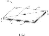
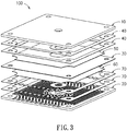
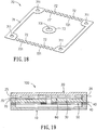
- the cell stack unit 100 includes an anode plate 10, a cathode plate 20, a cell unit 30, two sets of anode sealing materials 40, an anode metal net 50, a cathode metal net 60 and two sets of cathode sealing materials 70.
- the anode plate 10 formed as a rectangular plate has a first flow channel 14 structured on the top surface thereof, four first fuel input holes 11 located respectively to four corners thereof, and a first fuel output hole 12 located at the center thereof surrounded by the four first fuel input holes 11.
- the first fuel input holes 11 and the first fuel output hole 12 are all through holes communicating both sides of the anode plate 10.
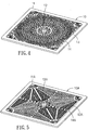
- the first flow channel 14 is structured with a plurality of first bumps 13 on the top surface of anode plate 10 in FIG.4 , where the plurality of first bumps 13 are arranged to encircle the first fuel output hole 12.
- the plurality of first bumps 13 are arranged symmetrically along circles with different radiuses to the center point of the first fuel output hole 12.
- the anode plate 10A has four first fuel input holes 11A, a first fuel output hole 12A, a plurality of first bumps 13A and a first flow channel 14A.
- the anode plate 10B has four first fuel input holes 11B, a first fuel output hole 12B, a plurality of first bumps 13B and a first flow channel 14B.
- the anode plate 10C has four first fuel input holes 11C, a first fuel output hole 12C, a plurality of first bumps 13C and a first flow channel 14C.
- the anode plate 10D has four first fuel input holes 11D, a first fuel output hole 12D, a plurality of first bumps 13D and a first flow channel 14D.
- the anode plate 10E has four first fuel input holes 11E, a first fuel output hole 12E, a plurality of first bumps 13E and a first flow channel 14E.
- the anode plate 10F has four first fuel input holes 11F, a first fuel output hole 12F, a plurality of first bumps 13F and a first flow channel 14F.
- the major difference between any of the anode plates 10A ⁇ 10F of FIG.5 ⁇ FIG.10 and the anode plate 10 of FIG.4 is the difference of the arrangement and the formation of the first bumps 13 ⁇ 13F. Nevertheless, no matter what kind of the arrangement and the formation of the first bumps is, all these first bumps 13, 13A ⁇ 13F are all surrounding the first fuel output hole 12 ⁇ 12F in a symmetrical manner. Upon such an arrangement, the flow field on the anode plate 10 ⁇ 10F can be evenly distributed.
- any of the anode plates 10 ⁇ 10F of FIG.4 ⁇ FIG.10 is rectangular shaped with the four first fuel input holes 11 ⁇ 11F located to the four corners, and with the fuel output holes 12 ⁇ 12F at the center thereof, such that the arrangement of the first bumps 13 ⁇ 13F in accordance with the symmetrical manner can be easily provided.
- the anode plate is other shaped, then the fuel input holes and the fuel output hole shall be embodied in a pattern other than any of FIG.4 ⁇ FIG.10 .
- the formation of the first bumps shall not be limited to that in any of FIG.4 ⁇ FIG.10 .
- any formation of the first bumps can be a candidate if and only if the formation of the bumps can achieve the goal of an even-distributed flow field.
- part of the first bumps 13 can be treated as supportive nodes for enhancing the structural strength and for bifurcating and disturbing the flow in the first flow channel 14 ⁇ 14F.
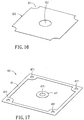
- the cathode plate 20 shaped as a rectangle has a second flow channel 24 structured on the top surface thereof, four second fuel input holes 21 located at respective corners thereof and a second fuel output hole 22 located at the center thereof.
- the plurality of second fuel input holes 21 are to surround the second fuel output hole 22, and the second fuel input holes 21 and the second fuel output hole 22 are all through holes for communicating both sides of the cathode plate 20.
- the second flow channel 24 is configured by a plurality of second bumps 23, in which the plurality of second bumps 23 are arranged to encircle the second fuel output hole 22.
- the plurality of second bumps 23 are arranged symmetrically along circles with different radiuses to the center point of the second fuel output hole 22.
- a plurality of second air input grooves 25 are disposed, while a plurality of second air output grooves 26 are disposed along the opposing lateral side thereof.
- the second air input grooves 25, the second air output grooves 26 and the second flow channel 24 are all communicative in space.
- the second bumps 23 include various shapes of bumps, such as a plurality of parallel longitudinal strips extending in a direction parallel to the second air input grooves 25 and the second air output grooves 26, such that the air can smoothly flow from the second air input grooves 25, through the second flow channel 24, and finally to the second air output grooves 26.
- the cathode plate 20A has four second fuel input holes 21A, a second fuel output hole 22A, a plurality of second bumps 23A, a second flow channel 24A, a plurality of second air input grooves 25A and a plurality of second air output grooves 26A.
- the cathode plate 20B has four second fuel input holes 21B, a second fuel output hole 22B, a plurality of second bumps 23B, a second flow channel 24B, a plurality of second air input grooves 25A and a plurality of second air output grooves 26A.
- the major difference between any of the cathode plates 20A ⁇ 10B of FIG.12 ⁇ FIG.13 and the cathode plate 20 of FIG. 11 is the difference of the arrangement and the formation of the second bumps 23 ⁇ 23F. Nevertheless, no matter what kind of the arrangement and the formation of the second bumps is, all these second bumps 23 ⁇ 23B are all surrounding the second fuel output hole 22 ⁇ 22A in a symmetrical manner including parallel longitudinal strip or island structures. In particular, the extending direction of these island structures are parallel to that of the second air input grooves 25A, 25B and the second air output grooves 26A, 26B. Upon such an arrangement, the flow field on the cathode plate 20 ⁇ 20B can be evenly distributed.
- the cathode plates 20 ⁇ 20B are rectangular shaped, the four second fuel input holes 21 ⁇ 21B are located to respective corners, the second fuel output holes 22 ⁇ 22B are centrally located, the second air input grooves 25 ⁇ 25B, and the second air output grooves 26 ⁇ 26B are parallel extending.
- the second bumps 23 ⁇ 23B are symmetrically arranged and in a longitudinal island structures. Namely, if the cathode plate is other shaped, then the fuel input holes, the fuel output hole, the air input grooves and the air output grooves shall be embodied in a pattern other than any of FIG.11 ⁇ FIG. 13 .
- the formation of the second bumps shall not be limited to that in any of FIG.11 ⁇ FIG.13 .
- part of the second bumps 23 can be treated as supportive nodes for enhancing the structural strength and for bifurcating and disturbing the flow in the second flow channel 24 ⁇ 24B.
- the material for the anode plates 10 ⁇ 10F of FIG.4 ⁇ FIG.10 and the cathode plates 20 ⁇ 20B of FIG.11 ⁇ FIG.13 can be one of a high temperature alloy and an electric conductive material, such as a high nickel alloy, a stainless steel 441, a Crofer 22 and so on.
- the cell unit 30 formed as a rectangle has four third fuel input holes 31 located at respective corners thereof and a third fuel output hole 32 located at the center thereof.
- the plurality of third fuel input holes 31 are to surround the third fuel output hole 32, and the third fuel input holes 31 and the third fuel output hole 32 are all through holes for communicating both sides of the cell unit 30.
- Two opposing sides of the cell unit 30 are disposed with a cathode layer 33 and an anode layer 34, respectively.
- An electrolyte layer 35 is disposed between the cathode layer 33 and the anode layer 34.
- the anode plate 10 is mounted onto the cell unit 30 at the side having the anode layer 34 in a manner of the first flow channel 14 facing the anode layer 34.
- the cathode plate 20 is mounted onto the cell unit 30 at the side having the cathode layer 33 in a manner of the second flow channel 24 facing the cathode layer 33.
- the cell unit 30 is mainly to fit a generation system, and thus the shape thereof is not limited to the aforesaid rectangle. If the cell unit 30 is other shaped, shapes of the anode plate 10 ⁇ 10F of FIG.4 ⁇ FIG.10 and the cathode plate 20 ⁇ 20B of FIG.11 ⁇ FIG.13 are varied accordingly.
- the cell unit 30 can be an anode-supported planar SOFC or an electrolyte-supported planar SOFC.
- the cell unit 30 can have (but not limited to) a size of 10.8cm ⁇ 10.8cm.
- the anode metal net 50 formed as a rectangle to be mounted onto the anode layer 34 of the cell unit 30 has four cutouts 51 at respective corners thereof and a hole 52 at the center thereof.
- the hole 52 is to avoid possible installation interference between the anode metal net 50 and the anode sealing material 40.
- candidate shape for the anode metal net 50 is not limited to the shape shown in the illustrated embodiment, but is to satisfy the criterion that is able to contact the anode layer 34 of the cell unit 30 without influencing the inflow and outflow of the fuel.
- the cathode metal net 60 formed as a rectangle to be mounted onto the cathode layer 33 of the cell unit 30 has four cutouts 61 at respective corners thereof and a hole 62 at the center thereof.
- the hole 62 is to avoid possible installation interference between the cathode metal net 60 and the cathode sealing material 70.
- candidate shape for the cathode metal net 60 is not limited to the shape shown in the illustrated embodiment, but is to satisfy the criterion that is able to contact the cathode layer 33 of the cell unit 30 without influencing the inflow and outflow of the fuel.
- the anode sealing material 40 disposed between the anode plate 10 and the cell unit 30 is consisted of a rectangular frame portion 41 and a circular portion 42.
- the rectangular frame portion 41 has four corners to dispose fourth respective fuel input holes 411.
- a fourth fuel output hole 421 is disposed at the center of the circular portion 42.
- the cathode sealing material 70 disposed between the cathode plate 20 and the cell unit 30 is consisted of two longitudinal portions 71, a plurality of rectangular portions 72 and a circular portion 73, in which the two longitudinal portions 71 and the plurality of rectangular portions 72 are integrated to form a hollow rectangular frame having four corners disposed with respective seventh fuel input holes 711. Between every two neighboring rectangular portions, a passage 721 is formed. A seventh fuel output hole 731 is disposed at the center of the circular portion 73.
- the anode sealing material 40 and the cathode sealing material 70 are to serve an air-tight purpose for the engagement of the anode plate 10, the cell unit 30 and the cathode plate 20 so as to be insulated from the anode metal net 50 and the cathode metal net 60.
- the anode sealing material 40 and the cathode sealing material 70 can be made of a ceramic material, a mixed material of ceramics and glass, or a proper insulation material such as Al 2 O 3 or SiO 2 -B 2 O 3 -Al 2 O 3- BaO glass-ceramics.
- shapes of the anode sealing material 40 and cathode sealing material 70 are not limited to the illustrated embodiments.
- an acceptable shape should meet the characteristics of surrounding the first fuel input holes 11, the first fuel output hole 12, the first flow channel 13, the cell unit 30 and the anode metal net 50, not to interference inflow and outflow of the fuel, sealing tightly the anode plate 10 and the cell unit 30, and insulating the anode metal net 50.
- an acceptable shape should meet the characteristics of surrounding the second fuel input holes 21, the second fuel output hole 22, the second flow channel 24, the cell unit 30 and the cathode metal net 60, not to interference the input and output of the air and the fuel, sealing tightly the cathode plate 20 and the cell unit 30, and insulating the cathode metal net 60.
- FIG.2 and FIG.3 two sets of the anode sealing material 40 and two sets of the cathode sealing material 70 are included.
- the application of the anode sealing material 40 and the cathode sealing material 70 are various in shapes and numbers, but meet the practical needs.
- the anode plate 10, the anode sealing material 40, the anode metal net 50, the cell unit 30, the cathode metal net 60, the cathode sealing material 70 and the cathode plate 20 are laminated in order, in which the first fuel input holes 11, the fourth fuel input holes 411, the third fuel input holes 31, the seventh fuel input holes 711, and the second fuel input holes 21 should be aligned in positions, and also the first fuel output hole 12, the fourth fuel output hole 421, the third fuel output hole 32, the seventh fuel output hole 731, and the second fuel output hole 22 shall be aligned in positions (referred also to FIG.2 .
- the air flows in the cell stack unit 100 via the second air input grooves 25, through cathode metal net 60, and out of the cell stack unit 100 via the second air output grooves 26 (as the dash-arrowed path).
- the fuel can flow in the cell stack unit 100 via the first fuel input holes 11, through the anode metal net 50, and leave the cell stack unit 100 via the first fuel output hole 12 (as the solid-arrowed path).
- the material for the seal material 27 is not limited to a specific one, and can adopt the same material for the cathode plate 20, a metal or ceramics with a sealing material for inhibiting leak of the fuel.
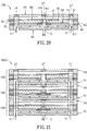
- the cell stack module 100A is produced by stacking a plurality the cell stack units 100 of FIG.1 in a laminating manner. Each of the cell stack units 100 is piled by having the anode plate 10 as the bottom to top the cathode plate 20 of a lower cell stack unit 100.
- the seal material 27 is disposed into the second fuel input holes 21 and the second fuel output hole 22 of the top cathode plate 20 so as to all the fuel input holes and the fuel output holes of the cell stack module 100A to be communicative in space.
- the fuel enters each of the cell stack units 100 from the respective first fuel input holes 11, flows through the respective anode metal nets 50, and then leave the cell stack module 100A via the first fuel output hole 12 at the bottom of the cell stack module 100A (as the solid-arrowed path).
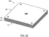
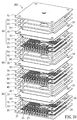
- the cell stack module 200 includes an anode plate 10, a cathode plate 20, a plurality of connection plates 80 and a plurality of cell sets 90. In this embodiment with three cell sets 90, two connection plates 80 are required to separate the cells. It is noted that the anode plate 10 and the cathode plate 20 are structured as the same as the corresponding anode plate 10 and cathode plate 20 of FIG.2 .
- connection plate 80 shaped as a rectangle has four eighth fuel input holes 81 located at respective corners thereof and an eighth fuel output hole 82 located at the center thereof.
- the plurality of eighth fuel input holes 81 are to surround the eighth fuel output hole 32, and the eighth fuel input holes 81 and the eighth fuel output hole 82 are all through holes for communicating both sides of the connection plate 80.
- Two opposing sides of the connection plate 80 are defined as an anode flow channel area 83 and a cathode flow channel area 84, respectively.
- the anode flow channel area 83 is disposed with a plurality of anode bumps 831, where the plurality of anode bumps 831 encircle the eighth fuel output hole 82 in a manner of being arranged symmetrically along circles with different radiuses to the center point of the eighth fuel output hole 82.
- a plurality of cathode bumps 841 are disposed, where the plurality of cathode bumps 841 encircle the eighth fuel output hole 82 in a manner of being arranged symmetrically along circles with different radiuses to the center point of the eighth fuel output hole 82.
- connection plate 80 At a lateral side of the connection plate 80 on the surface defining the cathode flow channel area 84, a plurality of parallel eighth air input grooves 85 are constructed. At the other lateral side on the same surface of the connection plate 80, a plurality of parallel eighth air output grooves 86 are constructed by opposing to the eighth air input grooves 85.
- the eighth air input grooves 85, the eighth air output grooves 86 and the cathode flow channel area 84 are all communicative in space.
- the cathode bumps 841 may be various formed, including a plurality of parallel longitudinal island structures extending parallel to the eighth air input grooves 8 and the eighth air output grooves 86.
- the cathode flow channel area 84 can be embodied as that of the cathode plate 20.
- the connection plate 80 can be one of a high temperature alloy and an electric conductive material, such as a high nickel alloy, a stainless steel 441, a Crofer 22 and so on.
- the anode flow channel area 83 can be structured by resembling to the first flow channel 14 of the anode plate 10.
- the cathode flow channel area 84 can be structured by resembling to the second flow channel 24 of the cathode plate 20.
- the cell set 90 includes a cell unit 30, two anode sealing materials 40, an anode metal net 50, a cathode metal net 60 and two cathode sealing materials 70.
- the cell unit 30, the anode sealing material 40, the anode metal net 50, the cathode metal net 60 and the cathode sealing material 70 of this embodiment can be engineered by resembling to the cell unit 30, the anode sealing material 40, the anode metal net 50, the cathode metal net 60 and the cathode sealing material 70 of FIG.2 .
- the lower cell set 90 is disposed between the anode plate 10 and the lower connection plate 80.
- the anode sealing material 40 of the cell set 90 is mounted to surround the first fuel input holes 11, the first fuel output hole 12, the first flow channel 14, the cell unit 30 and the anode metal net 50.
- the cathode sealing material 70 of the cell set 90 is mounted to surround the eighth fuel input holes 81, the eighth fuel output hole 82, the cathode flow channel area 84, the cell unit 30 and the cathode metal net 60.
- the upper cell set 90 is disposed between the cathode plate 20 and the upper connection plate 80.
- the anode sealing material 40 of the cell set 90 is mounted to surround the eighth fuel input holes 81, the eighth fuel output hole 82, the anode flow channel area 83, the cell unit 30 and the anode metal net 50.
- the cathode sealing material 70 of the cell set 90 is mounted to surround the second fuel input holes 21, the second fuel output hole 22, the second flow channel 24, the cell unit 30 and the cathode metal net 60.
- the third cell set 90 of this embodiment is disposed between the two connection plates 80.
- the anode sealing material 40 of the cell set 90 is mounted to surround the eighth fuel input holes 81, the eighth fuel output hole 82, the anode flow channel area 83, the cell unit 30 and the anode metal net 50.
- the cathode sealing material 70 of the cell set 90 is mounted to surround the eighth fuel input holes 81, the eighth fuel output hole 82, the cathode flow channel area 84, the cell unit 30 and the cathode metal net 60.
- Each the anode layer 34 of the cell unit 30 is to face the anode plate 10 at the surface having the first flow channel 14, while each the cathode layer of the cell unit 30 is to face the cathode plate 20 at the surface having the second flow channel 24.
- the first fuel input holes 11, the second fuel input holes 21, the third fuel input holes 31 and the eighth fuel input holes 81 are aligned, respectively.
- the first fuel output hole 12, the second fuel output hole 22, the third fuel output hole 32 and the eighth fuel output hole 82 are aligned as well.
- the second air input holes 25 and the eighth air input holes 85 are aligned in position, while the second air output hole 26 and the eighth air output hole 86 are aligned, respectively.
- the second fuel input holes 21 and second fuel output hole 22 should be disposed with corresponding seal materials (not shown in the figure), and the fuel enters the cell stack module 200 via the first fuel input holes 11, then flows through every anode layer 34 of the corresponding cell unit 30, and finally leaves the cell stack module 200 via the first fuel output hole 12.
- the piling of three flat plate type solid oxide fuel cell stack units 100 of FIG.1 can also produce an apparatus resembling functionally to the flat plate type solid oxide fuel cell stack module 200 of FIG.22 .
- the thickness of the apparatus of FIG.21 would be larger.
- the connection plate 80 exists to replace the anode plate 10 and the neighboring cathode plate 20 of FIG.21 , such that the thickness of the flat plate type solid oxide fuel cell stack module 200 of FIG.22 can be substantially reduced.
- a protective layer shall be coated onto the surfaces of the cathode plate 20 and the cathode flow channel area 84 of the connection plate 80.
- Such a protective layer can be produced by screen-printing or plasma spraying a mixture of LSM, MnCo and perovskite so as to inhibit the vaporization of the Cr.
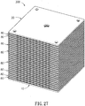
- FIG.27 a multi-unit cell stack module 300 is shown.
- Basic structuring for the cell stack module 300 is the same as that for the cell stack module 200 of FIG.22 .
- the cell stack module 300 includes one anode plate 10 as the bottom, one cathode plate 20 as the top, a plurality of the connection plates 80 and a plurality of the cell sets separated by the connection plates 80. From the descriptions of FIG.22 and FIG.27 , it is understood that, if the cell units 30 has a number N, then the number for the connection plates 80 would be N-1. Therefore, the embodiment of FIG.22 is disposed with three cell units 30 and two connection plates 80, and the embodiment of FIG.27 is disposed with 30 cell units 30 and 29 connection plates 80.
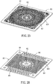
- the thickness of the anode plate 10 may be about 3 ⁇ 5mm, that of the cathode plate 20 may be about ⁇ 5mm, and that of the connection plate 80 may be about 2 ⁇ 3mm. Then, for the cell stack module of FIG.25 , the optimal performance contributed by coherent individual stack performance can be obtained at a loading of 20-50kg and an average stress of about 0.083 ⁇ 0.208kg/cm 2 .
- the fuel input holes are all to surround the fuel output hole.
- the reason for that is based on the consideration of even distribution of the incoming fuel.
- these two kinds of holes can be switched over in positions.
- the fuel output holes can be arranged to surround the fuel input hole.
- the flat plate type solid oxide fuel cell stack unit and the flat plate type solid oxide fuel cell stack module in accordance with the present invention are provided with advantages in a minimized volume, high efficiency, easy packing and assembling and can easily and modularly vary the stack arrangement so as to meet the specification needs of a generation system, Further, for the fuel input and output holes are all planar, so the objects in assembling, moving, loading and packing can be easily achieved. Also, while in application, the number of the cell units for stacking is not limited specifically, even that an optimal performance is demanded.
Landscapes
- Engineering & Computer Science (AREA)
- Manufacturing & Machinery (AREA)
- Life Sciences & Earth Sciences (AREA)
- Sustainable Development (AREA)
- Sustainable Energy (AREA)
- Chemical & Material Sciences (AREA)
- Chemical Kinetics & Catalysis (AREA)
- Electrochemistry (AREA)
- General Chemical & Material Sciences (AREA)
- Fuel Cell (AREA)
Claims (15)
- Festoxid - Brennstoffzellenstapeleinheit (100) des Flachplattentyps, umfassend:eine Anodenplatte (10), welche rechteckig ausgebildet ist und einen ersten Strömungskanal (14) aufweist, der an einer Oberfläche davon strukturiert ist, wobei an deren vier Ecken entsprechend vier erste Brennstoffeingangsöffnungen (11) angeordnet sind, und wobei in deren Mitte eine erste Brennstoffausgangsöffnung (12) angeordnet ist,eine Kathodenplatte (20), welche rechteckig geformt ist und einen zweiten Strömungskanal (24) aufweist, der an einer Oberfläche davon strukturiert ist, wobei an deren Ecken entsprechend vier zweite Brennstoffeingangsöffnungen (21) angeordnet sind, wobei in deren Mitte eine zweite Brennstoffausgangsöffnung (22) angeordnet ist, wobei eine Mehrzahl von zweiten Lufteingangsrillen (25) entlang einer lateralen Seite davon angeordnet ist, und wobei eine Mehrzahl von zweiten Luftausgangsrillen (26) entlang einer dieser lateralen Seite gegenüberliegenden anderen lateralen Seite davon angeordnet ist, wobei die zweiten Lufteingangsrillen (25), die zweiten Luftausgangsrillen (26) und der zweite Strömungskanal (24) räumlich alle miteinander in Verbindung stehen,eine Zelleneinheit (30), welche rechteckig geformt ist und vier dritte Brennstoffeingangsöffnungen (31) aufweist, die jeweils an deren Ecken angeordnet sind, wobei in deren Mitte eine dritte Brennstoffausgangsöffnung (32) angeordnet ist, wobei eine Kathodenschicht (33) an einer Seite davon vorgesehen ist, welche dem zweiten Strömungskanal (24) zugewandt ist, wobei eine Anodenschicht (34) an einer dieser Seite gegenüberliegenden anderen Seite davon vorgesehen ist und dem ersten Strömungskanal (14) zugewandt ist, wobei die vier ersten Brennstoffeingangsöffnungen (11), die vier zweiten Brennstoffeingangsöffnungen (21) und die vier dritten Brennstoffeingangsöffnungen (31) in den Positionen entsprechend ausgerichtet sind, wobei die erste Brennstoffausgangsöffnung (12), die zweite Brennstoffausgangsöffnung (22) und die dritte Brennstoffausgangsöffnung (32) entsprechend in den Positionen ausgerichtet sind,ein Anodenmetallnetz (50), das zwischen der Anodenplatte (10) und der Zelleneinheit (30) angeordnet ist,ein Kathodenmetallnetz (60), das zwischen der Kathodenplatte (20) und der Zelleneinheit (30) angeordnet ist,wenigstens ein Anodenabdichtmaterial (40), das zwischen der Anodenplatte (10) und der Zelleneinheit (30) vorgesehen ist, um die ersten Brennstoffeingangsöffnungen (11), die erste Brennstoffausgangsöffnung (12), den ersten Strömungskanal (14), die Zelleneinheit (30) und das Anodenmetallnetz (50) zu umschließen, undwenigstens ein Kathodenabdichtmaterial (70), das zwischen der Kathodenplatte (20) und der Zelleneinheit (30) vorgesehen ist, um die zweiten Brennstoffeingangsöffnungen (21), die zweite Brennstoffausgangsöffnung (22), den zweiten Strömungskanal (24), die Zelleneinheit (30) und das Kathodenmetallnetz (60) zu umschließen.
- Festoxid - Brennstoffzellenstapeleinheit (100) des Flachplattentyps nach Anspruch 1, bei welcher der erste Strömungskanal (14) mit einer Mehrzahl von ersten Erhebungen (13) versehen ist, wobei die Mehrzahl von ersten Erhebungen (13) so angeordnet ist, dass sie die erste Brennstoffausgaugsöffnung (12) entlang von Kreisen mit unterschiedlichen Radien in Bezug auf einen Mittelpunkt der ersten Brennstoffaüsgangsöffnung (12) symmetrisch umkreisen.
- Festoxid - Brennstoffzellenstapeleinheit (100) des Flachplattentyps nach Anspruch 1, bei welcher der zweite Strömungskanal (24) mit einer Mehrzahl von zweiten Erhebungen (23) versehen ist, wobei die Mehrzahl von zweiten Erhebungen (23) so angeordnet ist, dass sie die zweite Brennstoffausgangsöffnung (22) entlang von Kreisen mit unterschiedlichen Radien in Bezug auf einen Mittelpunkt der zweiten Brennstoffausgangsöffnung (22) symmetrisch umkreisen.
- Festoxid - Brennstoffzellenstapeleinheit (100) des Flachplattentyps nach Anspruch 3, bei welcher die zweite Erhebung (23) eine Mehrzahl von parallelen Längsstreifen umfasst, die sich in einer zu den zweiten Lufteingangsrillen (25) parallelen Richtung erstrecken.
- Festoxid - Brennstoffzellenstapeleinheit (100) des Flachplattentyps nach Anspruch 1, bei welcher ein Dichtungsmaterial (27) im Inneren von jeder der vier zweiten Brennstoffeingangsöffnungen (21) und der zweiten Brennstoffausgangsöffnung (22) vorgesehen ist.
- Festoxid - Brennstoffzellenstapelmodul (100A) des Flachplattentyps, welches eine Mehrzahl der Festoxid - Brennstoffzellenstapeleinheiten (100) des Flachplattentyps nach Anspruch 1 umfasst, wobei die Festoxid - Brennstoffzellenstapeleinheiten (100) des Flachplattentyps so gestapelt sind, dass die Anodenplatte (10) von einer oberen Festoxid - Brennstoffzellenstapeleinheit (100) des Flachplattentyps auf der Kathodenplatte (20) von einer unteren Festoxid - Brennstoffzellenstapeleinheit (100) des Flachplattentyps sitzt.
- Festoxid - Brennstoffzellenstapelmodul (100A) des Flachplattentyps nach Anspruch 6, bei welchem ein Dichtungsmaterial (27) im Inneren von jeder der vier zweiten Brennstoffeingangsöffnungen (21) und der zweiten Brennstoffausgangsöffnung (22) der obersten Kathodenplatte (20) vorgesehen ist.
- Festoxid - Brennstoffzellenstapelmodul (200) des Flachplattentyps, umfassend:eine Anodenplatte (10), die rechteckig geformt ist und einen ersten Strömungskanal (14) aufweist, der an einer Oberfläche davon strukturiert ist, wobei an deren vier Ecken entsprechend vier erste Brennstoffeingangsöffnungen (11) angeordnet sind, und wobei in deren Mitte eine erste Brennstoffausgangsöffnung (12) angeordnet ist,eine Kathodenplatte (20), die eine rechteckige Form hat und einen zweiten Strömungskanal (24) aufweist, der an einer Oberfläche davon strukturiert ist, wobei an deren Ecken entsprechend vier zweite Brennstoffeingangsöffnungen (21) angeordnet sind, wobei in deren Mitte eine zweite Brennstoffausgangsöffnung (22) angeordnet ist, wobei eine Mehrzahl von zweiten Lufteingangsrillen (25) entlang einer lateralen Seite davon angeordnet ist, und wobei eine Mehrzahl von zweiten Luftausgangsrillen (26) an der dieser lateralen Seite gegenüberliegenden anderen lateralen Seite davon vorgesehen ist, wobei die zweiten Lufteingangsrillen (25), die zweiten Luftausgangsrillen (26) und der zweite Strömungskanal (24) räumlich alle miteinander in Verbindung stehen,eine Mehrzahl von Verbindungsplatten (80), wobei jede der Verbindungsplatten eine rechteckige Form hat und vier entsprechen an deren Ecken angeordnete achte Brennstoffeingangsöffnungen (81), eine in deren Mitte angeordnete achte Brennstoffausgangsöffnung (82), einen an einer Seite davon vorgesehenen Anodenströmungskanalbereich (83), einen an der zu dieser lateralen Seite gegenüberliegenden anderen lateralen Seite angeordneten Kathodenströmungskanalbereich (84), eine Mehrzahl von achten Lufteingangsrillen (85), die entlang einer lateralen Seite von der den Kathodenströmungskanalbereich (84) aufweisenden Seite davon vorgesehen sind, und eine Mehrzahl von achten Luftausgangsrillen (86) aufweist, die an einer dieser lateralen Seite gegenüberliegenden anderen lateralen Seite davon vorgesehen ist, wobei die achten Lufteingangsrillen (85), die achten Luftausgangsrillen (86) und der Kathodenströmungskanalbereich (84) räumlich alle miteinander in Verbindung stehen, undeine Mehrzahl von Zellengruppen (90), wobei jede der Zellengruppen (90) umfasst:eine Zelleneinheit (30), die rechteckig geformt ist und vier dritte Brennstoffeingangsöffhungen (31), die entsprechend an deren Ecken angeordnet sind, eine in deren Mitte angeordnete dritte Brennstoffausgangsöffhung (32), eine an einer Seite davon angeordnete Kathodenschicht (33) und eine Anodenschicht (34) aufweist, die an der dieser Seite gegenüberliegenden anderen Seite davon angeordnet sind,ein Anodenmetallnetz (50), das zwischen der Anodenplatte (10) und der Zelleneinheit (30) angeordnet ist,ein Kathodenmetallnetz (60), das zwischen der Kathodenplatte (20) und der Zelleneinheit (30) angeordnet ist,wenigstens ein Anodenabdichtmaterial (40), das an derjenigen Seite der Zelleneinheit (30) vorgesehen ist, welche die Anodenschicht (34) aufweist, undwenigstens ein Kathodenabdichtmaterial (70), das an derjenigen Seite der Zelleneinheit (30) vorgesehen ist, welche die Kathodenschicht (33) aufweist,wobei eine der Zelleneinheiten (30) zwischen der Anodenplatte (10) und einer der Verbindungsplatten (80) angeordnet ist, wobei das Anodenabdichtmaterial (40) von dieser Zelleneinheit (30) zum Umschließen der korrespondierenden ersten Brennstoffeingangsöffnungen (11), der korrespondierenden ersten Brennstoffansgangsöffnung (12), des korrespondierenden ersten Strömungskanals (14), dieser Zelleneinheit (30) und des korrespondierenden Anodenmetallnetzes (50) dient, und wobei das Kathodenabdichtmaterial (70) von dieser Zelleneinheit (30) zum Umschließen der korrespondierenden achten Brennstoffeingangsöffnungen (81), der korrespondierenden achten Brennstoffausgangsöffnung (82), des korrespondierenden Kathodenströmungskanalbereichs (84), dieser Zelleneinheit (30) und des korrespondierenden Kathodenmetallnetzes (60) dient,wobei eine andere der Zelleneinheiten (30) zwischen der Kathodenplatte (20) und einer anderen der Verbindungsplatten (80) angeordnet ist, wobei das Anodenabdichtmaterial (40) von dieser Zelleneinheit (30) zum Umschließen der korrespondierenden achten Brennstoffeingangsöffnungen (81), der korrespondierenden achten Brennstoffausgangsöffnung (82), des korrespondierenden Anodenströmungskanalbereichs (83), dieser Zelleneinheit (30) und des korrespondierenden Anodenmetallnetzes (50) dient, und wobei das Kathodenabdichtmaterial (70) von dieser Zelleneinheit (30) zum Umschließen der korrespondierenden zweiten Brennstoffeingangsöffnungen (21), der korrespondierenden zweiten Brennstoffausgangsöffnung (22), des korrespondierenden zweiten Strömungskanals (24), dieser Zelleneinheit (30) und des korrespondierenden Kathodenmetallnetzes (60) dient, wobei eine der Zelleneinheiten (30) zwischen zwei benachbarten Verbindungsplatten (80) angeordnet ist, wobei das Anodenabdichtmaterial (40) von dieser Zelleneinheit (30) zum Umschließen der korrespondierenden achten Breunstoffeingangsöffnungen (81), der korrespondierenden achten Brennstoffausgangsöffnung (82), des korrespondierenden Anodenströmungskanalbereichs (83), dieser Zelleneinheit (30) und des korrespondierenden Anodenmetallnetzes (50) dient, und wobei das Kathodenabdichtmaterial (70) von dieser Zelleneinheit (30) zum Umschließen der korrespondierenden achten Brennstoffeingangsöffnungen (81), der korrespondierenden achten Brennstoffausgangsöffnung (82), des korrespondierenden Kathodenströmungskanalbereichs (84), dieser Zelleneinheit (30) und des korrespondierenden Kathodenmetallnetzes (60) dient,wobei die Anodenschicht (34) von jeder der Zelleneinheiten (30) dem ersten Strömungskanal (14) der korrespondierenden Anodenplatte (10) zugewandt ist, und wobei die Kathodenschicht (33) von jeder der Zelleneinheiten. (30) dem zweiten Strömungskanal (24) der korrespondierenden Kathodenplatte (20) zugewandt ist,wobei die ersten Brennstoffeingangsöffnungen (11), die zweiten Brennstoffeingangsöffnungen (21), die Mehrzahl von dritten Brennstoffeingangsöffnungen (31) und die Mehrzahl von achten Brennstoffeingangsöffnungen (81) entsprechend in den Positionen ausgerichtet sind, wobei die ersten Brennstoffausgangsöffnungen (12), die zweiten Brennstoffausgangsöffnungen (22), die dritten Brennstoffausgangsöffnungen (32) und die achten Brennstoffausgangsöffnungen (82) entsprechend in den Positionen ausgerichtet sind, wobei die zweiten Lufteingangsrillen (25) und die achten Lufteingangsrillen (85) entsprechend in den Positionen ausgerichtet sind, und wobei die zweiten Luftausgangsrillen (86) und die achten Luftausgangsrillen (86) entsprechend in den Positionen ausgerichtet sind.
- Festoxid - Brennstoffzellenstapelmodul (200) des Flachplattentyps nach Anspruch 8, bei welchem der Anodenströmungskanalbereich (83) mit einer Mehrzahl von Anodenerhebungen (831) versehen ist, wobei die Mehrzahl von Anodenerhebungen (831) so angeordnet ist, dass sie die achte Brennstoffausgangsöffnung (82) entlang von Kreisen mit unterschiedlichen Radien in Bezug auf einen Mittelpunkt der achten Brennstoffausgangsöffnung (82) symmetrisch umkreisen, wobei der Kathodenströmungskanalbereich (84) mit einer Mehrzahl von Kathodenerhebungen (841) versehen ist, wobei die Mehrzahl von Kathodenerhebungen (841) so angeordnet ist, dass sie die achte Brennstoffausgangsöffnung (82) entlang von Kreisen mit unterschiedlichen Radien in Bezug auf einen Mittelpunkt der achten Brennstoffausgangsöffnung (82) symmetrisch umkreisen.
- Festoxid - Brennstoffzellenstapelmodul (200) des Flachplattentyps nach Anspruch 8, bei welchem der erste Strömungskanal (14) mit einer Mehrzahl von ersten Erhebungen (13) versehen ist, wobei die Mehrzahl von ersten Erhebungen (13) so angeordnet ist, dass sie die erste Brennstoffausgangsöffnung (12) entlang von Kreisen mit unterschiedlichen Radien in Bezug auf einen Mittelpunkt der ersten Brennstoffausgangsöffnung (12) symmetrisch umkreisen.
- Festoxid - Brennstoffzellenstapelmodul (200) des Flachplattentyps nach Anspruch 10, bei welchem der Anodenströmungskanalbereich (83) gleich strukturiert ist wie der erste Strömungskanal (14).
- Festoxid - Brennstoffzellenstapelmodul (200) des Flachplattentyps nach Anspruch 8, bei welchem der zweite Strömungskanal (24) mit einer Mehrzahl von zweiten Erhebungen (23) versehen ist, wobei die Mehrzahl von zweiten Erhebungen (23) so angeordnet ist, dass sie die zweite Brennstoffausgangsöffnung (22) entlang von Kreisen mit unterschiedlichen Radien in Bezug auf einen Mittelpunkt der zweiten Brennstoffausgangsöffnung (22) symmetrisch umkreisen.
- Festoxid - Brennstoffzellenstapelmodul (200) des Flachplattentyps nach Anspruch 12, bei welchem die zweite Erhebung (23) eine Mehrzahl von parallelen Längsstreifen umfasst, die sich in einer zu den zweiten Lufteingangsrillen (25) parallelen Richtung erstrecken.
- Festoxid - Brennstoffzellenstapelmodul (200) des Flachplattentyps nach Anspruch 13, bei welchem der Kathodenströmungskanalbereich (44) gleich strukturiert ist wie der zweite Strömungskanal (24).
- Festoxid - Brennstoffzellenstapelmodul (200) des Flachplattentyps nach Anspruch 8, bei welchem ein Dichtungsmaterial (27) im Inneren von jeder der vier zweiten Brennstoffeingangsöffnungen (21) und der zweiten Brennstoffausgangsöffnung (22) vorgesehen ist.
Applications Claiming Priority (1)
| Application Number | Priority Date | Filing Date | Title |
|---|---|---|---|
| TW103135990A TWI513090B (zh) | 2014-10-17 | 2014-10-17 | 平板型固態氧化物燃料電池堆單元及平板型固態氧化物燃料電池堆模組 |
Publications (2)
| Publication Number | Publication Date |
|---|---|
| EP3010076A1 EP3010076A1 (de) | 2016-04-20 |
| EP3010076B1 true EP3010076B1 (de) | 2017-08-16 |
Family
ID=52394152
Family Applications (1)
| Application Number | Title | Priority Date | Filing Date |
|---|---|---|---|
| EP15152175.4A Not-in-force EP3010076B1 (de) | 2014-10-17 | 2015-01-22 | Flachplattentyp-festoxid-brennstoffzellenstapel und flachplattentyp-festoxidbrennstoffzellenstapelmodul |
Country Status (3)
| Country | Link |
|---|---|
| US (1) | US10218013B2 (de) |
| EP (1) | EP3010076B1 (de) |
| TW (1) | TWI513090B (de) |
Families Citing this family (12)
| Publication number | Priority date | Publication date | Assignee | Title |
|---|---|---|---|---|
| US10170786B1 (en) | 2016-12-22 | 2019-01-01 | National Taipei University Of Technology | Modular planar interconnect device for a solid oxide fuel cell and the solid oxide fuel cell containing the same |
| US10170773B2 (en) | 2016-12-22 | 2019-01-01 | National Taipei University Of Technology | Modular planar interconnect device for a solid oxide fuel cell and the solid oxide fuel cell containing the same |
| CN106784957B (zh) * | 2016-12-23 | 2019-04-30 | 宁波索福人能源技术有限公司 | 一种燃料电池堆和固定块之间密封导电结构 |
| CN108365242A (zh) * | 2018-02-09 | 2018-08-03 | 东莞深圳清华大学研究院创新中心 | 一种固体氧化物燃料电池 |
| TWI708955B (zh) * | 2018-10-19 | 2020-11-01 | 行政院原子能委員會核能研究所 | 固態氧化物電解電池測試及產氫裝置 |
| CN109509895A (zh) * | 2018-12-20 | 2019-03-22 | 中国地质大学(武汉) | 一种固体氧化物燃料电池 |
| CN109830732B (zh) * | 2019-01-25 | 2024-08-13 | 哈尔滨工业大学(深圳) | 一种不对称平板型结构高温固态燃料电池的电堆结构 |
| GB201917650D0 (en) | 2019-12-03 | 2020-01-15 | Ceres Ip Co Ltd | Cell unit and cell stack |
| CN111048810B (zh) * | 2019-12-25 | 2021-04-23 | 武汉理工氢电科技有限公司 | 一种燃料电池膜电极的生产方法 |
| CN115360378A (zh) * | 2022-05-25 | 2022-11-18 | 徐州华清京昆能源有限公司 | 一种具有防爆燃保险的固体氧化物燃料电堆 |
| CN114933010B (zh) * | 2022-07-08 | 2025-04-29 | 西安交通大学 | 一种基于赋形燃料电池组件的机翼动力一体化装置 |
| CN118136909B (zh) * | 2024-05-08 | 2024-08-23 | 西安稀有金属材料研究院有限公司 | 固体氧化物燃料电池电堆及其制备方法、能源系统 |
Family Cites Families (10)
| Publication number | Priority date | Publication date | Assignee | Title |
|---|---|---|---|---|
| JPH10125338A (ja) * | 1996-10-22 | 1998-05-15 | Fuji Electric Co Ltd | 固体高分子電解質型燃料電池 |
| US5851689A (en) * | 1997-01-23 | 1998-12-22 | Bechtel Corporation | Method for operating a fuel cell assembly |
| US6051330A (en) * | 1998-01-15 | 2000-04-18 | International Business Machines Corporation | Solid oxide fuel cell having vias and a composite interconnect |
| JP2003157865A (ja) * | 2001-11-19 | 2003-05-30 | Honda Motor Co Ltd | 燃料電池スタック |
| JP2007335353A (ja) * | 2006-06-19 | 2007-12-27 | Toyota Motor Corp | 燃料電池 |
| JP2009245632A (ja) * | 2008-03-28 | 2009-10-22 | Mitsubishi Materials Corp | 平板型の固体酸化物形燃料電池 |
| AU2009345159A1 (en) * | 2009-04-30 | 2011-11-17 | Fdi Energy, Inc. | High-volume-manufacture fuel cell arrangement and method for production thereof |
| US8968956B2 (en) * | 2010-09-20 | 2015-03-03 | Nextech Materials, Ltd | Fuel cell repeat unit and fuel cell stack |
| JP5684664B2 (ja) * | 2011-07-13 | 2015-03-18 | 本田技研工業株式会社 | 燃料電池スタック |
| JP6214279B2 (ja) * | 2012-09-21 | 2017-10-18 | 住友精密工業株式会社 | 燃料電池 |
-
2014
- 2014-10-17 TW TW103135990A patent/TWI513090B/zh active
-
2015
- 2015-01-02 US US14/588,483 patent/US10218013B2/en active Active
- 2015-01-22 EP EP15152175.4A patent/EP3010076B1/de not_active Not-in-force
Non-Patent Citations (1)
| Title |
|---|
| None * |
Also Published As
| Publication number | Publication date |
|---|---|
| US10218013B2 (en) | 2019-02-26 |
| TWI513090B (zh) | 2015-12-11 |
| US20160111738A1 (en) | 2016-04-21 |
| TW201616715A (zh) | 2016-05-01 |
| EP3010076A1 (de) | 2016-04-20 |
Similar Documents
| Publication | Publication Date | Title |
|---|---|---|
| US10218013B2 (en) | Flat plate type solid oxide fuel cell stack unit and flat plate type solid oxide fuel cell stack module | |
| US8968956B2 (en) | Fuel cell repeat unit and fuel cell stack | |
| JP5227543B2 (ja) | 燃料電池 | |
| US10008732B2 (en) | Solid oxide fuel cell stack | |
| JP5261440B2 (ja) | 燃料電池スタック | |
| EP3279989B1 (de) | Brennstoffzelle vom flachplattentyp | |
| CA2472138A1 (en) | End structure of a fuel cell stack | |
| WO2008021102A3 (en) | Fuel cell for use in a portable fuel cell system | |
| US10693153B2 (en) | Interconnector-electrochemical reaction unit cell composite body, electrochemical reaction cell stack, and method of manufacturing interconnector-electrochemical reaction unit cell composite body | |
| GB2492509A (en) | Thermal management in a fuel cell stack | |
| JP5502615B2 (ja) | 燃料電池 | |
| US20190036146A1 (en) | Flat plate type fuel cell | |
| US20180183072A1 (en) | Solid oxide fuel cell | |
| CN108110300B (zh) | 固体氧化物燃料电池电堆及为其分配气体的气流分配板 | |
| US7645537B2 (en) | Multi-cell fuel cell layer and system | |
| US11936075B2 (en) | Separator for solid oxide fuel cell (SOFC) stack capable of minimizing system volume and usage of sealant | |
| JP2010165629A (ja) | 固体電解質形燃料電池 | |
| JP3791702B2 (ja) | 平板状固体電解質燃料電池 | |
| JPH10312818A (ja) | 固体電解質型燃料電池 | |
| KR20200079670A (ko) | 스택 내부의 열분포가 개선된 연료전지 | |
| KR100808028B1 (ko) | 단전지들이 평면 배열된 등가의 대면적 연료전지 및 이에사용되는 압축형 밀봉재 | |
| JP6024930B2 (ja) | 固体電解質形燃料電池 | |
| KR20160007830A (ko) | 스택 부피의 최소화가 가능한 입체 구조 고체산화물 연료전지 및 그 제조방법 | |
| ATE537575T1 (de) | Festoxid-brennstoffzellenrahmen und herstellungsverfahren | |
| JP6517600B2 (ja) | 燃料電池スタック |
Legal Events
| Date | Code | Title | Description |
|---|---|---|---|
| PUAI | Public reference made under article 153(3) epc to a published international application that has entered the european phase |
Free format text: ORIGINAL CODE: 0009012 |
|
| 17P | Request for examination filed |
Effective date: 20150622 |
|
| AK | Designated contracting states |
Kind code of ref document: A1 Designated state(s): AL AT BE BG CH CY CZ DE DK EE ES FI FR GB GR HR HU IE IS IT LI LT LU LV MC MK MT NL NO PL PT RO RS SE SI SK SM TR |
|
| AX | Request for extension of the european patent |
Extension state: BA ME |
|
| RBV | Designated contracting states (corrected) |
Designated state(s): AL AT BE BG CH CY CZ DE DK EE ES FI FR GB GR HR HU IE IS IT LI LT LU LV MC MK MT NL NO PL PT RO RS SE SI SK SM TR |
|
| GRAP | Despatch of communication of intention to grant a patent |
Free format text: ORIGINAL CODE: EPIDOSNIGR1 |
|
| RIC1 | Information provided on ipc code assigned before grant |
Ipc: H01M 8/1246 20160101ALI20170206BHEP Ipc: H01M 8/00 20160101AFI20170206BHEP Ipc: H01M 8/0273 20160101ALI20170206BHEP Ipc: H01M 8/2432 20160101ALI20170206BHEP Ipc: H01M 8/2483 20160101ALI20170206BHEP Ipc: H01M 8/0263 20160101ALI20170206BHEP |
|
| INTG | Intention to grant announced |
Effective date: 20170221 |
|
| GRAS | Grant fee paid |
Free format text: ORIGINAL CODE: EPIDOSNIGR3 |
|
| GRAA | (expected) grant |
Free format text: ORIGINAL CODE: 0009210 |
|
| AK | Designated contracting states |
Kind code of ref document: B1 Designated state(s): AL AT BE BG CH CY CZ DE DK EE ES FI FR GB GR HR HU IE IS IT LI LT LU LV MC MK MT NL NO PL PT RO RS SE SI SK SM TR |
|
| REG | Reference to a national code |
Ref country code: GB Ref legal event code: FG4D |
|
| REG | Reference to a national code |
Ref country code: CH Ref legal event code: EP |
|
| REG | Reference to a national code |
Ref country code: IE Ref legal event code: FG4D |
|
| REG | Reference to a national code |
Ref country code: AT Ref legal event code: REF Ref document number: 919896 Country of ref document: AT Kind code of ref document: T Effective date: 20170915 |
|
| REG | Reference to a national code |
Ref country code: DE Ref legal event code: R096 Ref document number: 602015004071 Country of ref document: DE |
|
| REG | Reference to a national code |
Ref country code: DE Ref legal event code: R082 Ref document number: 602015004071 Country of ref document: DE Representative=s name: NEGENDANCK, MATTHIAS, DIPL.-PHYS. UNIV. DR.-IN, DE |
|
| REG | Reference to a national code |
Ref country code: NL Ref legal event code: MP Effective date: 20170816 |
|
| REG | Reference to a national code |
Ref country code: LT Ref legal event code: MG4D |
|
| REG | Reference to a national code |
Ref country code: AT Ref legal event code: MK05 Ref document number: 919896 Country of ref document: AT Kind code of ref document: T Effective date: 20170816 |
|
| REG | Reference to a national code |
Ref country code: FR Ref legal event code: PLFP Year of fee payment: 4 |
|
| PG25 | Lapsed in a contracting state [announced via postgrant information from national office to epo] |
Ref country code: AT Free format text: LAPSE BECAUSE OF FAILURE TO SUBMIT A TRANSLATION OF THE DESCRIPTION OR TO PAY THE FEE WITHIN THE PRESCRIBED TIME-LIMIT Effective date: 20170816 Ref country code: NL Free format text: LAPSE BECAUSE OF FAILURE TO SUBMIT A TRANSLATION OF THE DESCRIPTION OR TO PAY THE FEE WITHIN THE PRESCRIBED TIME-LIMIT Effective date: 20170816 Ref country code: FI Free format text: LAPSE BECAUSE OF FAILURE TO SUBMIT A TRANSLATION OF THE DESCRIPTION OR TO PAY THE FEE WITHIN THE PRESCRIBED TIME-LIMIT Effective date: 20170816 Ref country code: SE Free format text: LAPSE BECAUSE OF FAILURE TO SUBMIT A TRANSLATION OF THE DESCRIPTION OR TO PAY THE FEE WITHIN THE PRESCRIBED TIME-LIMIT Effective date: 20170816 Ref country code: LT Free format text: LAPSE BECAUSE OF FAILURE TO SUBMIT A TRANSLATION OF THE DESCRIPTION OR TO PAY THE FEE WITHIN THE PRESCRIBED TIME-LIMIT Effective date: 20170816 Ref country code: NO Free format text: LAPSE BECAUSE OF FAILURE TO SUBMIT A TRANSLATION OF THE DESCRIPTION OR TO PAY THE FEE WITHIN THE PRESCRIBED TIME-LIMIT Effective date: 20171116 |
|
| PG25 | Lapsed in a contracting state [announced via postgrant information from national office to epo] |
Ref country code: GR Free format text: LAPSE BECAUSE OF FAILURE TO SUBMIT A TRANSLATION OF THE DESCRIPTION OR TO PAY THE FEE WITHIN THE PRESCRIBED TIME-LIMIT Effective date: 20171117 Ref country code: RS Free format text: LAPSE BECAUSE OF FAILURE TO SUBMIT A TRANSLATION OF THE DESCRIPTION OR TO PAY THE FEE WITHIN THE PRESCRIBED TIME-LIMIT Effective date: 20170816 Ref country code: LV Free format text: LAPSE BECAUSE OF FAILURE TO SUBMIT A TRANSLATION OF THE DESCRIPTION OR TO PAY THE FEE WITHIN THE PRESCRIBED TIME-LIMIT Effective date: 20170816 Ref country code: IS Free format text: LAPSE BECAUSE OF FAILURE TO SUBMIT A TRANSLATION OF THE DESCRIPTION OR TO PAY THE FEE WITHIN THE PRESCRIBED TIME-LIMIT Effective date: 20171216 Ref country code: PL Free format text: LAPSE BECAUSE OF FAILURE TO SUBMIT A TRANSLATION OF THE DESCRIPTION OR TO PAY THE FEE WITHIN THE PRESCRIBED TIME-LIMIT Effective date: 20170816 Ref country code: BG Free format text: LAPSE BECAUSE OF FAILURE TO SUBMIT A TRANSLATION OF THE DESCRIPTION OR TO PAY THE FEE WITHIN THE PRESCRIBED TIME-LIMIT Effective date: 20171116 Ref country code: ES Free format text: LAPSE BECAUSE OF FAILURE TO SUBMIT A TRANSLATION OF THE DESCRIPTION OR TO PAY THE FEE WITHIN THE PRESCRIBED TIME-LIMIT Effective date: 20170816 |
|
| PG25 | Lapsed in a contracting state [announced via postgrant information from national office to epo] |
Ref country code: CZ Free format text: LAPSE BECAUSE OF FAILURE TO SUBMIT A TRANSLATION OF THE DESCRIPTION OR TO PAY THE FEE WITHIN THE PRESCRIBED TIME-LIMIT Effective date: 20170816 Ref country code: DK Free format text: LAPSE BECAUSE OF FAILURE TO SUBMIT A TRANSLATION OF THE DESCRIPTION OR TO PAY THE FEE WITHIN THE PRESCRIBED TIME-LIMIT Effective date: 20170816 Ref country code: RO Free format text: LAPSE BECAUSE OF FAILURE TO SUBMIT A TRANSLATION OF THE DESCRIPTION OR TO PAY THE FEE WITHIN THE PRESCRIBED TIME-LIMIT Effective date: 20170816 |
|
| REG | Reference to a national code |
Ref country code: DE Ref legal event code: R097 Ref document number: 602015004071 Country of ref document: DE |
|
| PG25 | Lapsed in a contracting state [announced via postgrant information from national office to epo] |
Ref country code: SK Free format text: LAPSE BECAUSE OF FAILURE TO SUBMIT A TRANSLATION OF THE DESCRIPTION OR TO PAY THE FEE WITHIN THE PRESCRIBED TIME-LIMIT Effective date: 20170816 Ref country code: IT Free format text: LAPSE BECAUSE OF FAILURE TO SUBMIT A TRANSLATION OF THE DESCRIPTION OR TO PAY THE FEE WITHIN THE PRESCRIBED TIME-LIMIT Effective date: 20170816 Ref country code: EE Free format text: LAPSE BECAUSE OF FAILURE TO SUBMIT A TRANSLATION OF THE DESCRIPTION OR TO PAY THE FEE WITHIN THE PRESCRIBED TIME-LIMIT Effective date: 20170816 Ref country code: SM Free format text: LAPSE BECAUSE OF FAILURE TO SUBMIT A TRANSLATION OF THE DESCRIPTION OR TO PAY THE FEE WITHIN THE PRESCRIBED TIME-LIMIT Effective date: 20170816 |
|
| PLBE | No opposition filed within time limit |
Free format text: ORIGINAL CODE: 0009261 |
|
| STAA | Information on the status of an ep patent application or granted ep patent |
Free format text: STATUS: NO OPPOSITION FILED WITHIN TIME LIMIT |
|
| 26N | No opposition filed |
Effective date: 20180517 |
|
| PG25 | Lapsed in a contracting state [announced via postgrant information from national office to epo] |
Ref country code: SI Free format text: LAPSE BECAUSE OF FAILURE TO SUBMIT A TRANSLATION OF THE DESCRIPTION OR TO PAY THE FEE WITHIN THE PRESCRIBED TIME-LIMIT Effective date: 20170816 |
|
| REG | Reference to a national code |
Ref country code: CH Ref legal event code: PL |
|
| PG25 | Lapsed in a contracting state [announced via postgrant information from national office to epo] |
Ref country code: LU Free format text: LAPSE BECAUSE OF NON-PAYMENT OF DUE FEES Effective date: 20180122 |
|
| REG | Reference to a national code |
Ref country code: IE Ref legal event code: MM4A |
|
| REG | Reference to a national code |
Ref country code: BE Ref legal event code: MM Effective date: 20180131 |
|
| PG25 | Lapsed in a contracting state [announced via postgrant information from national office to epo] |
Ref country code: CH Free format text: LAPSE BECAUSE OF NON-PAYMENT OF DUE FEES Effective date: 20180131 Ref country code: LI Free format text: LAPSE BECAUSE OF NON-PAYMENT OF DUE FEES Effective date: 20180131 Ref country code: BE Free format text: LAPSE BECAUSE OF NON-PAYMENT OF DUE FEES Effective date: 20180131 |
|
| PG25 | Lapsed in a contracting state [announced via postgrant information from national office to epo] |
Ref country code: IE Free format text: LAPSE BECAUSE OF NON-PAYMENT OF DUE FEES Effective date: 20180122 |
|
| PG25 | Lapsed in a contracting state [announced via postgrant information from national office to epo] |
Ref country code: MC Free format text: LAPSE BECAUSE OF FAILURE TO SUBMIT A TRANSLATION OF THE DESCRIPTION OR TO PAY THE FEE WITHIN THE PRESCRIBED TIME-LIMIT Effective date: 20170816 |
|
| PG25 | Lapsed in a contracting state [announced via postgrant information from national office to epo] |
Ref country code: MT Free format text: LAPSE BECAUSE OF NON-PAYMENT OF DUE FEES Effective date: 20180122 |
|
| PG25 | Lapsed in a contracting state [announced via postgrant information from national office to epo] |
Ref country code: TR Free format text: LAPSE BECAUSE OF FAILURE TO SUBMIT A TRANSLATION OF THE DESCRIPTION OR TO PAY THE FEE WITHIN THE PRESCRIBED TIME-LIMIT Effective date: 20170816 |
|
| PG25 | Lapsed in a contracting state [announced via postgrant information from national office to epo] |
Ref country code: PT Free format text: LAPSE BECAUSE OF FAILURE TO SUBMIT A TRANSLATION OF THE DESCRIPTION OR TO PAY THE FEE WITHIN THE PRESCRIBED TIME-LIMIT Effective date: 20170816 |
|
| PG25 | Lapsed in a contracting state [announced via postgrant information from national office to epo] |
Ref country code: HU Free format text: LAPSE BECAUSE OF FAILURE TO SUBMIT A TRANSLATION OF THE DESCRIPTION OR TO PAY THE FEE WITHIN THE PRESCRIBED TIME-LIMIT; INVALID AB INITIO Effective date: 20150122 Ref country code: CY Free format text: LAPSE BECAUSE OF FAILURE TO SUBMIT A TRANSLATION OF THE DESCRIPTION OR TO PAY THE FEE WITHIN THE PRESCRIBED TIME-LIMIT Effective date: 20170816 Ref country code: MK Free format text: LAPSE BECAUSE OF NON-PAYMENT OF DUE FEES Effective date: 20170816 Ref country code: HR Free format text: LAPSE BECAUSE OF FAILURE TO SUBMIT A TRANSLATION OF THE DESCRIPTION OR TO PAY THE FEE WITHIN THE PRESCRIBED TIME-LIMIT Effective date: 20170816 |
|
| PG25 | Lapsed in a contracting state [announced via postgrant information from national office to epo] |
Ref country code: AL Free format text: LAPSE BECAUSE OF FAILURE TO SUBMIT A TRANSLATION OF THE DESCRIPTION OR TO PAY THE FEE WITHIN THE PRESCRIBED TIME-LIMIT Effective date: 20170816 |
|
| PGFP | Annual fee paid to national office [announced via postgrant information from national office to epo] |
Ref country code: GB Payment date: 20220119 Year of fee payment: 8 Ref country code: DE Payment date: 20211104 Year of fee payment: 8 |
|
| PGFP | Annual fee paid to national office [announced via postgrant information from national office to epo] |
Ref country code: FR Payment date: 20220119 Year of fee payment: 8 |
|
| REG | Reference to a national code |
Ref country code: DE Ref legal event code: R119 Ref document number: 602015004071 Country of ref document: DE |
|
| GBPC | Gb: european patent ceased through non-payment of renewal fee |
Effective date: 20230122 |
|
| PG25 | Lapsed in a contracting state [announced via postgrant information from national office to epo] |
Ref country code: GB Free format text: LAPSE BECAUSE OF NON-PAYMENT OF DUE FEES Effective date: 20230122 Ref country code: DE Free format text: LAPSE BECAUSE OF NON-PAYMENT OF DUE FEES Effective date: 20230801 |
|
| PG25 | Lapsed in a contracting state [announced via postgrant information from national office to epo] |
Ref country code: FR Free format text: LAPSE BECAUSE OF NON-PAYMENT OF DUE FEES Effective date: 20230131 |