EP3009585A1 - Kraftfahrzeugschloss - Google Patents
Kraftfahrzeugschloss Download PDFInfo
- Publication number
- EP3009585A1 EP3009585A1 EP15179085.4A EP15179085A EP3009585A1 EP 3009585 A1 EP3009585 A1 EP 3009585A1 EP 15179085 A EP15179085 A EP 15179085A EP 3009585 A1 EP3009585 A1 EP 3009585A1
- Authority
- EP
- European Patent Office
- Prior art keywords
- lock
- latch
- motor vehicle
- braking
- lock latch
- Prior art date
- Legal status (The legal status is an assumption and is not a legal conclusion. Google has not performed a legal analysis and makes no representation as to the accuracy of the status listed.)
- Granted
Links
Images


Classifications
-
- E—FIXED CONSTRUCTIONS
- E05—LOCKS; KEYS; WINDOW OR DOOR FITTINGS; SAFES
- E05B—LOCKS; ACCESSORIES THEREFOR; HANDCUFFS
- E05B85/00—Details of vehicle locks not provided for in groups E05B77/00 - E05B83/00
- E05B85/20—Bolts or detents
- E05B85/24—Bolts rotating about an axis
- E05B85/243—Bolts rotating about an axis with a bifurcated bolt
-
- E—FIXED CONSTRUCTIONS
- E05—LOCKS; KEYS; WINDOW OR DOOR FITTINGS; SAFES
- E05B—LOCKS; ACCESSORIES THEREFOR; HANDCUFFS
- E05B77/00—Vehicle locks characterised by special functions or purposes
- E05B77/36—Noise prevention; Anti-rattling means
- E05B77/38—Cushion elements, elastic guiding elements or holding elements, e.g. for cushioning or damping the impact of the bolt against the striker during closing of the wing
-
- E—FIXED CONSTRUCTIONS
- E05—LOCKS; KEYS; WINDOW OR DOOR FITTINGS; SAFES
- E05B—LOCKS; ACCESSORIES THEREFOR; HANDCUFFS
- E05B79/00—Mounting or connecting vehicle locks or parts thereof
- E05B79/10—Connections between movable lock parts
-
- E—FIXED CONSTRUCTIONS
- E05—LOCKS; KEYS; WINDOW OR DOOR FITTINGS; SAFES
- E05B—LOCKS; ACCESSORIES THEREFOR; HANDCUFFS
- E05B85/00—Details of vehicle locks not provided for in groups E05B77/00 - E05B83/00
- E05B85/04—Strikers
- E05B85/045—Strikers for bifurcated bolts
-
- E—FIXED CONSTRUCTIONS
- E05—LOCKS; KEYS; WINDOW OR DOOR FITTINGS; SAFES
- E05B—LOCKS; ACCESSORIES THEREFOR; HANDCUFFS
- E05B77/00—Vehicle locks characterised by special functions or purposes
- E05B77/36—Noise prevention; Anti-rattling means
- E05B77/40—Lock elements covered by silencing layers, e.g. coatings
-
- E—FIXED CONSTRUCTIONS
- E05—LOCKS; KEYS; WINDOW OR DOOR FITTINGS; SAFES
- E05B—LOCKS; ACCESSORIES THEREFOR; HANDCUFFS
- E05B85/00—Details of vehicle locks not provided for in groups E05B77/00 - E05B83/00
- E05B85/20—Bolts or detents
- E05B85/24—Bolts rotating about an axis
- E05B85/26—Cooperation between bolts and detents
Definitions
- the invention is directed at a motor vehicle lock according to claim 1.
- the motor vehicle lock in question can in particular be assigned to a motor vehicle door.
- the expression "motor vehicle door” is to be understood in a broad sense. It includes in particular side doors, back doors, lift gates, trunk lids or engine hoods. Such a motor vehicle door may generally be designed as a sliding door as well.
- the lock latch In such a motor vehicle lock in the closed position, the lock latch is in a holding engagement with the lock striker. In such a state, the lock latch is pre-stressed in the opening direction, that is in a direction of movement to release the lock striker. Even though this pre-stress, generally stemming from a dedicated spring and/or from sealing of the associated door, is usually quite high, the pawl is in an engagement position with the lock latch in that state and exerts a blocking force by means of a blocking engagement on the lock latch, thereby preventing movement of the lock latch in the opening direction. Thus, the lock latch remains in holding engagement with the lock striker.
- the lock latch is moved in the closing direction, generally until it reaches the main latching position.
- an end stop is provided.
- a substantial overlifting i.e. a movement of the lock latch beyond the main latching position.
- an end stop is provided.
- the invention is based on the realization that, for motor vehicle locks with a lock striker bracket, i.e. a lock striker arrangement comprising two bars moving relative to the lock latch, a braking arrangement with a contact surface can be provided for, which exerts a contact force acting between the lock latch and the frame bar - i.e. that lock striker bar not received by the lock latch, as opposed to the latch bar which is received by the lock latch.
- This contact force provides a braking force against movement of the latch.
- the invention makes use of a component of the lock striker which has hitherto been neglected for the opening and closing operation of the motor vehicle lock, namely that part of the lock striker not received by the lock latch.
- the force which needs to be exerted by the pawl in order to hold the lock latch in the main latching position can be reduced, thereby "relieving" the pawl to a certain extent. Further, it becomes possible not only to reduce the noise caused e.g. by the deflection of the pawl in the release position, but also to affect different frequencies of the noise in a specific manner based on the properties of the braking arrangement.
- the above braking force may at least partly or even substantially be a frictional force according to the preferred embodiment of claim 2. It may as well at least partly or even substantially be a vector component of the contact force, which vector component acts against movement of the lock latch.
- Claims 4 and 5 are directed at preferred embodiments in which during the closing cycle or the opening cycle of the motor vehicle lock, respectively, there is a gliding movement across the contact surface. When there is friction, each such movement has to traverse a path acting against that friction. The absorption of the impact energy during the closing cycle or the release of the spring in the opening cycle is protracted at least throughout the time for this traversal.
- the preferred embodiment of claim 6 provides for different regions of the contact surface being configured to exert different levels of braking forces. Thereby, a specific desired braking behavior may be provided for by the contact surface.
- a part of the contact surface may have a protrusion which exerts an even greater braking force acting against the movement of the lock latch.
- a braking arrangement exerting a braking force that acts on the frame bar may also obviate the need for a separate structure against overlifting, as is described by the preferred embodiment of claim 8.
- claims 9 and 10 are directed at a braking element configured to be compressed for exerting a restoring force, which restoring force may then contribute to the contact force and as a result to the braking force.
- the preferred embodiment of claim 11 provides for having at least part of the flux of force of the retaining force exerted on the latch bar being closed through the frame bar.
- the braking arrangement can be arranged either on the side of the lock latch, on the side or the frame bar or even independently of either structure.
- the preferred embodiments of claims 12 and 13 are directed at having the braking arrangement arranged on the side of the lock latch and the preferred embodiments of claims 14 and 15 are directed at having the braking arrangement arranged on the side of the frame bar.
- the motor vehicle locks 1 shown in the drawings are each assigned to a motor vehicle door (not shown). Regarding the broad interpretation of the expression "motor vehicle door”, reference is made to the introductory part of the specification. Here and preferably the motor vehicle door is a side door of the motor vehicle.
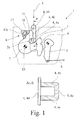
- the motor vehicle lock 1 comprises the usual locking elements lock latch 2, pawl 3 - which pawl 3 is assigned to the lock latch 2 - and a lock striker bracket 4 comprising a latch bar 4a and a frame bar 4b.
- the lock striker bracket 4 also comprises a transverse bar 4c fixedly coupling the latch bar 4a and the frame bar 4b, which transverse bar 4c is shown in Fig. 1 only.
- the latch bar 4a and the frame bar 4b are connected to a base plate 4d also shown in Fig. 1 .
- the latch bar 4a, the frame bar 4b and the transverse bar are preferably of one piece.
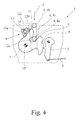
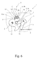
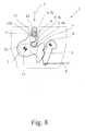
- the lock latch 2 can be brought into an open position ( Fig. 1 , 4 and 7 ) and into at least one latching position, which for the present embodiments comprises a preliminary latching position ( Fig. 2 , 5 and 8 ) and a main latching position ( Fig. 3 , 6 and 9 ).
- the lock latch 2 when in one of the latching positions ( Fig. 2 , 3 , 5 , 6 , 8 , 9 ), is or may be brought into holding engagement with the latch bar 4a.
- the latch bar 4a is or may be positioned in an inlet opening 2a of the lock latch 2, while the frame bar 4b stays outside the inlet opening 2a.
- a closing cycle of the motor vehicle lock 1 is initiated by the latch bar 4a coming into engagement with the lock latch 2 when the motor vehicle door is being closed by the user ( Fig. 1 , 4 and 7 ).
- the direction of travel of the latch bar 4a is denoted by reference number 5 in the drawings. It may be taken from this that during a closing cycle the frame bar 4b follows the latch bar 4a.
- the above noted closing cycle of the motor vehicle lock 1 comprises moving the lock latch 2 from the open position ( Fig. 1 , 4 and 7 ) to the at least one latching position - for the present embodiments the main latching position ( Fig. 3 , 6 and 9 ) -, wherein the pawl 3 may fall into at least one engagement position, in which it is in blocking engagement with a preliminary latching detent 6 or a main latching detent 7.
- the movement to the main latching position occurs via the preliminary latching position ( Fig. 2 , 5 and 8 ).
- the engagement between the pawl 3 and the preliminary latching detent 6 or the main latching detent 7 leads to blocking the lock latch 2 in its preliminary latching position or in its main latching position, respectively.
- the pawl 3 may be deflected into at least one release position ( Fig. 1 , 4 and 7 ), in which it releases the lock latch 2.
- a pawl actuation apparatus 8 for performing such a deflection movement, a pawl actuation apparatus 8, in particular a paw1 actuation lever - which is not shown for the present embodiments - may be provided.
- the motor vehicle lock 1 further comprises a braking arrangement 9 arranged such that a contact surface 10 of the braking arrangement 9 can be brought into a braking engagement with a counterpart 11 such that a contact force exerted by the contact surface 10 provides a braking force against movement of the lock latch 2.
- the counterpart 11 can in principle be any surface with which the contact surface 10 can be brought into engagement, examples of which will be described in further detail below.
- the above contact force provides a braking force against movement of the lock latch 2 relative to the position of the braking engagement of the contact surface 10 with the counterpart 11.
- the movement of the lock latch 2 is - as seen in the drawings - a rotational movement.
- the braking force may act against movement of the lock latch 2 in both of the directions of rotation of the lock latch 2 or against movement in only either one of the directions of rotation of the lock latch 2. Whether or not the braking force against movement in both directions or only against movement in one direction may also depend on the current position of the lock latch 2 and the relative position of the frame bar 4b to it.
- the motor vehicle lock 1 is characterized in that the braking force is acting between the lock latch 2 and the frame bar 4b.
- the braking force is in any case transmitted through the frame bar 4b.
- the contact surface 10 engages the frame bar 4b directly, though that may be the case as shown in Fig. 1 to 6 for the first and second embodiments. It may also be that the braking force is acting on the frame bar 4b indirectly. This is the case for example for the third embodiment of Fig. 7 to 9 .
- the braking force comprises a frictional force exerted by the contact surface 10 against the counterpart 11. This frictional force may be due to static friction or due to kinetic friction at different times.
- the contact surface 10 can be brought into the braking engagement 9 for one or more arbitrary positions of the lock latch 2. It is preferred that the braking arrangement 9 is arranged such that the contact surface 10 of the braking arrangement 9 is in a braking engagement when the lock latch 2 is in a frame bar engagement position, which in other words is a specific position of the lock latch 2. There may also be more than one such frame bar engagement position. Here, it is preferred that the frame bar engagement position is one of the latching positions.
- the braking arrangement 9 is arranged such that the contact surface 10 of the braking arrangement 9 is in a braking engagement when the lock latch 2 is in the preliminary latching position ( Fig. 2 , 5 and 8 ) or in the main latching position ( Fig. 3 , 6 and 9 ).
- the braking force acts against the lock latch 2 moving from the frame bar engagement position and in particular, that the braking force acts against the lock latch 2 moving toward the open position and/or opposite to the open position.
- This may also be different for different frame bar engagement positions.
- the magnitude of the braking force may be different for both directions.
- the engagement between the contact surface 10 and the counterpart 11 is such that the braking force substantially acts only against movement of the lock latch 2 opposite to the open position, i.e. in a closing direction.
- the braking arrangement 9 is arranged such that there is a closing gliding movement of the counterpart 11 across the contact surface 10 during a closing cycle in which the lock latch 2 is brought into holding engagement with the latch bar 4a.
- a closing gliding movement against the contact force providing the braking force leads to the absorption of energy.
- an opening cycle of the motor vehicle lock 1 comprises moving the lock latch 2 to the open position for releasing the latch bar 4a and that the braking arrangement 9 is arranged such that there is a opening gliding movement of the counterpart 11 across the contact surface 10 during the opening cycle.
- This is also realized for all embodiments shown here and substantially corresponds to a progression opposite to the closing cycle.
- the braking arrangement 9 and in particular the contact surface 10 may be formed and in particular shaped to achieve a specific desired behavior. For example, it may be desirable to have different braking forces, i.e. greater or smaller braking forces, acting against movement of the lock latch 2. Therefore, it is preferred that the contact surface 10 comprises a first region 12a configured to exert a first contact force when engaging the counterpart 11 and a second region 12b configured to exert a second contact force when engaging the counterpart 11 and that the second contact force is greater than the first contact force. In particular, this first contact force and second contact force, respectively, may be exerted during the closing gliding movement and/or the opening gliding movement.
- first region 12a and a second region 12b there are in principle many options for providing such a first region 12a and a second region 12b, for example by choosing specific and varying materials or coatings for the contact surface 10 or by providing for a particular geometry of the braking arrangement 9 or the contact surface 10. As seen in the second embodiment of Fig. 4 to 6 , it may be that the first region 12a comprises a substantially planar section and the second region 12b comprises a protruding section.
- the braking arrangement 9 may serve this purpose, thereby obviating the need for a separate stopping arrangement. Accordingly, it is preferred that the braking arrangement 9 is configured to block movement of the lock latch 2 beyond a limit position, in particular to block an overlifting of the lock latch 2, in a direction of movement of the closing cycle through the braking force. That limit position may in particular be one of the at least one latching position and in particular the main latching position. Note that for this blocking to occur it suffices that the braking force need only be sufficient to overcome a force acting on the lock latch 2 within reasonable limits, since here only a closing force exerted by a human being is relevant in practice.
- the braking arrangement 9 comprises an elastic braking element 13 configured to be compressed when the contact surface 10 is brought into the braking engagement with the counterpart 11.
- the contact force goes back on a restoring force of the elastic brake element 13 exerted by the contact surface 10 against the counterpart 11.
- this braking element 13 may be bounded by the contact surface 10, as can be seen in Fig. 1 to 9 for all three embodiments.
- the braking element 13 may surround an inner hollow space 13a, which may either be empty or filled with a different material different from that of the braking element 13.
- a protrusion of the contact surface 10 as described above is suitable for increasing both the frictional force and the restoring force in the section in which the protrusion is present.
- the braking force substantially is a vector component of the restoring force.
- the frictional force then only contributes a small portion to the braking force.
- the braking force is substantially determined by the frictional force, such that extensive dynamic effects like extensive vibration tendencies, that may go back on the elasticity of the elastic braking element 13, are prevented.
- the braking force may still comprise a restoring force component, but this restoring force component is then in any case smaller than the frictional force. It is to be noted that this respective preponderance of either the frictional force or the restoring force may be different for different positions of the lock latch 2, i.e. for different contact situations between the contact surface 10 and the counterpart 11.
- the spring characteristics, in particular the spring elasticity, associated with particular sections of the contact surface, in particular associated with particular sections of the elastic braking element 13, may be different.
- the contact surface 10 may comprise a section with a greater range of spring of the elastic braking element 13 and a section with a smaller range of spring of the elastic braking element 13.
- the above first region 12a may correspond to the section with the smaller range of spring and the above second region 12b may correspond to the section with the greater range of spring. It is to be pointed out that increasing the range of spring may not only affect the restoring force, but also the frictional force, even if the material properties of the braking element 13 remain the same otherwise.
- the contact surface 10 is configured such that the braking force for moving away from a particular position of the lock latch 2 is substantially maximized, i.e. not maximized in a strict mathematical sense but chosen as great as possible within reasonable and practical limits. This may apply for example to the main latching position, because for the main latching position an overlifting as described above is to be limited on the one hand and the initial movement in the opening direction is preferably slowed down to prevent e.g. annoying banging noise.
- a corresponding rest point 14 of engagement of the contact surface 10 with the counterpart 11 is such that the braking force against a movement out of this rest position of the lock latch 2 is substantially maximized.
- a corresponding rest point 14 of engagement of the contact surface 10 with the counterpart 11 has a locally minimal range of spring.
- the frame bar 4b is fixedly connected to the latch bar 4a and regularly made of a single piece with the latch bar 4a, it becomes possible to arrange for a closed flux of force through the lock striker bracket 4 with these components, the lock latch 2 and the braking arrangement 9.
- the contact force will generally be insufficient to obviate the need for the pawl 3 entirely, thereby not eliminating the force being transmitted through in particular a bearing 15 of the lock latch 2, at least that force can be reduced, which in turn results in less stress for components of the motor vehicle door supporting the motor vehicle lock 1 and in particular the lock latch 2.
- a flux of force of at least a part of a retaining force exerted by the lock latch 2 on the latch bar 4a is closed through the contact surface 10 and the frame bar 4b through the braking engagement.
- the braking arrangement 9 is fixedly arranged at the lock latch 2.
- the frame bar 4b comprises the counterpart 11. This corresponds to the first and second embodiments of Fig. 1 to 6 , respectively.
- the braking arrangement 9 is arranged at an edge of the lock latch 2 which moves into an inlet path of the latch bar 4a during the closing cycle of the motor vehicle lock 1.
- the braking arrangement 9 is fixedly arranged at the frame bar 4b.
- the lock latch 2 comprises the counterpart 11.
- the counterpart 11 is arranged at an edge of the lock latch 2 which moves into the inlet path of the latch bar 4a during the closing cycle of the motor vehicle lock 1.
- the lock latch 2 preferably comprises a metallic base body which is coated with a dampening material, which in turn is preferably a soft-elastic plastic material with good internal damping behavior, which here and in the following shall be referred to as a first material.
- This first material may be a plastic material, in particular a thermoplastic polyester elastomer (TPE-E).
- TPE-E thermoplastic polyester elastomer
- the commercially available products Hytrel 4774, Hytrel 5225 and Hytrel 6356 from DuPont or Riteflex 677 from Ticona have proven particularly advantageous in practice.
- the respective Shore hardness (ISO 868, 15s) are preferably between 43 and 77 and in particular at 51 (Hytrel 5526).
- the braking arrangement 9, and in particular the braking element 13 and the contact surface 10, may now be produced by having an appropriately greater extension of the dampening material, i.e. the first material.
- the braking element 13 and the contact surface 10 is comprised by a coating of the lock latch 2.
- the braking element 13 and in particular the contact surface 10 may be made from an overmould of a second material based on the lock latch 2 with the metallic base body and the coating with the first material, which second material may be identical or different from the above first material.
- the braking element 13 and the contact surface 10 may be attached to the coating of the lock latch 2 through another method.
Applications Claiming Priority (1)
| Application Number | Priority Date | Filing Date | Title |
|---|---|---|---|
| US201462065436P | 2014-10-17 | 2014-10-17 |
Publications (2)
| Publication Number | Publication Date |
|---|---|
| EP3009585A1 true EP3009585A1 (de) | 2016-04-20 |
| EP3009585B1 EP3009585B1 (de) | 2020-03-04 |
Family
ID=53765128
Family Applications (1)
| Application Number | Title | Priority Date | Filing Date |
|---|---|---|---|
| EP15179085.4A Active EP3009585B1 (de) | 2014-10-17 | 2015-07-30 | Kraftfahrzeugschloss |
Country Status (2)
| Country | Link |
|---|---|
| US (1) | US9593515B2 (de) |
| EP (1) | EP3009585B1 (de) |
Cited By (1)
| Publication number | Priority date | Publication date | Assignee | Title |
|---|---|---|---|---|
| WO2018196908A1 (de) * | 2017-04-26 | 2018-11-01 | Kiekert Ag | Schloss für ein kraftfahrzeug |
Families Citing this family (1)
| Publication number | Priority date | Publication date | Assignee | Title |
|---|---|---|---|---|
| US20240059197A1 (en) * | 2022-08-17 | 2024-02-22 | Kiekert Ag | Motor vehicle latch, in particular motor vehicle backrest latch |
Citations (6)
| Publication number | Priority date | Publication date | Assignee | Title |
|---|---|---|---|---|
| GB2192423A (en) * | 1986-07-11 | 1988-01-13 | Kiekert Gmbh Co Kg | Keeper for a motor vehicle door lock and its production |
| US4756564A (en) * | 1986-12-19 | 1988-07-12 | Kabushikikaisha Anseikogyo | Vehicle door latch |
| JP2003293638A (ja) * | 2002-04-04 | 2003-10-15 | Shiroki Corp | ロック装置 |
| DE10216313A1 (de) * | 2002-04-12 | 2003-10-23 | Bayerische Motoren Werke Ag | Drehfalle eines Schlosses mit einer Dämpfungsschicht |
| EP1516986A2 (de) * | 2003-09-19 | 2005-03-23 | ArvinMeritor Light Vehicle Systems (UK) Ltd | Fallenmechanismus |
| WO2010129683A1 (en) * | 2009-05-05 | 2010-11-11 | A. Raymond Et Cie. | Stricker with round antichuck bumper |
Family Cites Families (1)
| Publication number | Priority date | Publication date | Assignee | Title |
|---|---|---|---|---|
| DE202012011372U1 (de) | 2012-11-28 | 2014-03-05 | BROSE SCHLIEßSYSTEME GMBH & CO. KG | Kraftfahrzeugschloss |
-
2015
- 2015-07-30 EP EP15179085.4A patent/EP3009585B1/de active Active
- 2015-10-15 US US14/884,552 patent/US9593515B2/en active Active
Patent Citations (6)
| Publication number | Priority date | Publication date | Assignee | Title |
|---|---|---|---|---|
| GB2192423A (en) * | 1986-07-11 | 1988-01-13 | Kiekert Gmbh Co Kg | Keeper for a motor vehicle door lock and its production |
| US4756564A (en) * | 1986-12-19 | 1988-07-12 | Kabushikikaisha Anseikogyo | Vehicle door latch |
| JP2003293638A (ja) * | 2002-04-04 | 2003-10-15 | Shiroki Corp | ロック装置 |
| DE10216313A1 (de) * | 2002-04-12 | 2003-10-23 | Bayerische Motoren Werke Ag | Drehfalle eines Schlosses mit einer Dämpfungsschicht |
| EP1516986A2 (de) * | 2003-09-19 | 2005-03-23 | ArvinMeritor Light Vehicle Systems (UK) Ltd | Fallenmechanismus |
| WO2010129683A1 (en) * | 2009-05-05 | 2010-11-11 | A. Raymond Et Cie. | Stricker with round antichuck bumper |
Cited By (1)
| Publication number | Priority date | Publication date | Assignee | Title |
|---|---|---|---|---|
| WO2018196908A1 (de) * | 2017-04-26 | 2018-11-01 | Kiekert Ag | Schloss für ein kraftfahrzeug |
Also Published As
| Publication number | Publication date |
|---|---|
| US9593515B2 (en) | 2017-03-14 |
| EP3009585B1 (de) | 2020-03-04 |
| US20160108649A1 (en) | 2016-04-21 |
Similar Documents
| Publication | Publication Date | Title |
|---|---|---|
| AU2014211378B2 (en) | Multi-link hinge with damping | |
| US20020096405A1 (en) | Damping device for movable furniture parts | |
| US10724284B2 (en) | Appliance lid hinge assembly with snubber | |
| EP3009585B1 (de) | Kraftfahrzeugschloss | |
| KR20060129116A (ko) | 도어완충장치 및 이를 갖춘 가전제품 | |
| US20150020454A1 (en) | Foot-operated door opener, door and use | |
| EP2851495A2 (de) | Kraftfahrzeugschloss | |
| DE102011086736A1 (de) | Energieabsorbierender puffer für die schliessgeräuschgüte eines riegels | |
| EP2255055B1 (de) | Möbelscharnier | |
| KR20210080485A (ko) | 자동차 로크 | |
| KR101417664B1 (ko) | 자동차의 도어 힌지 장치 | |
| KR102258476B1 (ko) | 자동차용 도어 체커 | |
| EP2305929B1 (de) | Kraftfahrzeugschloss | |
| ITRM20060659A1 (it) | Maniglia per veicoli con dispositivo di sicurezza | |
| DE102013220335A1 (de) | Gepäckkoffer | |
| CN112900989A (zh) | 机动车门锁 | |
| DE102014214635A1 (de) | Haushaltskältegerät mit einem Schließnocken, der eine Koppelnase mit einer Mulde aufweist | |
| EP3153650B1 (de) | Dämpfungs- und verriegelungsvorrichtung für schiebetüren | |
| AU2015261474B2 (en) | Hinge for furniture or domestic appliances | |
| EP2205811A1 (de) | Verbesserungen bei bewegungssteuerungen | |
| KR101044842B1 (ko) | 충격완화 및 소음저감기능을 갖는 도어로크장치 | |
| CN210264209U (zh) | 静音全自动锁体斜舌及信号舌构造 | |
| KR101733631B1 (ko) | 가구용 가스 실린더 댐퍼 | |
| KR20080098863A (ko) | 뒤틀림 방지형 자동차용 도어체커 | |
| KR0138847Y1 (ko) | 차량용 도어핸들 댐핑장치 |
Legal Events
| Date | Code | Title | Description |
|---|---|---|---|
| PUAI | Public reference made under article 153(3) epc to a published international application that has entered the european phase |
Free format text: ORIGINAL CODE: 0009012 |
|
| AK | Designated contracting states |
Kind code of ref document: A1 Designated state(s): AL AT BE BG CH CY CZ DE DK EE ES FI FR GB GR HR HU IE IS IT LI LT LU LV MC MK MT NL NO PL PT RO RS SE SI SK SM TR |
|
| AX | Request for extension of the european patent |
Extension state: BA ME |
|
| RIN1 | Information on inventor provided before grant (corrected) |
Inventor name: ROSALES, DAVID Inventor name: WITTELSBUERGER, MICHAEL Inventor name: HANKE, STEPAN |
|
| 17P | Request for examination filed |
Effective date: 20161020 |
|
| RBV | Designated contracting states (corrected) |
Designated state(s): AL AT BE BG CH CY CZ DE DK EE ES FI FR GB GR HR HU IE IS IT LI LT LU LV MC MK MT NL NO PL PT RO RS SE SI SK SM TR |
|
| STAA | Information on the status of an ep patent application or granted ep patent |
Free format text: STATUS: EXAMINATION IS IN PROGRESS |
|
| 17Q | First examination report despatched |
Effective date: 20181023 |
|
| RIC1 | Information provided on ipc code assigned before grant |
Ipc: E05B 85/26 20140101ALN20190814BHEP Ipc: E05B 77/40 20140101ALN20190814BHEP Ipc: E05B 85/04 20140101ALI20190814BHEP Ipc: E05B 77/38 20140101AFI20190814BHEP |
|
| GRAP | Despatch of communication of intention to grant a patent |
Free format text: ORIGINAL CODE: EPIDOSNIGR1 |
|
| STAA | Information on the status of an ep patent application or granted ep patent |
Free format text: STATUS: GRANT OF PATENT IS INTENDED |
|
| INTG | Intention to grant announced |
Effective date: 20190930 |
|
| GRAS | Grant fee paid |
Free format text: ORIGINAL CODE: EPIDOSNIGR3 |
|
| GRAA | (expected) grant |
Free format text: ORIGINAL CODE: 0009210 |
|
| STAA | Information on the status of an ep patent application or granted ep patent |
Free format text: STATUS: THE PATENT HAS BEEN GRANTED |
|
| AK | Designated contracting states |
Kind code of ref document: B1 Designated state(s): AL AT BE BG CH CY CZ DE DK EE ES FI FR GB GR HR HU IE IS IT LI LT LU LV MC MK MT NL NO PL PT RO RS SE SI SK SM TR |
|
| REG | Reference to a national code |
Ref country code: GB Ref legal event code: FG4D |
|
| REG | Reference to a national code |
Ref country code: CH Ref legal event code: EP |
|
| REG | Reference to a national code |
Ref country code: AT Ref legal event code: REF Ref document number: 1240532 Country of ref document: AT Kind code of ref document: T Effective date: 20200315 |
|
| REG | Reference to a national code |
Ref country code: DE Ref legal event code: R096 Ref document number: 602015048044 Country of ref document: DE |
|
| REG | Reference to a national code |
Ref country code: IE Ref legal event code: FG4D |
|
| PG25 | Lapsed in a contracting state [announced via postgrant information from national office to epo] |
Ref country code: FI Free format text: LAPSE BECAUSE OF FAILURE TO SUBMIT A TRANSLATION OF THE DESCRIPTION OR TO PAY THE FEE WITHIN THE PRESCRIBED TIME-LIMIT Effective date: 20200304 Ref country code: RS Free format text: LAPSE BECAUSE OF FAILURE TO SUBMIT A TRANSLATION OF THE DESCRIPTION OR TO PAY THE FEE WITHIN THE PRESCRIBED TIME-LIMIT Effective date: 20200304 Ref country code: NO Free format text: LAPSE BECAUSE OF FAILURE TO SUBMIT A TRANSLATION OF THE DESCRIPTION OR TO PAY THE FEE WITHIN THE PRESCRIBED TIME-LIMIT Effective date: 20200604 |
|
| REG | Reference to a national code |
Ref country code: NL Ref legal event code: MP Effective date: 20200304 |
|
| PG25 | Lapsed in a contracting state [announced via postgrant information from national office to epo] |
Ref country code: GR Free format text: LAPSE BECAUSE OF FAILURE TO SUBMIT A TRANSLATION OF THE DESCRIPTION OR TO PAY THE FEE WITHIN THE PRESCRIBED TIME-LIMIT Effective date: 20200605 Ref country code: BG Free format text: LAPSE BECAUSE OF FAILURE TO SUBMIT A TRANSLATION OF THE DESCRIPTION OR TO PAY THE FEE WITHIN THE PRESCRIBED TIME-LIMIT Effective date: 20200604 Ref country code: HR Free format text: LAPSE BECAUSE OF FAILURE TO SUBMIT A TRANSLATION OF THE DESCRIPTION OR TO PAY THE FEE WITHIN THE PRESCRIBED TIME-LIMIT Effective date: 20200304 Ref country code: LV Free format text: LAPSE BECAUSE OF FAILURE TO SUBMIT A TRANSLATION OF THE DESCRIPTION OR TO PAY THE FEE WITHIN THE PRESCRIBED TIME-LIMIT Effective date: 20200304 Ref country code: SE Free format text: LAPSE BECAUSE OF FAILURE TO SUBMIT A TRANSLATION OF THE DESCRIPTION OR TO PAY THE FEE WITHIN THE PRESCRIBED TIME-LIMIT Effective date: 20200304 |
|
| REG | Reference to a national code |
Ref country code: LT Ref legal event code: MG4D |
|
| PG25 | Lapsed in a contracting state [announced via postgrant information from national office to epo] |
Ref country code: NL Free format text: LAPSE BECAUSE OF FAILURE TO SUBMIT A TRANSLATION OF THE DESCRIPTION OR TO PAY THE FEE WITHIN THE PRESCRIBED TIME-LIMIT Effective date: 20200304 |
|
| PG25 | Lapsed in a contracting state [announced via postgrant information from national office to epo] |
Ref country code: ES Free format text: LAPSE BECAUSE OF FAILURE TO SUBMIT A TRANSLATION OF THE DESCRIPTION OR TO PAY THE FEE WITHIN THE PRESCRIBED TIME-LIMIT Effective date: 20200304 Ref country code: CZ Free format text: LAPSE BECAUSE OF FAILURE TO SUBMIT A TRANSLATION OF THE DESCRIPTION OR TO PAY THE FEE WITHIN THE PRESCRIBED TIME-LIMIT Effective date: 20200304 Ref country code: IS Free format text: LAPSE BECAUSE OF FAILURE TO SUBMIT A TRANSLATION OF THE DESCRIPTION OR TO PAY THE FEE WITHIN THE PRESCRIBED TIME-LIMIT Effective date: 20200704 Ref country code: SK Free format text: LAPSE BECAUSE OF FAILURE TO SUBMIT A TRANSLATION OF THE DESCRIPTION OR TO PAY THE FEE WITHIN THE PRESCRIBED TIME-LIMIT Effective date: 20200304 Ref country code: LT Free format text: LAPSE BECAUSE OF FAILURE TO SUBMIT A TRANSLATION OF THE DESCRIPTION OR TO PAY THE FEE WITHIN THE PRESCRIBED TIME-LIMIT Effective date: 20200304 Ref country code: RO Free format text: LAPSE BECAUSE OF FAILURE TO SUBMIT A TRANSLATION OF THE DESCRIPTION OR TO PAY THE FEE WITHIN THE PRESCRIBED TIME-LIMIT Effective date: 20200304 Ref country code: SM Free format text: LAPSE BECAUSE OF FAILURE TO SUBMIT A TRANSLATION OF THE DESCRIPTION OR TO PAY THE FEE WITHIN THE PRESCRIBED TIME-LIMIT Effective date: 20200304 Ref country code: PT Free format text: LAPSE BECAUSE OF FAILURE TO SUBMIT A TRANSLATION OF THE DESCRIPTION OR TO PAY THE FEE WITHIN THE PRESCRIBED TIME-LIMIT Effective date: 20200729 Ref country code: EE Free format text: LAPSE BECAUSE OF FAILURE TO SUBMIT A TRANSLATION OF THE DESCRIPTION OR TO PAY THE FEE WITHIN THE PRESCRIBED TIME-LIMIT Effective date: 20200304 |
|
| REG | Reference to a national code |
Ref country code: AT Ref legal event code: MK05 Ref document number: 1240532 Country of ref document: AT Kind code of ref document: T Effective date: 20200304 |
|
| REG | Reference to a national code |
Ref country code: DE Ref legal event code: R097 Ref document number: 602015048044 Country of ref document: DE |
|
| PLBE | No opposition filed within time limit |
Free format text: ORIGINAL CODE: 0009261 |
|
| STAA | Information on the status of an ep patent application or granted ep patent |
Free format text: STATUS: NO OPPOSITION FILED WITHIN TIME LIMIT |
|
| PG25 | Lapsed in a contracting state [announced via postgrant information from national office to epo] |
Ref country code: AT Free format text: LAPSE BECAUSE OF FAILURE TO SUBMIT A TRANSLATION OF THE DESCRIPTION OR TO PAY THE FEE WITHIN THE PRESCRIBED TIME-LIMIT Effective date: 20200304 Ref country code: DK Free format text: LAPSE BECAUSE OF FAILURE TO SUBMIT A TRANSLATION OF THE DESCRIPTION OR TO PAY THE FEE WITHIN THE PRESCRIBED TIME-LIMIT Effective date: 20200304 Ref country code: IT Free format text: LAPSE BECAUSE OF FAILURE TO SUBMIT A TRANSLATION OF THE DESCRIPTION OR TO PAY THE FEE WITHIN THE PRESCRIBED TIME-LIMIT Effective date: 20200304 |
|
| 26N | No opposition filed |
Effective date: 20201207 |
|
| PG25 | Lapsed in a contracting state [announced via postgrant information from national office to epo] |
Ref country code: PL Free format text: LAPSE BECAUSE OF FAILURE TO SUBMIT A TRANSLATION OF THE DESCRIPTION OR TO PAY THE FEE WITHIN THE PRESCRIBED TIME-LIMIT Effective date: 20200304 Ref country code: SI Free format text: LAPSE BECAUSE OF FAILURE TO SUBMIT A TRANSLATION OF THE DESCRIPTION OR TO PAY THE FEE WITHIN THE PRESCRIBED TIME-LIMIT Effective date: 20200304 Ref country code: MC Free format text: LAPSE BECAUSE OF FAILURE TO SUBMIT A TRANSLATION OF THE DESCRIPTION OR TO PAY THE FEE WITHIN THE PRESCRIBED TIME-LIMIT Effective date: 20200304 |
|
| REG | Reference to a national code |
Ref country code: CH Ref legal event code: PL |
|
| GBPC | Gb: european patent ceased through non-payment of renewal fee |
Effective date: 20200730 |
|
| REG | Reference to a national code |
Ref country code: BE Ref legal event code: MM Effective date: 20200731 |
|
| PG25 | Lapsed in a contracting state [announced via postgrant information from national office to epo] |
Ref country code: CH Free format text: LAPSE BECAUSE OF NON-PAYMENT OF DUE FEES Effective date: 20200731 Ref country code: GB Free format text: LAPSE BECAUSE OF NON-PAYMENT OF DUE FEES Effective date: 20200730 Ref country code: FR Free format text: LAPSE BECAUSE OF NON-PAYMENT OF DUE FEES Effective date: 20200731 Ref country code: LU Free format text: LAPSE BECAUSE OF NON-PAYMENT OF DUE FEES Effective date: 20200730 Ref country code: LI Free format text: LAPSE BECAUSE OF NON-PAYMENT OF DUE FEES Effective date: 20200731 |
|
| PG25 | Lapsed in a contracting state [announced via postgrant information from national office to epo] |
Ref country code: BE Free format text: LAPSE BECAUSE OF NON-PAYMENT OF DUE FEES Effective date: 20200731 |
|
| PG25 | Lapsed in a contracting state [announced via postgrant information from national office to epo] |
Ref country code: IE Free format text: LAPSE BECAUSE OF NON-PAYMENT OF DUE FEES Effective date: 20200730 |
|
| PGFP | Annual fee paid to national office [announced via postgrant information from national office to epo] |
Ref country code: DE Payment date: 20210731 Year of fee payment: 7 |
|
| PG25 | Lapsed in a contracting state [announced via postgrant information from national office to epo] |
Ref country code: TR Free format text: LAPSE BECAUSE OF FAILURE TO SUBMIT A TRANSLATION OF THE DESCRIPTION OR TO PAY THE FEE WITHIN THE PRESCRIBED TIME-LIMIT Effective date: 20200304 Ref country code: MT Free format text: LAPSE BECAUSE OF FAILURE TO SUBMIT A TRANSLATION OF THE DESCRIPTION OR TO PAY THE FEE WITHIN THE PRESCRIBED TIME-LIMIT Effective date: 20200304 Ref country code: CY Free format text: LAPSE BECAUSE OF FAILURE TO SUBMIT A TRANSLATION OF THE DESCRIPTION OR TO PAY THE FEE WITHIN THE PRESCRIBED TIME-LIMIT Effective date: 20200304 |
|
| PG25 | Lapsed in a contracting state [announced via postgrant information from national office to epo] |
Ref country code: MK Free format text: LAPSE BECAUSE OF FAILURE TO SUBMIT A TRANSLATION OF THE DESCRIPTION OR TO PAY THE FEE WITHIN THE PRESCRIBED TIME-LIMIT Effective date: 20200304 Ref country code: AL Free format text: LAPSE BECAUSE OF FAILURE TO SUBMIT A TRANSLATION OF THE DESCRIPTION OR TO PAY THE FEE WITHIN THE PRESCRIBED TIME-LIMIT Effective date: 20200304 |
|
| REG | Reference to a national code |
Ref country code: DE Ref legal event code: R119 Ref document number: 602015048044 Country of ref document: DE |
|
| PG25 | Lapsed in a contracting state [announced via postgrant information from national office to epo] |
Ref country code: DE Free format text: LAPSE BECAUSE OF NON-PAYMENT OF DUE FEES Effective date: 20230201 |