EP3009251A1 - Vorrichtung zum Spritzgießen von Kunststoffmaterial - Google Patents
Vorrichtung zum Spritzgießen von Kunststoffmaterial Download PDFInfo
- Publication number
- EP3009251A1 EP3009251A1 EP15153168.8A EP15153168A EP3009251A1 EP 3009251 A1 EP3009251 A1 EP 3009251A1 EP 15153168 A EP15153168 A EP 15153168A EP 3009251 A1 EP3009251 A1 EP 3009251A1
- Authority
- EP
- European Patent Office
- Prior art keywords
- mold
- connecting rod
- backing plate
- screw
- injection machine
- Prior art date
- Legal status (The legal status is an assumption and is not a legal conclusion. Google has not performed a legal analysis and makes no representation as to the accuracy of the status listed.)
- Granted
Links
- 239000000463 material Substances 0.000 title claims abstract description 17
- 238000001746 injection moulding Methods 0.000 title claims abstract description 8
- 238000002347 injection Methods 0.000 claims abstract description 28
- 239000007924 injection Substances 0.000 claims abstract description 28
- 230000005540 biological transmission Effects 0.000 claims abstract description 11
- 238000006073 displacement reaction Methods 0.000 claims abstract description 3
- 239000012530 fluid Substances 0.000 claims description 5
- 238000000465 moulding Methods 0.000 description 8
- 230000000712 assembly Effects 0.000 description 4
- 238000000429 assembly Methods 0.000 description 4
- 230000000694 effects Effects 0.000 description 4
- 230000003750 conditioning effect Effects 0.000 description 3
- 238000001816 cooling Methods 0.000 description 3
- 239000000243 solution Substances 0.000 description 3
- 230000008878 coupling Effects 0.000 description 2
- 238000010168 coupling process Methods 0.000 description 2
- 238000005859 coupling reaction Methods 0.000 description 2
- 230000007547 defect Effects 0.000 description 2
- 230000033001 locomotion Effects 0.000 description 2
- 230000002093 peripheral effect Effects 0.000 description 2
- 230000001629 suppression Effects 0.000 description 2
- 230000000295 complement effect Effects 0.000 description 1
- 238000010276 construction Methods 0.000 description 1
- 230000008030 elimination Effects 0.000 description 1
- 238000003379 elimination reaction Methods 0.000 description 1
- 238000009434 installation Methods 0.000 description 1
- 238000004519 manufacturing process Methods 0.000 description 1
- 239000011159 matrix material Substances 0.000 description 1
Images


Classifications
-
- B—PERFORMING OPERATIONS; TRANSPORTING
- B29—WORKING OF PLASTICS; WORKING OF SUBSTANCES IN A PLASTIC STATE IN GENERAL
- B29C—SHAPING OR JOINING OF PLASTICS; SHAPING OF MATERIAL IN A PLASTIC STATE, NOT OTHERWISE PROVIDED FOR; AFTER-TREATMENT OF THE SHAPED PRODUCTS, e.g. REPAIRING
- B29C45/00—Injection moulding, i.e. forcing the required volume of moulding material through a nozzle into a closed mould; Apparatus therefor
- B29C45/17—Component parts, details or accessories; Auxiliary operations
- B29C45/26—Moulds
- B29C45/27—Sprue channels ; Runner channels or runner nozzles
- B29C45/30—Flow control means disposed within the sprue channel, e.g. "torpedo" construction
-
- B—PERFORMING OPERATIONS; TRANSPORTING
- B29—WORKING OF PLASTICS; WORKING OF SUBSTANCES IN A PLASTIC STATE IN GENERAL
- B29C—SHAPING OR JOINING OF PLASTICS; SHAPING OF MATERIAL IN A PLASTIC STATE, NOT OTHERWISE PROVIDED FOR; AFTER-TREATMENT OF THE SHAPED PRODUCTS, e.g. REPAIRING
- B29C45/00—Injection moulding, i.e. forcing the required volume of moulding material through a nozzle into a closed mould; Apparatus therefor
- B29C45/17—Component parts, details or accessories; Auxiliary operations
- B29C45/26—Moulds
- B29C45/27—Sprue channels ; Runner channels or runner nozzles
- B29C45/28—Closure devices therefor
- B29C45/2806—Closure devices therefor consisting of needle valve systems
- B29C45/281—Drive means therefor
-
- B—PERFORMING OPERATIONS; TRANSPORTING
- B29—WORKING OF PLASTICS; WORKING OF SUBSTANCES IN A PLASTIC STATE IN GENERAL
- B29C—SHAPING OR JOINING OF PLASTICS; SHAPING OF MATERIAL IN A PLASTIC STATE, NOT OTHERWISE PROVIDED FOR; AFTER-TREATMENT OF THE SHAPED PRODUCTS, e.g. REPAIRING
- B29C45/00—Injection moulding, i.e. forcing the required volume of moulding material through a nozzle into a closed mould; Apparatus therefor
- B29C45/03—Injection moulding apparatus
- B29C45/07—Injection moulding apparatus using movable injection units
-
- B—PERFORMING OPERATIONS; TRANSPORTING
- B29—WORKING OF PLASTICS; WORKING OF SUBSTANCES IN A PLASTIC STATE IN GENERAL
- B29C—SHAPING OR JOINING OF PLASTICS; SHAPING OF MATERIAL IN A PLASTIC STATE, NOT OTHERWISE PROVIDED FOR; AFTER-TREATMENT OF THE SHAPED PRODUCTS, e.g. REPAIRING
- B29C45/00—Injection moulding, i.e. forcing the required volume of moulding material through a nozzle into a closed mould; Apparatus therefor
- B29C45/17—Component parts, details or accessories; Auxiliary operations
- B29C45/1742—Mounting of moulds; Mould supports
- B29C45/1744—Mould support platens
-
- B—PERFORMING OPERATIONS; TRANSPORTING
- B29—WORKING OF PLASTICS; WORKING OF SUBSTANCES IN A PLASTIC STATE IN GENERAL
- B29C—SHAPING OR JOINING OF PLASTICS; SHAPING OF MATERIAL IN A PLASTIC STATE, NOT OTHERWISE PROVIDED FOR; AFTER-TREATMENT OF THE SHAPED PRODUCTS, e.g. REPAIRING
- B29C45/00—Injection moulding, i.e. forcing the required volume of moulding material through a nozzle into a closed mould; Apparatus therefor
- B29C45/17—Component parts, details or accessories; Auxiliary operations
- B29C45/18—Feeding the material into the injection moulding apparatus, i.e. feeding the non-plastified material into the injection unit
- B29C45/1858—Changing the kind or the source of material, e.g. using a plurality of hoppers
-
- B—PERFORMING OPERATIONS; TRANSPORTING
- B29—WORKING OF PLASTICS; WORKING OF SUBSTANCES IN A PLASTIC STATE IN GENERAL
- B29C—SHAPING OR JOINING OF PLASTICS; SHAPING OF MATERIAL IN A PLASTIC STATE, NOT OTHERWISE PROVIDED FOR; AFTER-TREATMENT OF THE SHAPED PRODUCTS, e.g. REPAIRING
- B29C45/00—Injection moulding, i.e. forcing the required volume of moulding material through a nozzle into a closed mould; Apparatus therefor
- B29C45/17—Component parts, details or accessories; Auxiliary operations
- B29C45/20—Injection nozzles
- B29C45/22—Multiple nozzle systems
-
- B—PERFORMING OPERATIONS; TRANSPORTING
- B29—WORKING OF PLASTICS; WORKING OF SUBSTANCES IN A PLASTIC STATE IN GENERAL
- B29C—SHAPING OR JOINING OF PLASTICS; SHAPING OF MATERIAL IN A PLASTIC STATE, NOT OTHERWISE PROVIDED FOR; AFTER-TREATMENT OF THE SHAPED PRODUCTS, e.g. REPAIRING
- B29C45/00—Injection moulding, i.e. forcing the required volume of moulding material through a nozzle into a closed mould; Apparatus therefor
- B29C45/17—Component parts, details or accessories; Auxiliary operations
- B29C45/20—Injection nozzles
- B29C45/23—Feed stopping equipment
- B29C45/231—Needle valve systems therefor
-
- B—PERFORMING OPERATIONS; TRANSPORTING
- B29—WORKING OF PLASTICS; WORKING OF SUBSTANCES IN A PLASTIC STATE IN GENERAL
- B29C—SHAPING OR JOINING OF PLASTICS; SHAPING OF MATERIAL IN A PLASTIC STATE, NOT OTHERWISE PROVIDED FOR; AFTER-TREATMENT OF THE SHAPED PRODUCTS, e.g. REPAIRING
- B29C45/00—Injection moulding, i.e. forcing the required volume of moulding material through a nozzle into a closed mould; Apparatus therefor
- B29C45/17—Component parts, details or accessories; Auxiliary operations
- B29C45/26—Moulds
- B29C45/27—Sprue channels ; Runner channels or runner nozzles
- B29C45/28—Closure devices therefor
- B29C45/2806—Closure devices therefor consisting of needle valve systems
- B29C45/281—Drive means therefor
- B29C2045/282—Needle valves driven by screw and nut means
-
- B—PERFORMING OPERATIONS; TRANSPORTING
- B29—WORKING OF PLASTICS; WORKING OF SUBSTANCES IN A PLASTIC STATE IN GENERAL
- B29C—SHAPING OR JOINING OF PLASTICS; SHAPING OF MATERIAL IN A PLASTIC STATE, NOT OTHERWISE PROVIDED FOR; AFTER-TREATMENT OF THE SHAPED PRODUCTS, e.g. REPAIRING
- B29C45/00—Injection moulding, i.e. forcing the required volume of moulding material through a nozzle into a closed mould; Apparatus therefor
- B29C45/17—Component parts, details or accessories; Auxiliary operations
- B29C45/26—Moulds
- B29C45/27—Sprue channels ; Runner channels or runner nozzles
- B29C45/28—Closure devices therefor
- B29C45/2806—Closure devices therefor consisting of needle valve systems
- B29C45/281—Drive means therefor
- B29C2045/2824—Needle valves driven by an electric motor
-
- B—PERFORMING OPERATIONS; TRANSPORTING
- B29—WORKING OF PLASTICS; WORKING OF SUBSTANCES IN A PLASTIC STATE IN GENERAL
- B29C—SHAPING OR JOINING OF PLASTICS; SHAPING OF MATERIAL IN A PLASTIC STATE, NOT OTHERWISE PROVIDED FOR; AFTER-TREATMENT OF THE SHAPED PRODUCTS, e.g. REPAIRING
- B29C45/00—Injection moulding, i.e. forcing the required volume of moulding material through a nozzle into a closed mould; Apparatus therefor
- B29C45/17—Component parts, details or accessories; Auxiliary operations
- B29C45/26—Moulds
- B29C45/27—Sprue channels ; Runner channels or runner nozzles
- B29C45/30—Flow control means disposed within the sprue channel, e.g. "torpedo" construction
- B29C2045/304—Adjustable torpedoes
-
- H—ELECTRICITY
- H02—GENERATION; CONVERSION OR DISTRIBUTION OF ELECTRIC POWER
- H02N—ELECTRIC MACHINES NOT OTHERWISE PROVIDED FOR
- H02N2/00—Electric machines in general using piezoelectric effect, electrostriction or magnetostriction
- H02N2/02—Electric machines in general using piezoelectric effect, electrostriction or magnetostriction producing linear motion, e.g. actuators; Linear positioners ; Linear motors
- H02N2/028—Electric machines in general using piezoelectric effect, electrostriction or magnetostriction producing linear motion, e.g. actuators; Linear positioners ; Linear motors along multiple or arbitrary translation directions, e.g. XYZ stages
Definitions
- the present invention relates to apparatuses for injection molding of plastic materials including an injection machine platen and a mold with a backing or clamping plate for securing the mold to the injection machine platen, a distributor of the plastic material to be injected, bearing at least one injector including a nozzle within which a pin valve is axially displaceable, and a or a respective actuator to operate the displacement of the pin valve between a closed position and an open position to enable fluid plastic material under pressure to flow from the distributor to the cavity of the mold.
- the invention relates to such a molding apparatus in which the operation of the pin valve of the or of each injector is achieved through one or a respective rotary electric motor with associated transmission to convert rotation of the electric motor shaft into a translation of the pin valve.
- the electric motors are typically housed in seats provided in the immediate proximity of the relative injectors and therefore at the mold cavity, which can cause deformations that result in defects of the molded articles.
- the object of the invention is to overcome the above drawbacks, and this object is achieved thanks to an apparatus for injection molding as defined in the pre-characterizing part of claim 1, whose unique characteristic lies in the fact that the aforesaid transmission includes a variable-length connecting rod.
- the housings for the electric actuators can also advantageously be provided on the outside of the mold, and in any case in remote positions with respect to its cavity, thus appreciably reducing the risk of deformations, which could involve defects of the molded articles.
- This advantageous effect is particularly relevant in the case of apparatuses for the molding of large parts, such as panels for the automotive industry, by means of a plurality of injectors operated sequentially or in cascade.
- the or each electric actuator is carried by the injection machine platen, or by the backing plate of the mold.
- a unit or a group of units is configured independently from the mold and is usable, in general, with different molds, adequately arranged for coupling with this unit through the connecting rods, whose lengths are selected according to the arrangement and the distance of the injectors carried by the distributor.
- the invention therefore has an important series of advantages, summarized below:
- the or each electric actuator is a rotary electric motor and the transmission comprises a screw-and-nut assembly to convert rotation of the electric motor shaft into a translation, and a rocker lever driven by the nut of the screw-and-nut assembly, through the variable-length connecting rod, to displace the pin valve of the injector.
- the variable-length connecting rod is advantageously connectable to the nut through quick-hooking means, which ensure rapidly installation on the apparatus.
- These quick-hooking means can be configured so as to allow the transmission of the motion from the rotary electric motor to the connecting rod along a direction non-parallel to the axis of the screw-and-nut assembly, but more conveniently, the connecting rod is axially aligned with the screw-and-nut assembly and with the rocker lever.
- the invention envisages that the rotary electric motor and the screw-and-nut assembly form a selectively movable and orientable unit.
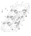
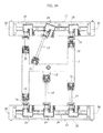
- FIG 1 schematically shows the essential components of an apparatus for injection molding of plastic materials according to a first embodiment of the invention.
- the apparatus comprises an injection machine platen 1, fixed or movable, connected to a plasticization unit partially indicated by 2, for supplying the plastic material to be injected.
- a backing plate or clamping plate 3 is fixed to the injection machine platen 1 of a mold 4, whose matrix is represented schematically.
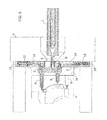
- the plastic material in the fluid state, coming from the plasticization unit 2 is fed through a hole 5 ( Figure 5 ) of the injection machine platen 1 and a hole 6 of the backing plate 3, to a distributor or hot runner 7, connected to the backing plate 3 through a plate of the distributor 7A ("manifold plate").
- the distributor 7 bears one, or as in the case of the example illustrated, a plurality of injectors 8 for injecting the plastic material into the cavity of the mold 4.
- each injector 8 comprises, in a manner known per se, a nozzle 9 within which a pin valve 10 is axially movable, operated in a controlled manner to move between a forward closed position and a retracted open position to enable fluid plastic material to flow from the distributor 7 to the cavity of the mold 4.
- Each unit formed by the relative rotary electric motor 11 and by the screw-and-nut assembly 12 is, for example, of the type described and illustrated in the already cited document EP-2679374A1 : the screw-and-nut assembly 12 is arranged parallel to the side of the rotary electric motor 11, and the screw is driven in rotation, for example by means of a multiplier gearbox, so as to move the nut in one direction or in the opposite direction, thus controlling, correspondingly, the advancing and retracting of the pin valve 10 of the injector 8.
- Each electric motor 11 is controlled by an electronic unit, which operates the control of the position and of the speed of opening/closing of the relative pin valve 10, for example, with sequential modes in the case of molds for the production of large pieces.
- the electric actuators are carried by the distributor 7, as in the case of the already cited document EP-2679374A1 , or by the backing plate of the mold but in the immediate proximity of the relative injectors 8, as in the case of the already cited European patent application no. 14170508.7 .
- the electric actuators or rather, the rotary electric motors 11 with the relative screw-and-nut assemblies 12, actuate the injectors 8 by means of respective connecting rods 14 with variable lengths, i.e. selectable according to the arrangement and the distance of the injectors 8 carried by the distributor 7.
- the rotary electric motors 11 and the screw-and-nut assemblies 12 can be placed in peripheral positions and, in any case, distant from the cavity of the mold 4.
- each rotary electric motor 11, with the respective screw-and-nut assembly 12, forms a unit 25, possibly pre-assembled with the relative connecting rod 14, and directly or indirectly carried by the injection machine platen 1.
- the units 25 are therefore independent and separate, relative to the backing plate 3 and the distributor 7, or rather, relative to the mold 4 as a whole and define, as a complex, a piece of equipment able to be permanently installed on board the molding apparatus to be able to be used with different molds, also in relation to the number and the arrangement of the relative injectors, possibly by simply replacing the connecting rods 14 with others of different lengths.
- the number of units 25 carried by the injection machine platen 1 can also be redundant for use with certain molds, so that they can easily be adapted to a different mold, for example having a great number of injectors, or even the same number or a smaller number of injectors arranged in a different way.
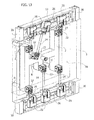
- each unit 25 (rotary electric motor 11/screw-and-nut assembly 12) relative to the injection machine platen 1 can be direct or indirect: in the case of the illustrated example, two hollow supports 13, within which two opposing rows of units 25 are housed, are fixed peripherally to the front side of the injection machine platen 1, on opposite sides with respect to the backing plate 3 of the mold 4.
- Different arrangements are also possible, for example, arranging the units 25 along the entire perimeter of the injection machine platen 1, or rather, in four rows along the four sides of the injection machine platen 1.
- each connecting rod 14 present could be achieved, instead of replacing it with a different-length rod 14, by means of a telescopically extendable and shortenable configuration, which is then lockable at the required length.
- This configuration for example, of the screw-and-nut type, is not illustrated in detail, as it is within the scope of those skilled in the art.
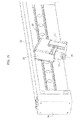
- the connecting rods 14 are moveable within recesses of the backing plate 3, along a direction that may not necessarily parallel to the axis of the screw-and-nut assembly 12, or rather, forming an angle with this axis in the manner, for example, visible in Figure 4 . However, as will be seen, it is preferable that each connecting rod 14 is axially aligned with the relative screw-and-nut assembly 12 and with the respective rocker lever 22.
- each connecting rod 14 is connectable on one side to the screw-and-nut assembly 12 and on the other to the distributor 7 through quick-hooking means, which ensures extreme ease and speed of installing the mold 4 on board the molding apparatus.
- the nut of the assembly 12 is formed with a mushroom-shaped head 15 that passes through a block 16 for securing to the support 13 of the fixed injection machine platen 1, with which a complementary securing element 17 is engaged, connected with a joint, by a pin 18, to one end 19 of the connecting rod 14.
- the other end of the connecting rod 14, indicated by 20, is in turn connected by a pin 21 to a rocker lever 22 carried by a bracket 23 fixed to the distributor 7 and, in turn, connected to the top of the pin valve 10.
- This connection not illustrated in detail, can be, for example, of the type described and illustrated in the already cited document EP-2679374A1 .
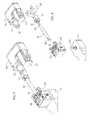
- Figures 9A-9C exemplify the quick-hooking modes between the securing element 17 of the connecting rod 14 and the mushroom-shaped head 15 of the screw-and-nut assembly 12 during the assembly and the subsequent clamping of the mold 4 to the injection machine platen 1. As can be seen, this coupling is achieved following the frontal juxtaposition of the backing plate 3 to the injection machine platen 1.
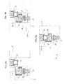
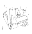
- each rotary electric motor 11 with the respective screw-and-nut assembly 12 is housed in a peripheral recess 28, with the relative connecting rod 14, which extends within a groove 29 of the backing plate 3 for connecting to the corresponding injector 8.
- the connecting rods 14 are coaxial with the screw-and-nut assemblies 12 and with the rocker levers 22.
- the rotary electric motor 11/screw-and-nut 12 assemblies are angularly oriented in a corresponding manner.
- each unit 25 is rotatable on an fitting 27, in turn slidable on the supporting guide 26 and then lockable in the selected position.
- containment boxes 30 are provided at the ends of the supports 13, for the electrical connections of the rotary motors 11 of the units 25.
- these electrical connections are advantageously grouped together, reducing the encumbrances and facilitating the connection to the electronic control unit of the molding apparatus.
- the electric actuators permanently applied to the injection machine platen 1 facilitate the use of different and simplified molds, as these are, in fact, devoid of actuators, and thus simpler and cheaper.
- the electric actuators mounted on the injection machine platen 1 constitute a piece of equipment usable indifferently with diverse molds, which are obviously suitably arranged.
- a further advantage lies in the fact that the electric actuators, no longer exposed to the high temperatures of the distributor, do not require conditioning systems for their cooling. Also, the risk of damage of the electric actuators in the event of leakage of plastic material by the distributor is, in practice, eliminated.
Priority Applications (1)
| Application Number | Priority Date | Filing Date | Title |
|---|---|---|---|
| EP20201257.1A EP3785880B1 (de) | 2014-10-15 | 2015-01-30 | Vorrichtung zum spritzgiessen von kunststoffmaterial |
Applications Claiming Priority (1)
| Application Number | Priority Date | Filing Date | Title |
|---|---|---|---|
| ITTO20140838 | 2014-10-15 |
Related Child Applications (2)
| Application Number | Title | Priority Date | Filing Date |
|---|---|---|---|
| EP20201257.1A Division-Into EP3785880B1 (de) | 2014-10-15 | 2015-01-30 | Vorrichtung zum spritzgiessen von kunststoffmaterial |
| EP20201257.1A Division EP3785880B1 (de) | 2014-10-15 | 2015-01-30 | Vorrichtung zum spritzgiessen von kunststoffmaterial |
Publications (2)
| Publication Number | Publication Date |
|---|---|
| EP3009251A1 true EP3009251A1 (de) | 2016-04-20 |
| EP3009251B1 EP3009251B1 (de) | 2021-06-23 |
Family
ID=51871230
Family Applications (2)
| Application Number | Title | Priority Date | Filing Date |
|---|---|---|---|
| EP20201257.1A Active EP3785880B1 (de) | 2014-10-15 | 2015-01-30 | Vorrichtung zum spritzgiessen von kunststoffmaterial |
| EP15153168.8A Active EP3009251B1 (de) | 2014-10-15 | 2015-01-30 | Vorrichtung zum Spritzgießen von Kunststoffmaterial |
Family Applications Before (1)
| Application Number | Title | Priority Date | Filing Date |
|---|---|---|---|
| EP20201257.1A Active EP3785880B1 (de) | 2014-10-15 | 2015-01-30 | Vorrichtung zum spritzgiessen von kunststoffmaterial |
Country Status (6)
| Country | Link |
|---|---|
| US (1) | US9440386B2 (de) |
| EP (2) | EP3785880B1 (de) |
| JP (1) | JP6570257B2 (de) |
| KR (1) | KR101958516B1 (de) |
| CN (2) | CN105984084B (de) |
| BR (1) | BR102015002589B1 (de) |
Cited By (8)
| Publication number | Priority date | Publication date | Assignee | Title |
|---|---|---|---|---|
| DE202017103242U1 (de) | 2016-05-30 | 2017-06-26 | Inglass S.P.A. | Vorrichtung zum gemeinsamen Spritzgießen mehrerer zu einer Familie gehörender Komponenten aus Kunststoff |
| WO2018129015A1 (en) * | 2017-01-05 | 2018-07-12 | Synventive Molding Solutions, Inc. | Remotely mounted electric motor driving a valve pin in an injection molding apparatus |
| DE102018113404A1 (de) | 2017-06-08 | 2018-12-13 | Inglass S.P.A. | Vorrichtung zum Spritzgießen von Kunststoffmaterialien |
| CN110385836A (zh) * | 2018-04-16 | 2019-10-29 | 英格拉斯股份公司 | 用于塑性材料的注射模塑的装置 |
| EP3380295B1 (de) | 2016-06-09 | 2020-01-22 | Synventive Molding Solutions, Inc. | Kabelübertragung einer aktuatorsteuerung für eine spritzgiessanlage |
| CN111216315A (zh) * | 2019-12-04 | 2020-06-02 | 沈阳金杯延锋汽车内饰系统有限公司 | 用于汽车内饰件的注塑机自动选择供料系统及其控制系统 |
| CN112223649A (zh) * | 2020-09-28 | 2021-01-15 | 长沙隆盛塑业有限公司 | 一种注塑车间的集中供料系统 |
| US11731330B2 (en) | 2020-04-08 | 2023-08-22 | Mold-Masters (2007) Limited | Molten plastic delivery system with push-pull cable actuation |
Families Citing this family (2)
| Publication number | Priority date | Publication date | Assignee | Title |
|---|---|---|---|---|
| IT201800002639A1 (it) * | 2018-02-13 | 2019-08-13 | Inglass Spa | Procedimento e apparecchiatura di stampaggio ad iniezione di materie plastiche |
| CN113119388B (zh) * | 2021-04-25 | 2023-04-18 | 湖南工业职业技术学院 | 一种动漫衍生品快速成型设备 |
Citations (8)
| Publication number | Priority date | Publication date | Assignee | Title |
|---|---|---|---|---|
| US5141696A (en) * | 1986-06-30 | 1992-08-25 | Osuna Diaz J M | Method for injection molding using flow adjusting arrangement |
| JPH08174605A (ja) * | 1994-12-22 | 1996-07-09 | Nissei Plastics Ind Co | 成形装置 |
| US7018198B2 (en) | 2000-10-20 | 2006-03-28 | Delachaux S.A. | Self-sealing injection device for thermoplastic material |
| WO2010126330A2 (ko) | 2009-04-30 | 2010-11-04 | Kim Hyuk Joong | 사출성형기용 핫런너 밸브장치 |
| US8091202B2 (en) | 2009-05-06 | 2012-01-10 | Synventive Molding Solutions, Inc. | Method and apparatus for coupling and uncoupling an injection valve pin |
| DE102011106606A1 (de) * | 2011-06-16 | 2012-12-20 | Psg Plastic Service Gmbh | Vorrichtung zur gleichzeitigen Betätigung einer Vielzahl von Verschlussnadeln in einer Kunststoffspritzmaschine |
| DE102012003574A1 (de) * | 2012-02-27 | 2013-05-02 | Otto Männer Innovation GmbH | Stelleinrichtung zum Verstellen der Nadelventile einer Heißkanal-Spritzgießvorrichtung |
| EP2679374A1 (de) | 2012-06-28 | 2014-01-01 | Inglass S.p.A. | Vorrichtung zum Spritzgießen von Kunststoffmaterialien |
Family Cites Families (16)
| Publication number | Priority date | Publication date | Assignee | Title |
|---|---|---|---|---|
| CA1097872A (en) * | 1978-12-08 | 1981-03-24 | Jobst U. Gellert | Injection molding valve pin actuator mechanism |
| CA1167222A (en) * | 1981-07-15 | 1984-05-15 | Jobst U. Gellert | Valve pin and method of manufacture |
| CA1261579A (en) * | 1987-03-19 | 1989-09-26 | Mold-Masters Limited | Replaceable rocker arm assembly for injection molding system |
| US4919606A (en) * | 1988-12-21 | 1990-04-24 | Gellert Jobst U | Injection molding rack and pinion valve pin actuating mechanism |
| US5067893A (en) * | 1990-06-15 | 1991-11-26 | Osuna Diaz Jesus M | Injection molding apparatus with shut off valve pin actuation system |
| JPH06114887A (ja) | 1992-10-07 | 1994-04-26 | Mitsubishi Materials Corp | 射出成形金型 |
| JP2908971B2 (ja) * | 1993-11-25 | 1999-06-23 | 松下電工株式会社 | 成形金型のホットランナーのゲートの開閉装置 |
| JP3233769B2 (ja) * | 1994-02-14 | 2001-11-26 | 三菱重工業株式会社 | 射出成形機のシャットオフノズル |
| JP2003039501A (ja) * | 2001-08-03 | 2003-02-13 | Canon Inc | ホットランナ装置および射出成形装置 |
| DE102007052597A1 (de) * | 2007-11-03 | 2009-05-07 | Mht Mold & Hotrunner Technology Ag | Angußadapter sowie Angußsystem für einen Angußadapter |
| US20100044896A1 (en) * | 2008-08-21 | 2010-02-25 | Payman Tabassi | Injection Molding Apparatus Having a Nozzle Tip Component for Taking a Nozzle Out of Service |
| CA2822645C (en) * | 2011-02-17 | 2015-10-20 | Husky Injection Molding Systems Ltd. | Mold-tool system including runner assembly configured to provide access portal for permitting access to assembly |
| CN202278710U (zh) * | 2011-03-02 | 2012-06-20 | 深圳市银宝山新科技股份有限公司 | 一种控制注塑模具顺序注射的装置 |
| DE102011016606B4 (de) | 2011-04-09 | 2016-06-02 | Tdc Trade, Development & Construction Ltd. | Verfahren zur Herstellung von Glasschaumprodukten unter Wiederverwertung eines Altglasgemisches |
| CN202053491U (zh) * | 2011-04-25 | 2011-11-30 | 上虞市思纳克热流道有限公司 | 热流道喷嘴阀针调节机构 |
| CN203077534U (zh) * | 2012-12-18 | 2013-07-24 | 柳道万和(苏州)热流道系统有限公司 | 机械式缸体机构 |
-
2015
- 2015-01-30 EP EP20201257.1A patent/EP3785880B1/de active Active
- 2015-01-30 EP EP15153168.8A patent/EP3009251B1/de active Active
- 2015-02-06 JP JP2015022486A patent/JP6570257B2/ja active Active
- 2015-02-06 BR BR102015002589-0A patent/BR102015002589B1/pt active IP Right Grant
- 2015-02-09 US US14/616,828 patent/US9440386B2/en active Active
- 2015-02-10 CN CN201510068499.4A patent/CN105984084B/zh active Active
- 2015-02-10 CN CN201811530919.6A patent/CN110065205B/zh active Active
- 2015-02-10 KR KR1020150020014A patent/KR101958516B1/ko active IP Right Grant
Patent Citations (9)
| Publication number | Priority date | Publication date | Assignee | Title |
|---|---|---|---|---|
| US5141696A (en) * | 1986-06-30 | 1992-08-25 | Osuna Diaz J M | Method for injection molding using flow adjusting arrangement |
| JPH08174605A (ja) * | 1994-12-22 | 1996-07-09 | Nissei Plastics Ind Co | 成形装置 |
| US7018198B2 (en) | 2000-10-20 | 2006-03-28 | Delachaux S.A. | Self-sealing injection device for thermoplastic material |
| WO2010126330A2 (ko) | 2009-04-30 | 2010-11-04 | Kim Hyuk Joong | 사출성형기용 핫런너 밸브장치 |
| US8091202B2 (en) | 2009-05-06 | 2012-01-10 | Synventive Molding Solutions, Inc. | Method and apparatus for coupling and uncoupling an injection valve pin |
| US8282388B2 (en) | 2009-05-06 | 2012-10-09 | Synventive Molding Solutions, Inc. | Apparatus for coupling and uncoupling an injection valve pin |
| DE102011106606A1 (de) * | 2011-06-16 | 2012-12-20 | Psg Plastic Service Gmbh | Vorrichtung zur gleichzeitigen Betätigung einer Vielzahl von Verschlussnadeln in einer Kunststoffspritzmaschine |
| DE102012003574A1 (de) * | 2012-02-27 | 2013-05-02 | Otto Männer Innovation GmbH | Stelleinrichtung zum Verstellen der Nadelventile einer Heißkanal-Spritzgießvorrichtung |
| EP2679374A1 (de) | 2012-06-28 | 2014-01-01 | Inglass S.p.A. | Vorrichtung zum Spritzgießen von Kunststoffmaterialien |
Cited By (12)
| Publication number | Priority date | Publication date | Assignee | Title |
|---|---|---|---|---|
| DE202017103242U1 (de) | 2016-05-30 | 2017-06-26 | Inglass S.P.A. | Vorrichtung zum gemeinsamen Spritzgießen mehrerer zu einer Familie gehörender Komponenten aus Kunststoff |
| ITUA20163913A1 (it) * | 2016-05-30 | 2017-11-30 | Inglass Spa | Apparecchiatura e procedimento di stampaggio ad iniezione congiunto di componenti di materia plastica appartenenti ad una stessa famiglia |
| EP3380295B1 (de) | 2016-06-09 | 2020-01-22 | Synventive Molding Solutions, Inc. | Kabelübertragung einer aktuatorsteuerung für eine spritzgiessanlage |
| EP3380295B2 (de) † | 2016-06-09 | 2022-11-09 | Synventive Molding Solutions, Inc. | Kabelübertragung einer aktuatorsteuerung für eine spritzgiessanlage |
| WO2018129015A1 (en) * | 2017-01-05 | 2018-07-12 | Synventive Molding Solutions, Inc. | Remotely mounted electric motor driving a valve pin in an injection molding apparatus |
| US10792849B2 (en) | 2017-01-05 | 2020-10-06 | Synventive Molding Solutions, Inc. | Remotely mounted electric motor driving a valve pin in an injection molding apparatus |
| DE102018113404A1 (de) | 2017-06-08 | 2018-12-13 | Inglass S.P.A. | Vorrichtung zum Spritzgießen von Kunststoffmaterialien |
| DE102018113404B4 (de) | 2017-06-08 | 2023-03-09 | Inglass S.P.A. | Vorrichtung zum Spritzgießen von Kunststoffmaterialien |
| CN110385836A (zh) * | 2018-04-16 | 2019-10-29 | 英格拉斯股份公司 | 用于塑性材料的注射模塑的装置 |
| CN111216315A (zh) * | 2019-12-04 | 2020-06-02 | 沈阳金杯延锋汽车内饰系统有限公司 | 用于汽车内饰件的注塑机自动选择供料系统及其控制系统 |
| US11731330B2 (en) | 2020-04-08 | 2023-08-22 | Mold-Masters (2007) Limited | Molten plastic delivery system with push-pull cable actuation |
| CN112223649A (zh) * | 2020-09-28 | 2021-01-15 | 长沙隆盛塑业有限公司 | 一种注塑车间的集中供料系统 |
Also Published As
| Publication number | Publication date |
|---|---|
| JP2016078430A (ja) | 2016-05-16 |
| US9440386B2 (en) | 2016-09-13 |
| CN110065205A (zh) | 2019-07-30 |
| US20160107352A1 (en) | 2016-04-21 |
| JP6570257B2 (ja) | 2019-09-04 |
| CN105984084A (zh) | 2016-10-05 |
| EP3009251B1 (de) | 2021-06-23 |
| BR102015002589A2 (pt) | 2017-02-14 |
| EP3785880B1 (de) | 2022-05-04 |
| KR101958516B1 (ko) | 2019-03-14 |
| CN105984084B (zh) | 2019-04-09 |
| CN110065205B (zh) | 2021-10-29 |
| EP3785880A1 (de) | 2021-03-03 |
| KR20160044398A (ko) | 2016-04-25 |
| BR102015002589B1 (pt) | 2020-12-08 |
Similar Documents
| Publication | Publication Date | Title |
|---|---|---|
| US9440386B2 (en) | Apparatus for injection molding of plastic material | |
| US9452557B2 (en) | Hot runner system | |
| EP2918389B1 (de) | Befestigungsplatte der Form einer Spritzgussvorrichtung für Kunststoffmaterial | |
| US20180264698A1 (en) | Apparatus for injection moulding of plastic materials | |
| KR101342889B1 (ko) | 복합 성형품용 사출성형기 및 그 성형방법 | |
| CN110366482B (zh) | 注射成型机 | |
| US9180613B2 (en) | Side actuated shooting pot | |
| CA2682122C (en) | Molding system having clamp actuator having actuator mount | |
| EP3117977B1 (de) | Werkzeughälfte für ein formwerkzeug einer spritzgiessmaschine mit einem heisskanalsystem | |
| EP3628465B1 (de) | Kunststoff-spritzgussmaschine und formverfahren | |
| US9138926B2 (en) | Apparatus and method for injection molding | |
| CA2607390A1 (en) | A robor for an injection molding system | |
| CN110315705B (zh) | 顶出装置 | |
| US6811392B2 (en) | Traction type electric injection molding machine | |
| CN110315715B (zh) | 注射成型机 |
Legal Events
| Date | Code | Title | Description |
|---|---|---|---|
| PUAI | Public reference made under article 153(3) epc to a published international application that has entered the european phase |
Free format text: ORIGINAL CODE: 0009012 |
|
| AK | Designated contracting states |
Kind code of ref document: A1 Designated state(s): AL AT BE BG CH CY CZ DE DK EE ES FI FR GB GR HR HU IE IS IT LI LT LU LV MC MK MT NL NO PL PT RO RS SE SI SK SM TR |
|
| AX | Request for extension of the european patent |
Extension state: BA ME |
|
| 17P | Request for examination filed |
Effective date: 20161019 |
|
| RBV | Designated contracting states (corrected) |
Designated state(s): AL AT BE BG CH CY CZ DE DK EE ES FI FR GB GR HR HU IE IS IT LI LT LU LV MC MK MT NL NO PL PT RO RS SE SI SK SM TR |
|
| STAA | Information on the status of an ep patent application or granted ep patent |
Free format text: STATUS: EXAMINATION IS IN PROGRESS |
|
| 17Q | First examination report despatched |
Effective date: 20180725 |
|
| STAA | Information on the status of an ep patent application or granted ep patent |
Free format text: STATUS: EXAMINATION IS IN PROGRESS |
|
| GRAP | Despatch of communication of intention to grant a patent |
Free format text: ORIGINAL CODE: EPIDOSNIGR1 |
|
| STAA | Information on the status of an ep patent application or granted ep patent |
Free format text: STATUS: GRANT OF PATENT IS INTENDED |
|
| RIC1 | Information provided on ipc code assigned before grant |
Ipc: B29C 45/17 20060101ALN20210118BHEP Ipc: B29C 45/28 20060101AFI20210118BHEP |
|
| INTG | Intention to grant announced |
Effective date: 20210209 |
|
| GRAS | Grant fee paid |
Free format text: ORIGINAL CODE: EPIDOSNIGR3 |
|
| GRAA | (expected) grant |
Free format text: ORIGINAL CODE: 0009210 |
|
| STAA | Information on the status of an ep patent application or granted ep patent |
Free format text: STATUS: THE PATENT HAS BEEN GRANTED |
|
| AK | Designated contracting states |
Kind code of ref document: B1 Designated state(s): AL AT BE BG CH CY CZ DE DK EE ES FI FR GB GR HR HU IE IS IT LI LT LU LV MC MK MT NL NO PL PT RO RS SE SI SK SM TR |
|
| REG | Reference to a national code |
Ref country code: GB Ref legal event code: FG4D |
|
| REG | Reference to a national code |
Ref country code: CH Ref legal event code: EP |
|
| REG | Reference to a national code |
Ref country code: DE Ref legal event code: R096 Ref document number: 602015070583 Country of ref document: DE Ref country code: AT Ref legal event code: REF Ref document number: 1403915 Country of ref document: AT Kind code of ref document: T Effective date: 20210715 |
|
| REG | Reference to a national code |
Ref country code: IE Ref legal event code: FG4D |
|
| REG | Reference to a national code |
Ref country code: LT Ref legal event code: MG9D |
|
| PG25 | Lapsed in a contracting state [announced via postgrant information from national office to epo] |
Ref country code: HR Free format text: LAPSE BECAUSE OF FAILURE TO SUBMIT A TRANSLATION OF THE DESCRIPTION OR TO PAY THE FEE WITHIN THE PRESCRIBED TIME-LIMIT Effective date: 20210623 Ref country code: BG Free format text: LAPSE BECAUSE OF FAILURE TO SUBMIT A TRANSLATION OF THE DESCRIPTION OR TO PAY THE FEE WITHIN THE PRESCRIBED TIME-LIMIT Effective date: 20210923 Ref country code: LT Free format text: LAPSE BECAUSE OF FAILURE TO SUBMIT A TRANSLATION OF THE DESCRIPTION OR TO PAY THE FEE WITHIN THE PRESCRIBED TIME-LIMIT Effective date: 20210623 Ref country code: FI Free format text: LAPSE BECAUSE OF FAILURE TO SUBMIT A TRANSLATION OF THE DESCRIPTION OR TO PAY THE FEE WITHIN THE PRESCRIBED TIME-LIMIT Effective date: 20210623 |
|
| REG | Reference to a national code |
Ref country code: AT Ref legal event code: MK05 Ref document number: 1403915 Country of ref document: AT Kind code of ref document: T Effective date: 20210623 |
|
| PG25 | Lapsed in a contracting state [announced via postgrant information from national office to epo] |
Ref country code: RS Free format text: LAPSE BECAUSE OF FAILURE TO SUBMIT A TRANSLATION OF THE DESCRIPTION OR TO PAY THE FEE WITHIN THE PRESCRIBED TIME-LIMIT Effective date: 20210623 Ref country code: SE Free format text: LAPSE BECAUSE OF FAILURE TO SUBMIT A TRANSLATION OF THE DESCRIPTION OR TO PAY THE FEE WITHIN THE PRESCRIBED TIME-LIMIT Effective date: 20210623 Ref country code: NO Free format text: LAPSE BECAUSE OF FAILURE TO SUBMIT A TRANSLATION OF THE DESCRIPTION OR TO PAY THE FEE WITHIN THE PRESCRIBED TIME-LIMIT Effective date: 20210923 Ref country code: LV Free format text: LAPSE BECAUSE OF FAILURE TO SUBMIT A TRANSLATION OF THE DESCRIPTION OR TO PAY THE FEE WITHIN THE PRESCRIBED TIME-LIMIT Effective date: 20210623 Ref country code: GR Free format text: LAPSE BECAUSE OF FAILURE TO SUBMIT A TRANSLATION OF THE DESCRIPTION OR TO PAY THE FEE WITHIN THE PRESCRIBED TIME-LIMIT Effective date: 20210924 |
|
| REG | Reference to a national code |
Ref country code: NL Ref legal event code: MP Effective date: 20210623 |
|
| PG25 | Lapsed in a contracting state [announced via postgrant information from national office to epo] |
Ref country code: SK Free format text: LAPSE BECAUSE OF FAILURE TO SUBMIT A TRANSLATION OF THE DESCRIPTION OR TO PAY THE FEE WITHIN THE PRESCRIBED TIME-LIMIT Effective date: 20210623 Ref country code: SM Free format text: LAPSE BECAUSE OF FAILURE TO SUBMIT A TRANSLATION OF THE DESCRIPTION OR TO PAY THE FEE WITHIN THE PRESCRIBED TIME-LIMIT Effective date: 20210623 Ref country code: EE Free format text: LAPSE BECAUSE OF FAILURE TO SUBMIT A TRANSLATION OF THE DESCRIPTION OR TO PAY THE FEE WITHIN THE PRESCRIBED TIME-LIMIT Effective date: 20210623 Ref country code: CZ Free format text: LAPSE BECAUSE OF FAILURE TO SUBMIT A TRANSLATION OF THE DESCRIPTION OR TO PAY THE FEE WITHIN THE PRESCRIBED TIME-LIMIT Effective date: 20210623 Ref country code: AT Free format text: LAPSE BECAUSE OF FAILURE TO SUBMIT A TRANSLATION OF THE DESCRIPTION OR TO PAY THE FEE WITHIN THE PRESCRIBED TIME-LIMIT Effective date: 20210623 Ref country code: ES Free format text: LAPSE BECAUSE OF FAILURE TO SUBMIT A TRANSLATION OF THE DESCRIPTION OR TO PAY THE FEE WITHIN THE PRESCRIBED TIME-LIMIT Effective date: 20210623 Ref country code: RO Free format text: LAPSE BECAUSE OF FAILURE TO SUBMIT A TRANSLATION OF THE DESCRIPTION OR TO PAY THE FEE WITHIN THE PRESCRIBED TIME-LIMIT Effective date: 20210623 Ref country code: NL Free format text: LAPSE BECAUSE OF FAILURE TO SUBMIT A TRANSLATION OF THE DESCRIPTION OR TO PAY THE FEE WITHIN THE PRESCRIBED TIME-LIMIT Effective date: 20210623 Ref country code: PT Free format text: LAPSE BECAUSE OF FAILURE TO SUBMIT A TRANSLATION OF THE DESCRIPTION OR TO PAY THE FEE WITHIN THE PRESCRIBED TIME-LIMIT Effective date: 20211025 |
|
| PG25 | Lapsed in a contracting state [announced via postgrant information from national office to epo] |
Ref country code: PL Free format text: LAPSE BECAUSE OF FAILURE TO SUBMIT A TRANSLATION OF THE DESCRIPTION OR TO PAY THE FEE WITHIN THE PRESCRIBED TIME-LIMIT Effective date: 20210623 |
|
| REG | Reference to a national code |
Ref country code: DE Ref legal event code: R097 Ref document number: 602015070583 Country of ref document: DE |
|
| PG25 | Lapsed in a contracting state [announced via postgrant information from national office to epo] |
Ref country code: DK Free format text: LAPSE BECAUSE OF FAILURE TO SUBMIT A TRANSLATION OF THE DESCRIPTION OR TO PAY THE FEE WITHIN THE PRESCRIBED TIME-LIMIT Effective date: 20210623 |
|
| PLBE | No opposition filed within time limit |
Free format text: ORIGINAL CODE: 0009261 |
|
| STAA | Information on the status of an ep patent application or granted ep patent |
Free format text: STATUS: NO OPPOSITION FILED WITHIN TIME LIMIT |
|
| 26N | No opposition filed |
Effective date: 20220324 |
|
| PG25 | Lapsed in a contracting state [announced via postgrant information from national office to epo] |
Ref country code: AL Free format text: LAPSE BECAUSE OF FAILURE TO SUBMIT A TRANSLATION OF THE DESCRIPTION OR TO PAY THE FEE WITHIN THE PRESCRIBED TIME-LIMIT Effective date: 20210623 |
|
| PG25 | Lapsed in a contracting state [announced via postgrant information from national office to epo] |
Ref country code: MC Free format text: LAPSE BECAUSE OF FAILURE TO SUBMIT A TRANSLATION OF THE DESCRIPTION OR TO PAY THE FEE WITHIN THE PRESCRIBED TIME-LIMIT Effective date: 20210623 |
|
| REG | Reference to a national code |
Ref country code: CH Ref legal event code: PL |
|
| GBPC | Gb: european patent ceased through non-payment of renewal fee |
Effective date: 20220130 |
|
| REG | Reference to a national code |
Ref country code: BE Ref legal event code: MM Effective date: 20220131 |
|
| PG25 | Lapsed in a contracting state [announced via postgrant information from national office to epo] |
Ref country code: LU Free format text: LAPSE BECAUSE OF NON-PAYMENT OF DUE FEES Effective date: 20220130 Ref country code: GB Free format text: LAPSE BECAUSE OF NON-PAYMENT OF DUE FEES Effective date: 20220130 |
|
| PG25 | Lapsed in a contracting state [announced via postgrant information from national office to epo] |
Ref country code: FR Free format text: LAPSE BECAUSE OF NON-PAYMENT OF DUE FEES Effective date: 20220131 Ref country code: BE Free format text: LAPSE BECAUSE OF NON-PAYMENT OF DUE FEES Effective date: 20220131 |
|
| PG25 | Lapsed in a contracting state [announced via postgrant information from national office to epo] |
Ref country code: LI Free format text: LAPSE BECAUSE OF NON-PAYMENT OF DUE FEES Effective date: 20220131 Ref country code: CH Free format text: LAPSE BECAUSE OF NON-PAYMENT OF DUE FEES Effective date: 20220131 |
|
| PG25 | Lapsed in a contracting state [announced via postgrant information from national office to epo] |
Ref country code: IE Free format text: LAPSE BECAUSE OF NON-PAYMENT OF DUE FEES Effective date: 20220130 |
|
| PGFP | Annual fee paid to national office [announced via postgrant information from national office to epo] |
Ref country code: IT Payment date: 20230103 Year of fee payment: 9 Ref country code: DE Payment date: 20221220 Year of fee payment: 9 |
|
| P01 | Opt-out of the competence of the unified patent court (upc) registered |
Effective date: 20230515 |
|
| PG25 | Lapsed in a contracting state [announced via postgrant information from national office to epo] |
Ref country code: HU Free format text: LAPSE BECAUSE OF FAILURE TO SUBMIT A TRANSLATION OF THE DESCRIPTION OR TO PAY THE FEE WITHIN THE PRESCRIBED TIME-LIMIT; INVALID AB INITIO Effective date: 20150130 |