EP3007916B1 - Verfahren und vorrichtung zum lokalisieren von rädern eines fahrzeugs sowie reifendruckkontrollsystem - Google Patents
Verfahren und vorrichtung zum lokalisieren von rädern eines fahrzeugs sowie reifendruckkontrollsystem Download PDFInfo
- Publication number
- EP3007916B1 EP3007916B1 EP14729023.3A EP14729023A EP3007916B1 EP 3007916 B1 EP3007916 B1 EP 3007916B1 EP 14729023 A EP14729023 A EP 14729023A EP 3007916 B1 EP3007916 B1 EP 3007916B1
- Authority
- EP
- European Patent Office
- Prior art keywords
- wheel
- rotary angle
- time
- packets
- time interval
- Prior art date
- Legal status (The legal status is an assumption and is not a legal conclusion. Google has not performed a legal analysis and makes no representation as to the accuracy of the status listed.)
- Active
Links
Images


Classifications
-
- B—PERFORMING OPERATIONS; TRANSPORTING
- B60—VEHICLES IN GENERAL
- B60C—VEHICLE TYRES; TYRE INFLATION; TYRE CHANGING; CONNECTING VALVES TO INFLATABLE ELASTIC BODIES IN GENERAL; DEVICES OR ARRANGEMENTS RELATED TO TYRES
- B60C23/00—Devices for measuring, signalling, controlling, or distributing tyre pressure or temperature, specially adapted for mounting on vehicles; Arrangement of tyre inflating devices on vehicles, e.g. of pumps or of tanks; Tyre cooling arrangements
- B60C23/02—Signalling devices actuated by tyre pressure
- B60C23/04—Signalling devices actuated by tyre pressure mounted on the wheel or tyre
- B60C23/0408—Signalling devices actuated by tyre pressure mounted on the wheel or tyre transmitting the signals by non-mechanical means from the wheel or tyre to a vehicle body mounted receiver
- B60C23/0415—Automatically identifying wheel mounted units, e.g. after replacement or exchange of wheels
- B60C23/0416—Automatically identifying wheel mounted units, e.g. after replacement or exchange of wheels allocating a corresponding wheel position on vehicle, e.g. front/left or rear/right
-
- B—PERFORMING OPERATIONS; TRANSPORTING
- B60—VEHICLES IN GENERAL
- B60C—VEHICLE TYRES; TYRE INFLATION; TYRE CHANGING; CONNECTING VALVES TO INFLATABLE ELASTIC BODIES IN GENERAL; DEVICES OR ARRANGEMENTS RELATED TO TYRES
- B60C19/00—Tyre parts or constructions not otherwise provided for
-
- B—PERFORMING OPERATIONS; TRANSPORTING
- B60—VEHICLES IN GENERAL
- B60C—VEHICLE TYRES; TYRE INFLATION; TYRE CHANGING; CONNECTING VALVES TO INFLATABLE ELASTIC BODIES IN GENERAL; DEVICES OR ARRANGEMENTS RELATED TO TYRES
- B60C23/00—Devices for measuring, signalling, controlling, or distributing tyre pressure or temperature, specially adapted for mounting on vehicles; Arrangement of tyre inflating devices on vehicles, e.g. of pumps or of tanks; Tyre cooling arrangements
- B60C23/02—Signalling devices actuated by tyre pressure
- B60C23/04—Signalling devices actuated by tyre pressure mounted on the wheel or tyre
- B60C23/0486—Signalling devices actuated by tyre pressure mounted on the wheel or tyre comprising additional sensors in the wheel or tyre mounted monitoring device, e.g. movement sensors, microphones or earth magnetic field sensors
- B60C23/0489—Signalling devices actuated by tyre pressure mounted on the wheel or tyre comprising additional sensors in the wheel or tyre mounted monitoring device, e.g. movement sensors, microphones or earth magnetic field sensors for detecting the actual angular position of the monitoring device while the wheel is turning
-
- B—PERFORMING OPERATIONS; TRANSPORTING
- B60—VEHICLES IN GENERAL
- B60C—VEHICLE TYRES; TYRE INFLATION; TYRE CHANGING; CONNECTING VALVES TO INFLATABLE ELASTIC BODIES IN GENERAL; DEVICES OR ARRANGEMENTS RELATED TO TYRES
- B60C19/00—Tyre parts or constructions not otherwise provided for
- B60C2019/004—Tyre sensors other than for detecting tyre pressure
Definitions
- the present invention relates to a method and a device for locating wheels of a vehicle, in which or at least one wheel has wheel electronics. Moreover, the present invention relates to a tire pressure monitoring system with such a device.
- tire pressure monitoring systems which are characterized in that at least one wheel is equipped with a direct measuring wheel electronics. If all wheels are equipped with wheel electronics that send corresponding data to a vehicle-side receiver, there is a desire to be able to indicate to the driver from which wheel, that is, from which wheel position, data was sent. In this way, it is possible to tell the driver at a detected pressure drop directly which of the wheels located on the vehicle loses pressure.
- the invention comprises a method for locating wheels of a vehicle, in which at least one wheel has wheel electronics, wherein the following steps are carried out on the vehicle side.
- a signal is received from the wheel electronics, which allows conclusions about a time at which the wheel has taken a first rotational angular position.
- a first rotation angle information is generated.
- Second angular positions of the wheels are determined by sensors, which are each assigned to a specific position on the vehicle.
- second rotational angle information is provided.
- the first rotation angle information is compared with the second rotation angle information.
- the wheel associated with the wheel electronics is located depending on this comparison.
- the signal consists of several packets that are received with a time delay.
- the step of generating the first rotational angle information in this case has the step of determining the point in time at which the wheel has assumed the first rotational angular position based on one of the plurality of packets. On the vehicle side, at least one time interval between the packets is determined and based on the determined At least one time interval is provided at least one estimated value for the at least one time interval.
- each packet has a number indicating which rank the packet occupies within an order of the plurality of packets. If a received signal does not include a first packet, the step of determining the time at which the wheel has assumed the first rotational angle position is based on the at least one estimate of the at least one time interval and the number of a packet.
- the step of determining at least one time interval between the packets can be carried out several times and the determined time intervals can be stored accordingly.
- the method is executed in several consecutive periods and only the temporal ones Distances of the most recent n periods are stored, where n may be, in particular, a natural number.
- n may be, in particular, a natural number.
- This can be implemented, for example, by means of a ring buffer. In this way the storage space requirement is reduced.
- the step of providing at least one estimated value may comprise the step of forming at least one average value from the stored time intervals.
- the stored time intervals are thus averaged in this case to generate a more robust estimate in this way.
- the step of providing at least one estimated value comprises the following steps.
- a first product is calculated by multiplying the at least one time interval determined in a current period by a predetermined value that is between 0 and 1.
- a second product can be calculated by multiplying an estimate of a previous period by 1 minus the predetermined value.
- this preceding period may be the period immediately preceding the current period.
- the estimated value of the current period can then be calculated.
- the memory requirement is minimized because the at least one estimate is stored for only one period.
- the step of determining at least a time interval between the packets is performed in one embodiment only if the received signal includes all the expected packets. In this way, it should be prevented that incorrect time intervals are determined by a possible lack of a package.
- the present invention includes a device for locating wheels of a vehicle, in which at least a wheel has a wheel electronics.
- the device has a first receiving unit for receiving a signal from the wheel electronics, the signal allowing conclusions to be drawn on a time at which the wheel has assumed a first rotational angular position.
- a first processing unit is for generating a first rotation angle information based on the signal.
- a second receiving unit of the device is used for receiving second rotational angular positions of the wheels measured by sensors, which are each assigned to a specific position on the vehicle.
- the apparatus includes a second processing unit for providing second rotational angle information based on the second rotational angular positions.
- An adjustment unit is set up to adjust the first rotation angle information with second rotation angle information.
- a localization unit serves to locate the wheel associated with the wheel electronics as a function of a result of the adjustment unit.
- the first receiving unit is configured to receive a signal that consists of several packets that are received with a time delay.
- the first processing unit is configured to determine a point of time when the wheel has assumed the first rotational angle position based on one of the plurality of packets.
- the device has a distance determining device for determining at least one time interval between the packets.
- the device comprises an estimating device for providing at least one estimated value for the at least one time interval based on the determined at least one time interval.
- the present invention comprises a tire pressure monitoring system with a device according to the invention.
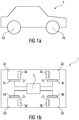
- FIG. 1a shows a vehicle 1 in a side view.
- the two wheels 2b and 2d can be seen.
- the same vehicle is in FIG. 1b shown again from below, with essential elements of a tire pressure monitoring system are shown.
- the four wheels 2a to 2d each have wheel electronics 3a to 3d.
- the wheels 2a to 2d are each assigned sensors 4a to 4d arranged on the vehicle side. These sensors may be, for example, ABS sensors or ESP sensors.
- the sensors 4a to 4d are connected to an embodiment of a device 5 according to the invention. This is among other things set up to receive signals from the wheel electronics 3a to 3d.
- FIG. 2 shows the wheel 2a again in a side view, it can be seen that the wheel electronics rotates 3a when rolling the wheel 2a on the ground 6 with the wheel.
- the wheel unit 3a transmits a signal 7, which in the FIG. 3 is shown and includes the packets 7a, 7b and 7c.
- the wheel unit 3a transmits a plurality of packages because the receiving unit arranged on the vehicle side may not be able to receive one or more of the packages, for example due to shading by body panels.
- the time t is plotted.
- the wheel passes through the first rotational angle position. This may be, for example, the highest position in the wheel (0 °) or around the center of the tire contact patch (180 °) or the entry or exit point in or out of the tire contact patch.
- the first packet 7a is sent.
- the delay time dt 0 may be predetermined or determined during operation by the wheel electronics.
- the packet 7a has been completely received on the vehicle side.
- the distance between the first packet 7a and the second packet 7b is dt 1
- the distance between the second packet 7b and the third packet 7c is dt 2 .
- the second package 7b is completely received at time t 2 and the packet 7c at the time T3.
- the distances between the packets dt 1 and dt 2 are continuously measured and on their basis, estimates of these distances are provided.
- the delay time dt 0 is well known with reference to the clock of the wheel electronics.
- the ratio of the distance estimated by the vehicle dt 1 compared to one of the wheel well known distance between the first and second package with respect to the clock of the wheel electronics dt 0 can be adapted to any clock deviations. Knowing the delay time dt 0 and the distances dt 1 and dt 2 and the transmission durations for the packets 7a, 7b and 7c could be calculated back, for example, from the time of reception t 3 of the third packet to the time t 0 , at which the wheel assumed the first rotational angular position Has. To deduce from t 2 to t 0 , only the distances dt 0 and dt 1 and the transmission durations of the packets 7a and 7b need to be known.
- the invention is not limited to a signal with three packets. Rather, any number of packets may be used as long as the number is at least two.
- the angular inaccuracy of 75 ° has the consequence that the localization usually takes longer and may even not converge at all.
- the distances dt 1 and dt 2 are firmly programmed in the vehicle-mounted control unit. They are therefore not calculated regularly to provide up to date estimates for to provide the time intervals so that it at the US 8,332,104 B2 to the angle inaccuracies just described, which cause the process to converge only slowly.
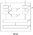
- FIG. 4a shows an embodiment of a device for locating wheels of a vehicle, in which at least one wheel has wheel electronics.
- the illustrated device 8 comprises a first receiving unit 9 for receiving a signal from the wheel electronics, which allows conclusions to a time t 0 , at which the wheel has assumed a first rotational angular position.
- the receiving unit is configured to receive a signal consisting of a plurality of packets received in a time-shifted manner.
- the device 8 has a first processing unit 10 for generating a first rotation angle information based on the signal. This is set up to determine, based on one of the multiple packets, a time t 0 at which the wheel has assumed the first rotational angular position.
- the first processing unit 10 is connected to a distance determining device 11 for determining at least one time interval between the packets and an estimating device 12 for providing at least one estimated value for the at least one time interval based on the determined at least one time interval.
- the device 8 comprises a second receiving unit 13 for receiving rotational angular positions of the wheels measured by sensors which are each assigned to a specific position on the vehicle. These may be, for example, ABS or ESP sensors.
- a second processing unit 14 provides second rotational angle information based on the second rotational angular positions. These may in particular be the times at which, from the perspective of the sensors, the assigned wheel has assumed the second rotational angular position, which preferably corresponds to the first rotational angular position.
- An adjustment unit 15 uses the first rotation angle information of the first processing unit 10 and the second rotation angle information of the second processing unit 14 and compares them with each other. Depending on the result of the balancing unit 15, the locating unit 16 locates the wheel associated with the wheel electronics.
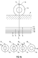
- FIG. 4b shows above the wheel 2c with a wheel electronics 3c, which is currently in the first rotational angular position ⁇ .
- the first rotation angle information indicates when the wheel electronics 3c was in the first rotation angle position ⁇ . In the present example, therefore, the first rotation angle information corresponds to t 0 .
- time bars are plotted.
- the bar B1 indicates that the wheel 2a was at the second rotational angular position at time t a .
- the beam B2 illustrates that the wheel 2b was located at the second rotational angular position at time t b .
- the bars B3 and B4 correspond to the wheels 2c and 2d.
- the wheel 2c has assumed the second rotational angular position at time t c , while the wheel 2 d was at this second rotational angular position at time t d .
- the wheels 2a - 2d with their wheel electronics 3a - 3d are shown at time t 0 .
- the wheel electronics 3a is located at time t 0 even before the second rotational angular position ⁇ . 1 Consequently, it passes through the rotational angle position after t 0 , as the beam B1 illustrates.
- the wheel electronics 3b has already passed through the second rotational angular position ⁇ 2 .
- the wheel electronics 3 c is located at the time t 0 almost exactly in the second rotational angular position ⁇ 3 from the perspective of the sensor, which is permanently assigned to the corresponding position on the vehicle.
- the wheel electronics t d has already passed through the second rotational angle position ⁇ 4 for the longest time at time t 0 .
- the time t c is closest to the time t 0 , so that it can be concluded by a corresponding adjustment that the wheel electronics, which has sent the received signal, the wheel electronics 3c, which is associated with the wheel 2c.
- the deviations between t0 and tc can result in particular from measurement inaccuracies.
- the wheel can be located accordingly.
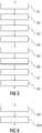
- FIG. 5 shows steps of an embodiment of a method according to the invention.
- step S1 first a first rotational angular position of a wheel is determined to which the wheel electronics are assigned.
- step S2 a signal is then sent from the wheel electronics to a vehicle-side receiver, which allows conclusions to a point in time at which the wheel has assumed the first rotational angular position. This signal is received in step S3.
- a first rotation angle information is generated in step S4. This includes determining the point in time at which the wheel has assumed the first rotational angular position. This is based on one of several packages.
- step S5 second rotational angular positions of the wheels are determined by sensors each associated with a specific position on the vehicle. Based on these second rotational angular positions, second rotational angle information is provided (step S6). Subsequently, in step S7, the first rotational angle information is compared with the second rotational angle information so as to localize the wheel associated with the wheel electronics in step S8 as a function of this comparison.
- FIG. 6 illustrates an embodiment of a routine that provides an estimate for the method of the invention.
- a time interval between the receiving packets is determined.
- At least one estimated value for the at least one time interval is then provided based on the determined at least one time interval.
- said time can be based on the at least one estimated value for the at least one time interval and the number of a packet.
- FIG. 7 shows a further embodiment of a routine that provides an estimate for the inventive method.
- an actual time interval A t is determined in step S11 in the current period t.
- a t as already stated above, the current time interval in the current period and S t denotes the estimated value in the current period.
- S t-1 is the estimate of the previous period. ⁇ symbolizes a value between 0 and 1.
- the current time interval in the current period A t is therefore weighted as a correction factor to the estimated value of the preceding period S t-1 in the estimated value of the current period S t . In this way, only one estimate must be stored in each period, which is updated accordingly.
- each of the packets can be used to draw conclusions about the time at which the wheel has assumed the first rotational angular position.
- the time intervals can be determined repeatedly, so that deviations of the clocks of the wheel units with each other and their inaccuracies are compensated.
Landscapes
- Engineering & Computer Science (AREA)
- Mechanical Engineering (AREA)
- Measuring Fluid Pressure (AREA)
- Arrangements For Transmission Of Measured Signals (AREA)
Applications Claiming Priority (2)
| Application Number | Priority Date | Filing Date | Title |
|---|---|---|---|
| DE102013211152.5A DE102013211152A1 (de) | 2013-06-14 | 2013-06-14 | Verfahren und Vorrichtung zum Lokalisieren von Rädern eines Fahrzeugs sowie Reifendruckkontrollsystem |
| PCT/EP2014/062151 WO2014198785A1 (de) | 2013-06-14 | 2014-06-11 | Verfahren und vorrichtung zum lokalisieren von rädern eines fahrzeugs sowie reifendruckkontrollsystem |
Publications (2)
| Publication Number | Publication Date |
|---|---|
| EP3007916A1 EP3007916A1 (de) | 2016-04-20 |
| EP3007916B1 true EP3007916B1 (de) | 2017-03-29 |
Family
ID=50897655
Family Applications (1)
| Application Number | Title | Priority Date | Filing Date |
|---|---|---|---|
| EP14729023.3A Active EP3007916B1 (de) | 2013-06-14 | 2014-06-11 | Verfahren und vorrichtung zum lokalisieren von rädern eines fahrzeugs sowie reifendruckkontrollsystem |
Country Status (7)
| Country | Link |
|---|---|
| US (1) | US10173479B2 (enExample) |
| EP (1) | EP3007916B1 (enExample) |
| JP (1) | JP6391679B2 (enExample) |
| KR (1) | KR101867740B1 (enExample) |
| CN (1) | CN105307877B (enExample) |
| DE (1) | DE102013211152A1 (enExample) |
| WO (1) | WO2014198785A1 (enExample) |
Families Citing this family (8)
| Publication number | Priority date | Publication date | Assignee | Title |
|---|---|---|---|---|
| EP2993064B1 (en) * | 2014-09-03 | 2018-02-28 | Continental Automotive GmbH | Method and system for determining a rotation angle of at least one wheel of a vehicle |
| DE102015216692A1 (de) | 2015-09-01 | 2017-03-02 | Continental Automotive Gmbh | Elektronische Radeinheit für ein Fahrzeugrad, sowie Verfahren zum Betreiben einer derartigen elektronischen Radeinheit |
| JP2017194412A (ja) * | 2016-04-22 | 2017-10-26 | トヨタ自動車株式会社 | 車両用タイヤ空気圧検出装置 |
| DE102016214865A1 (de) | 2016-08-10 | 2018-02-15 | Continental Automotive Gmbh | Elektronische Radeinheit für ein Fahrzeugrad, sowie Verfahren zum Betreiben einer derartigen elektronischen Radeinheit |
| DE102017116299A1 (de) * | 2017-07-19 | 2019-01-24 | Huf Hülsbeck & Fürst Gmbh & Co. Kg | Verfahren zum Zuordnen einer Reifendrucküberwachungseinheit zu einer Radposition eines Fahrzeugs |
| FR3082003B1 (fr) | 2018-05-31 | 2020-06-05 | Continental Automotive France | Procede d'appairage d'un module de mesure et de sa roue associee avec filtration de la position angulaire |
| FR3120207A1 (fr) * | 2021-02-26 | 2022-09-02 | Continental Automotive Gmbh | Procédé pour la localisation des roues d’un véhicule automobile |
| CN115447322A (zh) * | 2021-06-08 | 2022-12-09 | 橙的电子股份有限公司 | 胎压监测系统的信号收发角度定位方法 |
Family Cites Families (22)
| Publication number | Priority date | Publication date | Assignee | Title |
|---|---|---|---|---|
| US6591671B2 (en) * | 1999-08-16 | 2003-07-15 | The Goodyear Tire & Rubber Company | Monitoring pneumatic tire conditions |
| EP1227018B1 (en) * | 2001-01-29 | 2005-10-19 | The Goodyear Tire & Rubber Company | Monitoring pneumatic tire conditions |
| JP2005069693A (ja) * | 2003-08-22 | 2005-03-17 | Toyota Motor Corp | 車輪情報作成装置 |
| JP2006123725A (ja) * | 2004-10-28 | 2006-05-18 | Nissan Motor Co Ltd | タイヤ空気圧モニター装置 |
| JP2006138803A (ja) * | 2004-11-15 | 2006-06-01 | Toyota Motor Corp | 車輪状態取得装置および車輪状態通信方法 |
| DE102008049046A1 (de) | 2008-09-26 | 2010-04-08 | Continental Automotive Gmbh | Verfahren, Sensor, Detektor und System, zur Lokalisierung zumindest eines Rades an einem Fahrzeug |
| JP5182030B2 (ja) * | 2008-11-19 | 2013-04-10 | 日産自動車株式会社 | タイヤ空気圧モニター装置およびタイヤ空気圧モニター方法 |
| US8332103B2 (en) | 2009-09-22 | 2012-12-11 | Schrader Electronics Ltd. | Vehicle wheel auto-location using wheel phase angle information |
| US8332104B2 (en) | 2009-09-22 | 2012-12-11 | Schrader Electronics Ltd. | System and method for performing auto-location of a tire pressure monitoring sensor arranged with a vehicle wheel |
| JP2011070400A (ja) * | 2009-09-25 | 2011-04-07 | Toyota Central R&D Labs Inc | タイヤ情報監視装置 |
| DE102009059788B4 (de) | 2009-12-21 | 2014-03-13 | Continental Automotive Gmbh | Verfahren und Vorrichtung zum Lokalisieren der Verbaupositionen von Fahrzeugrädern in einem Kraftfahrzeug |
| JP5736948B2 (ja) | 2011-05-13 | 2015-06-17 | 日産自動車株式会社 | タイヤ空気圧モニタシステム |
| JP5736959B2 (ja) * | 2011-05-23 | 2015-06-17 | 日産自動車株式会社 | タイヤ空気圧モニター装置 |
| US9322744B2 (en) * | 2011-05-17 | 2016-04-26 | Nissan Motor Co., Ltd. | Tire air pressure monitor device |
| US8700286B2 (en) * | 2011-12-21 | 2014-04-15 | Infineon Technologies Ag | Tire localization systems and methods in tire pressure monitoring systems |
| JP2014019214A (ja) * | 2012-07-13 | 2014-02-03 | Denso Corp | 車輪位置検出装置およびそれを備えたタイヤ空気圧検出装置 |
| KR101349684B1 (ko) * | 2012-12-21 | 2014-01-09 | 현대오트론 주식회사 | 타이어 압력 감지 모듈 및 이를 포함하는 타이어 압력 감지 시스템 |
| US9031738B2 (en) * | 2013-01-24 | 2015-05-12 | Trw Automotive U.S. Llc | Method and apparatus for determining tire condition and location using wheel speed sensors and acceleration sensors |
| JP2015013637A (ja) * | 2013-06-03 | 2015-01-22 | 株式会社東海理化電機製作所 | タイヤ位置判定システム |
| US9278590B2 (en) | 2013-08-22 | 2016-03-08 | Schrader Electronics Ltd. | System and method for performing auto-location of a tire pressure monitoring sensor arranged with a vehicle wheel using confidence interval analysis and change of wheel direction |
| JP2015101208A (ja) * | 2013-11-25 | 2015-06-04 | 株式会社東海理化電機製作所 | タイヤ位置判定システム |
| ES2742416T3 (es) * | 2014-12-10 | 2020-02-14 | Ericsson Telefon Ab L M | Dispositivo y método de imagen corneal |
-
2013
- 2013-06-14 DE DE102013211152.5A patent/DE102013211152A1/de not_active Withdrawn
-
2014
- 2014-06-11 JP JP2016518474A patent/JP6391679B2/ja active Active
- 2014-06-11 EP EP14729023.3A patent/EP3007916B1/de active Active
- 2014-06-11 CN CN201480033750.7A patent/CN105307877B/zh active Active
- 2014-06-11 KR KR1020167000964A patent/KR101867740B1/ko active Active
- 2014-06-11 WO PCT/EP2014/062151 patent/WO2014198785A1/de not_active Ceased
- 2014-06-11 US US14/898,190 patent/US10173479B2/en active Active
Also Published As
| Publication number | Publication date |
|---|---|
| DE102013211152A1 (de) | 2014-12-18 |
| US20160129735A1 (en) | 2016-05-12 |
| CN105307877A (zh) | 2016-02-03 |
| KR20160019951A (ko) | 2016-02-22 |
| KR101867740B1 (ko) | 2018-06-15 |
| JP2016526500A (ja) | 2016-09-05 |
| US10173479B2 (en) | 2019-01-08 |
| JP6391679B2 (ja) | 2018-09-19 |
| EP3007916A1 (de) | 2016-04-20 |
| CN105307877B (zh) | 2017-08-15 |
| WO2014198785A1 (de) | 2014-12-18 |
Similar Documents
| Publication | Publication Date | Title |
|---|---|---|
| EP3007916B1 (de) | Verfahren und vorrichtung zum lokalisieren von rädern eines fahrzeugs sowie reifendruckkontrollsystem | |
| DE112012005253B4 (de) | Radpositionsdetektor und Reifenfülldruckdetektor mit demselben | |
| EP2825851B1 (de) | Vorrichtung und verfahren zur bestimmung einer absoluten winkelposition eines rades eines fahrzeugs | |
| EP2005120B1 (de) | VERFAHREN UND EINRICHTUNG ZUR BESTIMMUNG EINES ABSOLUTWERTS EINER GRÖßE | |
| DE112013000606T5 (de) | Radspositionsdetektor und Reifenfülldruckdetektor mit demselben | |
| EP3347248B1 (de) | Verfahren und vorrichtung zum feststellen einer orientierung einer sensoreinheit | |
| EP3600920A1 (de) | Verfahren, steuereinrichtung und system zum ermitteln einer profiltiefe eines profils eines reifens | |
| DE102016105895A1 (de) | Systeme und Verfahren unter Verwendung eines Referenzmarkers | |
| EP3496960A1 (de) | Elektronische radeinheit für ein fahrzeugrad sowie verfahren zum betreiben einer derartigen elektronischen radeinheit | |
| DE112018000352T5 (de) | Sensor-transmitter, radpositionserfassungsvorrichtung und damitausgerüstetes reifendrucküberwachungssystem | |
| WO2021164829A1 (de) | Verfahren zum identifizieren von elektronischen radeinheiten an fahrzeugrädern eines fahrzeuges, sowie verwendung hierfür | |
| DE112015003476B4 (de) | Radpositionserfassungsvorrichtung und diese aufweisende reifenluftdruckerfassungsvorrichtung | |
| EP2237119B1 (de) | Verfahren zum Prüfen der Funktion eines Fahrerassistenzsystems eines Kraftfahrzeugs und Kraftfahrzeug | |
| EP2755831B1 (de) | Verfahren zum filtern von daten in einem reifendruckkon-trollsystem eines fahrzeugs | |
| DE102017218487A1 (de) | Verfahren zum Betrieb eines Inertialsensorsystems, Inertialsystem und Fahrzeug mit Inertialsystem | |
| DE10331314B3 (de) | Verfahren und Einrichtung zur Lokalisierung der Position wenigstens zweier Sendeeinheiten, insbesondere für das Überwachen mindestens eines Parameters für mehrere Fahrzeugräder eines KFZ | |
| DE102007029412A1 (de) | System und Verfahren zur Reifendrucküberwachung | |
| EP3339903B1 (de) | Verfahren, system, vorrichtung und computerprogrammprodukt zur signalisierung einer fehlfunktion oder drohenden fehlfunktion einer positionsbestimmungsvorrichtung, sowie gebührenerhebungssystem | |
| EP3782868A2 (de) | Verfahren zur kalibrierung eines geschwindigkeitssensors eines schienenfahrzeugs | |
| DE102014221851B4 (de) | Verfahren zur Unterstützung eines Einparkvorganges sowie Parkassistenzvorrichtung | |
| DE112020006739B4 (de) | Verfahren zur erfassung von sensorsignalen in einem fahrzeug zu nichtäquidistanten zeitpunkten | |
| WO2018077631A1 (de) | Verfahren zum betreiben einer reifendrucküberwachungseinheit sowie reifendrucküberwachungssystem | |
| EP3710866A1 (de) | Verfahren zum bestimmen einer position eines kraftfahrzeugs | |
| WO2023156332A1 (de) | Verfahren und vorrichtung zum ermitteln eines korrekturwerts für einen tachographen eines fahrzeugs und fahrzeug | |
| DE102015212946A1 (de) | Verfahren und Vorrichtung zum Lokalisieren der Verbaupositionen von an Fahrzeugrädern eines Fahrzeuges angeordneten elektronischen Radeinheiten |
Legal Events
| Date | Code | Title | Description |
|---|---|---|---|
| PUAI | Public reference made under article 153(3) epc to a published international application that has entered the european phase |
Free format text: ORIGINAL CODE: 0009012 |
|
| 17P | Request for examination filed |
Effective date: 20160114 |
|
| AK | Designated contracting states |
Kind code of ref document: A1 Designated state(s): AL AT BE BG CH CY CZ DE DK EE ES FI FR GB GR HR HU IE IS IT LI LT LU LV MC MK MT NL NO PL PT RO RS SE SI SK SM TR |
|
| AX | Request for extension of the european patent |
Extension state: BA ME |
|
| DAX | Request for extension of the european patent (deleted) | ||
| GRAP | Despatch of communication of intention to grant a patent |
Free format text: ORIGINAL CODE: EPIDOSNIGR1 |
|
| INTG | Intention to grant announced |
Effective date: 20161102 |
|
| GRAS | Grant fee paid |
Free format text: ORIGINAL CODE: EPIDOSNIGR3 |
|
| GRAA | (expected) grant |
Free format text: ORIGINAL CODE: 0009210 |
|
| AK | Designated contracting states |
Kind code of ref document: B1 Designated state(s): AL AT BE BG CH CY CZ DE DK EE ES FI FR GB GR HR HU IE IS IT LI LT LU LV MC MK MT NL NO PL PT RO RS SE SI SK SM TR |
|
| REG | Reference to a national code |
Ref country code: GB Ref legal event code: FG4D Free format text: NOT ENGLISH |
|
| REG | Reference to a national code |
Ref country code: CH Ref legal event code: EP |
|
| REG | Reference to a national code |
Ref country code: AT Ref legal event code: REF Ref document number: 879378 Country of ref document: AT Kind code of ref document: T Effective date: 20170415 |
|
| REG | Reference to a national code |
Ref country code: IE Ref legal event code: FG4D Free format text: LANGUAGE OF EP DOCUMENT: GERMAN |
|
| REG | Reference to a national code |
Ref country code: DE Ref legal event code: R096 Ref document number: 502014003242 Country of ref document: DE |
|
| REG | Reference to a national code |
Ref country code: FR Ref legal event code: PLFP Year of fee payment: 4 |
|
| PG25 | Lapsed in a contracting state [announced via postgrant information from national office to epo] |
Ref country code: HR Free format text: LAPSE BECAUSE OF FAILURE TO SUBMIT A TRANSLATION OF THE DESCRIPTION OR TO PAY THE FEE WITHIN THE PRESCRIBED TIME-LIMIT Effective date: 20170329 Ref country code: GR Free format text: LAPSE BECAUSE OF FAILURE TO SUBMIT A TRANSLATION OF THE DESCRIPTION OR TO PAY THE FEE WITHIN THE PRESCRIBED TIME-LIMIT Effective date: 20170630 Ref country code: LT Free format text: LAPSE BECAUSE OF FAILURE TO SUBMIT A TRANSLATION OF THE DESCRIPTION OR TO PAY THE FEE WITHIN THE PRESCRIBED TIME-LIMIT Effective date: 20170329 Ref country code: NO Free format text: LAPSE BECAUSE OF FAILURE TO SUBMIT A TRANSLATION OF THE DESCRIPTION OR TO PAY THE FEE WITHIN THE PRESCRIBED TIME-LIMIT Effective date: 20170629 Ref country code: FI Free format text: LAPSE BECAUSE OF FAILURE TO SUBMIT A TRANSLATION OF THE DESCRIPTION OR TO PAY THE FEE WITHIN THE PRESCRIBED TIME-LIMIT Effective date: 20170329 |
|
| REG | Reference to a national code |
Ref country code: NL Ref legal event code: MP Effective date: 20170329 |
|
| PG25 | Lapsed in a contracting state [announced via postgrant information from national office to epo] |
Ref country code: LV Free format text: LAPSE BECAUSE OF FAILURE TO SUBMIT A TRANSLATION OF THE DESCRIPTION OR TO PAY THE FEE WITHIN THE PRESCRIBED TIME-LIMIT Effective date: 20170329 Ref country code: SE Free format text: LAPSE BECAUSE OF FAILURE TO SUBMIT A TRANSLATION OF THE DESCRIPTION OR TO PAY THE FEE WITHIN THE PRESCRIBED TIME-LIMIT Effective date: 20170329 Ref country code: BG Free format text: LAPSE BECAUSE OF FAILURE TO SUBMIT A TRANSLATION OF THE DESCRIPTION OR TO PAY THE FEE WITHIN THE PRESCRIBED TIME-LIMIT Effective date: 20170629 Ref country code: RS Free format text: LAPSE BECAUSE OF FAILURE TO SUBMIT A TRANSLATION OF THE DESCRIPTION OR TO PAY THE FEE WITHIN THE PRESCRIBED TIME-LIMIT Effective date: 20170329 |
|
| PG25 | Lapsed in a contracting state [announced via postgrant information from national office to epo] |
Ref country code: NL Free format text: LAPSE BECAUSE OF FAILURE TO SUBMIT A TRANSLATION OF THE DESCRIPTION OR TO PAY THE FEE WITHIN THE PRESCRIBED TIME-LIMIT Effective date: 20170329 |
|
| PG25 | Lapsed in a contracting state [announced via postgrant information from national office to epo] |
Ref country code: ES Free format text: LAPSE BECAUSE OF FAILURE TO SUBMIT A TRANSLATION OF THE DESCRIPTION OR TO PAY THE FEE WITHIN THE PRESCRIBED TIME-LIMIT Effective date: 20170329 Ref country code: IT Free format text: LAPSE BECAUSE OF FAILURE TO SUBMIT A TRANSLATION OF THE DESCRIPTION OR TO PAY THE FEE WITHIN THE PRESCRIBED TIME-LIMIT Effective date: 20170329 Ref country code: SK Free format text: LAPSE BECAUSE OF FAILURE TO SUBMIT A TRANSLATION OF THE DESCRIPTION OR TO PAY THE FEE WITHIN THE PRESCRIBED TIME-LIMIT Effective date: 20170329 Ref country code: EE Free format text: LAPSE BECAUSE OF FAILURE TO SUBMIT A TRANSLATION OF THE DESCRIPTION OR TO PAY THE FEE WITHIN THE PRESCRIBED TIME-LIMIT Effective date: 20170329 Ref country code: CZ Free format text: LAPSE BECAUSE OF FAILURE TO SUBMIT A TRANSLATION OF THE DESCRIPTION OR TO PAY THE FEE WITHIN THE PRESCRIBED TIME-LIMIT Effective date: 20170329 Ref country code: RO Free format text: LAPSE BECAUSE OF FAILURE TO SUBMIT A TRANSLATION OF THE DESCRIPTION OR TO PAY THE FEE WITHIN THE PRESCRIBED TIME-LIMIT Effective date: 20170329 |
|
| PG25 | Lapsed in a contracting state [announced via postgrant information from national office to epo] |
Ref country code: SM Free format text: LAPSE BECAUSE OF FAILURE TO SUBMIT A TRANSLATION OF THE DESCRIPTION OR TO PAY THE FEE WITHIN THE PRESCRIBED TIME-LIMIT Effective date: 20170329 Ref country code: PL Free format text: LAPSE BECAUSE OF FAILURE TO SUBMIT A TRANSLATION OF THE DESCRIPTION OR TO PAY THE FEE WITHIN THE PRESCRIBED TIME-LIMIT Effective date: 20170329 Ref country code: IS Free format text: LAPSE BECAUSE OF FAILURE TO SUBMIT A TRANSLATION OF THE DESCRIPTION OR TO PAY THE FEE WITHIN THE PRESCRIBED TIME-LIMIT Effective date: 20170729 |
|
| REG | Reference to a national code |
Ref country code: DE Ref legal event code: R097 Ref document number: 502014003242 Country of ref document: DE |
|
| PG25 | Lapsed in a contracting state [announced via postgrant information from national office to epo] |
Ref country code: MC Free format text: LAPSE BECAUSE OF FAILURE TO SUBMIT A TRANSLATION OF THE DESCRIPTION OR TO PAY THE FEE WITHIN THE PRESCRIBED TIME-LIMIT Effective date: 20170329 Ref country code: DK Free format text: LAPSE BECAUSE OF FAILURE TO SUBMIT A TRANSLATION OF THE DESCRIPTION OR TO PAY THE FEE WITHIN THE PRESCRIBED TIME-LIMIT Effective date: 20170329 |
|
| REG | Reference to a national code |
Ref country code: CH Ref legal event code: PL |
|
| PLBE | No opposition filed within time limit |
Free format text: ORIGINAL CODE: 0009261 |
|
| STAA | Information on the status of an ep patent application or granted ep patent |
Free format text: STATUS: NO OPPOSITION FILED WITHIN TIME LIMIT |
|
| 26N | No opposition filed |
Effective date: 20180103 |
|
| REG | Reference to a national code |
Ref country code: IE Ref legal event code: MM4A |
|
| PG25 | Lapsed in a contracting state [announced via postgrant information from national office to epo] |
Ref country code: CH Free format text: LAPSE BECAUSE OF NON-PAYMENT OF DUE FEES Effective date: 20170630 Ref country code: LU Free format text: LAPSE BECAUSE OF NON-PAYMENT OF DUE FEES Effective date: 20170611 Ref country code: LI Free format text: LAPSE BECAUSE OF NON-PAYMENT OF DUE FEES Effective date: 20170630 Ref country code: IE Free format text: LAPSE BECAUSE OF NON-PAYMENT OF DUE FEES Effective date: 20170611 |
|
| PG25 | Lapsed in a contracting state [announced via postgrant information from national office to epo] |
Ref country code: SI Free format text: LAPSE BECAUSE OF FAILURE TO SUBMIT A TRANSLATION OF THE DESCRIPTION OR TO PAY THE FEE WITHIN THE PRESCRIBED TIME-LIMIT Effective date: 20170329 |
|
| REG | Reference to a national code |
Ref country code: BE Ref legal event code: MM Effective date: 20170630 |
|
| REG | Reference to a national code |
Ref country code: FR Ref legal event code: PLFP Year of fee payment: 5 |
|
| PG25 | Lapsed in a contracting state [announced via postgrant information from national office to epo] |
Ref country code: BE Free format text: LAPSE BECAUSE OF NON-PAYMENT OF DUE FEES Effective date: 20170630 |
|
| PG25 | Lapsed in a contracting state [announced via postgrant information from national office to epo] |
Ref country code: MT Free format text: LAPSE BECAUSE OF FAILURE TO SUBMIT A TRANSLATION OF THE DESCRIPTION OR TO PAY THE FEE WITHIN THE PRESCRIBED TIME-LIMIT Effective date: 20170329 |
|
| PG25 | Lapsed in a contracting state [announced via postgrant information from national office to epo] |
Ref country code: HU Free format text: LAPSE BECAUSE OF FAILURE TO SUBMIT A TRANSLATION OF THE DESCRIPTION OR TO PAY THE FEE WITHIN THE PRESCRIBED TIME-LIMIT; INVALID AB INITIO Effective date: 20140611 |
|
| PG25 | Lapsed in a contracting state [announced via postgrant information from national office to epo] |
Ref country code: CY Free format text: LAPSE BECAUSE OF FAILURE TO SUBMIT A TRANSLATION OF THE DESCRIPTION OR TO PAY THE FEE WITHIN THE PRESCRIBED TIME-LIMIT Effective date: 20170329 |
|
| PG25 | Lapsed in a contracting state [announced via postgrant information from national office to epo] |
Ref country code: MK Free format text: LAPSE BECAUSE OF FAILURE TO SUBMIT A TRANSLATION OF THE DESCRIPTION OR TO PAY THE FEE WITHIN THE PRESCRIBED TIME-LIMIT Effective date: 20170329 |
|
| PG25 | Lapsed in a contracting state [announced via postgrant information from national office to epo] |
Ref country code: TR Free format text: LAPSE BECAUSE OF FAILURE TO SUBMIT A TRANSLATION OF THE DESCRIPTION OR TO PAY THE FEE WITHIN THE PRESCRIBED TIME-LIMIT Effective date: 20170329 |
|
| PG25 | Lapsed in a contracting state [announced via postgrant information from national office to epo] |
Ref country code: PT Free format text: LAPSE BECAUSE OF FAILURE TO SUBMIT A TRANSLATION OF THE DESCRIPTION OR TO PAY THE FEE WITHIN THE PRESCRIBED TIME-LIMIT Effective date: 20170329 |
|
| PG25 | Lapsed in a contracting state [announced via postgrant information from national office to epo] |
Ref country code: AL Free format text: LAPSE BECAUSE OF FAILURE TO SUBMIT A TRANSLATION OF THE DESCRIPTION OR TO PAY THE FEE WITHIN THE PRESCRIBED TIME-LIMIT Effective date: 20170329 |
|
| REG | Reference to a national code |
Ref country code: AT Ref legal event code: MM01 Ref document number: 879378 Country of ref document: AT Kind code of ref document: T Effective date: 20190611 |
|
| PG25 | Lapsed in a contracting state [announced via postgrant information from national office to epo] |
Ref country code: AT Free format text: LAPSE BECAUSE OF NON-PAYMENT OF DUE FEES Effective date: 20190611 |
|
| REG | Reference to a national code |
Ref country code: DE Ref legal event code: R081 Ref document number: 502014003242 Country of ref document: DE Owner name: CONTINENTAL AUTOMOTIVE TECHNOLOGIES GMBH, DE Free format text: FORMER OWNER: CONTINENTAL AUTOMOTIVE GMBH, 30165 HANNOVER, DE |
|
| REG | Reference to a national code |
Ref country code: GB Ref legal event code: 732E Free format text: REGISTERED BETWEEN 20230223 AND 20230301 |
|
| REG | Reference to a national code |
Ref country code: DE Ref legal event code: R081 Ref document number: 502014003242 Country of ref document: DE Owner name: CONTINENTAL AUTOMOTIVE TECHNOLOGIES GMBH, DE Free format text: FORMER OWNER: CONTINENTAL AUTOMOTIVE TECHNOLOGIES GMBH, 30165 HANNOVER, DE |
|
| PGFP | Annual fee paid to national office [announced via postgrant information from national office to epo] |
Ref country code: GB Payment date: 20240620 Year of fee payment: 11 |
|
| PGFP | Annual fee paid to national office [announced via postgrant information from national office to epo] |
Ref country code: FR Payment date: 20240628 Year of fee payment: 11 |
|
| REG | Reference to a national code |
Ref country code: DE Ref legal event code: R084 Ref document number: 502014003242 Country of ref document: DE |
|
| PGFP | Annual fee paid to national office [announced via postgrant information from national office to epo] |
Ref country code: DE Payment date: 20250630 Year of fee payment: 12 |