EP3004604B1 - Fehlzündungsdetektor für einen verbrennungsmotor - Google Patents
Fehlzündungsdetektor für einen verbrennungsmotor Download PDFInfo
- Publication number
- EP3004604B1 EP3004604B1 EP14733308.2A EP14733308A EP3004604B1 EP 3004604 B1 EP3004604 B1 EP 3004604B1 EP 14733308 A EP14733308 A EP 14733308A EP 3004604 B1 EP3004604 B1 EP 3004604B1
- Authority
- EP
- European Patent Office
- Prior art keywords
- misfire
- internal combustion
- index
- combustion engine
- misfire detection
- Prior art date
- Legal status (The legal status is an assumption and is not a legal conclusion. Google has not performed a legal analysis and makes no representation as to the accuracy of the status listed.)
- Active
Links
Images





Classifications
-
- F—MECHANICAL ENGINEERING; LIGHTING; HEATING; WEAPONS; BLASTING
- F02—COMBUSTION ENGINES; HOT-GAS OR COMBUSTION-PRODUCT ENGINE PLANTS
- F02D—CONTROLLING COMBUSTION ENGINES
- F02D35/00—Controlling engines, dependent on conditions exterior or interior to engines, not otherwise provided for
- F02D35/02—Controlling engines, dependent on conditions exterior or interior to engines, not otherwise provided for on interior conditions
- F02D35/023—Controlling engines, dependent on conditions exterior or interior to engines, not otherwise provided for on interior conditions by determining the cylinder pressure
- F02D35/024—Controlling engines, dependent on conditions exterior or interior to engines, not otherwise provided for on interior conditions by determining the cylinder pressure using an estimation
-
- F—MECHANICAL ENGINEERING; LIGHTING; HEATING; WEAPONS; BLASTING
- F02—COMBUSTION ENGINES; HOT-GAS OR COMBUSTION-PRODUCT ENGINE PLANTS
- F02D—CONTROLLING COMBUSTION ENGINES
- F02D41/00—Electrical control of supply of combustible mixture or its constituents
- F02D41/02—Circuit arrangements for generating control signals
- F02D41/14—Introducing closed-loop corrections
- F02D41/1497—With detection of the mechanical response of the engine
- F02D41/1498—With detection of the mechanical response of the engine measuring engine roughness
-
- G—PHYSICS
- G01—MEASURING; TESTING
- G01M—TESTING STATIC OR DYNAMIC BALANCE OF MACHINES OR STRUCTURES; TESTING OF STRUCTURES OR APPARATUS, NOT OTHERWISE PROVIDED FOR
- G01M15/00—Testing of engines
- G01M15/04—Testing internal-combustion engines
- G01M15/11—Testing internal-combustion engines by detecting misfire
-
- F—MECHANICAL ENGINEERING; LIGHTING; HEATING; WEAPONS; BLASTING
- F02—COMBUSTION ENGINES; HOT-GAS OR COMBUSTION-PRODUCT ENGINE PLANTS
- F02D—CONTROLLING COMBUSTION ENGINES
- F02D2200/00—Input parameters for engine control
- F02D2200/02—Input parameters for engine control the parameters being related to the engine
- F02D2200/10—Parameters related to the engine output, e.g. engine torque or engine speed
- F02D2200/1015—Engines misfires
Definitions
- the invention relates to a misfire detection system used in an internal combustion engine.
- JP 2003-322053 A discloses a technique of detecting a misfire on the basis of a rotation angle signal from a crankshaft.
- JP 2012-31766 A discloses a technique of detecting a misfire using a detection value from an in-cylinder pressure sensor capable of detecting a course of an in-cylinder pressure instead of the method described above, in which a misfire is detected on the basis of the rotation angle signal from the crankshaft.
- misfire detection is performed on the basis of variation over a plurality of cycles in an in-cylinder pressure detection value at a predetermined crank angle within a combustion period after compression top dead center (TDC), and therefore the misfire detection is unlikely to be affected by individual detection differences among in-cylinder pressure sensors.
- misfire index relating to a combustion condition in the internal combustion engine, including a misfire condition
- misfire detection may be performed on the basis of the misfire index.
- the misfire index serves as a reference for detecting a misfire in the internal combustion engine, and therefore a correlation (referred to hereafter as a “misfire correlation”) between the combustion condition in the internal combustion engine and a value of the misfire index is preferably defined such that a linear relationship is formed between the combustion condition and the misfire index.
- misfire correlation tends to vary in accordance with combustion-related environmental conditions in the cylinder of the internal combustion engine.
- misfire correlation varies in this manner, the precision of misfire detection based on the misfire index may decrease, which is undesirable from the viewpoint of realizing accurate misfire detection.
- EGR exhaust gas recirculation
- fuel injection timing and injection amount control relating to combustion in the internal combustion engine on the basis of the misfire condition in the internal combustion engine, or in other words a degree to which actual combustion in the internal combustion engine deviates from a correct combustion condition, in a case where the precision of the misfire detection is low, it may be difficult to realize accurate control.
- EGR exhaust gas recirculation
- US 2012/271536 relates to a method and device for recognizing uncontrolled combustion in an internal combustion engine.
- US 5 263 364 relates to an apparatus for detecting misfire in multicylinder internal combustion engines.
- US 5 747 681 relates to a combustion state-detecting system for internal combustion engines.
- the invention provides a misfire detection system for an internal combustion engine, with which a misfire in the internal combustion engine can be detected with a comparatively high degree of precision on the basis of a rotation angle signal from a crankshaft.
- the invention focuses on a parameter relating to a compression end pressure in a cylinder of the internal combustion engine.
- the compression end pressure of the internal combustion engine is an element that determines a reaction force applied to rotation of the crankshaft at compression TDC, and an amount of variation in a rotation angular velocity of the crankshaft tends to be determined by this reaction force.
- the amount of variation in the rotation angular velocity is an element that contributes to the aforesaid misfire index, and therefore the precision of the misfire detection is greatly affected thereby.
- the detection precision of the misfire detection can be improved.
- the invention is defined by claim 1 and relates to a misfire detection system for an internal combustion engine including: a crank angle sensor that detects a rotation angle position of a crankshaft of the internal combustion engine; a misfire detection unit that detects a misfire condition in the internal combustion engine on the basis of a misfire index, which is an index derived using a rotation speed of the crankshaft as a reference so as to correspond to a predetermined order of engine speed of an output signal from the crank angle sensor, and which has a correlation with an amount of variation in an angular velocity of the crankshaft such that a value thereof varies in accordance with the amount of variation in the angular velocity of the crankshaft; an acquisition unit that obtains a parameter relating to a compression end pressure in a cylinder of the internal combustion engine; and a correction unit that corrects the misfire index, or a predetermined misfire detection parameter used together with the misfire index during misfire detection by the misfire detection unit, on the basis of the parameter obtained by the acquisition unit.
- a misfire in the internal combustion engine is detected by the misfire detection unit using the misfire index derived on the basis of the output signal (referred to hereafter as a "crank angle signal") relating to the rotation angle position of the crankshaft, which is detected by the crank angle sensor.
- the internal combustion engine may be either a spark ignition type internal combustion engine (a gasoline engine) or a compression self-ignition type internal combustion engine (a diesel engine).
- the misfire index is derived from the crank angle signal using the rotation speed of the crankshaft as a reference. More specifically, the misfire index is derived by converting the crank angle signal, which is a time domain signal, into a rotation speed domain of the crankshaft, which is a frequency domain, and extracting a specific frequency component, or in other words the aforesaid predetermined order of engine speed.
- the predetermined order of engine speed is preferably a 0.5 order of engine speed.
- the predetermined order of engine speed is not limited to the 0.5 order, and a preferred order of engine speed may be used as the predetermined order of engine speed.
- the misfire index correlates with the angular velocity of the crankshaft such that a value of the index varies in accordance with variation in the angular velocity.
- the misfire index correlates with an amount of variation in the angular velocity of the crankshaft such that the value of the index increases as variation in the angular velocity of the crankshaft increases.
- variation in the value of the misfire index is dependent on the amount of variation in the angular velocity of the crankshaft. Even when an amount of variation in a torque of the internal combustion engine output via the crankshaft remains constant, for example, the derived value of the misfire index increases as the amount of variation in the angular velocity of the crankshaft increases.
- the parameter relating to the compression end pressure in the cylinder is obtained by the acquisition unit, and the correction unit performs a correction relating to misfire detection by the misfire detection unit on the basis of the parameter.
- this misfire detection system focuses on the compression end pressure in the cylinder for the purpose of misfire detection.
- variation in the misfire correlation which is the correlation between the combustion condition in the internal combustion engine and the value of the misfire index, tends to vary in accordance with the actual environmental conditions relating to combustion in the cylinder of the internal combustion engine.
- the parameter may be the compression end pressure estimated on the basis of the turbocharged pressure under an assumption that no fuel is burned in the cylinder of the internal combustion engine at compression TDC.
- a small amount of fuel may be burned before compression TDC is reached by injecting fuel in the intake stroke or the compression stroke, as in a pilot injection performed in a compression self-ignition type internal combustion engine.
- an increase in the compression end pressure achieved by employing this combustion method is smaller than a pressure increase generated by compression itself. Therefore, even when the compression end pressure is estimated under the assumption that no fuel is burned at compression TDC, as described above, an ultimate effect on the precision of the misfire detection is negligible.
- an amount of labor required to detect a misfire can be reduced. .
- misfire index or a predetermined misfire detection parameter corresponding to an actual phenomenon occurring in the internal combustion engine whereby the reduction in the crank angle velocity increases as the compression end pressure increases can be obtained even when misfire detection is performed by the misfire detection unit in the manner described above.
- the precision of the misfire detection can be improved.
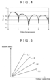
- the filter characteristic shown in FIG. 4 is an example of a filter characteristic with which to extract the 0.5 order of engine speed, and as long as the 0.5 order can be extracted, the filter processing according to this embodiment may be performed using a filter having a different filter characteristic to the filter characteristic shown in FIG. 4 .
- a method described in Japanese Patent Application Publication No. 7-119536 JP 7-119536 A ) may be cited as an example of a method implemented to extract the 0.5 order from the output signal of the crank angle sensor 4.
- FIG. 6 shows a comparison between a course L5 of the crank angle velocity of the crankshaft of the internal combustion engine 1 and a course L6 of an in-cylinder pressure. Both courses are shown along a common temporal axis.
- the compression end pressure is defined as the in-cylinder pressure when a piston disposed in the cylinder passes compression TDC.
- the compression end pressure is an element that determines a maximum value of a reaction force applied to rotation of the crankshaft.
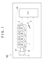
- the misfire detection system for the internal combustion engine 1 employs a configuration in which the correction unit 22 performs a correction in relation to the misfire detection performed by the misfire detection unit 23 using the misfire index.
- the corrected misfire index Nmf1 is calculated by multiplying a correction coefficient Ch associated with the value of the compression end pressure by the uncorrected misfire index derived by the misfire index derivation unit 21 in accordance with Equation 2, shown below.
- the correction coefficient Ch is set to decrease in value as the compression end pressure increases. More specifically, a compression end pressure appearing in the cylinders 2 of the internal combustion engine 1 is set as a reference pressure P0, and the correction coefficient at that time is set at 1.0.
- the correction coefficient Ch may be set as a function of the engine rotation speed and engine output (fuel injection amount) of the internal combustion engine 1. In so doing, the correction coefficient Ch can be derived while taking into consideration the correlation between the compression end pressure and the engine rotation speed and engine output (fuel injection amount), which can be measured in advance by experiment.
- a rotating mass (an inertia) based on the crankshaft of the internal combustion engine 1 may also be used to set the correction coefficient Ch.
- the misfire index correlates with the amount of variation in the angular velocity of the crankshaft, but in addition to the aforesaid compression end pressure, the rotating mass may be cited as another environmental condition to be taken into consideration. The reason for this is that when the rotating mass varies, the amount of variation in the angular velocity of the crankshaft may also vary, even if the compression end pressure remains constant. An inertial force typically increases as the rotating mass increases, and as a result, the amount of variation in the angular velocity of the crankshaft may decrease, leading to a reduction in the effect on the misfire index.
- the correction coefficient Ch set on the basis of the compression end pressure may be adjusted so as to increase as the rotating mass increases.
- the corrections relating to misfire detection described above are examples of correction using the compression end pressure, but instead of correcting the misfire index using the compression end pressure directly, the misfire index may be corrected using another pressure value, for example a turbocharged pressure P10 described below, as a parameter relating to the compression end pressure.
- a turbocharged pressure P10 described below
- a line L8 in FIG. 9 shows a course of the pressure in the cylinder 2.
- a pressure indicated by a point P10 before compression TDC is a pressure generated at a point where the intake stroke occurs in the cylinder 2 such that the turbocharged intake air flows into the cylinder, and this pressure may be considered identical to the turbocharged pressure detected by the pressure sensor 12.
- fuel is injected from the fuel injection valve 3 in the vicinity of compression TDC, whereby the pressure in the cylinder 2 reaches a compression end pressure P13 and then rises to a peak pressure as the fuel is burned.
- Equation 3 corresponds to the aforesaid correlation between the turbocharged pressure P10 and the compression end pressure P13, and by using this correlation, the misfire index can be corrected on the basis of the turbocharged pressure P10.
- the misfire index may be corrected on the basis of this pressure P11.
- the uncorrected misfire index Nmf is corrected by the correction unit 22, whereby the corrected misfire index Nmf1 is calculated.
- Any of the correction examples described above may be used in the correction performed by the correction unit 22, but in this embodiment, it is assumed that a correction using the correction coefficient Ch shown in the second correction example, or in other words a correction performed in accordance with Equation 2, is performed. More specifically, as shown in FIG. 7 , a control map on which a correlation between the compression end pressure Ptdc and the correction coefficient Ch is set such that the correction coefficient Ch decreases, or in other words a correction amount applied to the uncorrected misfire index Nmf increases, as the compression end pressure Ptdc increases is stored in the ECU 20.
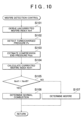
- the corrected misfire index Nmf1 is calculated in S104 after estimating the compression end pressure Ptdc in S103, but instead of this configuration, the corrected misfire index Nmf1 may be calculated on the basis of the turbocharged pressure Ps detected in S102. In this case, as described above, the corrected misfire index Nmf1 is calculated in consideration of the correlation between the turbocharged pressure Ps and the compression end pressure Ptdc shown in Equation 3. More specifically, the correction coefficient Ch used to calculate the corrected misfire index Nmf1.
- the correlation between the correction coefficient Ch and the turbocharged pressure Ps is set on a control map such that the correction coefficient Ch decreases as a resulting converted value increases when the turbocharged pressure Ps is converted into the compression end pressure in consideration of the correlation.
- the correlation between the correction coefficient Ch and the turbocharged pressure Ps is set on a control map such that a correction amount applied to the uncorrected misfire index Nmf increases.
- the corrected misfire index Nmf1 is calculated in S104 on the basis of the compression end pressure Ptdc, but instead of this configuration, the predetermined threshold Nmf0 may be corrected on the basis of the compression end pressure Ptdc, and the misfire determination may be performed by comparing the corrected predetermined threshold Nmf0 with the uncorrected misfire index Nmf.
- the predetermined threshold Nmf0 is corrected such that a correction amount (an increase amount) applied to the predetermined threshold Nmf0 increases as the compression end pressure Ptdc increases.
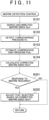
- a second embodiment of the misfire detection control executed in the misfire detection system for an internal combustion engine according to the invention will be described on the basis of FIG. 11 .
- the misfire detection control shown in FIG. 11 is performed by executing a control program stored in the ECU 20.
- identical processing to the processing included in the misfire detection control shown in FIG. 10 has been allocated identical reference symbols, and detailed description thereof has been omitted.
- the control advances to S201.
- control parameters relating to fuel injection in the internal combustion engine 1 are corrected on the basis of the corrected misfire index Nmf1.
- the corrected misfire index Nmf1 is an index from which the effect of the compression end pressure in the cylinder on the misfire index has been removed as far as possible, and therefore the value of the corrected misfire index Nmf1 is useful as a numerical value that precisely reflects the combustion condition in the cylinder 2.
- the control parameters relating to fuel injection are adjusted such that a favorable combustion condition is realized in the cylinder 2, or in other words such that the value of the misfire index decreases.
- a misfire condition in the internal combustion engine 1 can be alleviated by moving the injection timing of the pilot injection further toward the compression TDC side as the corrected misfire index Nmf1 increases.
- a fuel injection amount ratio between the pilot injection and the main injection is also preferably adjusted appropriately such that the misfire index decreases.
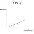
- the correction coefficient may be set such that a correlation between the torque variation and the corrected misfire index Nmf1 forms a linear relationship.
- variation in the value of the corrected misfire index Nmf1 is clearly associated with variation in an amount of torque variation in the internal combustion engine 1, and therefore the fuel injection timing of the pilot injection and the fuel injection amount ratio between the pilot injection and the main injection can be adjusted easily.
Landscapes
- Engineering & Computer Science (AREA)
- Chemical & Material Sciences (AREA)
- Combustion & Propulsion (AREA)
- Mechanical Engineering (AREA)
- General Engineering & Computer Science (AREA)
- Physics & Mathematics (AREA)
- General Physics & Mathematics (AREA)
- Combined Controls Of Internal Combustion Engines (AREA)
Claims (4)
- System zum Erkennen von Fehlzündungen für einen Verbrennungsmotor (1), wobei das System zum Erkennen von Fehlzündungen Folgendes umfasst:einen Kurbelwinkelsensor (4), der dafür konfiguriert ist, eine Drehwinkelposition einer Kurbelwelle des Verbrennungsmotors (1) zu erkennen,eine Einheit (23) zum Erkennen von Fehlzündungen, die dafür konfiguriert ist, basierend auf einem Fehlzündungsindex einen Fehlzündungszustand in dem Verbrennungsmotor (1) zu erkennen, wobei der Fehlzündungsindex von einer Drehzahl der Kurbelwelle als eine Referenz derart abgeleitet wird, dass er einer festgelegten Größenordnung der Motordrehzahl eines Ausgangssignals von dem Kurbelwinkelsensor (4) entspricht, und der eine Korrelation zu einem Umfang der Änderung in einer Winkelgeschwindigkeit der Kurbelwelle derart aufweist, dass sich ein Wert des Fehlzündungsindex gemäß dem Umfang der Änderung in der Winkelgeschwindigkeit der Kurbelwelle verändert,eine Erfassungseinheit, die dafür konfiguriert ist, einen Parameter bezüglich eines Verdichtungsenddrucks (Ptdc) in einem Zylinder (2) des Verbrennungsmotors (1) zu gewinnen, undeine Korrektureinheit (22), die dafür konfiguriert ist, den Fehlzündungsindex oder einen festgelegten Erkennungsparameter zum Erkennen von Fehlzündungen, der während des Erkennens einer Fehlzündung durch die Einheit (23) zum Erkennen von Fehlzündungen zusammen mit dem Fehlzündungsindex verwendet wird, basierend auf dem Parameter, der durch die Erfassungseinheit erzielt wird, zu korrigieren,wobei das System zum Erkennen von Fehlzündungen dadurch gekennzeichnet ist, dassder festgelegte Parameter zum Erkennen von Fehlzündungen ein festgelegter Schwellwert bezüglich des Fehlzündungsindex ist, der durch die Einheit (23) zum Erkennen von Fehlzündungen verwendet wird, um zu bestimmen, ob eine Fehlzündung aufgetreten ist oder nicht,wobei die Einheit (23) zum Erkennen von Fehlzündungen dafür konfiguriert ist, die Fehlzündung zu erkennen, wenn der Fehlzündungsindex größer als der festgelegte Schwellwert ist, unddie Korrektureinheit (22) dafür konfiguriert ist, den Fehlzündungsindex derart zu korrigieren, dass, wenn der Wert des durch die Erfassungseinheit gewonnenen Parameters in den Verdichtungsenddruck (Ptdc) in dem Zylinder (2) umgewandelt wird, ein Umfang der Korrektur, der auf den Fehlzündungsindex oder den festgelegten Schwellwert anzuwenden ist, größer wird, wenn ein resultierender umgewandelter Wert größer wird.
- System zum Erkennen von Fehlzündungen nach Anspruch 1, wobeider Verbrennungsmotor (1) einen Turbolader (11) beinhaltet undder Parameter ein Ladedruck ist, der durch den Turbolader (11) erzeugt wird.
- System zum Erkennen von Fehlzündungen nach einem der Ansprüche 1 und 2, wobeider Verbrennungsmotor (1) einen Turbolader (11) beinhaltet undder Parameter der Verdichtungsenddruck (Ptdc) in dem Zylinder (2) ist, der auf der Basis eines vom Turbolader (11) erzeugten Ladedrucks geschätzt wird.
- System zum Erkennen von Fehlzündungen nach Anspruch 2 oder 3, wobei der Parameter der Verdichtungsenddruck (Ptdc) ist, der auf der Basis des Ladedrucks unter einer Annahme geschätzt wird, dass am oberen Totpunkt der Verdichtung in dem Zylinder (2) kein Kraftstoff verbrannt wird.
Applications Claiming Priority (2)
| Application Number | Priority Date | Filing Date | Title |
|---|---|---|---|
| JP2013119121A JP6032136B2 (ja) | 2013-06-05 | 2013-06-05 | 内燃機関の失火検出システム |
| PCT/IB2014/000971 WO2014195791A1 (en) | 2013-06-05 | 2014-06-05 | Misfire detection system for internal combustion engine |
Publications (2)
| Publication Number | Publication Date |
|---|---|
| EP3004604A1 EP3004604A1 (de) | 2016-04-13 |
| EP3004604B1 true EP3004604B1 (de) | 2025-03-12 |
Family
ID=51022361
Family Applications (1)
| Application Number | Title | Priority Date | Filing Date |
|---|---|---|---|
| EP14733308.2A Active EP3004604B1 (de) | 2013-06-05 | 2014-06-05 | Fehlzündungsdetektor für einen verbrennungsmotor |
Country Status (7)
| Country | Link |
|---|---|
| EP (1) | EP3004604B1 (de) |
| JP (1) | JP6032136B2 (de) |
| CN (1) | CN105264204B (de) |
| AU (1) | AU2014276543B2 (de) |
| BR (1) | BR112015030156B1 (de) |
| RU (1) | RU2636283C2 (de) |
| WO (1) | WO2014195791A1 (de) |
Families Citing this family (27)
| Publication number | Priority date | Publication date | Assignee | Title |
|---|---|---|---|---|
| US9631566B1 (en) * | 2015-10-27 | 2017-04-25 | Caterpillar Inc. | Pre-chamber fuel admission valve diagnostics |
| JP6350591B2 (ja) * | 2016-05-17 | 2018-07-04 | トヨタ自動車株式会社 | 内燃機関の制御装置 |
| JP6550408B2 (ja) | 2017-02-08 | 2019-07-24 | 三菱重工エンジン&ターボチャージャ株式会社 | エンジンの失火検出装置及び方法 |
| JP6536601B2 (ja) * | 2017-02-28 | 2019-07-03 | トヨタ自動車株式会社 | 内燃機関の失火検出装置 |
| CN109269810A (zh) * | 2017-07-17 | 2019-01-25 | 山东交通学院 | 一种基于质心广义力识别的发动机失火故障诊断方法 |
| EP3524805B1 (de) | 2017-12-27 | 2021-02-17 | Mitsubishi Heavy Industries Engine & Turbocharger, Ltd. | Vorrichtung zur erkennung von motoranomalien |
| JP6522187B1 (ja) * | 2018-03-13 | 2019-05-29 | 愛三工業株式会社 | エンジンシステム |
| KR101891477B1 (ko) * | 2018-04-23 | 2018-09-28 | 정균식 | 대형 저속 엔진의 연소분석장치 및 이를 이용한 엔진의 연소상태 판단방법 |
| KR101865023B1 (ko) * | 2018-04-23 | 2018-06-07 | 정균식 | 대형 저속 2행정 엔진의 출력측정시스템 및 출력측정방법 |
| US10983029B2 (en) * | 2018-10-08 | 2021-04-20 | GM Global Technology Operations LLC | Engine misfire detection |
| KR102119872B1 (ko) * | 2018-12-04 | 2020-06-05 | 현대오트론 주식회사 | 단기통 4행정 엔진의 실화 진단 방법 및 시스템 |
| KR102119873B1 (ko) * | 2018-12-04 | 2020-06-05 | 현대오트론 주식회사 | 단기통 4행정 엔진의 실화 진단 방법 및 장치 |
| KR102119876B1 (ko) * | 2018-12-04 | 2020-06-05 | 현대오트론 주식회사 | 단기통 4행정 엔진의 실화 진단 방법 및 장치 |
| JP6593560B1 (ja) * | 2019-02-15 | 2019-10-23 | トヨタ自動車株式会社 | 内燃機関の失火検出装置、内燃機関の失火検出システム、データ解析装置、および内燃機関の制御装置 |
| KR102119852B1 (ko) * | 2019-04-02 | 2020-06-05 | 현대오트론 주식회사 | 단기통 4행정 엔진의 실화 진단 방법 및 장치 |
| KR102119865B1 (ko) * | 2019-04-02 | 2020-06-05 | 현대오트론 주식회사 | 단기통 4행정 엔진의 실화 진단 방법 및 장치 |
| CN112113771B (zh) * | 2019-06-21 | 2023-01-06 | 联合汽车电子有限公司 | 失火信号的测量方法及测量系统 |
| KR102131713B1 (ko) * | 2019-07-25 | 2020-07-08 | 현대오트론 주식회사 | 다기통 엔진의 실화 진단 방법 및 장치 |
| KR102153484B1 (ko) * | 2019-07-25 | 2020-09-08 | 현대오트론 주식회사 | 다기통 엔진의 실화 진단 방법 및 장치 |
| JP6705539B1 (ja) * | 2019-08-22 | 2020-06-03 | トヨタ自動車株式会社 | 失火検出装置、失火検出システムおよびデータ解析装置 |
| CN111365147B (zh) * | 2020-03-19 | 2021-08-03 | 江苏奥易克斯汽车电子科技股份有限公司 | 废气再循环系统流量判断方法 |
| CN111779572B (zh) * | 2020-06-24 | 2021-07-27 | 中国第一汽车股份有限公司 | 一种失火诊断方法、装置、设备及存储介质 |
| CN112360640B (zh) * | 2020-10-15 | 2023-01-24 | 潍柴动力股份有限公司 | 发动机失火的监控方法、装置及系统 |
| JP7392672B2 (ja) * | 2021-01-29 | 2023-12-06 | トヨタ自動車株式会社 | 内燃機関の失火検出装置 |
| JP7737820B2 (ja) | 2021-06-03 | 2025-09-11 | 三菱重工エンジン&ターボチャージャ株式会社 | 内燃機関の失火検知装置、および、失火検知方法 |
| CN115263548B (zh) * | 2022-04-02 | 2024-08-27 | 长城汽车股份有限公司 | 一种发动机失火检测方法、装置、车辆和存储介质 |
| CN115855515B (zh) * | 2022-09-07 | 2025-09-19 | 潍柴动力股份有限公司 | 一种发动机失火检测方法及装置 |
Family Cites Families (14)
| Publication number | Priority date | Publication date | Assignee | Title |
|---|---|---|---|---|
| JPH05195858A (ja) * | 1991-11-08 | 1993-08-03 | Nippondenso Co Ltd | 多気筒内燃機関の失火検出装置 |
| JP2807738B2 (ja) * | 1993-10-15 | 1998-10-08 | 本田技研工業株式会社 | 内燃エンジンの燃焼状態検出装置 |
| JPH07119532A (ja) * | 1993-10-19 | 1995-05-09 | Unisia Jecs Corp | 内燃機関の失火検出装置 |
| JP3336811B2 (ja) * | 1995-04-19 | 2002-10-21 | 三菱自動車工業株式会社 | 内燃機関の燃焼状態判定装置および内燃機関の燃焼状態制御装置 |
| US6243641B1 (en) * | 1995-06-07 | 2001-06-05 | Cummins Engine Company, Inc. | System and method for detecting engine cylinder misfire |
| IT1298944B1 (it) * | 1998-02-24 | 2000-02-07 | Automobili Lamborghini Spa | Procedimento per rilevare il mancato scoppio in un motore a combustione interna e sistema che realizza tale procedimento |
| JP3958636B2 (ja) | 2002-02-28 | 2007-08-15 | 本田技研工業株式会社 | 車両用多気筒内燃機関の失火検出装置 |
| JP4525538B2 (ja) * | 2005-02-24 | 2010-08-18 | トヨタ自動車株式会社 | 内燃機関の失火判定装置および失火判定方法 |
| JP5026334B2 (ja) * | 2008-05-15 | 2012-09-12 | 三菱電機株式会社 | 角速度及び角加速度算出装置、トルク推定装置、燃焼状態推定装置 |
| JP5314464B2 (ja) * | 2009-03-12 | 2013-10-16 | 川崎重工業株式会社 | エンジン失火判定システム及び方法 |
| JP2011085081A (ja) * | 2009-10-16 | 2011-04-28 | Daihatsu Motor Co Ltd | エンジンの失火判定方法 |
| DE102009046961A1 (de) * | 2009-11-23 | 2011-05-26 | Robert Bosch Gmbh | Verfahren und Vorrichtung zur Erkennung von unkontrollierten Verbrennungen in einem Verbrennungsmotor |
| CN102667122B (zh) * | 2010-01-13 | 2015-04-29 | 本田技研工业株式会社 | 内燃机的失火检测装置 |
| JP5496004B2 (ja) | 2010-07-29 | 2014-05-21 | 三菱重工業株式会社 | エンジンの失火検出装置及び方法 |
-
2013
- 2013-06-05 JP JP2013119121A patent/JP6032136B2/ja not_active Expired - Fee Related
-
2014
- 2014-06-05 BR BR112015030156-8A patent/BR112015030156B1/pt not_active IP Right Cessation
- 2014-06-05 CN CN201480032328.XA patent/CN105264204B/zh not_active Expired - Fee Related
- 2014-06-05 RU RU2015151992A patent/RU2636283C2/ru active
- 2014-06-05 AU AU2014276543A patent/AU2014276543B2/en not_active Ceased
- 2014-06-05 WO PCT/IB2014/000971 patent/WO2014195791A1/en not_active Ceased
- 2014-06-05 EP EP14733308.2A patent/EP3004604B1/de active Active
Also Published As
| Publication number | Publication date |
|---|---|
| JP2014234814A (ja) | 2014-12-15 |
| RU2015151992A (ru) | 2017-07-20 |
| CN105264204B (zh) | 2018-03-30 |
| AU2014276543B2 (en) | 2017-02-09 |
| WO2014195791A1 (en) | 2014-12-11 |
| BR112015030156B1 (pt) | 2022-03-22 |
| EP3004604A1 (de) | 2016-04-13 |
| RU2636283C2 (ru) | 2017-11-21 |
| CN105264204A (zh) | 2016-01-20 |
| JP6032136B2 (ja) | 2016-11-24 |
| BR112015030156A2 (pt) | 2017-07-25 |
| AU2014276543A1 (en) | 2015-12-24 |
Similar Documents
| Publication | Publication Date | Title |
|---|---|---|
| AU2014276543B2 (en) | Misfire detection system for internal combustion engine | |
| US9857273B2 (en) | Misfire detecting apparatus for internal combustion engine | |
| US9765709B2 (en) | Control apparatus for determining an absolute pressure correction in an internal combustion engine | |
| EP2910760A1 (de) | Zylinderinterne druckmessvorrichtung für einen verbrennungsmotor | |
| US20180066593A1 (en) | Control Device for Internal Combustion Engine and Abnormal Combustion Detecting Method | |
| US8826886B2 (en) | Engine ignition timing setting apparatus | |
| US8744733B2 (en) | Control apparatus for internal combustion engine | |
| JP5331613B2 (ja) | 内燃機関の筒内ガス量推定装置 | |
| US8924134B2 (en) | Knock control device of internal combustion engine | |
| US20150219026A1 (en) | In-cylinder pressure detection device for internal combustion engine | |
| US20130192343A1 (en) | Knock detection device of internal combustion engine | |
| US20160348596A1 (en) | Ignition device and ignition method for internal combustion engine | |
| US20100031923A1 (en) | Method and Apparatus for Detecting Engine Knock | |
| JP2011157852A (ja) | 内燃機関の制御装置 | |
| JP2015158163A (ja) | 火花点火式内燃機関の制御装置 | |
| US12163858B2 (en) | Misfire determination device for internal combustion engine | |
| US20250092840A1 (en) | Pre-ignition determining apparatus for internal combustion engine | |
| JP2016156295A (ja) | 内燃機関の燃料噴射制御装置及び燃料噴射制御方法 | |
| JP2013155638A (ja) | 筒内圧センサの劣化検出装置 | |
| JP2016011596A (ja) | 内燃機関の燃焼圧検出方法及び燃焼圧検出装置 |
Legal Events
| Date | Code | Title | Description |
|---|---|---|---|
| PUAI | Public reference made under article 153(3) epc to a published international application that has entered the european phase |
Free format text: ORIGINAL CODE: 0009012 |
|
| 17P | Request for examination filed |
Effective date: 20151204 |
|
| AK | Designated contracting states |
Kind code of ref document: A1 Designated state(s): AL AT BE BG CH CY CZ DE DK EE ES FI FR GB GR HR HU IE IS IT LI LT LU LV MC MK MT NL NO PL PT RO RS SE SI SK SM TR |
|
| AX | Request for extension of the european patent |
Extension state: BA ME |
|
| DAX | Request for extension of the european patent (deleted) | ||
| STAA | Information on the status of an ep patent application or granted ep patent |
Free format text: STATUS: EXAMINATION IS IN PROGRESS |
|
| 17Q | First examination report despatched |
Effective date: 20210326 |
|
| RIC1 | Information provided on ipc code assigned before grant |
Ipc: G01M 15/11 20060101ALI20240823BHEP Ipc: F02D 41/14 20060101ALI20240823BHEP Ipc: F02D 35/02 20060101AFI20240823BHEP |
|
| GRAP | Despatch of communication of intention to grant a patent |
Free format text: ORIGINAL CODE: EPIDOSNIGR1 |
|
| STAA | Information on the status of an ep patent application or granted ep patent |
Free format text: STATUS: GRANT OF PATENT IS INTENDED |
|
| INTG | Intention to grant announced |
Effective date: 20241004 |
|
| GRAS | Grant fee paid |
Free format text: ORIGINAL CODE: EPIDOSNIGR3 |
|
| GRAA | (expected) grant |
Free format text: ORIGINAL CODE: 0009210 |
|
| STAA | Information on the status of an ep patent application or granted ep patent |
Free format text: STATUS: THE PATENT HAS BEEN GRANTED |
|
| AK | Designated contracting states |
Kind code of ref document: B1 Designated state(s): AL AT BE BG CH CY CZ DE DK EE ES FI FR GB GR HR HU IE IS IT LI LT LU LV MC MK MT NL NO PL PT RO RS SE SI SK SM TR |
|
| REG | Reference to a national code |
Ref country code: GB Ref legal event code: FG4D |
|
| REG | Reference to a national code |
Ref country code: CH Ref legal event code: EP |
|
| REG | Reference to a national code |
Ref country code: DE Ref legal event code: R096 Ref document number: 602014091667 Country of ref document: DE |
|
| REG | Reference to a national code |
Ref country code: IE Ref legal event code: FG4D |
|
| P01 | Opt-out of the competence of the unified patent court (upc) registered |
Free format text: CASE NUMBER: APP_20535/2025 Effective date: 20250430 |
|
| PG25 | Lapsed in a contracting state [announced via postgrant information from national office to epo] |
Ref country code: RS Free format text: LAPSE BECAUSE OF FAILURE TO SUBMIT A TRANSLATION OF THE DESCRIPTION OR TO PAY THE FEE WITHIN THE PRESCRIBED TIME-LIMIT Effective date: 20250612 |
|
| PG25 | Lapsed in a contracting state [announced via postgrant information from national office to epo] |
Ref country code: FI Free format text: LAPSE BECAUSE OF FAILURE TO SUBMIT A TRANSLATION OF THE DESCRIPTION OR TO PAY THE FEE WITHIN THE PRESCRIBED TIME-LIMIT Effective date: 20250312 |
|
| PGFP | Annual fee paid to national office [announced via postgrant information from national office to epo] |
Ref country code: DE Payment date: 20250429 Year of fee payment: 12 |
|
| PG25 | Lapsed in a contracting state [announced via postgrant information from national office to epo] |
Ref country code: ES Free format text: LAPSE BECAUSE OF FAILURE TO SUBMIT A TRANSLATION OF THE DESCRIPTION OR TO PAY THE FEE WITHIN THE PRESCRIBED TIME-LIMIT Effective date: 20250312 |
|
| REG | Reference to a national code |
Ref country code: LT Ref legal event code: MG9D |
|
| PG25 | Lapsed in a contracting state [announced via postgrant information from national office to epo] |
Ref country code: NO Free format text: LAPSE BECAUSE OF FAILURE TO SUBMIT A TRANSLATION OF THE DESCRIPTION OR TO PAY THE FEE WITHIN THE PRESCRIBED TIME-LIMIT Effective date: 20250612 |
|
| PG25 | Lapsed in a contracting state [announced via postgrant information from national office to epo] |
Ref country code: HR Free format text: LAPSE BECAUSE OF FAILURE TO SUBMIT A TRANSLATION OF THE DESCRIPTION OR TO PAY THE FEE WITHIN THE PRESCRIBED TIME-LIMIT Effective date: 20250312 |
|
| REG | Reference to a national code |
Ref country code: NL Ref legal event code: MP Effective date: 20250312 |
|
| PG25 | Lapsed in a contracting state [announced via postgrant information from national office to epo] |
Ref country code: LV Free format text: LAPSE BECAUSE OF FAILURE TO SUBMIT A TRANSLATION OF THE DESCRIPTION OR TO PAY THE FEE WITHIN THE PRESCRIBED TIME-LIMIT Effective date: 20250312 |
|
| PGFP | Annual fee paid to national office [announced via postgrant information from national office to epo] |
Ref country code: FR Payment date: 20250508 Year of fee payment: 12 |
|
| PG25 | Lapsed in a contracting state [announced via postgrant information from national office to epo] |
Ref country code: BG Free format text: LAPSE BECAUSE OF FAILURE TO SUBMIT A TRANSLATION OF THE DESCRIPTION OR TO PAY THE FEE WITHIN THE PRESCRIBED TIME-LIMIT Effective date: 20250312 Ref country code: GR Free format text: LAPSE BECAUSE OF FAILURE TO SUBMIT A TRANSLATION OF THE DESCRIPTION OR TO PAY THE FEE WITHIN THE PRESCRIBED TIME-LIMIT Effective date: 20250613 |
|
| REG | Reference to a national code |
Ref country code: AT Ref legal event code: MK05 Ref document number: 1775167 Country of ref document: AT Kind code of ref document: T Effective date: 20250312 |
|
| PG25 | Lapsed in a contracting state [announced via postgrant information from national office to epo] |
Ref country code: NL Free format text: LAPSE BECAUSE OF FAILURE TO SUBMIT A TRANSLATION OF THE DESCRIPTION OR TO PAY THE FEE WITHIN THE PRESCRIBED TIME-LIMIT Effective date: 20250312 |
|
| PG25 | Lapsed in a contracting state [announced via postgrant information from national office to epo] |
Ref country code: SE Free format text: LAPSE BECAUSE OF FAILURE TO SUBMIT A TRANSLATION OF THE DESCRIPTION OR TO PAY THE FEE WITHIN THE PRESCRIBED TIME-LIMIT Effective date: 20250312 |
|
| REG | Reference to a national code |
Ref country code: DE Ref legal event code: R084 Ref document number: 602014091667 Country of ref document: DE |
|
| PG25 | Lapsed in a contracting state [announced via postgrant information from national office to epo] |
Ref country code: SM Free format text: LAPSE BECAUSE OF FAILURE TO SUBMIT A TRANSLATION OF THE DESCRIPTION OR TO PAY THE FEE WITHIN THE PRESCRIBED TIME-LIMIT Effective date: 20250312 |
|
| PG25 | Lapsed in a contracting state [announced via postgrant information from national office to epo] |
Ref country code: PT Free format text: LAPSE BECAUSE OF FAILURE TO SUBMIT A TRANSLATION OF THE DESCRIPTION OR TO PAY THE FEE WITHIN THE PRESCRIBED TIME-LIMIT Effective date: 20250714 |
|
| PG25 | Lapsed in a contracting state [announced via postgrant information from national office to epo] |
Ref country code: PL Free format text: LAPSE BECAUSE OF FAILURE TO SUBMIT A TRANSLATION OF THE DESCRIPTION OR TO PAY THE FEE WITHIN THE PRESCRIBED TIME-LIMIT Effective date: 20250312 Ref country code: IT Free format text: LAPSE BECAUSE OF FAILURE TO SUBMIT A TRANSLATION OF THE DESCRIPTION OR TO PAY THE FEE WITHIN THE PRESCRIBED TIME-LIMIT Effective date: 20250312 |
|
| PG25 | Lapsed in a contracting state [announced via postgrant information from national office to epo] |
Ref country code: AT Free format text: LAPSE BECAUSE OF FAILURE TO SUBMIT A TRANSLATION OF THE DESCRIPTION OR TO PAY THE FEE WITHIN THE PRESCRIBED TIME-LIMIT Effective date: 20250312 |
|
| PG25 | Lapsed in a contracting state [announced via postgrant information from national office to epo] |
Ref country code: CZ Free format text: LAPSE BECAUSE OF FAILURE TO SUBMIT A TRANSLATION OF THE DESCRIPTION OR TO PAY THE FEE WITHIN THE PRESCRIBED TIME-LIMIT Effective date: 20250312 Ref country code: EE Free format text: LAPSE BECAUSE OF FAILURE TO SUBMIT A TRANSLATION OF THE DESCRIPTION OR TO PAY THE FEE WITHIN THE PRESCRIBED TIME-LIMIT Effective date: 20250312 |
|
| PG25 | Lapsed in a contracting state [announced via postgrant information from national office to epo] |
Ref country code: RO Free format text: LAPSE BECAUSE OF FAILURE TO SUBMIT A TRANSLATION OF THE DESCRIPTION OR TO PAY THE FEE WITHIN THE PRESCRIBED TIME-LIMIT Effective date: 20250312 |
|
| PG25 | Lapsed in a contracting state [announced via postgrant information from national office to epo] |
Ref country code: SK Free format text: LAPSE BECAUSE OF FAILURE TO SUBMIT A TRANSLATION OF THE DESCRIPTION OR TO PAY THE FEE WITHIN THE PRESCRIBED TIME-LIMIT Effective date: 20250312 |
|
| PG25 | Lapsed in a contracting state [announced via postgrant information from national office to epo] |
Ref country code: IS Free format text: LAPSE BECAUSE OF FAILURE TO SUBMIT A TRANSLATION OF THE DESCRIPTION OR TO PAY THE FEE WITHIN THE PRESCRIBED TIME-LIMIT Effective date: 20250712 |
|
| REG | Reference to a national code |
Ref country code: DE Ref legal event code: R097 Ref document number: 602014091667 Country of ref document: DE |
|
| PG25 | Lapsed in a contracting state [announced via postgrant information from national office to epo] |
Ref country code: DK Free format text: LAPSE BECAUSE OF FAILURE TO SUBMIT A TRANSLATION OF THE DESCRIPTION OR TO PAY THE FEE WITHIN THE PRESCRIBED TIME-LIMIT Effective date: 20250312 |
|
| PLBE | No opposition filed within time limit |
Free format text: ORIGINAL CODE: 0009261 |
|
| STAA | Information on the status of an ep patent application or granted ep patent |
Free format text: STATUS: NO OPPOSITION FILED WITHIN TIME LIMIT |
|
| REG | Reference to a national code |
Ref country code: CH Ref legal event code: L10 Free format text: ST27 STATUS EVENT CODE: U-0-0-L10-L00 (AS PROVIDED BY THE NATIONAL OFFICE) Effective date: 20260121 |
|
| REG | Reference to a national code |
Ref country code: CH Ref legal event code: H13 Free format text: ST27 STATUS EVENT CODE: U-0-0-H10-H13 (AS PROVIDED BY THE NATIONAL OFFICE) Effective date: 20260127 |
|
| PG25 | Lapsed in a contracting state [announced via postgrant information from national office to epo] |
Ref country code: MC Free format text: LAPSE BECAUSE OF FAILURE TO SUBMIT A TRANSLATION OF THE DESCRIPTION OR TO PAY THE FEE WITHIN THE PRESCRIBED TIME-LIMIT Effective date: 20250312 |
|
| PG25 | Lapsed in a contracting state [announced via postgrant information from national office to epo] |
Ref country code: LU Free format text: LAPSE BECAUSE OF NON-PAYMENT OF DUE FEES Effective date: 20250605 |
|
| 26N | No opposition filed |
Effective date: 20251215 |
|
| GBPC | Gb: european patent ceased through non-payment of renewal fee |
Effective date: 20250612 |
|
| REG | Reference to a national code |
Ref country code: BE Ref legal event code: MM Effective date: 20250630 |
|
| PG25 | Lapsed in a contracting state [announced via postgrant information from national office to epo] |
Ref country code: GB Free format text: LAPSE BECAUSE OF NON-PAYMENT OF DUE FEES Effective date: 20250612 |
|
| PG25 | Lapsed in a contracting state [announced via postgrant information from national office to epo] |
Ref country code: IE Free format text: LAPSE BECAUSE OF NON-PAYMENT OF DUE FEES Effective date: 20250605 |
|
| PG25 | Lapsed in a contracting state [announced via postgrant information from national office to epo] |
Ref country code: BE Free format text: LAPSE BECAUSE OF NON-PAYMENT OF DUE FEES Effective date: 20250630 |
|
| PG25 | Lapsed in a contracting state [announced via postgrant information from national office to epo] |
Ref country code: CH Free format text: LAPSE BECAUSE OF NON-PAYMENT OF DUE FEES Effective date: 20250630 |