EP3003584B1 - Portalvorrichtung zur abschirmung des innenraums eines anlagengehäuses - Google Patents
Portalvorrichtung zur abschirmung des innenraums eines anlagengehäuses Download PDFInfo
- Publication number
- EP3003584B1 EP3003584B1 EP14728961.5A EP14728961A EP3003584B1 EP 3003584 B1 EP3003584 B1 EP 3003584B1 EP 14728961 A EP14728961 A EP 14728961A EP 3003584 B1 EP3003584 B1 EP 3003584B1
- Authority
- EP
- European Patent Office
- Prior art keywords
- vertical
- horizontal
- housing
- slotted guides
- strand
- Prior art date
- Legal status (The legal status is an assumption and is not a legal conclusion. Google has not performed a legal analysis and makes no representation as to the accuracy of the status listed.)
- Not-in-force
Links
- 239000000463 material Substances 0.000 claims description 38
- 238000009434 installation Methods 0.000 claims 6
- 238000005096 rolling process Methods 0.000 claims 1
- 230000005855 radiation Effects 0.000 description 7
- 239000000109 continuous material Substances 0.000 description 2
- 238000012423 maintenance Methods 0.000 description 2
- 238000004519 manufacturing process Methods 0.000 description 2
- 230000000035 biogenic effect Effects 0.000 description 1
- 230000003750 conditioning effect Effects 0.000 description 1
- 230000007797 corrosion Effects 0.000 description 1
- 238000005260 corrosion Methods 0.000 description 1
- 230000001627 detrimental effect Effects 0.000 description 1
- 239000000428 dust Substances 0.000 description 1
- 239000003344 environmental pollutant Substances 0.000 description 1
- 239000000835 fiber Substances 0.000 description 1
- 231100000719 pollutant Toxicity 0.000 description 1
- 230000032258 transport Effects 0.000 description 1
Images


Classifications
-
- B—PERFORMING OPERATIONS; TRANSPORTING
- B08—CLEANING
- B08B—CLEANING IN GENERAL; PREVENTION OF FOULING IN GENERAL
- B08B15/00—Preventing escape of dirt or fumes from the area where they are produced; Collecting or removing dirt or fumes from that area
- B08B15/02—Preventing escape of dirt or fumes from the area where they are produced; Collecting or removing dirt or fumes from that area using chambers or hoods covering the area
-
- F—MECHANICAL ENGINEERING; LIGHTING; HEATING; WEAPONS; BLASTING
- F16—ENGINEERING ELEMENTS AND UNITS; GENERAL MEASURES FOR PRODUCING AND MAINTAINING EFFECTIVE FUNCTIONING OF MACHINES OR INSTALLATIONS; THERMAL INSULATION IN GENERAL
- F16J—PISTONS; CYLINDERS; SEALINGS
- F16J15/00—Sealings
- F16J15/16—Sealings between relatively-moving surfaces
- F16J15/168—Sealings between relatively-moving surfaces which permits material to be continuously conveyed
-
- H—ELECTRICITY
- H05—ELECTRIC TECHNIQUES NOT OTHERWISE PROVIDED FOR
- H05B—ELECTRIC HEATING; ELECTRIC LIGHT SOURCES NOT OTHERWISE PROVIDED FOR; CIRCUIT ARRANGEMENTS FOR ELECTRIC LIGHT SOURCES, IN GENERAL
- H05B6/00—Heating by electric, magnetic or electromagnetic fields
- H05B6/64—Heating using microwaves
- H05B6/76—Prevention of microwave leakage, e.g. door sealings
-
- H—ELECTRICITY
- H05—ELECTRIC TECHNIQUES NOT OTHERWISE PROVIDED FOR
- H05B—ELECTRIC HEATING; ELECTRIC LIGHT SOURCES NOT OTHERWISE PROVIDED FOR; CIRCUIT ARRANGEMENTS FOR ELECTRIC LIGHT SOURCES, IN GENERAL
- H05B6/00—Heating by electric, magnetic or electromagnetic fields
- H05B6/64—Heating using microwaves
- H05B6/78—Arrangements for continuous movement of material
Definitions
- the invention relates to a gantry device according to claim 1.
- the document DE-A-1565802 discloses a gantry device according to the prior art.
- exit or inlet openings for a continuous continuous strand of material are required, these are integrated as required by the emissions to be shielded directly into the corresponding housing walls. Furthermore, such outlets or inlets are adapted to uniform strands of material and are not able to respond to changes in the material strand geometry. In particular, simultaneous height and width changes are not provided.
- Object of the present invention is therefore to design a gantry device so that it can be attached as a complete assembly to an existing equipment housing.
- the gantry device should be able to respond to different material strand geometries, especially if their input and / or outlet production is not always in the same place.
- a gantry device has the combination of features according to claim 1.
- Such a trained portal device can be easily adapted depending on the requirements for shielding the emissions occurring in the system housing, both in terms of vertical and horizontal offsets, as well as their storage, and in particular as an assembly are then attached to the system housing.
- the cross member and the side rails should be designed as a U-box-shaped housing, between whose walls the vertical and the horizontal frames are guided.
- This embodiment not only has the advantage of ensuring an accurate guidance of the scenes, since the slotted guide from external influences that can cause corrosion, for example, are protected, but beyond the advantage that the U-shaped housing easily attachable to a wall ofenfinstattenden investment housing is.
- the material of the housing of the portal device as well as the scenes for the emissions to be shielded can be impermeable.
- this is microwave-impermeable material to shield microwave radiation emanating from a radiation source inside the equipment housing.
- a preferred embodiment of the portal device according to the invention has as actuators rack drives with servo motors. This proven actuator design ensures high reliability and robustness. However, it is alternatively also possible to use hydraulic actuators.
- the gantry device can also be provided in particular to prevent the entry of (faulty) air or other pollutants from the environment.
- the present invention is capable of reducing or increasing the ingress of false air from the outside along the strand of material avoid and in particular disturbances of the material strand by high relative velocities of (entering through the negative pressure) in the plant housing air to avoid the material strand along.
- replacement openings are provided, which can be acted upon in particular with a corresponding desired supply air and are connected to the interior of the system housing such that the relative speed between possible leaks between the portal device and the material strand is not detrimental to the Impact material strand itself.
- a material strand 50 is to be treated, inter alia by means of a microwave oven 70.
- the direction of passage of the material strand 50 is indicated by D.
- the microwave oven continuously operating press 100 may be arranged, which cures a heated by the microwave oven 70 strand of material 50, preferably made of fibers, chips or other biogenic mass, by means of pressure and heat.
- the processing plant 80 is enclosed in this first exemplary embodiment by a plant housing 60 which only permits entry or exit of the material strand 50 by the portal devices 1, 40.
- the plant housing 60 has in this case essentially the task of shielding the microwave radiation, which emerges from the microwave oven 70, from the environment.
- the plant housing 60 can primarily serve to retain the residual radiation which emerges from such a microwave oven 70 despite shielding, for example through the inlet and outlet locks. This may be necessary in such systems to comply with necessary limits to the environment.
- the system housing 60 can function as a suction hood, wherein exhaust emissions via an exhaust device 81 corresponding to the processing plant contained therein, here the continuously operating press 100, to clean them in accordance with the emission regulations. It may further be provided to substitute the exhaust air by a supply air device 82. Nevertheless, in this case, a certain negative pressure in the system housing 60 will be necessary to guide the air flow from the supply air device 82 to the exhaust device 81.
- the portal devices 1, 40 it may also be necessary to shield the inlet and outlet of the material strand by means of the portal devices 1, 40, in order not to introduce any incorrect air from the environment into the plant housing. Even if the portal devices 1, 40 can not hermetically seal, it is still possible to control air flows in the system housing 60 more efficiently.
- the material strand 50 can be guided on the inlet and outlet side, depending on the nature of the material strand 50, with a conveyor belt 90.
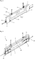
- the gantry device 1 comprises an upper cross member 2, at the ends of which U-shaped side rails 3, 4 connect.
- the free ends of the side rails 3, 4 are connected to a table rail 5.
- This table rail 5 serves as a stop or support for a strand of material 50 respectively a transporting conveyor belt 90, which runs through the portal device 1 in the interior of the system housing 60 and exits at the other end of the system housing 60 through the portal device 40 again.
- Cross member 2 and side rails 3, 4 are formed as a U-box-shaped housing with a front cover wall 12 and a rear cover wall 11 (FIG. FIG. 3 ). Between these walls a vertical slide 21 and a right horizontal slide 31 and a left horizontal slide 41 are mounted. In the front cover wall 12 maintenance cover 14 are provided which allow access to the elements located inside the housing.
- FIG. 3 Details of storage are off Fig. 3 recognizable, which corresponds to a representation Fig. 2 , but with the top wall 12 removed.
- the vertical slide 21 is moved by means of the vertical actuators 25, which may be formed in the embodiment shown as rack drives with racks and servomotors.
- the movement of the horizontal slits 31, 41 is carried out in the illustrated embodiment by means of a rack drives horizontal actuators 35, 45. Instead of the rack drives and corresponding hydraulic actuators could be provided.
- the horizontal slits 31, 41 are independently of each other and independently of the vertical slide 21 displaceable and the actuators 35, 45 and 25 are independently controllable.
- a control device necessary for this purpose which preferably have vertical and horizontal sensors for scanning the thickness and the width of the material strand 50, may be attached to the gantry device 1, 40 itself, but may also be provided elsewhere in the plant housing 60 or in a corresponding control room his. In the drawings, the control system is omitted.
- FIGS. 4 In the front view after FIGS. 4 are the same parts with the same reference numerals as in the FIGS. 2 and 3 , To illustrate the operation of the portal device is in Fig. 4 a strand of material 50 cross-hatched drawn. It can be seen that the horizontal slits 31, 41 are moved up to a minimum movement gap (not shown) on the sides of the material strand 50. The vertical slide 21 is not yet in its end position in this view and forms a visible movement gap SP.
- a horizontally projecting support bracket 23 is attached, which protrudes counter to the direction of passage D of the portal device and may contain further shielding or measuring devices.
- the distance from the lower region 22 of the vertical frame or the material strand 50 is to be interpreted in accordance with the circumstances.
- a possible conveyor belt 90 is clearly visible, which transports the material strand 50 through or to the processing plant.
- the conveyor belt can pass undisturbed below the horizontal slits (cf. FIG. 4 ).
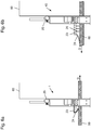
- FIG. 6a shows the portal device 1, as at the entrance of the plant housing 60 (see. Fig. 1 ) is provided.
- the side view after FIG. 6b shows the gantry device 40 at the outlet of the plant housing 60.
- the various embodiments are correspondingly also applicable and only by way of example. But is particularly advantageous if the support bracket relative to the system housing 60 is oriented outwards to the environment. This has the advantage that deposits on the support bracket, such as dust or the like., Can be easily cleaned and can not lead to incalculable problems within the system housing.
- a flexible trailing band 24 is clamped, which extends over the entire width of the support bracket 23.
- the trailing belt 24 is recognizable designed so that it on a continuous strand of material 50 allowing a relative movement, rests. Preferably, the surface of the material strand 50 should not be disturbed.
- a plurality of spaced-apart substantially vertically aligned and also over the entire width of the vertical slot 23 extending shielding plates 26 are attached to the underside of the support bracket 23. It can be seen that one is related to Fig. 6b , Coming from the interior of the system housing 60 microwave radiation is completely shielded by the Radiantablebleche 26 and the trailing belt 24.
Landscapes
- Engineering & Computer Science (AREA)
- General Engineering & Computer Science (AREA)
- Physics & Mathematics (AREA)
- Electromagnetism (AREA)
- Mechanical Engineering (AREA)
- Shielding Devices Or Components To Electric Or Magnetic Fields (AREA)
- Paper (AREA)
- Physical Or Chemical Processes And Apparatus (AREA)
- Vertical, Hearth, Or Arc Furnaces (AREA)
- Ventilation (AREA)
Description
- Die Erfindung bezieht sich auf eine Portalvorrichtung nach Patentanspruch 1.
- Das Dokument
DE-A-1565802 offenbart eine Portalvorrichtung gemäß dem Stand der Technik. - Soweit in vorbekannten Anlagengehäusen, die eine Verarbeitungsanlage umgeben, Aus- bzw. Eintrittsöffnungen für einen kontinuierlich durchlaufenden Materialstrang erforderlich sind, werden diese je nach Notwendigkeit der abzuschirmenden Emissionen unmittelbar in die entsprechenden Gehäusewände integriert. Weiter werden derartige Aus- bzw. Eintrittsöffnungen an gleichförmige Materialstränge angepasst und sind nicht in der Lage auf Veränderungen der Materialstranggeometrie zu reagieren. Insbesondere gleichzeitige Höhen und Breitenänderungen sind nicht vorgesehen.
- Aufgabe der vorliegenden Erfindung ist es deshalb, eine Portalvorrichtung so auszugestalten, dass sie als komplette Baugruppe an einem vorhandenen Anlagengehäuse befestigt werden kann. Insbesondere soll die Portalvorrichtung geeignet sein auf unterschiedliche Materialstranggeometrien reagieren zu können, insbesondere wenn deren Ein- und/oder Auslauf produktionsbedingt nicht immer an derselben Stelle ist.
- Erfindungsgemäß wird die gestellte Aufgabe dadurch gelöst, dass eine Portalvorrichtung die Merkmalskombination nach Patentanspruch 1 aufweist.
- Eine solcherart ausgebildete Portalvorrichtung kann je nach den gestellten Anforderungen zur Abschirmung der auftretenden Emissionen im Anlagengehäuse, sowohl was die Vertikal- und Horizontalkulissen anbelangt, als auch deren Lagerung betrifft, problemlos angepasst werden und insbesondere als Baugruppe dann an dem Anlagengehäuse befestigt werden.
- Nach der Erfindung sollen der Querholm und die Seitenholme als U-kastenförmiges Gehäuse ausgebildet sein, zwischen dessen Wänden die Vertikal- und die Horizontalkulissen geführt sind. Diese Ausführungsform hat nicht nur den Vorteil, eine exakte Führung der Kulissen zu gewährleisten, da die Kulissenführung vor äußeren Einflüssen, die z.B. Korrosion verursachen können, geschützt sind, sondern darüber hinaus den Vorteil, dass das U-kastenförmige Gehäuse problemlos an einer Wand des auszustattenden Anlagegehäuses befestigbar ist.
- Je nach den gestellten Anforderungen kann das Material des Gehäuses der Portalvorrichtung als auch der Kulissen für die abzuschirmenden Emissionen undurchlässig sein. Bei einer bevorzugten Ausführungsform handelt es sich dabei um mikrowellenundurchlässiges Material, um Mikrowellenstrahlung, die von einer Strahlungsquelle im Inneren des Anlagengehäuses ausgeht, abzuschirmen.
- Eine bevorzugte Ausführungsform der erfindungsgemäßen Portalvorrichtung weist als Aktuatoren Zahnstangenantriebe mit Stellmotoren auf. Diese bewährte Aktuatorenbauart gewährleistet hohe Zuverlässigkeit und Robustheit. Es ist jedoch alternativ auch möglich, hydraulische Aktuatoren zu verwenden.
- Eine zusätzliche Komplettierung der Abschirmung von Emissionen, insbesondere dann wenn es sich um Strahlungsemissionen handelt, kann dadurch erzielt werden, dass im Bereich des unteres Randes der Vertikalkulisse eine im Wesentlichen horizontal auskragende Tragkonsole befestigt ist, die ihrerseits ein aus strahlungsundurchlässigem, flexiblem Material bestehendes Schleppband aufspannt, welche auf einem durchlaufenden Materialstrang Relativbewegung zulassend aufliegt. Mit Hilfe dieser Ausführungsform kann eine Reststrahlung, die durch einen immer notwendigen Bewegungsspalt zwischen den Rändern der verwendeten Kulissen und dem durchlaufenden Materialstrang noch austreten könnte, abgeschirmt werden.
- Neben oder alternativ zur Abschirmung von Emissionen von innen (aus der Anlage) heraus kann die Portalvorrichtung auch insbesondere dazu vorgesehen sein den Zutritt von (Fehl-)Luft oder anderen Schadstoffen aus der Umgebung zu vermeiden. Hierzu ist insbesondere der Fall einer abzusaugende Anlage in einem Anlagengehäuse zu nennen, der kontinuierlich ein Materialstrang zu- und abgeführt werden muss. In vorteilhafter Weise ist die vorliegende Erfindung in der Lage den Zutritt von Fehlluft von außen entlang des Materialstrangs zu reduzieren oder zu vermeiden und insbesondere Störungen des Materialstrangs durch hohe Relativgeschwindigkeiten der (durch den Unterdruck) in das Anlagengehäuse eintretenden Luft am Materialstrang entlang zu vermeiden. In diesem Zusammenhang mag es von Vorteil sein, wenn Ersatzöffnungen vorgesehen sind, die insbesondere mit einer entsprechend gewünschten Zuluft beaufschlagbar sind und mit dem Inneren des Anlagengehäuses derart verbunden sind, dass die Relativgeschwindigkeit zwischen möglichen Undichtigkeiten zwischen der Portalvorrichtung und dem Materialstrang sich nicht schädlich auf den Materialstrang selbst auswirken.
- Anhand der beigefügten Zeichnungen wird ein Ausführungsbeispiel der Erfindung näher erläutert.
- In den Zeichnungen zeigt:
- Fig. 1
- in einer schematischen Darstellung eine Verarbeitungsanlage für einen kontinuierlich durchlaufenden Materialstrang mit einem Anlagengehäuse, an dem Portalvorrichtungen angeordnet sind,
- Fig. 2
- das Schrägbild einer Portalvorrichtung als Gesamtbaugruppe, die an
- der
- Eintrittsöffnung eines Anlagengehäuses befestigbar ist,
- Fig. 3
- eine Darstellung entsprechend
Fig. 1 , bei der die Vorderwand 12 der Portalvorrichtung weggelassen ist, - Fig. 4
- eine Schnittansicht der Portalvorrichtung nach
Fig. 2 mit Blickrichtung in Durchlaufrichtung D inFig. 1 , - Fig. 5
- eine Draufsicht auf die Portalvorrichtung gemäß Pfeil A nach
Fig. 3 , - Fig. 6a
- eine Seitenansicht der Portalvorrichtung gemäß Pfeil S nach
Fig. 3 und - Fig. 6b
- eine Seitenansicht einer Portalvorrichtung für die Austrittsöffnung eines Anlagengehäuses.
- In der in
Fig. 6 schematisch dargestellten Verarbeitungsanlage 80 soll ein Materialstrang 50 u. a. mittels eines Mikrowellenofens 70 behandelt werden. Die Durchlaufrichtung des Materialstranges 50 ist mit D eingezeichnet. Insbesondere bei der Herstellung von Werkstoffplatten kann nach dem Mikrowellenofen noch ein kontinuierlich arbeitende Presse 100 angeordnet sein, die einen durch den Mikrowellenofen 70 erwärmten Materialstrang 50, vorzugsweise aus Fasern, Spänen oder andere biogener Masse bestehend, mittels Druck und Wärme aushärtet. Die Verarbeitungsanlage 80 ist in diesem ersten Ausführungsbeispiel von einem Anlagengehäuse 60 eingeschlossen, das lediglich einen Eintritt bzw. einen Austritt des Materialstranges 50 durch die Portalvorrichtungen 1, 40 zulässt. Das Anlagengehäuse 60 hat hierbei im Wesentlichen die Aufgabe die Mikrowellenstrahlung, die aus dem Mikrowellenofen 70 austritt, gegenüber der Umwelt abzuschirmen. Bei einem voll geschirmten Mikrowellenofen kann das Anlagengehäuse 60 in erster Linie dazu dienen die Reststrahlung, die aus einem derartigen Mikrowellenofen 70 trotz Abschirmung, beispielsweise durch die Ein- und Austrittschleusen, austreten, ebenfalls zurückzuhalten. Dies kann bei derartigen Anlagen notwendig sein um notwendige Grenzwerte gegenüber der Umgebung einzuhalten. Alternativ oder in Kombination kann das Anlagengehäuse 60 als Absaughaube fungieren, wobei über eine Abluftvorrichtung 81 entsprechend Emissionen von der darin enthaltenen Verarbeitungsanlage, hier die kontinuierlich arbeitenden Presse 100, abgesaugt um diese gemäß den Emissionsvorschriften zu reinigen. Es kann weiter vorgesehen sein die Abluft durch eine Zuluftvorrichtung 82 zu substituieren. Dennoch wird in diesem Falle ein gewisser Unterdruck im Anlagengehäuse 60 notwendig sein, um den Luftstrom von der Zuluftvorrichtung 82 zur Abluftvorrichtung 81 zu führen. In diesem Zusammenhang kann es auch notwendig sein, mittels der Portalvorrichtungen 1, 40 den Ein- und Austritt des Materialstranges abzuschirmen, um keine Fehlluft aus der Umgebung in das Anlagengehäuse einzubringen. Auch wenn die Portalvorrichtungen 1, 40 nicht luftdicht abschirmen können, so ist es doch möglich Luftströmungen im Anlagengehäuse 60 effizienter zu steuern. Der Materialstrang 50 kann ein- und austrittseitig, je nach Beschaffenheit des Materialstrangs 50, mit einem Transportband 90 geführt sein. - Wie aus dem Schrägbild gemäß der
Figuren 2 und 3 erkennbar, umfasst die Portalvorrichtung 1 einen oberen Querholm 2, an dessen Enden U-förmig Seitenholme 3, 4 anschließen. Die freien Enden der Seitenholme 3, 4 sind mit einem Tischholm 5 verbunden. Dieser Tischholm 5 dient als Anschlag- bzw. Auflage für einen Materialstrang 50 respektive einem transportierenden Transportband 90, der oder das durch die Portalvorrichtung 1 in das Innere des Anlagengehäuse 60 hineinläuft und am anderen Ende des Anlagengehäuse 60 durch die Portalvorrichtung 40 wieder austritt. - Querholm 2 und Seitenholme 3, 4 sind als U-kastenförmiges Gehäuse ausgebildet mit einer vorderen Deckwand 12 und einer hinteren Deckwand 11 (
Figur 3 ). Zwischen diesen Wänden sind eine Vertikalkulisse 21 sowie eine rechte Horizontalkulisse 31 und eine linke Horizontalkulisse 41 gelagert. In der vorderen Deckwand 12 sind Wartungsdeckel 14 vorgesehen, die einen Zugang zu den im Inneren des Gehäuses befindlichen Elementen zulassen. - Einzelheiten der Lagerung sind aus
Fig. 3 erkennbar, die eine Darstellung entsprechendFig. 2 , jedoch mit entfernter Deckwand 12 zeigt. Die Vertikalkulisse 21 wird mittels der Vertikalaktuatoren 25 bewegt, die im gezeigten Ausführungsbeispiel als Zahnstangenantriebe mit Zahnstangen und Stellmotoren ausgebildet sein können. Auch die Bewegung der Horizontalkulissen 31, 41 erfolgt im gezeigten Ausführungsbeispiel mittels als Zahnstangenantrieben ausgeführten Horizontalaktuatoren 35, 45. Anstelle der Zahnstangenantriebe könnten auch entsprechende hydraulische Aktuatoren vorgesehen sein. Zur besseren Führung der Vertikalkulisse sind Führungsbolzen 20 vorgesehen. Die Horizontalkulissen 31, 41 sind unabhängig voneinander und unabhängig von der Vertikalkulisse 21 verschiebbar und die Aktuatoren 35, 45 und 25 sind unabhängig voneinander ansteuerbar. Eine hierzu notwendige Ansteuerungsvorrichtung, die vorzugsweise vertikal und horizontal Sensoren zur Abtastung der Dicke und der Breite des Materialstranges 50 aufweisen, kann an der Portalvorrichtung 1, 40 selbst angebracht sein, sie kann jedoch auch an anderer Stelle des Anlagengehäuses 60 oder in einer entsprechenden Schaltwarte vorgesehen sein. In den Zeichnungen ist die Steuerungsanlage weggelassen. - In der Frontansicht nach
Figuren 4 sind gleiche Teile mit gleichen Bezugszeichen versehen wie in denFiguren 2 und 3 . Zur Veranschaulichung der Wirkungsweise der Portalvorrichtung ist inFig. 4 ein Materialstrang 50 kreuzschraffiert eingezeichnet. Es ist erkennbar, dass die Horizontalkulissen 31, 41 bis auf einen minimalen Bewegungsspalt (nicht eingezeichnet) an die Seiten des Materialstranges 50 herangefahren sind. Die Vertikalkulisse 21 befindet sich in dieser Ansicht noch nicht in ihrer Endstellung und bildet einen sichtbaren Bewegungsspalt SP. - Durch weiteres Absenken der Vertikalkulisse 21 mittels der Aktuatoren 25 kann dieser Bewegungsspalt noch weiter verkleinert werden.
- In der Draufsicht nach
Fig. 5 ist eine Ausführungsform dargestellt, bei der im Bereich des unteren Randes 22 (vgl.Figur 4 ) der Vertikalkulisse 21 eine horizontal auskragende Tragkonsole 23 befestigt ist, die entgegen der Durchlaufrichtung D der Portalvorrichtung vorsteht und weitere Abschirmungsmaßnahmen oder Messvorrichtungen enthalten kann. Der Abstand vom unteren Bereich 22 der Vertikalkulisse bzw. vom Materialstrang 50 ist den Umständen entsprechend auszulegen. In der Draufsicht ist auch ein etwaiges Transportband 90 deutlicher erkennbar, das den Materialstrang 50 durch oder bis zur Verarbeitungsanlage transportiert. Bevorzugt, aber nicht zwingend kann das Transportband spaltlos unterhalb der Horizontalkulissen hindurchfahren (vgl.Figur 4 ). - In den dargestellten Seitenansichten nach den
Figuren 6a und 6b findet sich die Tragkonsole 23 deutlicher. Die Seitenansicht nachFig. 6a zeigt die Portalvorrichtung 1, wie sie am Eintritt des Anlagengehäuses 60 (vgl.Fig. 1 ) vorgesehen ist. Die Seitenansicht nachFigur 6b zeigt die Portalvorrichtung 40 am Auslass des Anlagengehäuses 60. Dabei sind die verschiedenen Ausführungsformen entsprechend alternativ ebenfalls anwendbar und nur beispielhaft. Besonders vorteilhaft ist aber, wenn die Tragkonsole gegenüber dem Anlagengehäuse 60 nach außen zur Umgebung hin ausgerichtet ist. Dies hat den Vorteil, dass Ablagerungen auf der Tragkonsole, wie Staub oder dgl., einfach gereinigt werden können und innerhalb des Anlagengehäuses nicht zu unkalkulierbaren Problemen führen können. An der Tragkonsole 23 ist ein flexibles Schleppband 24 aufgespannt, welches über die gesamte Breite der Tragkonsole 23 reicht. Das Schleppband 24 ist erkennbar so gestaltet, dass es auf einem durchlaufenden Materialstrang 50 eine Relativbewegung zulassend, aufliegt. Bevorzugt soll dabei die Oberfläche des Materialstrangs 50 nicht gestört werden. - Bei der in
Fig. 6b dargestellten Ausführungsform sind an der Unterseite der Tragkonsole 23 mehrere voneinander beabstandete im Wesentlichen vertikal ausgerichtete und sich ebenfalls über die gesamte Breite der Vertikalkulisse 23 erstreckende Abschirmbleche 26 befestigt. Es ist erkennbar, dass eine bezogen aufFig. 6b , aus dem Inneren des Anlagengehäuses 60 kommende Mikrowellenstrahlung durch die Strahlungsabschirmbleche 26 und das Schleppband 24 vollkommen abgeschirmt wird. -
- 1
- Portalvorrichtung
- 2
- Querholm
- 3
- Seitenholm
- 4
- Seitenholm
- 5
- Tischholm
- 11
- Deckwand hinten
- 12
- Deckwand vorne
- 14
- Wartungsdeckel
- 20
- Führungsbolzen
- 21
- Vertikalkulisse
- 22
- Rand unten
- 23
- Tragkonsole
- 24
- Schleppband
- 25
- Vertikalaktuatoren
- 26
- Abschirmbleche
- 31
- Horizontalkulisse rechts
- 35
- Horizontalaktuator rechts
- 40
- Portalvorrichtung
- 41
- Horizontalkulisse links
- 45
- Horizontalaktuator links
- 50
- Materialstrang
- 60
- Anlagengehäuse
- 70
- Mikrowellenofen
- 80
- Verarbeitungsanlage
- 81
- Abluftvorrichtung
- 82
- Zuluftvorrichtung
- 90
- Transportband
- 100
- Presse
- SP
- Bewegungsspalt
- D
- Durchlaufrichtung
Claims (10)
- Portalvorrichtung (1,40) zur Abschirmung des Innenraums eines Anlagengehäuses einer Verarbeitungsanlage (80) bei der Verarbeitung eines kontinuierlich durchlaufenden Materialstranges (50),
zur Befestigung im Bereich von Ein- bzw. Austrittsöffnungen des Anlagengehäuses (60) mit einem oberen Querholm (2), sich an beiden Enden daran U-förmig anschließenden Seitenholmen (3, 4) und einem die unteren freien Enden der Seitenholme (3, 4) verbindenden Tischholm (5), welcher als Auflage für den Materialstrang (50) oder ein Transportband (90) angepasst ist, wobei am oberen Querholm (2) eine vertikal verschiebbare mit einem horizontal verlaufenden unteren Rand (22) versehene Vertikalkulisse (21) geführt und mittels Vertikalaktuatoren (25) bewegbar ist und an den Seitenholmen (3, 4) horizontal verschiebbare und mittels Horizontalaktuatoren (35, 45) verschiebbare Horizontalkulissen (31, 41) geführt sind,
wobei die Horizontalkulissen (31,41) unabhängig von der Vertikalkulisse (21) bewegbar gelagert sind und wobei der Querholm (2) und die Seitenholme (3, 4) als U-kastenförmiges Gehäuse ausgebildet sind, zwischen dessen Wänden (11, 12) die Vertikal- (21) und die Horizontalkulissen (31, 41) geführt sind. - Vorrichtung nach Anspruch 1, dadurch gekennzeichnet, dass sowohl das Anlagengehäuse (60) als auch die die Vertikal- (21) und die Horizontalkulissen (31, 41) aus Material bestehen, welches für die Abschirmung geeignet ist.
- Vorrichtung nach Anspruch 2, dadurch gekennzeichnet, dass sowohl das Anlagengehäuse (60) als auch die Vertikal- (21) und die Horizontalkulissen (31, 41) aus mikrowellenundurchlässigem Material bestehen.
- Vorrichtung nach den Ansprüchen 1 bis 3, dadurch gekennzeichnet, dass die Aktuatoren (25, 35, 45) als Zahnstangenantriebe mit Stellmotoren ausgebildet sind.
- Vorrichtung nach den Ansprüchen 1 bis 4, dadurch gekennzeichnet, dass im Bereich des unteren Randes (22) der Vertikalkulisse (21) eine im Wesentlichen horizontal auskragende Tragkonsole (23) befestigt ist, die ihrerseits ein aus Mikrowellen undurchlässigem flexiblen Material bestehendes Schleppband (24) so aufspannt, dass es auf einem durchlaufenden Materialstrang eine Relativbewegung zulassend aufliegt.
- Vorrichtung nach den Ansprüchen 1 bis 5, dadurch gekennzeichnet, dass die Tragkonsole (23) an ihrer Unterseite mehrere voneinander beabstandete im Wesentlichen vertikal ausgerichtete und sich über die Breite der Vertikalkulisse (21) erstreckende Abschirmbleche (26) aufweist.
- Vorrichtung nach den Ansprüchen 1 bis 6, dadurch gekennzeichnet, dass die Horizontalkulissen (31,41) unabhängig voneinander bewegbar gelagert sind.
- Vorrichtung nach den Ansprüchen 1 bis 7, dadurch gekennzeichnet, dass für einen abrollenden Kontakt mit dem Materialstrang (50) an der Vertikal- (21) und/oder den Horizontalkulissen (31, 41) Rollen angeordnet sind.
- Vorrichtung nach den Ansprüchen 1 bis 8, dadurch gekennzeichnet, dass die Tragkonsole (23) auch an den Horizontalkulissen (31, 41), entsprechend gedreht, angeordnet ist.
- Vorrichtung nach den Ansprüchen 1 bis 9, dadurch gekennzeichnet, dass die Tragkonsolen (23) außerhalb des Anlagengehäuses (60) angeordnet sind.
Applications Claiming Priority (2)
| Application Number | Priority Date | Filing Date | Title |
|---|---|---|---|
| DE102013105930.9A DE102013105930A1 (de) | 2013-06-07 | 2013-06-07 | Portalvorrichtung zur Abschirmung des Innenraums eines Anlagengehäuses |
| PCT/EP2014/061829 WO2014195461A1 (de) | 2013-06-07 | 2014-06-06 | Portalvorrichtung zur abschirmung des innenraums eines anlagengehäuses |
Publications (2)
| Publication Number | Publication Date |
|---|---|
| EP3003584A1 EP3003584A1 (de) | 2016-04-13 |
| EP3003584B1 true EP3003584B1 (de) | 2019-02-20 |
Family
ID=50897621
Family Applications (1)
| Application Number | Title | Priority Date | Filing Date |
|---|---|---|---|
| EP14728961.5A Not-in-force EP3003584B1 (de) | 2013-06-07 | 2014-06-06 | Portalvorrichtung zur abschirmung des innenraums eines anlagengehäuses |
Country Status (4)
| Country | Link |
|---|---|
| EP (1) | EP3003584B1 (de) |
| CN (1) | CN105263642B (de) |
| DE (1) | DE102013105930A1 (de) |
| WO (1) | WO2014195461A1 (de) |
Families Citing this family (1)
| Publication number | Priority date | Publication date | Assignee | Title |
|---|---|---|---|---|
| CN106672660B (zh) * | 2017-03-09 | 2019-08-30 | 合肥京东方光电科技有限公司 | 掩膜版装载装置及显示面板制备系统 |
Family Cites Families (13)
| Publication number | Priority date | Publication date | Assignee | Title |
|---|---|---|---|---|
| DE1565802A1 (de) * | 1966-04-22 | 1970-03-19 | Siemens Ag | Schacht zur Abschirmung von Hochfrequenz-Erwaermungsanlagen |
| JPS5764588U (de) * | 1980-10-07 | 1982-04-17 | ||
| DE3517768A1 (de) * | 1985-05-17 | 1986-11-20 | Alfons Riepe | Tuerzarge |
| SU1452691A1 (ru) * | 1987-04-07 | 1989-01-23 | Специальное Конструкторско-Технологическое Бюро Специального Технологического Оборудования | Ленточный пресс дл непрерывного изготовлени слоистых листовых пластиков |
| US5092227B1 (en) * | 1990-09-28 | 1995-02-14 | Landis & Gyr Powers Inc | Apparatus for controlling the ventilation of laboratory fume hoods |
| FR2709717B1 (fr) * | 1993-08-05 | 1996-01-19 | Omia | Enceinte pour réparation de carrosserie de véhicule. |
| US5569878A (en) * | 1994-11-29 | 1996-10-29 | Zielinski; Stanley J. | Door assembly for shielded room |
| CN1061508C (zh) * | 1996-10-18 | 2001-01-31 | 蔡同福 | 用于输送装置的防微波泄漏装置 |
| DE19909410C2 (de) * | 1999-03-04 | 2001-05-03 | Theo Eichenauer | Rundumabdichtung zwischen Gegenständen oder Geräten und einer Fläche |
| FI20031680A0 (fi) * | 2003-11-19 | 2003-11-19 | Raute Oyj | Laitteisto liimoitettua puuta sisältävän levytuotteen kuumentamiseksi |
| DE102004057445A1 (de) * | 2004-11-24 | 2006-06-01 | Hauni Maschinenbau Ag | Vorrichtung zum kontaktlosen Reinigen eines Förderelementes und Anordnung zum Transportieren und/oder Speichern stabförmiger Artikel mit einer Vorrichtung zum kontaktlosen Reinigen eines Förderelementes |
| CN101528335B (zh) * | 2006-10-27 | 2011-12-21 | Sms西马格股份公司 | 带材密封门 |
| DE202013102453U1 (de) * | 2013-06-07 | 2014-07-09 | Dieffenbacher GmbH Maschinen- und Anlagenbau | Portalvorrichtung zur Abschirmung des Innenraums eines Anlagengehäuses |
-
2013
- 2013-06-07 DE DE102013105930.9A patent/DE102013105930A1/de not_active Withdrawn
-
2014
- 2014-06-06 EP EP14728961.5A patent/EP3003584B1/de not_active Not-in-force
- 2014-06-06 WO PCT/EP2014/061829 patent/WO2014195461A1/de not_active Ceased
- 2014-06-06 CN CN201480032211.1A patent/CN105263642B/zh not_active Expired - Fee Related
Non-Patent Citations (1)
| Title |
|---|
| None * |
Also Published As
| Publication number | Publication date |
|---|---|
| CN105263642B (zh) | 2017-10-24 |
| DE102013105930A1 (de) | 2014-12-24 |
| CN105263642A (zh) | 2016-01-20 |
| EP3003584A1 (de) | 2016-04-13 |
| WO2014195461A1 (de) | 2014-12-11 |
Similar Documents
| Publication | Publication Date | Title |
|---|---|---|
| EP1661634A2 (de) | Vorrichtung zum kontaktlosen Reinigen eines Förderelementes und Anordnung zum Transportieren und/oder Speichern stabförmiger Artikel mit einer Vorrichtung zum kontaktlosen Reinigen eines Förderelementes | |
| DE102014014895A1 (de) | Verfahren und Vorrichtung zur Herstellung von Bauteilen in einem Schichtbauverfahren | |
| EP3186013B1 (de) | Vorrichtung zum behandeln von gegenständen | |
| DE102011052406B4 (de) | Werkzeugmaschine mit einer Lamellenabdeckung | |
| EP1710053A2 (de) | Gerät zur Handhabung und/oder Behandlung von Erzeugnissen | |
| EP3501723A1 (de) | Laserbearbeitungsvorrichtung zum bearbeiten von werkstücken mittels laser | |
| EP2835471B2 (de) | Selbstfahrende Straßenfräsmaschine, sowie Verfahren zum Abfräsen und Abtransportieren eines abgefrästen Materialstroms | |
| EP1840448A1 (de) | Variable Schutzkabine | |
| DE102015110750A1 (de) | Trocknungsvorrichtung | |
| DE3047508C2 (de) | ||
| DE202018105888U1 (de) | Vorrichtung zur Einhausung | |
| EP1784288B1 (de) | Vorrichtung zum beschichten, insbesondere zum lackieren, von gegenständen, insbesondere von fahrzeugkarosserien | |
| EP3003584A1 (de) | Portalvorrichtung zur abschirmung des innenraums eines anlagengehäuses | |
| DE202013102453U1 (de) | Portalvorrichtung zur Abschirmung des Innenraums eines Anlagengehäuses | |
| WO2007128771A1 (de) | Laufvorrichtung einer horizontal verfahrbaren schiebetür | |
| DE102013208307B4 (de) | Plattenaufteilanlage | |
| EP3929466B1 (de) | Linearantrieb | |
| DE102014106571A1 (de) | Werkzeugmaschine mit einer Schutzabdeckung | |
| DE3640144C2 (de) | ||
| DE19642124A1 (de) | Verfahren und Vorrichtung zum Verhindern von Produktionsstörungen an Falzeinrichtungen | |
| EP3322654B1 (de) | Fördervorrichtung zum transport von einzelnen produkten | |
| EP2384637B1 (de) | Vorrichtung zum Verschliessen von schlauchförmigen Verpackungen | |
| DE102017129016A1 (de) | Rauchartikelherstelleinrichtung | |
| EP3603828A1 (de) | Hochdruckreinigungsvorrichtung für verschmutzte bauteile | |
| DE4406887C1 (de) | Werkstücktransportvorrichtung für eine abgeschirmte Elektronenstrahlaushärtungsanlage |
Legal Events
| Date | Code | Title | Description |
|---|---|---|---|
| PUAI | Public reference made under article 153(3) epc to a published international application that has entered the european phase |
Free format text: ORIGINAL CODE: 0009012 |
|
| 17P | Request for examination filed |
Effective date: 20160107 |
|
| AK | Designated contracting states |
Kind code of ref document: A1 Designated state(s): AL AT BE BG CH CY CZ DE DK EE ES FI FR GB GR HR HU IE IS IT LI LT LU LV MC MK MT NL NO PL PT RO RS SE SI SK SM TR |
|
| AX | Request for extension of the european patent |
Extension state: BA ME |
|
| DAX | Request for extension of the european patent (deleted) | ||
| GRAP | Despatch of communication of intention to grant a patent |
Free format text: ORIGINAL CODE: EPIDOSNIGR1 |
|
| STAA | Information on the status of an ep patent application or granted ep patent |
Free format text: STATUS: GRANT OF PATENT IS INTENDED |
|
| RIC1 | Information provided on ipc code assigned before grant |
Ipc: F16J 15/16 20060101ALI20180821BHEP Ipc: H05B 6/76 20060101ALI20180821BHEP Ipc: B08B 15/02 20060101AFI20180821BHEP Ipc: H05B 6/78 20060101ALI20180821BHEP |
|
| INTG | Intention to grant announced |
Effective date: 20180907 |
|
| GRAS | Grant fee paid |
Free format text: ORIGINAL CODE: EPIDOSNIGR3 |
|
| GRAA | (expected) grant |
Free format text: ORIGINAL CODE: 0009210 |
|
| STAA | Information on the status of an ep patent application or granted ep patent |
Free format text: STATUS: THE PATENT HAS BEEN GRANTED |
|
| AK | Designated contracting states |
Kind code of ref document: B1 Designated state(s): AL AT BE BG CH CY CZ DE DK EE ES FI FR GB GR HR HU IE IS IT LI LT LU LV MC MK MT NL NO PL PT RO RS SE SI SK SM TR |
|
| REG | Reference to a national code |
Ref country code: GB Ref legal event code: FG4D Free format text: NOT ENGLISH |
|
| REG | Reference to a national code |
Ref country code: CH Ref legal event code: EP |
|
| REG | Reference to a national code |
Ref country code: DE Ref legal event code: R096 Ref document number: 502014010867 Country of ref document: DE |
|
| REG | Reference to a national code |
Ref country code: AT Ref legal event code: REF Ref document number: 1097503 Country of ref document: AT Kind code of ref document: T Effective date: 20190315 |
|
| REG | Reference to a national code |
Ref country code: IE Ref legal event code: FG4D Free format text: LANGUAGE OF EP DOCUMENT: GERMAN |
|
| REG | Reference to a national code |
Ref country code: NL Ref legal event code: MP Effective date: 20190220 |
|
| REG | Reference to a national code |
Ref country code: LT Ref legal event code: MG4D |
|
| PG25 | Lapsed in a contracting state [announced via postgrant information from national office to epo] |
Ref country code: FI Free format text: LAPSE BECAUSE OF FAILURE TO SUBMIT A TRANSLATION OF THE DESCRIPTION OR TO PAY THE FEE WITHIN THE PRESCRIBED TIME-LIMIT Effective date: 20190220 Ref country code: LT Free format text: LAPSE BECAUSE OF FAILURE TO SUBMIT A TRANSLATION OF THE DESCRIPTION OR TO PAY THE FEE WITHIN THE PRESCRIBED TIME-LIMIT Effective date: 20190220 Ref country code: NL Free format text: LAPSE BECAUSE OF FAILURE TO SUBMIT A TRANSLATION OF THE DESCRIPTION OR TO PAY THE FEE WITHIN THE PRESCRIBED TIME-LIMIT Effective date: 20190220 Ref country code: NO Free format text: LAPSE BECAUSE OF FAILURE TO SUBMIT A TRANSLATION OF THE DESCRIPTION OR TO PAY THE FEE WITHIN THE PRESCRIBED TIME-LIMIT Effective date: 20190520 Ref country code: PT Free format text: LAPSE BECAUSE OF FAILURE TO SUBMIT A TRANSLATION OF THE DESCRIPTION OR TO PAY THE FEE WITHIN THE PRESCRIBED TIME-LIMIT Effective date: 20190620 Ref country code: SE Free format text: LAPSE BECAUSE OF FAILURE TO SUBMIT A TRANSLATION OF THE DESCRIPTION OR TO PAY THE FEE WITHIN THE PRESCRIBED TIME-LIMIT Effective date: 20190220 |
|
| PG25 | Lapsed in a contracting state [announced via postgrant information from national office to epo] |
Ref country code: LV Free format text: LAPSE BECAUSE OF FAILURE TO SUBMIT A TRANSLATION OF THE DESCRIPTION OR TO PAY THE FEE WITHIN THE PRESCRIBED TIME-LIMIT Effective date: 20190220 Ref country code: RS Free format text: LAPSE BECAUSE OF FAILURE TO SUBMIT A TRANSLATION OF THE DESCRIPTION OR TO PAY THE FEE WITHIN THE PRESCRIBED TIME-LIMIT Effective date: 20190220 Ref country code: HR Free format text: LAPSE BECAUSE OF FAILURE TO SUBMIT A TRANSLATION OF THE DESCRIPTION OR TO PAY THE FEE WITHIN THE PRESCRIBED TIME-LIMIT Effective date: 20190220 Ref country code: GR Free format text: LAPSE BECAUSE OF FAILURE TO SUBMIT A TRANSLATION OF THE DESCRIPTION OR TO PAY THE FEE WITHIN THE PRESCRIBED TIME-LIMIT Effective date: 20190521 Ref country code: IS Free format text: LAPSE BECAUSE OF FAILURE TO SUBMIT A TRANSLATION OF THE DESCRIPTION OR TO PAY THE FEE WITHIN THE PRESCRIBED TIME-LIMIT Effective date: 20190620 Ref country code: BG Free format text: LAPSE BECAUSE OF FAILURE TO SUBMIT A TRANSLATION OF THE DESCRIPTION OR TO PAY THE FEE WITHIN THE PRESCRIBED TIME-LIMIT Effective date: 20190520 |
|
| PG25 | Lapsed in a contracting state [announced via postgrant information from national office to epo] |
Ref country code: EE Free format text: LAPSE BECAUSE OF FAILURE TO SUBMIT A TRANSLATION OF THE DESCRIPTION OR TO PAY THE FEE WITHIN THE PRESCRIBED TIME-LIMIT Effective date: 20190220 Ref country code: ES Free format text: LAPSE BECAUSE OF FAILURE TO SUBMIT A TRANSLATION OF THE DESCRIPTION OR TO PAY THE FEE WITHIN THE PRESCRIBED TIME-LIMIT Effective date: 20190220 Ref country code: CZ Free format text: LAPSE BECAUSE OF FAILURE TO SUBMIT A TRANSLATION OF THE DESCRIPTION OR TO PAY THE FEE WITHIN THE PRESCRIBED TIME-LIMIT Effective date: 20190220 Ref country code: RO Free format text: LAPSE BECAUSE OF FAILURE TO SUBMIT A TRANSLATION OF THE DESCRIPTION OR TO PAY THE FEE WITHIN THE PRESCRIBED TIME-LIMIT Effective date: 20190220 Ref country code: SK Free format text: LAPSE BECAUSE OF FAILURE TO SUBMIT A TRANSLATION OF THE DESCRIPTION OR TO PAY THE FEE WITHIN THE PRESCRIBED TIME-LIMIT Effective date: 20190220 Ref country code: AL Free format text: LAPSE BECAUSE OF FAILURE TO SUBMIT A TRANSLATION OF THE DESCRIPTION OR TO PAY THE FEE WITHIN THE PRESCRIBED TIME-LIMIT Effective date: 20190220 Ref country code: DK Free format text: LAPSE BECAUSE OF FAILURE TO SUBMIT A TRANSLATION OF THE DESCRIPTION OR TO PAY THE FEE WITHIN THE PRESCRIBED TIME-LIMIT Effective date: 20190220 |
|
| REG | Reference to a national code |
Ref country code: DE Ref legal event code: R097 Ref document number: 502014010867 Country of ref document: DE |
|
| PG25 | Lapsed in a contracting state [announced via postgrant information from national office to epo] |
Ref country code: SM Free format text: LAPSE BECAUSE OF FAILURE TO SUBMIT A TRANSLATION OF THE DESCRIPTION OR TO PAY THE FEE WITHIN THE PRESCRIBED TIME-LIMIT Effective date: 20190220 Ref country code: PL Free format text: LAPSE BECAUSE OF FAILURE TO SUBMIT A TRANSLATION OF THE DESCRIPTION OR TO PAY THE FEE WITHIN THE PRESCRIBED TIME-LIMIT Effective date: 20190220 |
|
| PLBE | No opposition filed within time limit |
Free format text: ORIGINAL CODE: 0009261 |
|
| STAA | Information on the status of an ep patent application or granted ep patent |
Free format text: STATUS: NO OPPOSITION FILED WITHIN TIME LIMIT |
|
| 26N | No opposition filed |
Effective date: 20191121 |
|
| PG25 | Lapsed in a contracting state [announced via postgrant information from national office to epo] |
Ref country code: MC Free format text: LAPSE BECAUSE OF FAILURE TO SUBMIT A TRANSLATION OF THE DESCRIPTION OR TO PAY THE FEE WITHIN THE PRESCRIBED TIME-LIMIT Effective date: 20190220 |
|
| REG | Reference to a national code |
Ref country code: CH Ref legal event code: PL |
|
| GBPC | Gb: european patent ceased through non-payment of renewal fee |
Effective date: 20190606 |
|
| PG25 | Lapsed in a contracting state [announced via postgrant information from national office to epo] |
Ref country code: SI Free format text: LAPSE BECAUSE OF FAILURE TO SUBMIT A TRANSLATION OF THE DESCRIPTION OR TO PAY THE FEE WITHIN THE PRESCRIBED TIME-LIMIT Effective date: 20190220 |
|
| REG | Reference to a national code |
Ref country code: BE Ref legal event code: MM Effective date: 20190630 |
|
| PG25 | Lapsed in a contracting state [announced via postgrant information from national office to epo] |
Ref country code: TR Free format text: LAPSE BECAUSE OF FAILURE TO SUBMIT A TRANSLATION OF THE DESCRIPTION OR TO PAY THE FEE WITHIN THE PRESCRIBED TIME-LIMIT Effective date: 20190220 |
|
| PG25 | Lapsed in a contracting state [announced via postgrant information from national office to epo] |
Ref country code: GB Free format text: LAPSE BECAUSE OF NON-PAYMENT OF DUE FEES Effective date: 20190606 Ref country code: IE Free format text: LAPSE BECAUSE OF NON-PAYMENT OF DUE FEES Effective date: 20190606 |
|
| PG25 | Lapsed in a contracting state [announced via postgrant information from national office to epo] |
Ref country code: CH Free format text: LAPSE BECAUSE OF NON-PAYMENT OF DUE FEES Effective date: 20190630 Ref country code: LI Free format text: LAPSE BECAUSE OF NON-PAYMENT OF DUE FEES Effective date: 20190630 Ref country code: BE Free format text: LAPSE BECAUSE OF NON-PAYMENT OF DUE FEES Effective date: 20190630 Ref country code: LU Free format text: LAPSE BECAUSE OF NON-PAYMENT OF DUE FEES Effective date: 20190606 |
|
| PG25 | Lapsed in a contracting state [announced via postgrant information from national office to epo] |
Ref country code: FR Free format text: LAPSE BECAUSE OF NON-PAYMENT OF DUE FEES Effective date: 20190630 |
|
| REG | Reference to a national code |
Ref country code: AT Ref legal event code: MM01 Ref document number: 1097503 Country of ref document: AT Kind code of ref document: T Effective date: 20190606 |
|
| PG25 | Lapsed in a contracting state [announced via postgrant information from national office to epo] |
Ref country code: AT Free format text: LAPSE BECAUSE OF NON-PAYMENT OF DUE FEES Effective date: 20190606 |
|
| PG25 | Lapsed in a contracting state [announced via postgrant information from national office to epo] |
Ref country code: CY Free format text: LAPSE BECAUSE OF FAILURE TO SUBMIT A TRANSLATION OF THE DESCRIPTION OR TO PAY THE FEE WITHIN THE PRESCRIBED TIME-LIMIT Effective date: 20190220 |
|
| PG25 | Lapsed in a contracting state [announced via postgrant information from national office to epo] |
Ref country code: HU Free format text: LAPSE BECAUSE OF FAILURE TO SUBMIT A TRANSLATION OF THE DESCRIPTION OR TO PAY THE FEE WITHIN THE PRESCRIBED TIME-LIMIT; INVALID AB INITIO Effective date: 20140606 Ref country code: MT Free format text: LAPSE BECAUSE OF FAILURE TO SUBMIT A TRANSLATION OF THE DESCRIPTION OR TO PAY THE FEE WITHIN THE PRESCRIBED TIME-LIMIT Effective date: 20190220 |
|
| PG25 | Lapsed in a contracting state [announced via postgrant information from national office to epo] |
Ref country code: MK Free format text: LAPSE BECAUSE OF FAILURE TO SUBMIT A TRANSLATION OF THE DESCRIPTION OR TO PAY THE FEE WITHIN THE PRESCRIBED TIME-LIMIT Effective date: 20190220 |
|
| PGFP | Annual fee paid to national office [announced via postgrant information from national office to epo] |
Ref country code: IT Payment date: 20220622 Year of fee payment: 9 |
|
| PGFP | Annual fee paid to national office [announced via postgrant information from national office to epo] |
Ref country code: DE Payment date: 20220628 Year of fee payment: 9 |
|
| REG | Reference to a national code |
Ref country code: DE Ref legal event code: R119 Ref document number: 502014010867 Country of ref document: DE |
|
| PG25 | Lapsed in a contracting state [announced via postgrant information from national office to epo] |
Ref country code: DE Free format text: LAPSE BECAUSE OF NON-PAYMENT OF DUE FEES Effective date: 20240103 |
|
| PG25 | Lapsed in a contracting state [announced via postgrant information from national office to epo] |
Ref country code: IT Free format text: LAPSE BECAUSE OF NON-PAYMENT OF DUE FEES Effective date: 20230606 |