EP3003240B1 - Operationstischsystem - Google Patents
Operationstischsystem Download PDFInfo
- Publication number
- EP3003240B1 EP3003240B1 EP14736301.4A EP14736301A EP3003240B1 EP 3003240 B1 EP3003240 B1 EP 3003240B1 EP 14736301 A EP14736301 A EP 14736301A EP 3003240 B1 EP3003240 B1 EP 3003240B1
- Authority
- EP
- European Patent Office
- Prior art keywords
- infrared
- operating
- transport device
- column
- transfer
- Prior art date
- Legal status (The legal status is an assumption and is not a legal conclusion. Google has not performed a legal analysis and makes no representation as to the accuracy of the status listed.)
- Active
Links
Images


Classifications
-
- G—PHYSICS
- G08—SIGNALLING
- G08C—TRANSMISSION SYSTEMS FOR MEASURED VALUES, CONTROL OR SIMILAR SIGNALS
- G08C23/00—Non-electrical signal transmission systems, e.g. optical systems
- G08C23/04—Non-electrical signal transmission systems, e.g. optical systems using light waves, e.g. infrared
-
- A—HUMAN NECESSITIES
- A61—MEDICAL OR VETERINARY SCIENCE; HYGIENE
- A61G—TRANSPORT, PERSONAL CONVEYANCES, OR ACCOMMODATION SPECIALLY ADAPTED FOR PATIENTS OR DISABLED PERSONS; OPERATING TABLES OR CHAIRS; CHAIRS FOR DENTISTRY; FUNERAL DEVICES
- A61G13/00—Operating tables; Auxiliary appliances therefor
- A61G13/02—Adjustable operating tables; Controls therefor
- A61G13/06—Adjustable operating tables; Controls therefor raising or lowering of the whole table surface
-
- A—HUMAN NECESSITIES
- A61—MEDICAL OR VETERINARY SCIENCE; HYGIENE
- A61G—TRANSPORT, PERSONAL CONVEYANCES, OR ACCOMMODATION SPECIALLY ADAPTED FOR PATIENTS OR DISABLED PERSONS; OPERATING TABLES OR CHAIRS; CHAIRS FOR DENTISTRY; FUNERAL DEVICES
- A61G13/00—Operating tables; Auxiliary appliances therefor
- A61G13/10—Parts, details or accessories
- A61G13/104—Adaptations for table mobility, e.g. arrangement of wheels
-
- A—HUMAN NECESSITIES
- A61—MEDICAL OR VETERINARY SCIENCE; HYGIENE
- A61G—TRANSPORT, PERSONAL CONVEYANCES, OR ACCOMMODATION SPECIALLY ADAPTED FOR PATIENTS OR DISABLED PERSONS; OPERATING TABLES OR CHAIRS; CHAIRS FOR DENTISTRY; FUNERAL DEVICES
- A61G13/00—Operating tables; Auxiliary appliances therefor
- A61G13/10—Parts, details or accessories
- A61G13/105—Portable, foldable or collapsible tables, e.g. for surgery or treatment
-
- A—HUMAN NECESSITIES
- A61—MEDICAL OR VETERINARY SCIENCE; HYGIENE
- A61G—TRANSPORT, PERSONAL CONVEYANCES, OR ACCOMMODATION SPECIALLY ADAPTED FOR PATIENTS OR DISABLED PERSONS; OPERATING TABLES OR CHAIRS; CHAIRS FOR DENTISTRY; FUNERAL DEVICES
- A61G7/00—Beds specially adapted for nursing; Devices for lifting patients or disabled persons
- A61G7/08—Apparatus for transporting beds
-
- A—HUMAN NECESSITIES
- A61—MEDICAL OR VETERINARY SCIENCE; HYGIENE
- A61G—TRANSPORT, PERSONAL CONVEYANCES, OR ACCOMMODATION SPECIALLY ADAPTED FOR PATIENTS OR DISABLED PERSONS; OPERATING TABLES OR CHAIRS; CHAIRS FOR DENTISTRY; FUNERAL DEVICES
- A61G7/00—Beds specially adapted for nursing; Devices for lifting patients or disabled persons
- A61G7/10—Devices for lifting patients or disabled persons, e.g. special adaptations of hoists thereto
- A61G7/104—Devices carried or supported by
- A61G7/1046—Mobile bases, e.g. having wheels
-
- H—ELECTRICITY
- H04—ELECTRIC COMMUNICATION TECHNIQUE
- H04B—TRANSMISSION
- H04B10/00—Transmission systems employing electromagnetic waves other than radio-waves, e.g. infrared, visible or ultraviolet light, or employing corpuscular radiation, e.g. quantum communication
- H04B10/11—Arrangements specific to free-space transmission, i.e. transmission through air or vacuum
- H04B10/112—Line-of-sight transmission over an extended range
-
- A—HUMAN NECESSITIES
- A61—MEDICAL OR VETERINARY SCIENCE; HYGIENE
- A61G—TRANSPORT, PERSONAL CONVEYANCES, OR ACCOMMODATION SPECIALLY ADAPTED FOR PATIENTS OR DISABLED PERSONS; OPERATING TABLES OR CHAIRS; CHAIRS FOR DENTISTRY; FUNERAL DEVICES
- A61G2203/00—General characteristics of devices
- A61G2203/10—General characteristics of devices characterised by specific control means, e.g. for adjustment or steering
- A61G2203/12—Remote controls
-
- A—HUMAN NECESSITIES
- A61—MEDICAL OR VETERINARY SCIENCE; HYGIENE
- A61G—TRANSPORT, PERSONAL CONVEYANCES, OR ACCOMMODATION SPECIALLY ADAPTED FOR PATIENTS OR DISABLED PERSONS; OPERATING TABLES OR CHAIRS; CHAIRS FOR DENTISTRY; FUNERAL DEVICES
- A61G2203/00—General characteristics of devices
- A61G2203/70—General characteristics of devices with special adaptations, e.g. for safety or comfort
- A61G2203/72—General characteristics of devices with special adaptations, e.g. for safety or comfort for collision prevention
-
- A—HUMAN NECESSITIES
- A61—MEDICAL OR VETERINARY SCIENCE; HYGIENE
- A61G—TRANSPORT, PERSONAL CONVEYANCES, OR ACCOMMODATION SPECIALLY ADAPTED FOR PATIENTS OR DISABLED PERSONS; OPERATING TABLES OR CHAIRS; CHAIRS FOR DENTISTRY; FUNERAL DEVICES
- A61G2203/00—General characteristics of devices
- A61G2203/70—General characteristics of devices with special adaptations, e.g. for safety or comfort
- A61G2203/80—General characteristics of devices with special adaptations, e.g. for safety or comfort for connecting a trolley to a device, e.g. bed or column table
Definitions
- the invention relates to an operating table system comprising a transport device for transporting a patient support surface, a table column which can be mechanically coupled to the patient support surface and has a transfer mechanism that can be actuated in response to a transfer instruction for transferring the patient support surface between the transport device and the table column Generating the transfer command is actuated.
- Conventional operating table systems often comprise a table column and a tabletop mechanically coupled with the table column, intended for patient positioning tabletop, hereinafter referred to as patient support surface.
- patient support surface This makes it possible to remove the patient support surface from the table column, for example, to prepare the patient outside the operating room for the operation or to bring him out of the operating room faster after surgery.
- the bringing together and separating of patient support surface and table column is also referred to below as bearing surface transfer.
- a distinction is made between a preoperative storage area transfer and a postoperative storage area transfer.
- a patient lying on the patient support surface is driven into the operating room by means of a transport device.
- the arranged in the operating room table column is in the retracted state, so that the patient support surface using the transport device can be arranged above the table column.
- the table column can be driven by means of a transfer mechanism contained in it upwards.
- the table column contacts the patient support surface from below and lifts it out of the transport device.
- the transport device can be removed.
- the table column and the thus firmly locked patient support surface can then be suitably positioned according to the requirements of the operation to be performed by means of electrical drives.
- the transport device is moved under the patient support surface. Are the transport device and the table column in the predetermined transfer arrangement to each other, the table column is moved down. When shutting down, the table column and the patient support surface separate from each other while the patient support surface is received by the transport device. Subsequently, the patient storage area can be moved together with the patient by means of the transport device from the operating room.
- the transfer mechanism contained in the table column through which the table column is moved to the bearing surface transfer, can be controlled via an operating unit. If a user actuates the operating unit, this generates a transfer command corresponding to the selected function with which the transfer mechanism contained in the table column is actuated in order to carry out the transfer of the patient support surface between the transport device and the table column in the desired manner.
- Another conventional solution is to use as a control unit equipped with an infrared transmitter handset that works with an arranged on the desk column infrared receiver.
- the transfer commands can only be sent to the table column if there is a line of sight connection between the infrared transmitter provided in the handset and the infrared receiver arranged on the table column.
- a fixed pairing between the infrared transmitter and the infrared receiver by setting the transmitter and receiver to the same address.
- a coding is provided which ensures that only the desk column is addressed with the handset having the above address.
- the problem with this solution is that may be the wrong handset is used. To exclude this, usually the handset remains at its assigned table column in the operating room.
- a control unit in the form of a foot switch is known, which is mounted on the transport device. If the transport device and the table column are in the correct transfer arrangement with respect to one another, the foot switch is mechanically coupled via a linkage to a switch arranged on the table column. Thus, a pressurization of the foot switch is transmitted via the linkage on the switch on the table column. The correct assignment between the operating unit and the table column is guaranteed in every case. At the same time, the operation of the foot switch for the user is relatively comfortable. However, this solution is particularly complicated in that the coupling between the foot switch and the switch arranged on the table column takes place via a mechanical linkage. Operating tables, trolleys and transfer systems are also off GB 2 277 870 known. The object of the invention is to develop an operating table system of the kind explained above such that a comfortable and at the same time safe transfer of the transfer command to the table column becomes possible for the user.
- the invention achieves this object in that the operating unit has at least one arranged on the transport device control element and arranged on the transport device, coupled to the control infrared emitter, which with the operation of the control element, the transfer command in the form of Infrared signal emits, and that at the table column an infrared receiver is arranged, which receives the transfer command.
- the invention thus provides for providing both the operating element which the user actuates to generate the transfer command and the infrared transmitter which sends the transfer command to the table column to the transport device.
- the control element and the infrared transmitter can be attached to the transport device, as this is best suited for their respective function.
- the positioning of the infrared transmitter with regard to the required line of sight to the table column can be optimized.
- the infrared sensor is attached to the transport device so that the transfer commands can be sent to the desk column with a comparatively low power.
- the position of the control element can be chosen independently of the position of the infrared sensor.
- the operating element can be placed on a position of the transport device which is ergonomically particularly favorable for the user. This considerably facilitates the handling of the operating unit.
- the invention provides for the transmission of the transfer command in the form of an infrared signal, an accidental response of false table columns can be largely avoided even by the required line of sight, which is determined by the relative arrangement of infrared transmitter and infrared receiver.
- This advantage can be enhanced by the fact that the arranged on the transport device infrared emits the infrared signal with such low power that the infrared signal is received by the arranged at the desk column infrared receiver practically only with an evaluable power when the transport device and the table column are in a predefined transfer arrangement to each other, in which the transfer of the patient support surface takes place.
- the operating unit preferably has at least one foot switch or a foot switch as the operating element.
- the use of a foot switch or foot switch is ergonomically particularly low, since the user has his hands free. For example, during the storage area transfer, he can treat the patient, for example, perform a manual ventilation of the patient.
- the at least one control element comprises two monofunctional elements, each of which is assigned a single transfer function, wherein the transfer function of the one element is reciprocal to the transfer function of the other element.
- the transfer function of the one element is reciprocal to the transfer function of the other element.
- one of the two mentioned elements has the function of raising the table column, while the other element has the function to shut down the table column.
- the at least one operating element contains a bifunctional element to which two reciprocal transfer functions are assigned.
- the infrared transmitter emits the infrared signal in a solid angle, which is essentially limited to a traversing range within which moves the arranged on the desk column infrared receiver when the table column in a predetermined transfer arrangement in which the table column and the Transport device for transferring the patient support surface are mutually, is moved relative to the transport device.
- a solid angle which is essentially limited to a traversing range within which moves the arranged on the desk column infrared receiver when the table column in a predetermined transfer arrangement in which the table column and the Transport device for transferring the patient support surface are mutually, is moved relative to the transport device.
- the table column has an infrared mating transmitter for transmitting a column address
- the transport apparatus has an infrared mating receiver for receiving the column address.
- paired operation state is meant a state in which the infrared transmitter of the operation unit is set to a single table pillar such that only this desk pillar can be responsive to the control unit with control.
- this embodiment allows an automatic pairing, for example, by the column address sent by the table column from the Transport device is taken and then used in further communication with the table column as a separate address.
- the infra-red transmitter of the transport device sends a request command to the infrared receiver of the desk column when the control unit is put into operation to prompt the column column address to cyclically transmit the column address, the paired mode being present when the infrared mating receiver of the transport device is the column address also receives cyclically.
- commissioning can be realized, for example, by a first-time actuation of the operating unit with which the table column is specifically controlled, that is to be adjusted for bearing surface transfer.
- commissioning may also mean switching on the operating unit, that is to say the start of the feeding with electrical energy, if such a switch-on function is provided in the operating unit.
- the existing line of sight connection between the transport device and the column can be checked continuously.
- the paired operating state is canceled, thereby overriding the control function of the operating unit with respect to the table column under consideration.
- the paired operating condition is only present as long as the infrared pairing receiver cyclically receives one and the same column address. This avoids that accidentally not only one but several desk columns are addressed with the control unit.
- the infrared transmitter of the transport device preferably transmits the transfer command only when the paired operating state is present when the operating element is actuated. If the operating unit is, for example, a foot switch, in this embodiment the control command is output to the table column as long as the foot switch remains pressed and at the same time the paired operating state is maintained. The latter is preferably verified by the cyclic reception of the column address.
- FIG. 1 shows in a block diagram components of an operating table system 10 according to the invention.
- the operating table system 10 comprises a table column 20, which is mechanically coupled to a patient storage area 100, and a transport device 50, which serves to transport the patient storage area 100 toward and away from the table column 20.
- the infrared sensor 56 is part of a first infrared transmit-receive unit, generally designated 58.
- the first infrared transmitting-receiving unit 58 includes, in addition to the infrared transmitter 56, an infrared mating receiver 60.
- the infrared transmitter 56 is formed, for example, from an infrared radiation emitting LED, while the infrared mating receiver 60 is designed as a photodiode.
- the first infrared transmitting-receiving unit 58 together with the two footswitches 52 and 54 forms an in FIG. 1 generally designated 62 operating unit.
- the table column 20 includes a transfer mechanism 22, which serves to couple the patient support surface 100 with the table column 20 and to decouple therefrom. Both the table column 20 and the patient support surface 100 have for this purpose known per se and not described in detail here mechanical interfaces, which allow the mechanical coupling and decoupling.
- the table column 20 further includes an infrared receiver 24, for example in the form of a photodiode, and an infrared pairing transmitter 26, which is designed for example as a light-emitting diode.
- the infrared receiver 24 and the infrared mating transmitter 26 form an in FIG. 1 generally designated 28 second infrared transmitting-receiving unit, which communicates on the assumption of a line of sight with the arranged on the transport device 50 first infrared transmitting-receiving unit 58 via infrared signals.
- the transfer mechanism 22 contained in the table column 20 is used to transfer the patient support surface 100 as a function of a FIG. 1 controlled with T transfer command.
- the transfer command T is sent from the infrared transmitter 56 of the first infrared transmitting-receiving unit 58 to the infrared receiver 24 of the second infrared transmitting-receiving unit 28 when one of the two foot switches 52 and 54 is actuated and at the same time a paired operating state between the infrared transmitter 56 and the infrared receiver 24 is present.
- the infrared transmitter 56 transmits when the operating unit is started up 62 a in FIG.
- the infrared receiver 24 receives the request command A.
- the second infrared Transmit receiving unit 28 instructed infrared mating sensor 26, to the request command A with the cyclical transmission of a in FIG. 1 to reply with G designated device address. This is received by the infrared pairing receiver 60 included in the first infrared transmitting-receiving unit 58.
- the infrared transmitter 56 arranged on the transport device 50 and the infrared receiver 24 arranged on the table column 20 are paired with each other.
- the transfer command T is received by the infrared receiver 24 and operated in the table column 20 for controlling the transfer mechanism 22 when the foot switch 52 or 54 is actuated. It goes without saying that the transfer command T outputted from the infrared transmitter 56 in the form of an infrared signal is appropriately converted into an electric signal in the stage column 20 so as to be usable for driving the transfer mechanism 22.
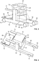
- FIGS. 2 and 3 show exemplary embodiments of the transport device 50 and the table column 20.
- the transport device 50 and the table column 20 in the FIGS. 2 and 3 shown in a correct transfer arrangement to each other, in which a transfer of the (in the FIGS. 2 and 3 not shown) patient support surface 100 is possible.
- the transport device 50 is formed from a mobile frame comprising two parallel longitudinal beams 64, 66, a cross member 68 interconnecting the two longitudinal beams 64 and 66 at one end of the transport device 50, and two handle portions 71 and 73, which are arranged above the two longitudinal beams 64, 66 parallel to these.
- the transport device 50 has four rollers, which are distributed in pairs on the longitudinal bars 64 and 66. Of the four roles are in the FIGS. 2 and 3 only three rolls labeled 70, 72 and 74 can be seen.
- the table column 20 is formed from two telescopically displaceable column parts 30 and 32.
- the table column 20 can be apart in a vertical direction and move together by the two column parts 30 and 32 are moved against each other.
- the first infrared transmitting-receiving unit 58 which includes the infrared transmitter 56 and the infrared mating receiver 60, is located on top of the one longitudinal spar 66.
- the second infrared transmitting-receiving unit 28, which includes the infrared receiver 24 and the Infrared mating transmitter 26 is disposed on the upper pillar portion 32 of the table pillar 20 on a side surface 34 which faces in the predefined transfer arrangement of the first infrared transmitting-receiving unit 58.
- the radiation characteristic is shown, with the first infrared transmitting-receiving unit 58 (more precisely, their in FIG. 2 not explicitly shown infrared transmitter 56) emits the infrared signals to the table column 20.
- the radiation characteristic is characterized by a solid angle, which is essentially limited to a travel range within which the second infrared transmitting-receiving unit 28 moves in the vertical direction when the two column parts 30 and 32 are moved against each other for adjusting the table column 20 ,
- the upper limit of movement of the second infrared transmitting-receiving unit 28 is shown by solid lines and the lower limit of movement is shown by dashed lines.
- a further infrared transmitting-receiving unit is disposed on a side facing away from the side surface 34 side surface of the upper column part 32, which is identical to the second infrared transmitting-receiving unit 28.
- the transport device 50 and the table column 20 there are two transfer arrangements of the transport device 50 and the table column 20 to each other, in which the bearing surface transfer can be performed. If only a correct transfer arrangement is to be possible, then this further infrared transmitting / receiving unit can be omitted.
- the two footswitches 52 and 54 are located on the top of the cross member 68 in the region of the longitudinal bars 64 and 66. They are thus easy for the user to reach with his feet to the first infrared transmitting-receiving unit 58th to press.
- FIG. 4 shows how the arranged on the transport device 50 patient support surface 100 is pushed up to the table column 50.
- the transport device 50 is positioned so that it is located relative to the table column 20 in the predefined transfer arrangement, which makes it possible to transfer the patient support surface 100 to the table column 20.
- the first infrared transmitting / receiving unit 58 arranged on the transport device 50 and the second infrared transmitting / receiving unit 28 arranged on the table column 20 are then paired with one another by the first infrared transmitting / receiving unit 58 first the request command A sends out and then the second infrared transmitting-receiving unit 28 with the cyclic transmission of the table column 20 individually preset device address G responds.
- This cyclical transmission of the device address G is in turn registered by the first infrared transmitting-receiving unit 58 and thus determined that the desired paired operating state is present.
- the two infrared transmit-receive units 58 and 28 are paired with each other, so by pressing one of the two foot switches 52 and 54 of the transfer command T from the first infrared transmitting-receiving unit 58 to the second infrared transceiver Unit 28 transmits, as in FIG. 7 is illustrated. Accordingly, as long as the foot switch 52 or 54 is pressed, the transfer mechanism 22 contained in the table column 20 is driven so that the table column 20 is moved vertically upward, as in FIG. 8 is shown.
- the patient support surface 100 is lifted off the transport device 50 and taken over by the table column 20.
- the patient support surface 100 is then locked in a conventional manner to the table column 20.
- the postoperative bearing surface transfer which is not explicitly shown in the figures, is accordingly carried out in the reverse order. Again, first the transport device 50 is brought into the correct transfer arrangement relative to the table column 20. Subsequently, the two infrared transmitting-receiving units 28 and 58 are paired with each other. By pressing the foot switch 52, 54, the transfer mechanism 22 contained in the table column 20 is then actuated to transfer the patient support surface 100 to the transport device 50. Finally, the remote on the transport device 50 patient support surface 100 is transported away from the table column 20.
Landscapes
- Health & Medical Sciences (AREA)
- Veterinary Medicine (AREA)
- Life Sciences & Earth Sciences (AREA)
- Animal Behavior & Ethology (AREA)
- General Health & Medical Sciences (AREA)
- Public Health (AREA)
- Engineering & Computer Science (AREA)
- Biomedical Technology (AREA)
- Physics & Mathematics (AREA)
- Nursing (AREA)
- General Physics & Mathematics (AREA)
- Electromagnetism (AREA)
- Computer Networks & Wireless Communication (AREA)
- Signal Processing (AREA)
- Accommodation For Nursing Or Treatment Tables (AREA)
- Chemical & Material Sciences (AREA)
- Combustion & Propulsion (AREA)
- Transportation (AREA)
- Mechanical Engineering (AREA)
Description
- Die Erfindung betrifft ein Operationstischsystem mit einer Transportvorrichtung zum Transportieren einer Patientenlagerfläche, einer mit der Patientenlagerfläche mechanisch koppelbaren Tischsäule, die einen Transfermechanismus aufweist, der in Abhängigkeit eines Transferbefehls zur Übergabe der Patientenlagerfläche zwischen der Transportvorrichtung und der Tischsäule ansteuerbar ist, und einer Bedieneinheit, die zum Erzeugen des Transferbefehls betätigbar ist.
- Herkömmliche Operationstischsysteme umfassen häufig eine Tischsäule und eine mit der Tischsäule mechanisch koppelbare, zur Patientenlagerung bestimmte Tischplatte, im Folgenden als Patientenlagerfläche bezeichnet. Hierdurch ist es möglich, die Patientenlagerfläche von der Tischsäule abzunehmen, um beispielsweise den Patienten außerhalb des Operationssaales auf die Operation vorzubereiten oder ihn nach der Operation schneller aus dem Operationssaal zu bringen. Das Zusammenbringen und Trennen von Patientenlagerfläche und Tischsäule wird im Folgenden auch als Lagerflächentransfer bezeichnet. Unterschieden wird dabei zwischen einem präoperativen Lagerflächentransfer und einem postoperativen Lagerflächentransfer.
- Bei dem präoperativen Lagerflächentransfer wird ein auf der Patientenlagerfläche liegender Patient mit Hilfe einer Transportvorrichtung in den Operationssaal gefahren. Die im Operationssaal angeordnete Tischsäule befindet sich dabei im eingefahrenen Zustand, so dass die Patientenlagerfläche mit Hilfe der Transportvorrichtung über der Tischsäule angeordnet werden kann. Befinden sich die Transportvorrichtung (und damit die Patientenlagerfläche) und die Tischsäule in einer vorbestimmten Transferanordnung zueinander, so kann die Tischsäule mit Hilfe eines in ihr enthaltenen Transfermechanismus nach oben gefahren werden. Beim Hochfahren kontaktiert die Tischsäule die Patientenlagerfläche von unten und hebt sie aus der Transportvorrichtung heraus. Anschließend kann die Transportvorrichtung entfernt werden. Die Tischsäule und die damit fest verriegelte Patientenlagerfläche können dann entsprechend den Anforderungen der durchzuführenden Operation über elektrische Antriebe geeignet positioniert werden.
- Bei dem postoperativen Lagerflächentransfer wird die Transportvorrichtung unter die Patientenlagerfläche gefahren. Befinden sich die Transportvorrichtung und die Tischsäule in der vorbestimmten Transferanordnung zueinander, so wird die Tischsäule nach unten gefahren. Beim Herunterfahren lösen sich die Tischsäule und die Patientenlagerfläche voneinander, während die Patientenlagerfläche von der Transportvorrichtung aufgenommen wird. Anschließend kann die Patientenlagerfäche mitsamt dem Patienten mit Hilfe der Transportvorrichtung aus dem Operationssaal gefahren werden.
- Der in der Tischsäule enthaltene Transfermechanismus, durch den die Tischsäule zum Lagerflächentransfer verfahren wird, lässt sich über eine Bedieneinheit steuern. Betätigt ein Benutzer die Bedieneinheit, so erzeugt diese einen der gewählten Funktion entsprechenden Transferbefehl, mit dem der in der Tischsäule enthaltenen Transfermechanismus angesteuert wird, um die Übergabe der Patientenlagerfläche zwischen der Transportvorrichtung und der Tischsäule in der gewünschten Weise durchzuführen.
- Bei der Aktivierung des prä- oder postoperativen Lagerflächentransfers muss sichergestellt sein, dass der von dem Benutzer über die Bedieneinheit gewählte Transferbefehl an die richtige Tischsäule gesendet wird. Andere Tischsäulen, die sich in der näheren Umgebung dieser richtigen Säule befinden, dürfen durch den gewählten Transferbefehl nicht angesprochen werden.
- Für die korrekte Übermittlung der Transferbefehle an die gewünschte Tischsäule existieren im Stand der Technik verschiedene Lösungen. So ist es beispielsweise möglich, die von dem Benutzer zu betätigende Bedieneinheit direkt in die Tischsäule zu integrieren, etwa in Form eines Bedienpanels, über das sich die wesentlichen Säulenfunktionen auswählen lassen. Eine Verwechselung zwischen verschiedenen Tischsäulen ist damit ausgeschlossen. Jedoch ist diese Lösung für den Benutzer sehr unkomfortabel, da die Tischsäule und damit das in der Tischsäule integrierte Bedienpanel insbesondere während des Lagerflächentransfers nur schlecht zugänglich sind.
- Eine andere bekannte Lösung besteht in der Verwendung einer kabelgebundenen Bedieneinheit. Da in diesem Fall die Bedieneinheit über ein Kabel mit der Tischsäule verbunden ist, ergibt sich zwangsläufig eine feste Zuordnung von Bedieneinheit und Tischsäule. Jedoch wird das Kabel häufig als störend empfunden. Außerdem muss die Bedieneinheit immer griffbereit sein.
- Eine weitere herkömmliche Lösung besteht darin, als Bedieneinheit ein mit einem Infrarotsender ausgestattetes Handgerät zu verwenden, das mit einem an der Tischsäule angeordneten Infrarotempfänger arbeitet. Die Transferbefehle lassen sich bei dieser Lösung nur dann an die Tischsäule senden, wenn zwischen dem in dem Handgerät vorgesehenen Infrarotsender und dem an der Tischsäule angeordneten Infrarotempfänger eine Sichtverbindung besteht. Um das Ansprechen einer falschen Tischsäule zu vermeiden, wird üblicherweise eine feste Paarung zwischen dem Infrarotsender und dem Infrarotempfänger hergestellt, indem Sender und Empfänger auf ein- und dieselbe Adresse eingestellt werden. Dadurch wird eine Codierung geschaffen, die sicherstellt, dass mit dem Handgerät nur diejenige Tischsäule angesprochen wird, die die vorstehend genannte Adresse aufweist. Problematisch bei dieser Lösung ist, dass unter Umständen das falsche Handgerät verwendet wird. Um dies auszuschließen, verbleibt üblicherweise das Handgerät bei der ihr zugeordneten Tischsäule in dem Operationssaal.
- Schließlich ist aus dem Stand der Technik eine Bedieneinheit in Form eines Fußschalters bekannt, der an der Transportvorrichtung angebracht ist. Befinden sich die Transportvorrichtung und die Tischsäule in der korrekten Transferanordnung zueinander, so ist der Fußschalter über ein Gestänge mechanisch mit einem an der Tischsäule angeordneten Schalter gekoppelt. Somit wird eine Druckbeaufschlagung des Fußschalters über das Gestänge auf den Schalter an der Tischsäule übertragen. Die richtige Zuordnung zwischen Bedieneinheit und Tischsäule ist so in jedem Fall sichergestellt. Gleichzeitig ist die Bedienung des Fußschalters für den Benutzer vergleichsweise komfortabel. Jedoch ist diese Lösung insbesondere dadurch, dass die Kopplung zwischen dem Fußschalter und dem an der Tischsäule angeordneten Schalter über ein mechanisches Gestänge erfolgt, vergleichsweise aufwändig. Operationstische, Transportkarren und Transfersysteme sind auch aus
GB 2 277 870 - Die Erfindung löst diese Aufgabe dadurch, dass die Bedieneinheit mindestens ein an der Transportvorrichtung angeordnetes Bedienelement und einen an der Transportvorrichtung angeordneten, mit dem Bedienelement gekoppelten Infrarotsender aufweist, der mit Betätigen des Bedienelementes den Transferbefehl in Form eines Infrarotsignals aussendet, und dass an der Tischsäule ein Infrarotempfänger angeordnet ist, der den Transferbefehl empfängt.
- Die Erfindung sieht also vor, sowohl das Bedienelement, welches der Benutzer zum Erzeugen des Transferbefehls betätigt, als auch den Infrarotsender, der den Transferbefehl an die Tischsäule sendet, an der Transportvorrichtung vorzusehen. Dabei können das Bedienelement und der Infrarotsender an der Transportvorrichtung so angebracht werden, wie dies für ihre jeweilige Funktion am besten geeignet ist. So kann die Positionierung des Infrarotsenders im Hinblick auf die benötigte Sichtverbindung zur Tischsäule optimiert werden. Beispielsweise wird der Infrarotsensor an der Transportvorrichtung so angebracht, dass die Transferbefehle mit einer vergleichsweise geringen Leistung an die Tischsäule gesendet werden können. Demgegenüber kann die Position des Bedienelementes unabhängig von der Lage des Infrarotsensors frei gewählt werden. Insbesondere kann das Bedienelement so an einer für den Benutzer ergonomisch besonders günstigen Stelle der Transportvorrichtung platziert werden. Dies erleichtert die Handhabung der Bedieneinheit erheblich.
- Da die Erfindung die Übermittlung des Transferbefehls in Form eines Infrarotsignals vorsieht, kann schon durch die benötigte Sichtverbindung, die durch die Relativanordnung von Infrarotsender und Infrarotempfänger festgelegt ist, ein versehentliches Ansprechen falscher Tischsäulen weitgehend vermieden werden. Dieser Vorteil kann dadurch verstärkt werden, dass der an der Transportvorrichtung angeordnete Infrarotsender das Infrarotsignal mit einer derart geringen Leistung aussendet, dass das Infrarotsignal von dem an der Tischsäule angeordneten Infrarotempfänger praktisch nur dann mit einer auswertbaren Leistung empfangen wird, wenn sich die Transportvorrichtung und die Tischsäule in einer vordefinierten Transferanordnung zueinander befinden, in der die Übergabe der Patientenlagerfläche stattfindet.
- Vorzugsweise weist die Bedieneinheit mindestens einen Fußschalter oder einen Fußtaster als Bedienelement auf. Die Verwendung eines Fußschalters oder Fußtasters ist ergonomisch besonders günstig, da der Benutzer die Hände frei hat. So kann er beispielsweise während des Lagerflächentransfers den Patienten behandeln, etwa eine manuelle Beatmung des Patienten durchführen.
- In einer möglichen Ausführungsform beinhaltet das mindestens eine Bedienelement zwei monofunktionale Elemente, denen jeweils eine einzige Transferfunktion zugeordnet ist, wobei die Transferfunktion des einen Elementes reziprok zu der Transferfunktion des anderen Elementes ist. Beispielsweise hat das eine der beiden genannten Elemente die Funktion, die Tischsäule hochzufahren, während das andere Element die Funktion hat, die Tischsäule herunterzufahren.
- Alternativ beinhaltet das mindestens eine Bedienelement ein bifunktionales Element, dem zwei reziproke Transferfunktionen zugeordnet sind.
- In einer besonders bevorzugten Ausgestaltung strahlt der Infrarotsender das Infrarotsignal in einen Raumwinkel ab, der im Wesentlichen auf einen Verfahrbereich begrenzt ist, innerhalb dessen sich der an der Tischsäule angeordnete Infrarotempfänger bewegt, wenn die Tischsäule in einer vorbestimmten Transferanordnung, in der sich die Tischsäule und die Transportvorrichtung zur Übergabe der Patientenlagerfläche zueinander befinden, relativ zu der Transportvorrichtung verfahren wird. Dadurch ist zum einen sichergestellt, dass über den gesamten Verfahrbereich der Tischsäule eine Sichtverbindung zwischen dem Infrarotsender und dem Infrarotempfänger besteht. Zum anderen wird durch die Begrenzung des Raumwinkels, in dem der Infrarotsender das Infrarotsignal abstrahlt, ein unbeabsichtigtes Ansprechen einer anderen Tischsäule zuverlässig vermieden.
- Um einen gepaarten Betriebszustand zwischen dem an der Transportvorrichtung angeordneten Infrarotsender und dem an der Tischsäule angeordneten Infrarotempfänger herzustellen, weist die Tischsäule einen Infrarot-Paarungssender zum Aussenden einer Säulenadresse auf, während die Transportvorrichtung einen Infrarot-Paarungsempfänger zum Empfangen der Säulenadresse hat. Mit dem vorstehend genannten gepaarten Betriebszustand ist ein Zustand gemeint, in dem der Infrarotsender der Bedieneinheit derart auf eine einzige Tischsäule eingestellt ist, dass sich nur diese Tischsäule steuerwirksam mit der Bedieneinheit ansprechen lässt. Im Unterschied zu herkömmlichen Infrarot-Fernbedienungssystemen, bei denen entweder eine feste Paarung zwischen der Bedieneinheit und einer einzigen Tischsäule vorgegeben ist oder sich die Paarung nur manuell ändern lässt, ermöglicht diese Ausführungsform gleichsam eine automatische Paarung, indem beispielsweise die von der Tischsäule ausgesendete Säulenadresse von der Transportvorrichtung übernommen und dann in der weiteren Kommunikation mit der Tischsäule als eigene Adresse genutzt wird.
- Vorzugsweise sendet der Infrarotsender der Transportvorrichtung bei Inbetriebnahme der Bedieneinheit an den Infrarotempfänger der Tischsäule einen Anforderungsbefehl, durch den der Infrarot-Paarungssender der Tischsäule aufgefordert wird, die Säulenadresse zyklisch auszusenden, wobei der gepaarte Betriebszustand dann vorliegt, wenn der Infrarot-Paarungsempfänger der Transportvorrichtung die Säulenadresse auch zyklisch empfängt. Die vorstehend genannte Inbetriebnahme kann beispielsweise durch eine erstmalige Betätigung der Bedieneinheit realisiert sein, mit der die Tischsäule konkret angesteuert, d.h. zum Lagerflächentransfer verstellt werden soll. Mit Inbetriebnahme kann jedoch auch das Einschalten der Bedieneinheit gemeint sein, also der Beginn der Speisung mit elektrischer Energie, sofern eine solche Einschaltfunktion bei der Bedieneinheit vorgesehen ist.
- Durch den zyklischen Empfang der Säulenadresse kann kontinuierlich die bestehende Sichtverbindung zwischen Transportvorrichtung und Tischsäule geprüft werden. Sobald kein zyklischer Empfang der Säulenadresse mehr gegeben ist, wird der gepaarte Betriebszustand aufgehoben und dadurch die Steuerfunktion der Bedieneinheit in Bezug auf die betrachtete Tischsäule außer Kraft gesetzt.
- Vorzugsweise liegt der gepaarte Betriebszustand nur vor, solange der Infrarot-Paarungsempfänger ein- und dieselbe Säulenadresse zyklisch empfängt. Dadurch wird vermieden, dass versehentlich nicht nur eine, sondern mehrere Tischsäulen mit der Bedieneinheit angesprochen werden. Der Infrarotsender der Transportvorrichtung sendet den Transferbefehl vorzugsweise nur dann aus, wenn bei Betätigen des Bedienelementes der gepaarte Betriebszustand vorliegt. Ist die Bedieneinheit beispielsweise ein Fußtaster, so wird bei dieser Ausführungsform der Steuerbefehl an die Tischsäule ausgegeben, solange der Fußtaster gedrückt bleibt und zugleich der gepaarte Betriebszustand aufrechterhalten bleibt. Letzteres wird vorzugsweise durch den zyklischen Empfang der Säulenadresse verifiziert.
- Die Erfindung wird im Folgenden anhand der Figuren näher erläutert. Darin zeigen:
- Fig. 1
- ein Blockdiagramm eines erfindungsgemäßen Operationstischsystems,
- Fig. 2
- eine perspektivische Ansicht einer aus einer Transportvorrichtung und einer Tischsäule gebildeten Anordnung;
- Fig. 3
- eine weitere perspektivische Ansicht der Anordnung nach
Figur 2 ; - Fig. 4
- eine schematische Darstellung, die das Operationstischsystem zu Beginn eines präoperativen Lagerflächentransfers zeigt;
- Fig. 5
- eine schematische Darstellung, die das Operationssystem in der Transferanordnung zeigt;
- Fig. 6
- eine schematische Darstellung, die das Operationssystem bei der Herstellung eines gepaarten Betriebszustands zeigt;
- Fig. 7
- eine schematische Darstellung, die das Operationssystem bei Beginn der Übernahme der Patientenlagerfläche zeigt;
- Fig. 8
- eine schematische Darstellung, die das Operationssystem am Ende der Übernahme der Patientenlagerfläche zeigt; und
- Fig. 9
- eine schematische Darstellung, die das Operationssystem am Ende des präoperativen Lagerflächentransfers zeigt.
-
Figur 1 zeigt in einem Blockdiagramm Komponenten eines erfindungsgemäßen Operationstischsystems 10. - Das Operationstischsystem 10 umfasst eine Tischsäule 20, die mit einer Patientenlagerfäche 100 mechanisch koppelbar ist, und eine Transportvorrichtung 50, die dazu dient, die Patientenlagerfläche 100 zu der Tischsäule 20 hin und von dieser weg zu transportieren.
- An der Transportvorrichtung 50 sind zwei Fußtaster 52 und 54 angeordnet, die mit einem Infrarotsensor 56 gekoppelt sind. Der Infrarotsensor 56 ist Teil einer allgemein mit 58 bezeichneten ersten Infrarot-Sende-Empfangs-Einheit. Die erste Infrarot-Sende-Empfangs-Einheit 58 enthält neben dem Infrarotsender 56 einen Infrarot-Paarungsempfänger 60. Der Infrarotsender 56 ist beispielsweise aus einer Infrarotstrahlung abgebenden Leuchtdiode gebildet, während der Infrarot-Paarungsempfänger 60 als Fotodiode ausgeführt ist. Die erste Infrarot-Sende-Empfangs-Einheit 58 bildet zusammen mit den beiden Fußtastern 52 und 54 eine in
Figur 1 allgemein mit 62 bezeichnete Bedieneinheit. - Die Tischsäule 20 enthält einen Transfermechanismus 22, der dazu dient, die Patientenlagerfläche 100 mit der Tischsäule 20 zu koppeln bzw. von dieser zu entkoppeln. Sowohl die Tischsäule 20 als auch die Patientenlagerfläche 100 verfügen hierzu über an sich bekannte und hier nicht näher beschriebene mechanische Schnittstellen, welche die mechanische Ankopplung und Entkopplung ermöglichen.
- Die Tischsäule 20 enthält ferner einen Infrarotempfänger 24, z.B. in Form einer Fotodiode, sowie einen Infrarot-Paarungssender 26, der beispielsweise als Leuchtdiode ausgeführt ist. Der Infrarotempfänger 24 und der Infrarot-Paarungssender 26 bilden eine in
Figur 1 allgemein mit 28 bezeichnete zweite Infrarot-Sende-Empfangs-Einheit, die unter der Voraussetzung einer Sichtverbindung mit der an der Transportvorrichtung 50 angeordneten ersten Infrarot-Sende-Empfangs-Einheit 58 über Infrarotsignale kommuniziert. - Der in der Tischsäule 20 enthaltene Transfermechanismus 22 wird zur Übergabe der Patientenlagerfläche 100 in Abhängigkeit eines in
Figur 1 mit T bezeichneten Transferbefehls angesteuert. Der Transferbefehl T wird von dem Infrarotsender 56 der ersten Infrarot-Sende-Empfangs-Einheit 58 an den Infrarotempfänger 24 der zweiten Infrarot-Sende-Empfangs-Einheit 28 gesendet, wenn einer der beiden Fußtaster 52 und 54 betätigt wird und zugleich ein gepaarter Betriebszustand zwischen dem Infrarotsender 56 und dem Infrarotempfänger 24 vorliegt. Um diesen gepaarten Betriebszustand herzustellen, sendet der Infrarotsender 56 bei Inbetriebnahme der Bedieneinheit 62 einen inFigur 1 mit A bezeichneten Anforderungsbefehl A an den Infrarotempfänger 24. Besteht eine Sichtverbindung zwischen dem an der Transportvorrichtung 50 angeordneten Infrarotsender 56 und dem an der Tischsäule 20 angeordneten Infrarotempfänger 24, so empfängt der Infrarotempfänger 24 den Anforderungsbefehl A. In diesem Fall wird der in der zweiten Infrarot-Sende-Empfangs-Einheit 28 enthaltene Infrarot-Paarungssensor 26 angewiesen, auf den Anforderungsbefehl A mit der zyklischen Aussendung einer inFigur 1 mit G bezeichneten Geräteadresse zu antworten. Diese wird von dem in der ersten Infrarot-Sende-Empfangs-Einheit 58 enthaltenen Infrarot-Paarungsempfänger 60 empfangen. - Solange der Infrarot-Paarungsempfänger 60 auf den Anforderungsbefehl A hin ein- und dieselbe Geräteadresse G zyklisch empfängt, sind der an der Transportvorrichtung 50 angeordnete Infrarotsender 56 und der an der Tischsäule 20 angeordnete Infrarotempfänger 24 miteinander gepaart. Solange dieser gepaarte Betriebszustand vorliegt, wird bei betätigter Fußtaste 52 bzw. 54 der Transferbefehl T von dem Infrarotempfänger 24 empfangen und in der Tischsäule 20 zur Ansteuerung des Transfermechanismus 22 verwendet. Es versteht sich dabei von selbst, dass der von dem Infrarotsender 56 in Form eines Infrarotsignals ausgegebene Transferbefehl T in der Tischsäule 20 in geeigneter Weise in ein elektrisches Signal umgewandelt wird, um zur Ansteuerung des Transfermechanismus 22 nutzbar zu sein.
- Die
Figuren 2 und 3 zeigen beispielhafte Ausführungsformen der Transportvorrichtung 50 und der Tischsäule 20. Dabei sind die Transportvorrichtung 50 und die Tischsäule 20 in denFiguren 2 und 3 in einer korrekten Transferanordnung zueinander gezeigt, in der eine Übergabe der (in denFiguren 2 und 3 nicht gezeigten) Patientenlagerfläche 100 möglich ist. - In der gezeigten Ausführungsform ist die Transportvorrichtung 50 aus einem fahrbaren Gestell gebildet, das zwei parallele Längsholme 64, 66, einen Querträger 68, der die beiden Längsholme 64 und 66 an einem Ende der Transportvorrichtung 50 miteinander verbindet, und zwei Griffteile 71 und 73 umfasst, die oberhalb der beiden Längsholme 64, 66 parallel zu diesen angeordnet sind. Die Transportvorrichtung 50 weist vier Rollen auf, die paarweise auf die Längsholme 64 und 66 verteilt sind. Von den vier Rollen sind in den
Figuren 2 und 3 nur drei mit 70, 72 und 74 bezeichnete Rollen zu sehen. - Die Tischsäule 20 ist aus zwei teleskopartig gegeneinander verschiebbaren Säulenteilen 30 und 32 gebildet. Die Tischsäule 20 lässt sich in vertikaler Richtung auseinander- und zusammenfahren, indem die beiden Säulenteile 30 und 32 gegeneinander bewegt werden.
- Die erste Infrarot-Sende-Empfangs-Einheit 58, die den Infrarotsender 56 und den Infrarot-Paarungsempfänger 60 beinhaltet, befindet sich auf der Oberseite des einen Längsholms 66. Die zweite Infrarot-Sende-Empfangs-Einheit 28, die den Infrarotempfänger 24 und den Infrarot-Paarungssender 26 enthält, ist an dem oberen Säulenteil 32 der Tischsäule 20 an einer Seitenfläche 34 angeordnet, die in der vordefinierten Transferanordnung der ersten Infrarot-Sende-Empfangs-Einheit 58 zugewandt ist.
- In
Figur 2 ist die Abstrahlcharakteristik gezeigt, mit der die erste Infrarot-Sende-Empfangs-Einheit 58 (genauer gesagt, deren inFigur 2 nicht explizit gezeigter Infrarotsender 56) die Infrarotsignale auf die Tischsäule 20 aussendet. Die Abstrahlcharakteristik ist durch einen Raumwinkel gekennzeichnet, der im Wesentlichen auf einen Verfahrbereich begrenzt ist, innerhalb dessen sich die zweite Infrarot-Sende-Empfangs-Einheit 28 in vertikaler Richtung bewegt, wenn die beiden Säulenteile 30 und 32 zum Verstellen der Tischsäule 20 gegeneinander bewegt werden. InFigur 2 ist die obere Bewegungsgrenze der zweiten Infrarot-Sende-Empfangs-Einheit 28 mit durchgezogenen Linien und die untere Bewegungsgrenze mit gestrichelten Linien dargestellt. - Bei der in
Figur 2 dargestellten Ausführungsform ist auf einer von der Seitenfläche 34 abgewandten Seitenfläche des oberen Säulenteils 32 eine weitere Infrarot-Sende-Empfangs-Einheit angeordnet, die baugleich mit der zweiten Infrarot-Sende-Empfangs-Einheit 28 ist. Somit existieren zwei Transferanordnungen der Transportvorrichtung 50 und der Tischsäule 20 zueinander, in denen sich der Lagerflächentransfer durchführen lässt. Soll nur eine korrekte Transferanordnung möglich sein, so kann diese weitere Infrarot-Sende-Empfangs-Einheit weggelassen werden. - Wie am besten in
Figur 3 zu erkennen ist, befinden sich die beiden Fußtaster 52 und 54 auf der Oberseite des Querträgers 68 im Bereich der Längsholme 64 und 66. Sie sind damit für den Benutzer mit seinen Füßen gut zu erreichen, um die erste Infrarot-Sende-Empfangs-Einheit 58 zu betätigen. - Unter Bezugnahme auf die
Figuren 4 bis 9 wird im Folgenden ein Beispiel für einen präoperativen Lagerflächentransfer beschrieben, der mit dem erfindungsgemäßen Operationssystem 10 durchgeführt wird. -
Figur 4 zeigt, wie die auf der Transportvorrichtung 50 angeordnete Patientenlagerfläche 100 an die Tischsäule 50 herangeschoben wird. InFigur 5 ist die Transportvorrichtung 50 so positioniert, dass sie sich relativ zur Tischsäule 20 in der vordefinierten Transferanordnung befindet, die eine Übergabe der Patientenlagerfläche 100 an die Tischsäule 20 ermöglicht. - In dieser Transferanordnung werden dann die an der Transportvorrichtung 50 angeordnete erste Infrarot-Sende-Empfangs-Einheit 58 und die an der Tischsäule 20 angeordnete zweite Infrarot-Sende-Empfangs-Einheit 28 miteinander gepaart, indem die erste Infrarot-Sende-Empfangs-Einheit 58 zunächst den Anforderungsbefehl A aussendet und dann die zweite Infrarot-Sende-Empfangs-Einheit 28 mit der zyklischen Aussendung der für die Tischsäule 20 individuell voreingestellten Geräteadresse G antwortet. Diese zyklische Aussendung der Geräteadresse G wird wiederum von der ersten Infrarot-Sende-Empfangs-Einheit 58 registriert und so festgestellt, dass der gewünschte gepaarte Betriebszustand vorliegt.
- Sind die beiden Infrarot-Sende-Empfangs-Einheiten 58 und 28 miteinander gepaart, so wird mit Betätigen eines der beiden Fußtaster 52 und 54 der Transferbefehl T von der ersten Infrarot-Sende-Empfangs-Einheit 58 an die zweite Infrarot-Sende-Empfangs-Einheit 28 übermittelt, wie in
Figur 7 veranschaulicht ist. Solange der Fußtaster 52 bzw. 54 gedrückt ist, wird demnach der in der Tischsäule 20 enthaltene Transfermechanismus 22 so angesteuert, dass die Tischsäule 20 vertikal nach oben verfahren wird, wie inFigur 8 gezeigt ist. - Sobald die Oberseite der Tischsäule 20 mit der Unterseite der Patientenlagerfläche 100 in Kontakt kommt, wird die Patientenlagerfläche 100 von der Transportvorrichtung 50 abgehoben und von der Tischsäule 20 übernommen. Die Patientenlagerfläche 100 wird dann in an sich bekannter Weise an der Tischsäule 20 verriegelt.
- Schließlich wird die Transportvorrichtung 50 von der Tischsäule 20 wegbewegt, wie in
Figur 9 gezeigt ist. Damit ist der präoperative Lagerflächentransfer abgeschlossen. - Der in den Figuren nicht explizit gezeigte postoperative Lagerflächentransfer wird entsprechend in umgekehrter Reihenfolge durchgeführt. Wiederum wird zunächst die Transportvorrichtung 50 relativ zu der Tischsäule 20 in die korrekte Transferanordnung gebracht. Anschließend werden die beiden Infrarot-Sende-Empfangs-Einheiten 28 und 58 miteinander gepaart. Mit mit Betätigen des Fußtasters 52, 54 wird dann der in der Tischsäule 20 enthaltene Transfermechanismus 22 zur Übergabe der Patientenlagerfläche 100 an die Transportvorrichtung 50 angesteuert. Schließlich wird die auf der Transportvorrichtung 50 abgesetzte Patientenlagerfläche 100 von der Tischsäule 20 wegtransportiert.
-
- 20
- Tischsäule
- 22
- Transfermechanismus
- 24
- Infrarotempfänger
- 26
- Infrarot-Paarungssender
- 28
- zweite Infrarot-Sende-Empfangs-Einheit
- 30, 32
- Säulenteile
- 34
- Seitenfläche
- 50
- Transportvorrichtung
- 52, 54
- Fußtaster
- 56
- Infrarotsender
- 58
- erste Infrarot-Sende-Empfangs-Einheit
- 60
- Infrarot-Paarungsempfänger
- 64, 66
- Längsholme
- 68
- Querträger
- 71, 73
- Griffteile
- 70, 72, 74
- Rollen
- 100
- Patientenlagerfläche
- T
- Transferbefehl
- A
- Anforderungsbefehl
- G
- Geräteadresse
Claims (9)
- Operationstischsystem (10) mit
einer Transportvorrichtung (50) zum Transportieren einer Patientenlagerfläche (100);
einer mit der Patientenlagerfläche (100) mechanisch koppelbaren Tischsäule (20), die einen Transfermechanismus (22) aufweist, der in Abhängigkeit eines Transferbefehls (T) zur Übergabe der Patientenlagerfläche (100) zwischen der Transportvorrichtung (50) und der Tischsäule (20) ansteuerbar ist; und
einer Bedieneinheit (62), die zum Erzeugen des Transferbefehls (T) betätigbar ist;
wobei die Bedieneinheit (62) mindestens ein an der Transportvorrichtung (50) angeordnetes Bedienelement (52, 54) und einen an der Transportvorrichtung (50) angeordneten, mit dem Bedienelement (52, 54) gekoppelten Infrarotsender (56) aufweist, der mit Betätigen des Bedienelementes (52, 54) den Transferbefehl (T) in Form eines Infrarotsignals aussendet, und an der Tischsäule (20) ein Infrarotempfänger (24) angeordnet ist, der den Transferbefehl (T) empfängt,
dadurch gekennzeichnet, dass
zum Herstellen eines gepaarten Betriebszustands zwischen dem an der Transportvorrichtung (50) angeordneten Infrarotsender (56) und dem an der Tischsäule (20) angeordneten Infrarotempfänger (24) die Tischsäule (20) einen Infrarot-Paarungssender (26) zum Aussenden einer Säulenadresse (G) und die Transportvorrichtung (50) einen Infrarot-Paarungsempfänger (60) zum Empfangen der Säulenadresse (G) aufweist. - Operationstischsystem (10) nach Anspruch 1, dadurch gekennzeichnet, dass die Bedieneinheit (62) mindestens einen Fußschalter oder einen Fußtaster (52, 54) als Bedienelement aufweist.
- Operationstischsystem (10) nach Anspruch 1 oder 2, dadurch gekennzeichnet, dass das mindestens eine Bedienelement (52, 54) zwei monofunktionale Elemente beinhaltet, denen jeweils eine einzige Transferfunktion zugeordnet ist, wobei die Transferfunktion des einen Elementes reziprok zu der Transferfunktion des anderen Elementes ist.
- Operationstischsystem (10) nach Anspruch 1 oder 2, dadurch gekennzeichnet, dass das mindestens eine Bedienelement (52, 54) ein bifunktionales Element beinhaltet, dem zwei reziproke Transferfunktionen zugeordnet sind.
- Operationstischsystem (10) nach einem der vorhergehenden Ansprüche, dadurch gekennzeichnet, dass der Infrarotsender (56) das Infrarotsignal in einen Raumwinkel abstrahlt, der im Wesentlichen auf einen Verfahrbereich begrenzt ist, innerhalb dessen sich der an der Tischsäule (20) angeordnete Infrarotempfänger (24) bewegt, wenn die Tischsäule (20) in einer vorbestimmten Transferanordnung, in der sich die Tischsäule (20) und die Transportvorrichtung (50) zur Übergabe der Patientenlagerfläche (100) zueinander befinden, relativ zu der Transportvorrichtung (50) verfahren wird.
- Operationstischsystem (10) nach einem der vorhergehenden Ansprüche, dadurch gekennzeichnet, dass der Infrarotsender (56) und der Infrarot-Paarungsempfänger (60) der Transportvorrichtung (50) eine erste Infrarot-Sende-Empfangs-Einheit (58) bilden und dass der Infrarotempfänger (24) und der Infrarot-Paarungssender (26) der Tischsäule (20) eine zweite Infrarot-Sende-Empfangs-Einheit (28) bilden.
- Operationstischsystem (10) nach einem der vorhergehenden Ansprüche, dadurch gekennzeichnet, dass der Infrarotsender (56) der Transportvorrichtung (50) bei Inbetriebnahme der Bedieneinheit (62) an den Infrarotempfänger (24) der Tischsäule (20) einen Anforderungsbefehl (A) sendet, durch den der Infrarot-Paarungssender (26) der Tischsäule (20) aufgefordert wird, die Säulenadresse (G) zyklisch auszusenden, und dass der gepaarte Betriebszustand vorliegt, wenn der Infrarot-Paarungsempfänger (60) der Transportvorrichtung (50) die Säulenadresse (G) zyklisch empfängt.
- Operationstischsystem (10) nach Anspruch 7, dadurch gekennzeichnet, dass der der gepaarte Betriebszustand nur vorliegt, solange der Infrarot-Paarungsempfänger (60) ein und dieselbe Säulenadresse (G) zyklisch empfängt.
- Operationstischsystem (10) nach einem der vorhergehenden Ansprüche, dadurch gekennzeichnet, dass der Infrarotsender (56) der Transportvorrichtung (50) den Transferbefehl (T) nur aussendet, wenn bei Betätigen des Bedienelementes (52, 54) der gepaarte Betriebszustand vorliegt.
Priority Applications (1)
| Application Number | Priority Date | Filing Date | Title |
|---|---|---|---|
| PL14736301T PL3003240T3 (pl) | 2013-06-06 | 2014-06-05 | Układ stołu operacyjnego |
Applications Claiming Priority (2)
| Application Number | Priority Date | Filing Date | Title |
|---|---|---|---|
| DE102013105825.6A DE102013105825B4 (de) | 2013-06-06 | 2013-06-06 | Operationstischsystem |
| PCT/EP2014/061666 WO2014195396A1 (de) | 2013-06-06 | 2014-06-05 | Operationstischsystem |
Publications (2)
| Publication Number | Publication Date |
|---|---|
| EP3003240A1 EP3003240A1 (de) | 2016-04-13 |
| EP3003240B1 true EP3003240B1 (de) | 2017-08-02 |
Family
ID=51136421
Family Applications (1)
| Application Number | Title | Priority Date | Filing Date |
|---|---|---|---|
| EP14736301.4A Active EP3003240B1 (de) | 2013-06-06 | 2014-06-05 | Operationstischsystem |
Country Status (10)
| Country | Link |
|---|---|
| US (1) | US10002529B2 (de) |
| EP (1) | EP3003240B1 (de) |
| JP (1) | JP6628717B2 (de) |
| KR (1) | KR101938947B1 (de) |
| CN (1) | CN105377209B (de) |
| BR (1) | BR112015029483A2 (de) |
| DE (1) | DE102013105825B4 (de) |
| PL (1) | PL3003240T3 (de) |
| RU (1) | RU2660001C2 (de) |
| WO (1) | WO2014195396A1 (de) |
Families Citing this family (6)
| Publication number | Priority date | Publication date | Assignee | Title |
|---|---|---|---|---|
| DE102012110756A1 (de) * | 2012-11-09 | 2014-06-12 | MAQUET GmbH | Transportwagen zum Transport einer Patientenlagerfläche und/oder einer Operationstischsäule eines Operationstischs |
| DE102013105825B4 (de) * | 2013-06-06 | 2017-02-09 | MAQUET GmbH | Operationstischsystem |
| DE102015109078B4 (de) | 2015-06-09 | 2019-01-03 | MAQUET GmbH | Operationstisch |
| US20180207044A1 (en) * | 2015-07-06 | 2018-07-26 | Kona Medical, Inc. | Integrated patient platform |
| CN110151421A (zh) * | 2018-03-14 | 2019-08-23 | 赵月云 | 一种具有转移功能的护理床 |
| CN113247144B (zh) * | 2021-05-17 | 2022-04-22 | 和县隆盛精密机械有限公司 | 一种用于工业区内部物流的远程遥控智能小车 |
Family Cites Families (17)
| Publication number | Priority date | Publication date | Assignee | Title |
|---|---|---|---|---|
| JPH0530759Y2 (de) * | 1987-03-31 | 1993-08-06 | ||
| GB9310057D0 (en) | 1993-05-15 | 1993-06-30 | Smiths Industries Plc | Operating tables,trolleys and transfer systems |
| JPH07131861A (ja) * | 1993-11-05 | 1995-05-19 | Shimadzu Corp | リモコンシステム |
| DE19751320A1 (de) * | 1997-11-19 | 1999-05-20 | Blanco Med Gmbh | Steuereinheit zur Ansteuerung einer Operationstischplatte |
| DE19936475A1 (de) | 1999-08-03 | 2000-04-27 | Hans Rueckstaedter | Roboter für das erleichterte Tragen und Wenden von Menschen oder von empfindlichen Gegenständen insbesondere im Krankenhaus |
| JP3673192B2 (ja) * | 2001-07-17 | 2005-07-20 | コナミ株式会社 | 遠隔操作システムに使用する送信機 |
| DE102005053754A1 (de) * | 2005-11-10 | 2007-05-16 | Maquet Gmbh & Co Kg | Einrichtung zum Verstellen der Liegefläche eines Operationstisches |
| DE102005054221A1 (de) * | 2005-11-14 | 2007-05-16 | Maquet Gmbh & Co Kg | Patientenlagersystem |
| DE102005054230A1 (de) * | 2005-11-14 | 2007-05-24 | Maquet Gmbh & Co. Kg | Verfahren und Einrichtung zur bidirektionalen IR-Datenübertragung zwischen einem Operationstisch und einem Bediengerät |
| DE102005054223A1 (de) * | 2005-11-14 | 2007-05-16 | Maquet Gmbh & Co Kg | Einrichtung zum Verstellen eines Operationstisches |
| DE102005054224A1 (de) * | 2005-11-14 | 2007-05-16 | Maquet Gmbh & Co Kg | Patientenlagersystem |
| JP5189053B2 (ja) * | 2009-08-27 | 2013-04-24 | 京セラ株式会社 | 通信機器、通信機器の通信制御方法および通信システム |
| JP5448170B2 (ja) * | 2010-01-12 | 2014-03-19 | Necカシオモバイルコミュニケーションズ株式会社 | 端末装置及びプログラム |
| DE102012110756A1 (de) * | 2012-11-09 | 2014-06-12 | MAQUET GmbH | Transportwagen zum Transport einer Patientenlagerfläche und/oder einer Operationstischsäule eines Operationstischs |
| DE102012110755A1 (de) * | 2012-11-09 | 2014-05-15 | MAQUET GmbH | Transportwagen zum Transport einer Patientenlagerfläche und/oder einer Operationstischsäule eines Operationstischs |
| DE102013105825B4 (de) * | 2013-06-06 | 2017-02-09 | MAQUET GmbH | Operationstischsystem |
| DE102013105822B4 (de) * | 2013-06-06 | 2020-09-10 | MAQUET GmbH | Verfahren und Einrichtung zum fernbetätigten Steuern von medizinischen Geräten mittels einer Fernbedienungsvorrichtung |
-
2013
- 2013-06-06 DE DE102013105825.6A patent/DE102013105825B4/de active Active
-
2014
- 2014-06-05 BR BR112015029483A patent/BR112015029483A2/pt not_active Application Discontinuation
- 2014-06-05 CN CN201480039879.9A patent/CN105377209B/zh active Active
- 2014-06-05 PL PL14736301T patent/PL3003240T3/pl unknown
- 2014-06-05 KR KR1020167000293A patent/KR101938947B1/ko not_active Expired - Fee Related
- 2014-06-05 JP JP2016517596A patent/JP6628717B2/ja active Active
- 2014-06-05 EP EP14736301.4A patent/EP3003240B1/de active Active
- 2014-06-05 RU RU2015156504A patent/RU2660001C2/ru not_active IP Right Cessation
- 2014-06-05 WO PCT/EP2014/061666 patent/WO2014195396A1/de not_active Ceased
-
2015
- 2015-11-11 US US14/938,253 patent/US10002529B2/en active Active
Non-Patent Citations (1)
| Title |
|---|
| None * |
Also Published As
| Publication number | Publication date |
|---|---|
| JP6628717B2 (ja) | 2020-01-15 |
| US20160078755A1 (en) | 2016-03-17 |
| PL3003240T3 (pl) | 2018-01-31 |
| RU2660001C2 (ru) | 2018-07-04 |
| KR101938947B1 (ko) | 2019-01-15 |
| WO2014195396A1 (de) | 2014-12-11 |
| CN105377209B (zh) | 2017-09-15 |
| JP2016521600A (ja) | 2016-07-25 |
| CN105377209A (zh) | 2016-03-02 |
| KR20160017075A (ko) | 2016-02-15 |
| BR112015029483A2 (pt) | 2017-07-25 |
| US10002529B2 (en) | 2018-06-19 |
| DE102013105825A1 (de) | 2014-12-11 |
| DE102013105825B4 (de) | 2017-02-09 |
| EP3003240A1 (de) | 2016-04-13 |
| RU2015156504A (ru) | 2017-07-20 |
Similar Documents
| Publication | Publication Date | Title |
|---|---|---|
| EP3003240B1 (de) | Operationstischsystem | |
| EP1312332B1 (de) | Verfahren und Vorrichtung zur Fernbedienung eines Operationstisches | |
| EP3005587B1 (de) | Verfahren und einrichtung zum fernbetätigten steuern von medizinischen geräten mittels einer fernbedienungsvorrichtung | |
| EP3410895B1 (de) | Elektrisch verstellbares möbelstück | |
| EP1785119B1 (de) | Operationstisch | |
| EP2139803B1 (de) | Verfahren zum steuern einer lastbewegungsvorrichtung und steuerung einer lastbewegungsvorrichtung | |
| AT515267B1 (de) | Aufsatz für eine Pressvorrichtung | |
| EP3665117A1 (de) | Fernsteuerungsanordnung | |
| EP2701860B1 (de) | Werkzeughalterung für abkantpresse | |
| EP2652567A1 (de) | Steuer- und regelvorrichtung für eine biegepresse | |
| EP1946990B1 (de) | Verfahren und Weichensteuerung zum Stellen einer elektrisch ortsgestellten Weiche | |
| WO2014170322A1 (de) | Verfahren und vorrichtung zum bedienen eines mobilen operationstischs | |
| EP3695750B1 (de) | Steuerungsverfahren zum steuern eines modularen möbelsystems | |
| DE3145975A1 (de) | "hubeinrichtung" | |
| EP1480180A1 (de) | Verfahren und Vorrichtung zur Fernsteuerung eines medizinischen Gerätes | |
| DE3133610C1 (de) | Vorrichtung zum Zuführen von Spulen zu einem Schärgatter | |
| DE102015102004B4 (de) | Stanzvorrichtung zum Ausstanzen von Teigstücken | |
| EP2644369A1 (de) | Sicheres Bedienkonzept für Faltschachtelklebemaschinen | |
| AT519776B1 (de) | Biegepressenanordnung | |
| DE29905043U1 (de) | Fernbedienungs-Vorrichtung | |
| DD155678A3 (de) | Vorrichtung zur selbsttaetigen fuehrung eines schneidwerkes von landmaschinen | |
| DE202018103520U1 (de) | Hubvorrichtung zum Anheben eines Beistellwagens sowie Hubsystem mit einem Beistellwagen und mit einer Hubvorrichtung |
Legal Events
| Date | Code | Title | Description |
|---|---|---|---|
| PUAI | Public reference made under article 153(3) epc to a published international application that has entered the european phase |
Free format text: ORIGINAL CODE: 0009012 |
|
| 17P | Request for examination filed |
Effective date: 20151109 |
|
| AK | Designated contracting states |
Kind code of ref document: A1 Designated state(s): AL AT BE BG CH CY CZ DE DK EE ES FI FR GB GR HR HU IE IS IT LI LT LU LV MC MK MT NL NO PL PT RO RS SE SI SK SM TR |
|
| AX | Request for extension of the european patent |
Extension state: BA ME |
|
| DAX | Request for extension of the european patent (deleted) | ||
| GRAP | Despatch of communication of intention to grant a patent |
Free format text: ORIGINAL CODE: EPIDOSNIGR1 |
|
| INTG | Intention to grant announced |
Effective date: 20170404 |
|
| GRAS | Grant fee paid |
Free format text: ORIGINAL CODE: EPIDOSNIGR3 |
|
| GRAA | (expected) grant |
Free format text: ORIGINAL CODE: 0009210 |
|
| AK | Designated contracting states |
Kind code of ref document: B1 Designated state(s): AL AT BE BG CH CY CZ DE DK EE ES FI FR GB GR HR HU IE IS IT LI LT LU LV MC MK MT NL NO PL PT RO RS SE SI SK SM TR |
|
| RIN1 | Information on inventor provided before grant (corrected) |
Inventor name: RATHMANN, DOROTHEE Inventor name: KOTTMANN, HEIKO Inventor name: BOESKE, WINFRIED Inventor name: RUCH, JUERGEN Inventor name: SCHMOLL, SEBASTIAN Inventor name: KOBUSS, MATTHIAS Inventor name: BAMOUNI, BAPIO Inventor name: BUERSTNER, MARKUS |
|
| REG | Reference to a national code |
Ref country code: CH Ref legal event code: EP Ref country code: AT Ref legal event code: REF Ref document number: 913667 Country of ref document: AT Kind code of ref document: T Effective date: 20170815 |
|
| REG | Reference to a national code |
Ref country code: IE Ref legal event code: FG4D Free format text: LANGUAGE OF EP DOCUMENT: GERMAN |
|
| REG | Reference to a national code |
Ref country code: DE Ref legal event code: R096 Ref document number: 502014004823 Country of ref document: DE |
|
| REG | Reference to a national code |
Ref country code: CH Ref legal event code: NV Representative=s name: WAGNER + HELBIG PATENTANWAELTE CONSEILS EN PRO, CH |
|
| REG | Reference to a national code |
Ref country code: NL Ref legal event code: MP Effective date: 20170802 |
|
| REG | Reference to a national code |
Ref country code: LT Ref legal event code: MG4D |
|
| PG25 | Lapsed in a contracting state [announced via postgrant information from national office to epo] |
Ref country code: FI Free format text: LAPSE BECAUSE OF FAILURE TO SUBMIT A TRANSLATION OF THE DESCRIPTION OR TO PAY THE FEE WITHIN THE PRESCRIBED TIME-LIMIT Effective date: 20170802 Ref country code: HR Free format text: LAPSE BECAUSE OF FAILURE TO SUBMIT A TRANSLATION OF THE DESCRIPTION OR TO PAY THE FEE WITHIN THE PRESCRIBED TIME-LIMIT Effective date: 20170802 Ref country code: NL Free format text: LAPSE BECAUSE OF FAILURE TO SUBMIT A TRANSLATION OF THE DESCRIPTION OR TO PAY THE FEE WITHIN THE PRESCRIBED TIME-LIMIT Effective date: 20170802 Ref country code: LT Free format text: LAPSE BECAUSE OF FAILURE TO SUBMIT A TRANSLATION OF THE DESCRIPTION OR TO PAY THE FEE WITHIN THE PRESCRIBED TIME-LIMIT Effective date: 20170802 Ref country code: NO Free format text: LAPSE BECAUSE OF FAILURE TO SUBMIT A TRANSLATION OF THE DESCRIPTION OR TO PAY THE FEE WITHIN THE PRESCRIBED TIME-LIMIT Effective date: 20171102 Ref country code: SE Free format text: LAPSE BECAUSE OF FAILURE TO SUBMIT A TRANSLATION OF THE DESCRIPTION OR TO PAY THE FEE WITHIN THE PRESCRIBED TIME-LIMIT Effective date: 20170802 |
|
| PG25 | Lapsed in a contracting state [announced via postgrant information from national office to epo] |
Ref country code: RS Free format text: LAPSE BECAUSE OF FAILURE TO SUBMIT A TRANSLATION OF THE DESCRIPTION OR TO PAY THE FEE WITHIN THE PRESCRIBED TIME-LIMIT Effective date: 20170802 Ref country code: BG Free format text: LAPSE BECAUSE OF FAILURE TO SUBMIT A TRANSLATION OF THE DESCRIPTION OR TO PAY THE FEE WITHIN THE PRESCRIBED TIME-LIMIT Effective date: 20171102 Ref country code: ES Free format text: LAPSE BECAUSE OF FAILURE TO SUBMIT A TRANSLATION OF THE DESCRIPTION OR TO PAY THE FEE WITHIN THE PRESCRIBED TIME-LIMIT Effective date: 20170802 Ref country code: GR Free format text: LAPSE BECAUSE OF FAILURE TO SUBMIT A TRANSLATION OF THE DESCRIPTION OR TO PAY THE FEE WITHIN THE PRESCRIBED TIME-LIMIT Effective date: 20171103 Ref country code: IS Free format text: LAPSE BECAUSE OF FAILURE TO SUBMIT A TRANSLATION OF THE DESCRIPTION OR TO PAY THE FEE WITHIN THE PRESCRIBED TIME-LIMIT Effective date: 20171202 Ref country code: LV Free format text: LAPSE BECAUSE OF FAILURE TO SUBMIT A TRANSLATION OF THE DESCRIPTION OR TO PAY THE FEE WITHIN THE PRESCRIBED TIME-LIMIT Effective date: 20170802 |
|
| PG25 | Lapsed in a contracting state [announced via postgrant information from national office to epo] |
Ref country code: RO Free format text: LAPSE BECAUSE OF FAILURE TO SUBMIT A TRANSLATION OF THE DESCRIPTION OR TO PAY THE FEE WITHIN THE PRESCRIBED TIME-LIMIT Effective date: 20170802 Ref country code: DK Free format text: LAPSE BECAUSE OF FAILURE TO SUBMIT A TRANSLATION OF THE DESCRIPTION OR TO PAY THE FEE WITHIN THE PRESCRIBED TIME-LIMIT Effective date: 20170802 |
|
| REG | Reference to a national code |
Ref country code: DE Ref legal event code: R097 Ref document number: 502014004823 Country of ref document: DE |
|
| REG | Reference to a national code |
Ref country code: FR Ref legal event code: PLFP Year of fee payment: 5 |
|
| PG25 | Lapsed in a contracting state [announced via postgrant information from national office to epo] |
Ref country code: EE Free format text: LAPSE BECAUSE OF FAILURE TO SUBMIT A TRANSLATION OF THE DESCRIPTION OR TO PAY THE FEE WITHIN THE PRESCRIBED TIME-LIMIT Effective date: 20170802 Ref country code: SK Free format text: LAPSE BECAUSE OF FAILURE TO SUBMIT A TRANSLATION OF THE DESCRIPTION OR TO PAY THE FEE WITHIN THE PRESCRIBED TIME-LIMIT Effective date: 20170802 Ref country code: SM Free format text: LAPSE BECAUSE OF FAILURE TO SUBMIT A TRANSLATION OF THE DESCRIPTION OR TO PAY THE FEE WITHIN THE PRESCRIBED TIME-LIMIT Effective date: 20170802 |
|
| PLBE | No opposition filed within time limit |
Free format text: ORIGINAL CODE: 0009261 |
|
| STAA | Information on the status of an ep patent application or granted ep patent |
Free format text: STATUS: NO OPPOSITION FILED WITHIN TIME LIMIT |
|
| 26N | No opposition filed |
Effective date: 20180503 |
|
| PG25 | Lapsed in a contracting state [announced via postgrant information from national office to epo] |
Ref country code: SI Free format text: LAPSE BECAUSE OF FAILURE TO SUBMIT A TRANSLATION OF THE DESCRIPTION OR TO PAY THE FEE WITHIN THE PRESCRIBED TIME-LIMIT Effective date: 20170802 |
|
| PG25 | Lapsed in a contracting state [announced via postgrant information from national office to epo] |
Ref country code: MT Free format text: LAPSE BECAUSE OF FAILURE TO SUBMIT A TRANSLATION OF THE DESCRIPTION OR TO PAY THE FEE WITHIN THE PRESCRIBED TIME-LIMIT Effective date: 20170802 |
|
| REG | Reference to a national code |
Ref country code: BE Ref legal event code: MM Effective date: 20180630 |
|
| REG | Reference to a national code |
Ref country code: IE Ref legal event code: MM4A |
|
| PG25 | Lapsed in a contracting state [announced via postgrant information from national office to epo] |
Ref country code: MC Free format text: LAPSE BECAUSE OF FAILURE TO SUBMIT A TRANSLATION OF THE DESCRIPTION OR TO PAY THE FEE WITHIN THE PRESCRIBED TIME-LIMIT Effective date: 20170802 Ref country code: LU Free format text: LAPSE BECAUSE OF NON-PAYMENT OF DUE FEES Effective date: 20180605 |
|
| PG25 | Lapsed in a contracting state [announced via postgrant information from national office to epo] |
Ref country code: IE Free format text: LAPSE BECAUSE OF NON-PAYMENT OF DUE FEES Effective date: 20180605 |
|
| PG25 | Lapsed in a contracting state [announced via postgrant information from national office to epo] |
Ref country code: BE Free format text: LAPSE BECAUSE OF NON-PAYMENT OF DUE FEES Effective date: 20180630 |
|
| PG25 | Lapsed in a contracting state [announced via postgrant information from national office to epo] |
Ref country code: TR Free format text: LAPSE BECAUSE OF FAILURE TO SUBMIT A TRANSLATION OF THE DESCRIPTION OR TO PAY THE FEE WITHIN THE PRESCRIBED TIME-LIMIT Effective date: 20170802 |
|
| PG25 | Lapsed in a contracting state [announced via postgrant information from national office to epo] |
Ref country code: PT Free format text: LAPSE BECAUSE OF FAILURE TO SUBMIT A TRANSLATION OF THE DESCRIPTION OR TO PAY THE FEE WITHIN THE PRESCRIBED TIME-LIMIT Effective date: 20170802 |
|
| PG25 | Lapsed in a contracting state [announced via postgrant information from national office to epo] |
Ref country code: MK Free format text: LAPSE BECAUSE OF NON-PAYMENT OF DUE FEES Effective date: 20170802 Ref country code: HU Free format text: LAPSE BECAUSE OF FAILURE TO SUBMIT A TRANSLATION OF THE DESCRIPTION OR TO PAY THE FEE WITHIN THE PRESCRIBED TIME-LIMIT; INVALID AB INITIO Effective date: 20140605 Ref country code: CY Free format text: LAPSE BECAUSE OF FAILURE TO SUBMIT A TRANSLATION OF THE DESCRIPTION OR TO PAY THE FEE WITHIN THE PRESCRIBED TIME-LIMIT Effective date: 20170802 |
|
| PG25 | Lapsed in a contracting state [announced via postgrant information from national office to epo] |
Ref country code: AL Free format text: LAPSE BECAUSE OF FAILURE TO SUBMIT A TRANSLATION OF THE DESCRIPTION OR TO PAY THE FEE WITHIN THE PRESCRIBED TIME-LIMIT Effective date: 20170802 |
|
| REG | Reference to a national code |
Ref country code: AT Ref legal event code: MM01 Ref document number: 913667 Country of ref document: AT Kind code of ref document: T Effective date: 20190605 |
|
| PG25 | Lapsed in a contracting state [announced via postgrant information from national office to epo] |
Ref country code: AT Free format text: LAPSE BECAUSE OF NON-PAYMENT OF DUE FEES Effective date: 20190605 |
|
| PGFP | Annual fee paid to national office [announced via postgrant information from national office to epo] |
Ref country code: PL Payment date: 20220322 Year of fee payment: 9 |
|
| PGFP | Annual fee paid to national office [announced via postgrant information from national office to epo] |
Ref country code: CZ Payment date: 20220516 Year of fee payment: 9 |
|
| REG | Reference to a national code |
Ref country code: DE Ref legal event code: R082 Ref document number: 502014004823 Country of ref document: DE Representative=s name: HOEFER & PARTNER PATENTANWAELTE MBB, DE |
|
| P01 | Opt-out of the competence of the unified patent court (upc) registered |
Effective date: 20230526 |
|
| PG25 | Lapsed in a contracting state [announced via postgrant information from national office to epo] |
Ref country code: CZ Free format text: LAPSE BECAUSE OF NON-PAYMENT OF DUE FEES Effective date: 20230605 |
|
| PG25 | Lapsed in a contracting state [announced via postgrant information from national office to epo] |
Ref country code: PL Free format text: LAPSE BECAUSE OF NON-PAYMENT OF DUE FEES Effective date: 20230605 |
|
| PG25 | Lapsed in a contracting state [announced via postgrant information from national office to epo] |
Ref country code: PL Free format text: LAPSE BECAUSE OF NON-PAYMENT OF DUE FEES Effective date: 20230605 |
|
| PGFP | Annual fee paid to national office [announced via postgrant information from national office to epo] |
Ref country code: DE Payment date: 20250520 Year of fee payment: 12 |
|
| PGFP | Annual fee paid to national office [announced via postgrant information from national office to epo] |
Ref country code: GB Payment date: 20250520 Year of fee payment: 12 |
|
| PGFP | Annual fee paid to national office [announced via postgrant information from national office to epo] |
Ref country code: IT Payment date: 20250520 Year of fee payment: 12 |
|
| PGFP | Annual fee paid to national office [announced via postgrant information from national office to epo] |
Ref country code: FR Payment date: 20250520 Year of fee payment: 12 |
|
| PGFP | Annual fee paid to national office [announced via postgrant information from national office to epo] |
Ref country code: CH Payment date: 20250701 Year of fee payment: 12 |