EP3002205B1 - Fahrradsteuerungsvorrichtung und verfahren zur herstellung davon - Google Patents
Fahrradsteuerungsvorrichtung und verfahren zur herstellung davon Download PDFInfo
- Publication number
- EP3002205B1 EP3002205B1 EP15186830.4A EP15186830A EP3002205B1 EP 3002205 B1 EP3002205 B1 EP 3002205B1 EP 15186830 A EP15186830 A EP 15186830A EP 3002205 B1 EP3002205 B1 EP 3002205B1
- Authority
- EP
- European Patent Office
- Prior art keywords
- lever
- region
- control
- resembling
- control device
- Prior art date
- Legal status (The legal status is an assumption and is not a legal conclusion. Google has not performed a legal analysis and makes no representation as to the accuracy of the status listed.)
- Active
Links
- 238000004519 manufacturing process Methods 0.000 title claims description 5
- 238000000034 method Methods 0.000 title claims description 4
- 239000000835 fiber Substances 0.000 claims description 16
- 239000000463 material Substances 0.000 claims description 14
- 230000003014 reinforcing effect Effects 0.000 claims description 12
- 229920001169 thermoplastic Polymers 0.000 claims description 9
- 229920001187 thermosetting polymer Polymers 0.000 claims description 9
- 239000004416 thermosoftening plastic Substances 0.000 claims description 9
- 239000002131 composite material Substances 0.000 claims description 8
- 239000011159 matrix material Substances 0.000 claims description 7
- 230000008859 change Effects 0.000 claims description 4
- 238000004132 cross linking Methods 0.000 claims description 2
- 230000001419 dependent effect Effects 0.000 claims 1
- KENZYIHFBRWMOD-UHFFFAOYSA-N 1,2-dichloro-4-(2,5-dichlorophenyl)benzene Chemical compound ClC1=CC=C(Cl)C(C=2C=C(Cl)C(Cl)=CC=2)=C1 KENZYIHFBRWMOD-UHFFFAOYSA-N 0.000 description 13
- 210000003811 finger Anatomy 0.000 description 5
- 238000005304 joining Methods 0.000 description 5
- 230000033001 locomotion Effects 0.000 description 4
- 229910000831 Steel Inorganic materials 0.000 description 3
- 229910052782 aluminium Inorganic materials 0.000 description 3
- XAGFODPZIPBFFR-UHFFFAOYSA-N aluminium Chemical compound [Al] XAGFODPZIPBFFR-UHFFFAOYSA-N 0.000 description 3
- 230000007246 mechanism Effects 0.000 description 3
- 239000010959 steel Substances 0.000 description 3
- 238000003466 welding Methods 0.000 description 3
- ZOXJGFHDIHLPTG-UHFFFAOYSA-N Boron Chemical compound [B] ZOXJGFHDIHLPTG-UHFFFAOYSA-N 0.000 description 2
- OKTJSMMVPCPJKN-UHFFFAOYSA-N Carbon Chemical compound [C] OKTJSMMVPCPJKN-UHFFFAOYSA-N 0.000 description 2
- 238000004026 adhesive bonding Methods 0.000 description 2
- 239000004760 aramid Substances 0.000 description 2
- 229920003235 aromatic polyamide Polymers 0.000 description 2
- 230000005540 biological transmission Effects 0.000 description 2
- 229910052796 boron Inorganic materials 0.000 description 2
- 229910052799 carbon Inorganic materials 0.000 description 2
- 239000000919 ceramic Substances 0.000 description 2
- 238000006073 displacement reaction Methods 0.000 description 2
- 239000003365 glass fiber Substances 0.000 description 2
- 229910052751 metal Inorganic materials 0.000 description 2
- 239000002184 metal Substances 0.000 description 2
- 238000000465 moulding Methods 0.000 description 2
- 238000003825 pressing Methods 0.000 description 2
- 239000000428 dust Substances 0.000 description 1
- 210000005224 forefinger Anatomy 0.000 description 1
- 239000012528 membrane Substances 0.000 description 1
- 239000007769 metal material Substances 0.000 description 1
- 239000002985 plastic film Substances 0.000 description 1
- 229920006255 plastic film Polymers 0.000 description 1
- 150000003071 polychlorinated biphenyls Chemical class 0.000 description 1
- 230000009467 reduction Effects 0.000 description 1
- 210000003813 thumb Anatomy 0.000 description 1
Images


Classifications
-
- B—PERFORMING OPERATIONS; TRANSPORTING
- B62—LAND VEHICLES FOR TRAVELLING OTHERWISE THAN ON RAILS
- B62K—CYCLES; CYCLE FRAMES; CYCLE STEERING DEVICES; RIDER-OPERATED TERMINAL CONTROLS SPECIALLY ADAPTED FOR CYCLES; CYCLE AXLE SUSPENSIONS; CYCLE SIDE-CARS, FORECARS, OR THE LIKE
- B62K23/00—Rider-operated controls specially adapted for cycles, i.e. means for initiating control operations, e.g. levers, grips
- B62K23/02—Rider-operated controls specially adapted for cycles, i.e. means for initiating control operations, e.g. levers, grips hand actuated
-
- H—ELECTRICITY
- H01—ELECTRIC ELEMENTS
- H01H—ELECTRIC SWITCHES; RELAYS; SELECTORS; EMERGENCY PROTECTIVE DEVICES
- H01H21/00—Switches operated by an operating part in the form of a pivotable member acted upon directly by a solid body, e.g. by a hand
- H01H21/02—Details
- H01H21/18—Movable parts; Contacts mounted thereon
- H01H21/22—Operating parts, e.g. handle
-
- B—PERFORMING OPERATIONS; TRANSPORTING
- B62—LAND VEHICLES FOR TRAVELLING OTHERWISE THAN ON RAILS
- B62K—CYCLES; CYCLE FRAMES; CYCLE STEERING DEVICES; RIDER-OPERATED TERMINAL CONTROLS SPECIALLY ADAPTED FOR CYCLES; CYCLE AXLE SUSPENSIONS; CYCLE SIDE-CARS, FORECARS, OR THE LIKE
- B62K23/00—Rider-operated controls specially adapted for cycles, i.e. means for initiating control operations, e.g. levers, grips
- B62K23/02—Rider-operated controls specially adapted for cycles, i.e. means for initiating control operations, e.g. levers, grips hand actuated
- B62K23/06—Levers
-
- B—PERFORMING OPERATIONS; TRANSPORTING
- B62—LAND VEHICLES FOR TRAVELLING OTHERWISE THAN ON RAILS
- B62M—RIDER PROPULSION OF WHEELED VEHICLES OR SLEDGES; POWERED PROPULSION OF SLEDGES OR SINGLE-TRACK CYCLES; TRANSMISSIONS SPECIALLY ADAPTED FOR SUCH VEHICLES
- B62M25/00—Actuators for gearing speed-change mechanisms specially adapted for cycles
- B62M25/08—Actuators for gearing speed-change mechanisms specially adapted for cycles with electrical or fluid transmitting systems
-
- H—ELECTRICITY
- H01—ELECTRIC ELEMENTS
- H01H—ELECTRIC SWITCHES; RELAYS; SELECTORS; EMERGENCY PROTECTIVE DEVICES
- H01H11/00—Apparatus or processes specially adapted for the manufacture of electric switches
-
- H—ELECTRICITY
- H01—ELECTRIC ELEMENTS
- H01H—ELECTRIC SWITCHES; RELAYS; SELECTORS; EMERGENCY PROTECTIVE DEVICES
- H01H21/00—Switches operated by an operating part in the form of a pivotable member acted upon directly by a solid body, e.g. by a hand
- H01H21/02—Details
- H01H21/18—Movable parts; Contacts mounted thereon
- H01H21/36—Driving mechanisms
-
- H—ELECTRICITY
- H01—ELECTRIC ELEMENTS
- H01H—ELECTRIC SWITCHES; RELAYS; SELECTORS; EMERGENCY PROTECTIVE DEVICES
- H01H2231/00—Applications
- H01H2231/026—Car
Definitions
- the present invention relates, in general, to a bicycle control device as well as to a method for manufacturing it.
- the present invention relates more specifically to a bicycle control device for imparting at least one electric-electronic control to at least one equipment of the bicycle, such as an electromechanical derailleur or a cyclecomputer.
- the expression "bicycle control device for imparting at least one electrical-electronic command” should not be taken in the limiting sense to exclude that the control device can also impart one or more mechanical command to one or more mechanical equipments of the bicycle, such as a mechanical derailleur and/or a mechanical brake.
- Known bicycle control devices comprise one or more manual actuation members, of the lever type, namely rigid bodies actuated with a rotary movement about a pivot or fulcrum, or of the button type, namely actuated with a linear movement, said manual actuation members being actuatable with one finger or with plural fingers.
- the manual actuation members are supported by a body suitable for fixing at a grip portion of the handlebars.
- the manual actuation members typically act on respective electric switches, of the microswitch type, each including a deformable dome-shaped diaphragm.
- switches of the microswitch type, each including a deformable dome-shaped diaphragm.
- an actuation head fixed to the respective manual actuation member faces the deformable diaphragm in the rest condition of the manual actuation member, and acts by pushing on the deformable diaphragm in the actuation condition of the manual actuation member.
- a bicycle typically comprises a rear brake associated with the rear wheel and/or a front brake associated with the front wheel, which are controlled by suitable control devices.
- Known brake control devices typically comprise a handlebars-fixing-body and a brake lever pivoted to the body to actuate the brake by the traction of an inextensible cable, usually sheathed (Bowden cable), when it is pulled towards the handlebars.
- a motion transmission system in a bicycle comprises a chain extending between toothed wheels associated with the axle of the pedal cranks and with the hub of the rear wheel.
- the motion transmission system is therefore provided with a gearshift, a front derailleur and/or a rear derailleur is provided for.
- a control device of the front derailleur and a control device of the rear derailleur - or only one of the two in the case of simpler gearshifts - are mounted so as to be easily manoeuvred by the cyclist, usually on the handlebars, close to the handgrips thereof where the brake lever for controlling the brake of the front and rear wheel, respectively, is also located.
- Control devices that allow driving both a derailleur in the two directions and a brake are commonly called integrated controls.
- Such integrated controls comprise, in particular, a brake lever, a first gearshift lever for example arranged behind the brake lever, and a second gearshift lever for example arranged on a proximal surface of a bicycle-fixing-body of the control device, to command an electromechanical derailleur in the two directions.
- outer, inner, upper, lower, side, distal and proximal will be used to indicate geometric and structural elements of the control device and of the components comprising it that are thus oriented in the mounted and rest condition thereof and of bicycle handlebars.
- distal and proximal are used with reference to the centre of the handlebars.
- control device of the front derailleur and the brake lever of the front wheel are located close to the left handgrip, and vice-versa the control device of the rear derailleur and the brake lever of the rear wheel are located close to the right handgrip.
- Control devices are also known wherein a single lever is capable of rotating about two or three axes to perform two or three functions among the brake control lever function, the upward gearshifting control lever function and the downward gearshifting control lever function.
- Specialised racing handlebars are also known, which have two or four bars or ends facing prominently forwards, which allow the cyclist to maintain a position of the torso greatly inclined forwards, which is aerodynamically efficient.
- specific control devices are also used, both for the brakes and for the gearshift; these devices are commonly called bar-end since they are indeed housed at the ends of the handlebars, so that the cyclist can actuate them easily without having to change his/her position.
- one or two control levers can be used to impart a command to increase the gear ratio and a command to reduce the gear ratio, control electronics that suitably drive the front and/or rear derailleur to actuate each command being provided for.
- the present invention applies to all types of control devices described above and in principle to any device suitable for imparting commands to electrical and/or electronic equipment of the bicycle, such as a derailleur, a so-called cyclecomputer, etc.
- EP 1 964 763 A1 discloses a control device according to preamble of claim 1.
- the technical problem at the basis of the invention is to provide a control device that is particularly simple to make and to mount.
- the present invention relates to a control device of a bicycle on-board electronic device, comprising:
- lever-resembling control member it is meant to indicate a control member that, in an analogous manner to a mechanical lever, has a longitudinal axis, is constrained at a first position along the longitudinal axis, and transmits a resistance force at a second position along the longitudinal axis when a driving force is applied thereto at a third position along the longitudinal axis; unlike a mechanical lever, however, a lever-resembling control member according to the invention is not a rigid body - except for unintentional deformations - that is designed to rotate about the first constraint position, rather is a body that is flexible along the longitudinal axis, that is designed to obtain a relative displacement between the driven region and the constraint region.
- the displacement essentially occurs exclusively by virtue of the elastical yield.
- the constraint region is not a pivoting region, namely it does not have pivots and/or pivot seats.
- the constraint region is a region that is irremovably fixed - in use conditions - to something else.
- the constraint region constrains said at least one lever-resembling control member to a brake lever, but it can also constrain it to a bicycle-fixing-body or to the bicycle itself.
- each lever-resembling control member is associated with only one respective switch, but a lever-resembling control member could be associated with two switches, actuating one of them if its pressing region is pushed in a first direction and another one if its pressing region is pushed in a second direction or harder in the first direction.
- two of said lever-resembling control members having the respective driven region associated with a respective switch, are made on a single body.
- control member or the single body, respectively, and the at least one electric switch can be fixed, independently of each other, to a bicycle, or to a bicycle-fixing-body, in particular to bicycle handlebars.
- control member or the single body, respectively, and the at least one electric switch can be fixed, independently of each other, to a brake lever.
- the brake lever is pivoted to a bicycle-fixing-body, in particular to bicycle handlebars.
- control "sub-set" or assembly is formed that can easily be replaced as a single block. It is therefore made easier to store sub-sets differing for example in terms of size, shape, colour, material, etc.
- the sub-sets can differ in the number of control members, for example comprising only the brake lever, or the brake lever and a lever-resembling control member, or the brake lever and two or more lever-resembling control members, or only two or more lever-resembling control members etc.
- the single body is configured to insert into a rear channel of a brake lever.
- two of said lever-resembling control members having the respective driven region associated with a respective switch, are made on a single body, a common constraint region constraining said two lever-resembling control members to a brake lever.
- the single body has a channel-shaped configuration and the at least one switch is shaped to insert within the channel of the single body.
- the electric switch is of the sudden deformation membrane type.
- the driving region there is an electric switch actuation projection.
- Such a projection can comprise an actuation pin.
- the pin is fixed with respect to the driving region, because the elasticity and "click feeling" are inherent to the elastic yield of the lever-resembling control member.
- the elastically yielding oblong body has a comparatively high yield in a pushing direction on the driving region, and a comparatively low yield in two directions perpendicular to the pushing direction and to each other.
- the elastically yielding oblong body has a comparatively low thickness in a pushing direction on the driving region, and a comparatively high thickness in two directions perpendicular to the pushing direction and to each other.
- said at least one switch is mounted on a printed circuit board (PCB).
- PCB printed circuit board
- switches when there are at least two switches, they are mounted on a same PCB, more preferably on two opposite faces of the PCB.
- the PCB is/can be housed in a casing.
- the PCB communicates wireless with the on-board electronic device, and the PCB comprises a transmitter or transceiver and a battery power source.
- the PCB communicates via cable with the on-board electronic device, a connector being provided, matching a connector on the bicycle, and preferably on the bicycle-fixing-body.
- the PCB is powered via cable by a power source of the on-board device, the power cable(s) passing in the same connector.
- said at least one switch comprises two switches mounted on a same printed circuit board (PCB), the PCB being housed within a channel defined in a single body carrying said two lever-resembling control members.
- PCB printed circuit board
- said at least two lever-resembling control members are selected from the group consisting of a member control for gearshifting in a first gearshifting direction, a member control for gearshifting in a second gearshifting direction, a member for inputting a command of an on-board electronic device.
- the bicycle on-board electronic device comprises at least one electromechanical derailleur.
- each lever-resembling control member is made of composite material comprising a matrix of thermoplastic or thermosetting material and reinforcing fibre, preferably carbon fibre, glass fibre, aramid fibre, ceramic fibre, boron fibre and/or combinations thereof.
- each lever-resembling control member is made of metal, preferably steel or aluminum, and said constraint region comprises a welding region.
- Each lever-resembling control member or said single body can be fixed to the brake lever, to the bicycle-fixing-body or directly to the bicycle through screws.
- each lever-resembling control member or said single body is co-moulded with said brake lever.
- the present invention relates to a method for manufacturing a control sub-set of a control device of a bicycle on-board electronic device, in particular as previously described, comprising the steps of:
- a control device of a bicycle on-board electronic device comprising:
- Figures 1-6 show an embodiment of a bicycle control device 10 according to the invention.
- the control device 10 is a right control device, i.e. intended to be associated with the right end of bicycle handlebars, to be actuated by the cyclist with the right hand.
- a control device intended to be associated with the left end of the handlebars will substantially be its mirror image.
- the illustrated control device 10 comprises a bicycle-fixing-body 12 suitable, in the illustrated embodiment, to be frontally fixed to a curved handgrip portion of bicycle handlebars, at a surface thereof 13 indicated as rear surface 13 with spatial reference to the condition mounted on the handlebars, so as to project frontally of the handlebars, in the travel direction.
- the fixing will take place through any connection means, like for example through the strap 14 shown.
- the bicycle-fixing-body 12 is preferably shaped and sized to be gripped by the cyclist in one travel condition, and to be just above the hand of the cyclist when he/she grips the handlebars in a different travel condition.
- the bicycle-fixing-body 12 comprises, in general, an outer or distal side surface 15 (right in the case of the right control device), an inner or proximal side surface 16 (left in the case of the right control device), an upper surface 17, a lower surface 18, and a front surface 19 opposite the aforementioned rear surface 13.
- the upper surface 17 is preferably not flat, since in the bicycle-fixing-body 12 a front-upper projection 20 is defined that preferably can be gripped by the cyclist in yet another travel condition.
- the specific shape of the bicycle-fixing-body 12 can however vary even considerably from what is illustrated and described above.
- a control sub-set or assembly 30 is mounted on the bicycle-fixing-body 12 and can be disassembled as a single piece from the bicycle-fixing-body 12, without the components of the control sub-set 30, to be described hereinafter, being disassembled from each other.
- control sub-set 30 is mounted partially housed in a front-rear recess 21 of the bicycle-fixing-body 12, preferably arranged below the front-upper projection 20.
- control device 10 - and in particular the control sub-set 30 - comprises, in the illustrated embodiment, a plurality of manual actuation members, in this case a first mechanical control lever 31 as well as a first lever-resembling control member 32 and a second lever-resembling control member 33 provided for the actuation of electric switches 71 and 72, respectively (see Fig. 3 and 4 ).
- the lever 31 is for actuating a mechanical brake
- the first lever-resembling control member 32 is for actuating a derailleur in one direction, preferably towards a toothed wheel having a larger diameter (upward gearshifting)
- the second lever-resembling control member 33 is for actuating the derailleur in a second direction, preferably towards toothed wheels having a smaller diameter (downward gearshifting).
- it is therefore a so-called integrated control device.
- lever-resembling control members 32, 33 can command the increase and reduction, respectively, of a gear ratio given overall by the front derailleur and by the rear derailleur.
- the lever 31 is articulated about a pivot 29 to the bicycle-fixing-body 12.
- the articulation pivot 29 extends in aligned holes of the lever 31 and of the bicycle-fixing-body 12, respectively indicated as 34 and 22.
- a pivot 35 is articulated to the lever 31 at its holes 36 and has a seat 37 to receive a head of a brake cable (not shown).
- a brake release mechanism 38 also per se known, comprises a pin having two operative conditions, in which it projects, respectively from one side or the other of the lever 31, through holes 39 of the lever 31, and interacts with recesses 23 of different depth of the bicycle-fixing-body 12 to tension or de-tension the brake cable, respectively.
- the switches 71, 72 are shown made on a printed circuit board (PCB) 70, more specifically on opposite faces of the PCB 70, but this is namely a preferred configuration.
- PCB printed circuit board
- the PCB 70 is preferably co-moulded with a plastic film that makes it waterproof and protects it from dust.
- the PCB 70 can be housed in a casing, preferably tight.
- the PCB 70 can comprise suitable electrical and/or electronic components that cooperate with the switches 71, 72 for generating and inputting the commands of the on-board device.
- An electric cable 73 extends from the PCB 70 to transport the control signal generated by the change of state of each switch 71, 72 to the on-board device (not shown).
- the electric cable 73 is preferably provided with a connector 74 matching a connector 24 suitably connected to the on-board electronic device (not shown).
- the cable (not shown) connected to the connector 24 preferably protrudes from the bicycle-fixing-body 12 at the recess 21.
- the lever-resembling control members 32, 33 are supported by the lever 31. Therefore, the control sub-set 30 is mounted on the bicycle-fixing-body 12 by inserting the articulation pivot 29 in the holes 22, 34, displacing the release mechanism 38 into de-tensioning position, hooking the head of the brake cable in the seat 37, and displacing the release mechanism 38 into tensioning position; the two matching connectors 24, 74 are then connected to each other, and housed in the recess 21 of the bicycle-fixing-body 12 together with the excess length of the respective electric cables.
- the control sub-set 30 is disassembled from the bicycle-fixing-body 12 as a single block, namely as if it were a single piece, with the operations in reverse.
- the lever 31 preferably has a C-shaped cross section, being defined by a front wall 40 - with reference to the mounted condition - and two side walls 41a and 41b, so as to define a channel 42 that is open rearwards.
- the front wall 40 is preferably curvilinear so as to be ergonomic.
- the side walls 41a, 41b are preferably tapered towards the free or lower end of the lever 31.
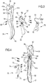
- the first lever-resembling control member 32 is preferably aligned behind the lever 31, more preferably it is partially housed within the rear channel 42 of the lever 31. In such a position, a driving region thereof 46, projecting from the channel 42, is easily accessible with the middle finger and/or forefinger, to be pushed in distal-to-proximal direction X ( Fig.5 ), namely from outside of the handlebars towards its centre, or from right to left in the case of the right control shown.
- the second lever-resembling control member 33 preferably projects cantilevered from the lever 31, also protruding from the bicycle-fixing-body 12. More preferably, the second lever-resembling control member 33 protrudes - with reference to the mounted condition - in a front-lower position from the proximal wall 16 of the bicycle-fixing-body 12. In such a position, a driving region 47 thereof, protruding from the channel 42, is easily accessible with the thumb, to be pushed in proximal-to-distal direction Y ( Fig.6 ), namely from the centre of the handlebars towards the outside, or from left to right in the case of the right control shown.
- the first and the second lever-resembling control member 32, 33 each comprise an oblong body 48, 49 respectively, which is elastically yielding in the direction X and Y, respectively, of pushing with the fingers.
- each lever-resembling control member 32, 33 has comparatively high yield in such a direction X, Y, respectively, and comparatively low yield in the directions perpendicular to the respective pushing direction X, Y.
- each lever-resembling control member 32, 33 has a comparatively low inertia in the pushing direction X, Y, and a comparatively high inertia in the directions perpendicular to the respective pushing direction X, Y.
- lever-resembling control members 32, 33 are made of composite material, this can be obtained with a suitable orientation of the reinforcing fibres, as will be understood by one skilled in the art.
- the oblong body 48 of the first lever-resembling control member 32 has a substantially flat or two-dimensional portion oriented vertically - with reference to the mounted condition - and that extends parallel and along a part of the distal side wall 41b of the lever 31, in close proximity thereto.
- the oblong body 49 of the second lever-resembling control member 33 also has a substantially flat or two-dimensional portion oriented horizontally - with reference to the mounted condition - and that extends parallel and along a short section of the proximal side wall 41a of the lever 31, in close proximity thereto.
- the two driving regions 46, 47 protrude from the lever 31, as stated above.
- the two lever-resembling control members 32, 33 are advantageously made as a single piece, the respective oblong bodies 48, 49 being joined by a flat cross-piece 50 that is housed on the back of the front wall 40 of the lever 31, namely on the bottom of the channel 42.
- the two lever-resembling control members 32, 33 with the flat joining cross-piece 50 form a single body 51 having a portion with C-shaped cross section that rests within the channel 42 of the lever 31, and that in turn forms a channel 52.
- the PCB 70 is housed within the channel 42 of the lever 31, and partially within the channel 52 of the single body 51.
- the PCB 70 is fixed to the lever 31, preferably to the proximal side wall 41a of the lever 31, in the embodiment shown through a pair of attachment screws 53 extending in a corresponding pair of holes 54 of the proximal side wall 41a of the lever 31, and screwed into a corresponding pair of holes 75 of the PCB 70.
- the PCB 70 can be constrained to the lever 31 in any other manner, for example through gluing or welding. However, the attachment through screws or rivets is preferable since it allows the PCB 70 to be easily replaced in the case of failure or breaking.
- the major faces of the PCB 70 extend parallel to the side walls 41a, 41b of the lever 31 and to the major faces of the substantially flat portions of the oblong bodies 48, 49 of the lever-resembling control members 32, 33.
- each switch 71, 72, respectively, on the PCB 70 faces a driven region 55, 56, respectively, of the first lever-resembling control member 32 and of the second lever-resembling control member 33, respectively.
- the switches 71, 72 are preferably of the microswitch type, each including a deformable dome-shaped diaphragm (not shown).
- an actuation projection of the respective lever-resembling control member 32, 33 faces the deformable diaphragm in the rest condition of the lever-resembling control member 32, 33, and acts to push on the deformable diaphragm in the actuation condition of the lever-resembling control member 32, 33.
- each driven region 55, 56 there is preferably a projection protruding from the oblong body 48, 49 of the lever-resembling control member 32, 33; said projection can be made through an actuation pin 57 fixed to the oblong body 48, 49 as shown.
- a reinforcing washer 58 is also shown around each actuation pin 57.
- the actuation projection can however also be made as a single piece with the oblong body 48, 49.
- the flat cross-piece 50 that joins the two lever-resembling control members 32, 33 in the single body 51 is constrained to the rear face of the front wall 40 of the lever 31, in the embodiment shown through a pair of attachment screws 59 extending in a corresponding pair of holes 60 of the flat cross-piece 50 and screwed into a corresponding pair of holes 61 of the front wall 40 of the lever 31.
- the holes 61 are preferably made in a widening 62 of the front wall 40 of the lever 31.
- the holes 61 can be through holes as shown, or blind holes.
- the flat cross-piece 50 can be constrained to the front wall 40 of the lever 31 in any other manner, for example through gluing or welding. However, the attachment through screws or rivets allows the lever-resembling control members 32, 33 to be easily replaced in case of breaking.
- the flat cross-piece 50 therefore forms a constraint region both for the first lever-resembling control member 32, and for the second lever-resembling control member 33.
- constraint region is not a pivoting region, rather a region that is irremovably fixed, in the case shown to the lever 31.
- the elastic yield itself of the lever-resembling actuation members 32, 33 acts validly for both purposes.
- the actuation pin 57 can indeed be replaced by a projection made as a single piece with the lever-resembling actuation members 32, 33.
- the articulation pivots of the derailleur control levers or small levers typical of the prior art are also made unnecessary.
- the cost of the control device according to the invention is therefore particularly low, it is simple and quick to mount, and its mechanical strength is particularly high.
- the lever-resembling control members 32, 33 whether they are made as a single body 51 or individually, can be made of metallic material such as steel or aluminum, but preferably they are made of a composite material like the one described above.
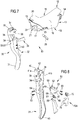
- Figures 7 and 8 show an embodiment that differs from the one shown in Figures 1-6 and described above in that the communication of commands is wireless.
- the PCB is in this case indicated with reference numeral 70A, and the cable 73 and the connectors 74, 24 are absent.
- the PCB 70A therefore comprises a transmitter - or a transceiver and a power source, for example a button battery.
- the PCB 70A can in this case comprise more sophisticated electronics than that in the PCB 70 of the embodiment with wired communication.
- Figures 9-10 show in part a control device of an embodiment that will be described only in how it differs from the one shown in Figures 1-6 and described above.
- the analogous parts are indicated with corresponding reference numerals, increased by 100.
- the first lever-resembling control member 132 and the second lever-resembling control member 133 have an identical shape to those of the previous embodiment, but they are made in a single piece not only with each other, but also with the lever 131, to provide a multi-control element 130.
- the front wall 140 of the lever 131 is made thicker at the constraint region or "cross-piece" 150 of the lever-resembling control members 132, 133. A joining region 163 is thus formed.
- Both the side walls 141a, 141b of the lever 131, and the first lever-resembling control member 132 and the second lever-resembling control member 133 extend from the front wall 140 of the lever 131, a short distance from the respective side walls 141a, 141b of the lever 131, indicated as gap 164, 165, respectively.
- Figures 9-10 omit the PCB with the switches and the actuation pins, where provided for, as well as the bicycle-fixing-body.
- This embodiment is particularly advantageous since it totally lacks connection elements for the lever-resembling control members 132, 133, and implements a multi-control element or control sub-set 130 that can be disassembled in an extremely simple manner as a single piece from the bicycle-fixing-body ( Fig. 1 ).
- This embodiment can be made of metal, for example steel or aluminum, through moulding.
- thermoplastic or thermosetting matrix with reinforcing fibre - preferably carbon fibre, glass fibre, aramid fibre, ceramic fibre, boron fibre and/or combinations thereof.
- layers of composite material are laid over one another to form the desired thickness of each part of the control sub-set 130.
- the gap 164, 165 between the lever-resembling control member 132, 133, respectively, and the adjacent side wall 141a, 141b, respectively, is formed from a thin wall of the mould or, preferably, an anti-adhesion or release material that is then removed.
- layers of reinforcing fibre are laid over one another in a half-mould until the desired shape and thickness of the region that is to form the side walls 141a, 141b of the lever 131 are formed, said layers also forming a part of the thickness of the wall in the joining region 163 and the entire thickness of the front wall 140 of the lever 131 elsewhere.
- the layers of reinforcing fibre may or may not be preimpregnated with the thermoplastic or thermosetting material.
- the length and orientation of the reinforcing fibre will be selected in a suitable manner by those skilled in the art; the reinforcing fibre may or may not be woven.
- Two sheets of suitable thickness of anti-adhesion material, or of whatever sheet material coated with an anti-adhesion film or release film, are arranged at the areas where the gaps 164, 165 are to be formed, namely the areas where the oblong bodies of the lever-resembling control members 132, 133 must extend parallel and close to the side walls 141a, 141b of the lever 131.
- the material of thermoplastic or thermosetting matrix is then inserted in the mould and the mould is closed, or injected into the already closed mould.
- the moulding chamber is subjected to a suitable temperature and/or pressure profile to cross link or set the thermoplastic or thermosetting material.
- the moulded piece is extracted from the mould and the anti-adhesion material is removed.
- control devices for curved handlebars have been shown and described, those skilled in the art will understand that the inventive concepts find an application in general in control devices for straight handlebars or T-bars, and in "bar-end" control devices for the ends of handlebar projections.
- the bicycle-fixing-body will have a substantially different shape - in a per se well known manner - to be fixed around the handlebars a certain distance from the end of the handlebars.
- the control sub-set will be fixed to the bicycle-fixing-body so as to project substantially frontally of the handgrip portion of the handlebars.
- the bicycle-fixing-body will - a per se well known way - be shaped to slip on the end of the projection.
- the control sub-set will project forwards, in the direction of travel.
- inventive concepts can also be applied in general to non-integrated control devices, namely without brake lever, to control devices of a cyclecomputer or other electronic/electromechanical device, etc.
- lever-resembling control members could be made outside of the side walls of the brake lever, or one outside and one inside, and in general they can be arranged in any suitable position on the brake lever.
- the constraint region does not necessarily have to be at the front wall of the brake lever.
- lever-resembling control members do not necessarily have to be associated with a brake lever, rather they can be directly applied to the bicycle-fixing-body of the control device - irrespective of whether it also supports a brake lever.
- lever-resembling control members described do not necessarily have to be associated with a bicycle-fixing-body, as shown, rather they can be directly applied to the bicycle, for example at the handlebars or to a tube of the frame.
- the electrical switches controlled by the lever-resembling control members can be made on the same face of a PCB, on two or more distinct PCBs, directly on the bicycle-fixing-body, or directly on the bicycle.
- lever-resembling control member More generally, there could be a single lever-resembling control member or more than two, joined together or separate.
- control device thus conceived can undergo several changes and variants, all encompassed by the invention; moreover, all of the details can be replaced by technically equivalent elements.
- the materials used, as well as the sizes, can be whatever according to the technical requirements.
Claims (11)
- Bedienungsvorrichtung (10) einer integrierten elektronischen Vorrichtung eines Fahrrades, die umfasst:- wenigstens einen elektrischen Schalter (71, 72), wobei durch eine Änderung des Status des wenigstens einen Schalters (71, 72) ein Befehl der integrierten elektronischen Vorrichtung eingegeben wird,- wenigstens ein Bedienelement (32, 33, 132, 133), das einen Haltebereich (50, 150), einen bewegenden Bereich (46, 47, 146, 147), der so eingerichtet ist, dass er mit wenigstens einem Finger gedrückt wird, sowie einen bewegten Bereich (55, 56, 155, 156) aufweist, der so eingerichtet ist, dass er den wenigstens einen Schalter (71, 72) betätigt, wenn der bewegende Bereich (46, 47, 146, 147) betätigt wird,wobei das wenigstens eine Bedienelement (32, 33, 132, 133) ein hebelartiges Bedienelement ist und der Haltebereich (50, 150), der bewegende Bereich (46, 47, 146, 147) sowie der bewegte Bereich (55, 56, 155, 156) an einem länglichen Körper (48, 49, 148, 149) ausgebildet sind, der elastisch um den Haltebereich (50, 150) herum nachgibt, dadurch gekennzeichnet, dass
der bewegte Bereich (55, 56, 155, 156) in Bezug auf den bewegenden Bereich (46, 47, 146, 147) und/oder den Haltebereich (50, 150) aufgrund der elastischen Nachgiebigkeit gezielt verschoben wird. - Bedienungsvorrichtung (10) nach Anspruch 1, wobei der Haltebereich (50, 150) kein Schwenkbereich ist.
- Bedienungsvorrichtung (10) nach Anspruch 1 oder 2, wobei der Haltebereich (50, 150) das wenigstens eine hebelartige Bedienelement (32, 33, 132, 133) an einem Bremshebel (31, 131) hält.
- Bedienungsvorrichtung (10) nach einem der vorangehenden Ansprüche, wobei zwei der hebelartigen Bedienelemente (32, 33, 132, 133), die den jeweiligen bewegten Bereich (55, 56, 155, 156) aufweisen, der mit einem entsprechenden Schalter (71, 72) verbunden ist, an einem einzelnen Körper (51, 151) ausgebildet sind.
- Bedienungsvorrichtung (10) nach Anspruch 4, wobei ein gemeinsamer Haltebereich (50, 150) die zwei hebelartigen Bedienelemente (32, 33, 132, 133) an einem Bremshebel (31, 131) hält.
- Bedienungsvorrichtung (10) nach Anspruch 5, wobei der einzelne Körper (51, 151) einen rinnenförmigen Aufbau (52, 152) hat, und der wenigstens eine Schalter (71, 72) so geformt ist, dass er in die Rinne (52, 152) des einzelnen Körpers (51, 151) eingeführt wird.
- Bedienungsvorrichtung (10) nach einem der vorangehenden Ansprüche, wobei der elastisch nachgebende längliche Körper (48, 49, 148, 149) eine vergleichsweise starke Nachgiebigkeit in einer Richtung (X, Y), in der auf den bewegenden Bereich (46, 47, 146, 147) gedrückt wird, und eine vergleichsweise schwache Nachgiebigkeit in zwei Richtungen aufweist, die senkrecht zu der Drück-Richtung (X, Y) und zueinander sind.
- Bedienungsvorrichtung (10) nach Anspruch 7, wobei der elastisch nachgiebige längliche Körper (48, 49, 148, 149) eine vergleichsweise kleine Dicke in einer Richtung (X, Y), in der auf den bewegenden Bereich (46, 47, 146, 147) gedrückt wird, und eine vergleichsweise große Dicke in zwei Richtungen hat, die senkrecht zu der Drück-Richtung (X, Y) und zueinander sind.
- Bedienungsvorrichtung (10) nach einem der Ansprüche 4 bis 6, wobei
der wenigstens eine Schalter (71, 72) zwei Schalter (71, 72) umfasst, die auf ein und derselben Leiterplatte (70, 70A) montiert sind, wobei die Leiterplatte (70, 70A) in einer Rinne (52, 152) aufgenommen ist, die in dem einzelnen Körper (51, 151) ausgebildet ist, der die beiden hebelartigen Bedienelemente (32, 33, 132, 133) trägt. - Bedienungsvorrichtung (10) nach einem der Ansprüche 4 bis 6, wenn abhängig von Anspruch 3, wobei jedes hebelartige Bedienelement (132, 133) oder der einzelne Körper (151) mit dem Bremshebel (131) zusammen geformt wird.
- Verfahren zum Herstellen einer Bedienungs-Teilgruppe (130) einer Bedienungsvorrichtung (10) einer integrierten elektronischen Vorrichtung eines Fahrrades nach Anspruch 1, das die folgenden Schritte umfasst:- Anordnen wenigstens einer Schicht aus Verbundmaterial, das eine thermoplastische oder wärmehärtende Matrix mit verstärkender Faser umfasst, in einer Form, um einen Bedienhebel (131) und das wenigstens eine hebelartige Bedienelement (132, 133) als ein Einzelteil (130) auszubilden,- Anordnen eines Antihaftmaterials in der Form zwischen dem Hebel (131) und dem wenigstens einen hebelartigen Bedienelement (132, 133),- Veranlassen, dass ein geeignetes Temperatur- und/oder Druck-Profil zum Vernetzen oder Aushärten der thermoplastischen oder wärmehärtenden Matrix auf den Formhohlraum wirkt,- Entnehmen des Einzelteils (130) aus der Form,- Entfernen des Antihaftmaterials.
Applications Claiming Priority (1)
| Application Number | Priority Date | Filing Date | Title |
|---|---|---|---|
| ITMI20141739 | 2014-10-03 |
Publications (2)
| Publication Number | Publication Date |
|---|---|
| EP3002205A1 EP3002205A1 (de) | 2016-04-06 |
| EP3002205B1 true EP3002205B1 (de) | 2019-08-21 |
Family
ID=52000940
Family Applications (1)
| Application Number | Title | Priority Date | Filing Date |
|---|---|---|---|
| EP15186830.4A Active EP3002205B1 (de) | 2014-10-03 | 2015-09-25 | Fahrradsteuerungsvorrichtung und verfahren zur herstellung davon |
Country Status (5)
| Country | Link |
|---|---|
| US (1) | US9711304B2 (de) |
| EP (1) | EP3002205B1 (de) |
| JP (1) | JP6584897B2 (de) |
| CN (1) | CN105480362B (de) |
| TW (1) | TWI687342B (de) |
Families Citing this family (4)
| Publication number | Priority date | Publication date | Assignee | Title |
|---|---|---|---|---|
| US10566147B2 (en) * | 2017-03-07 | 2020-02-18 | Karl A. Burkett | Physical barrier breach sensor |
| TWI677454B (zh) * | 2018-02-14 | 2019-11-21 | 彥豪金屬工業股份有限公司 | 剎車變速組件 |
| US11505271B2 (en) * | 2020-05-27 | 2022-11-22 | Shimano Inc. | Operating device |
| US20230067171A1 (en) * | 2021-08-26 | 2023-03-02 | Sram, Llc | Electronic shift control system for a bicycle |
Family Cites Families (23)
| Publication number | Priority date | Publication date | Assignee | Title |
|---|---|---|---|---|
| US5446628A (en) | 1994-03-17 | 1995-08-29 | Blom; Richard P. | Flexible fibre optic system for bicycle illumination |
| ITTO20010555A1 (it) * | 2001-06-08 | 2002-12-08 | Campagnolo Srl | Dispositivo di comando elettrico per un deragliatore motorizzato per biciclette. |
| JP2003252271A (ja) | 2002-02-27 | 2003-09-10 | Shimano Inc | 自転車用表示装置 |
| DE20214095U1 (de) | 2002-09-12 | 2004-02-12 | Plim Cooperation Ag | Fahrradfrontleuchte |
| US6974222B2 (en) | 2003-03-31 | 2005-12-13 | Honda Motor Company, Ltd. | Light distribution plenum for an illuminated control assembly and method |
| US7350436B2 (en) * | 2004-03-29 | 2008-04-01 | Shimano, Inc. | Electrical bicycle shift control device |
| DE502005008051D1 (de) | 2005-07-12 | 2009-10-15 | Shimano Kk | Beleuchtungsvorrichtung für ein Fahrrad mit zusätzlichem elektrischen Ausgang |
| US7703350B2 (en) * | 2006-02-01 | 2010-04-27 | Shimano Inc. | Bicycle control device |
| US7363873B2 (en) | 2006-02-21 | 2008-04-29 | Shimano Inc. | Bicycle shift control device with light structure |
| US7582838B2 (en) | 2006-04-06 | 2009-09-01 | Streamlight, Inc. | Flashlight electrical switch and charging indicator |
| JP2008168751A (ja) * | 2007-01-11 | 2008-07-24 | Shimano Inc | 自転車用ブレーキ及び変速操作装置 |
| ITMI20070398A1 (it) * | 2007-03-01 | 2008-09-02 | Campagnolo Srl | Dispositivo di comando per bicicletta e bicicletta che lo comprende |
| ITMI20070399A1 (it) * | 2007-03-01 | 2008-09-02 | Campagnolo Srl | Dispositivo di comando per bicicletta e bicicletta che lo comprende |
| US7665384B2 (en) * | 2007-06-01 | 2010-02-23 | Shimano Inc. | Bicycle control device |
| JP2009029345A (ja) * | 2007-07-30 | 2009-02-12 | Shimano Inc | 自転車用ブレーキ及び変速操作装置 |
| DE102009005777B4 (de) | 2009-01-22 | 2011-05-12 | Blohm, Claudia | Beleuchtung für Fahrzeuge |
| US9132886B2 (en) * | 2009-10-07 | 2015-09-15 | Shimano Inc. | Shift operating device |
| JP3166295U (ja) | 2010-12-16 | 2011-02-24 | 臺灣▲イ▼冠軸承有限公司 | 警告機能付きブレーキレバー |
| US10479438B2 (en) * | 2011-03-31 | 2019-11-19 | Shimano Inc. | Bicycle brake and shift operating device |
| JP2013006466A (ja) | 2011-06-23 | 2013-01-10 | Asahi Denso Co Ltd | ハンドルバー用スイッチ装置 |
| TWM427342U (en) | 2011-09-28 | 2012-04-21 | Chuan-Zhuo Wang | Draw lever with light emitting elements |
| US8746105B2 (en) * | 2012-02-24 | 2014-06-10 | Shimano Inc. | Bicycle operating device |
| CN202806571U (zh) | 2012-06-14 | 2013-03-20 | 广东华钿勇士汽车用品有限公司 | 可辅助照明的汽车防滑踏板 |
-
2015
- 2015-09-25 TW TW104131884A patent/TWI687342B/zh active
- 2015-09-25 EP EP15186830.4A patent/EP3002205B1/de active Active
- 2015-10-02 JP JP2015196426A patent/JP6584897B2/ja active Active
- 2015-10-02 US US14/873,954 patent/US9711304B2/en active Active
- 2015-10-08 CN CN201510645216.8A patent/CN105480362B/zh active Active
Non-Patent Citations (1)
| Title |
|---|
| None * |
Also Published As
| Publication number | Publication date |
|---|---|
| CN105480362A (zh) | 2016-04-13 |
| TW201613799A (en) | 2016-04-16 |
| JP2016074417A (ja) | 2016-05-12 |
| EP3002205A1 (de) | 2016-04-06 |
| JP6584897B2 (ja) | 2019-10-02 |
| TWI687342B (zh) | 2020-03-11 |
| US20160099121A1 (en) | 2016-04-07 |
| CN105480362B (zh) | 2019-12-17 |
| US9711304B2 (en) | 2017-07-18 |
Similar Documents
| Publication | Publication Date | Title |
|---|---|---|
| EP3002205B1 (de) | Fahrradsteuerungsvorrichtung und verfahren zur herstellung davon | |
| US10450024B2 (en) | Bicycle control lever and method for manufacturing it | |
| US9862442B2 (en) | Bicycle control device | |
| US9090304B2 (en) | Bicycle control device | |
| EP1955942B1 (de) | Fahrradbremse und Betätigungsvorrichtung für eine Fahrradgangschaltung | |
| EP1264765B1 (de) | Elektrisch gesteuerte Getriebe für die Steuerung eines Kettenräderwechselgetriebes eines Fahrrads | |
| EP1473220A1 (de) | Steuereinrichtung für Fahrradkettenumwerfer | |
| EP2554466B1 (de) | Steuervorrichtung für eine Fahrradkomponente | |
| US20080210045A1 (en) | Control device for a bicycle and bicycle comprising same | |
| EP3590816B1 (de) | Steuerungsvorrichtung eines fahrrads befestigt am lenker | |
| EP4124554A1 (de) | Manuelle steuerungsvorrichtung für ein fahrrad | |
| US20230032763A1 (en) | Manual control device for a bicycle | |
| IT202100019988A1 (it) | Dispositivo manuale di comando per bicicletta | |
| TW202306838A (zh) | 用於自行車的手動控制裝置 | |
| EP1964765A1 (de) | Steuervorrichtung für ein Fahrrad und Fahrrad mit einer solchen Vorrichtung | |
| TW202304767A (zh) | 用於自行車的手動控制裝置 | |
| EP3159251A1 (de) | Bedienungshebel für fahrrad und herstellungsverfahren dafür | |
| ITUB201561429U1 (it) | Dispositivo manuale di comando per bicicletta, in particolare di freno idraulico e cambio elettrico-elettronico. | |
| US20130145884A1 (en) | Unknown |
Legal Events
| Date | Code | Title | Description |
|---|---|---|---|
| PUAI | Public reference made under article 153(3) epc to a published international application that has entered the european phase |
Free format text: ORIGINAL CODE: 0009012 |
|
| AK | Designated contracting states |
Kind code of ref document: A1 Designated state(s): AL AT BE BG CH CY CZ DE DK EE ES FI FR GB GR HR HU IE IS IT LI LT LU LV MC MK MT NL NO PL PT RO RS SE SI SK SM TR |
|
| AX | Request for extension of the european patent |
Extension state: BA ME |
|
| 17P | Request for examination filed |
Effective date: 20161004 |
|
| RBV | Designated contracting states (corrected) |
Designated state(s): AL AT BE BG CH CY CZ DE DK EE ES FI FR GB GR HR HU IE IS IT LI LT LU LV MC MK MT NL NO PL PT RO RS SE SI SK SM TR |
|
| STAA | Information on the status of an ep patent application or granted ep patent |
Free format text: STATUS: EXAMINATION IS IN PROGRESS |
|
| 17Q | First examination report despatched |
Effective date: 20170726 |
|
| REG | Reference to a national code |
Ref country code: DE Ref legal event code: R079 Ref document number: 602015036165 Country of ref document: DE Free format text: PREVIOUS MAIN CLASS: B62K0023060000 Ipc: H01H0011000000 |
|
| GRAP | Despatch of communication of intention to grant a patent |
Free format text: ORIGINAL CODE: EPIDOSNIGR1 |
|
| STAA | Information on the status of an ep patent application or granted ep patent |
Free format text: STATUS: GRANT OF PATENT IS INTENDED |
|
| RIC1 | Information provided on ipc code assigned before grant |
Ipc: B62K 23/06 20060101ALI20190125BHEP Ipc: H01H 21/22 20060101ALI20190125BHEP Ipc: H01H 11/00 20060101AFI20190125BHEP Ipc: H01H 21/36 20060101ALI20190125BHEP Ipc: B62M 25/08 20060101ALI20190125BHEP |
|
| INTG | Intention to grant announced |
Effective date: 20190213 |
|
| GRAS | Grant fee paid |
Free format text: ORIGINAL CODE: EPIDOSNIGR3 |
|
| GRAA | (expected) grant |
Free format text: ORIGINAL CODE: 0009210 |
|
| STAA | Information on the status of an ep patent application or granted ep patent |
Free format text: STATUS: THE PATENT HAS BEEN GRANTED |
|
| AK | Designated contracting states |
Kind code of ref document: B1 Designated state(s): AL AT BE BG CH CY CZ DE DK EE ES FI FR GB GR HR HU IE IS IT LI LT LU LV MC MK MT NL NO PL PT RO RS SE SI SK SM TR |
|
| REG | Reference to a national code |
Ref country code: GB Ref legal event code: FG4D |
|
| REG | Reference to a national code |
Ref country code: CH Ref legal event code: EP |
|
| REG | Reference to a national code |
Ref country code: DE Ref legal event code: R096 Ref document number: 602015036165 Country of ref document: DE |
|
| REG | Reference to a national code |
Ref country code: AT Ref legal event code: REF Ref document number: 1170701 Country of ref document: AT Kind code of ref document: T Effective date: 20190915 |
|
| REG | Reference to a national code |
Ref country code: IE Ref legal event code: FG4D |
|
| REG | Reference to a national code |
Ref country code: LT Ref legal event code: MG4D |
|
| REG | Reference to a national code |
Ref country code: NL Ref legal event code: MP Effective date: 20190821 |
|
| PG25 | Lapsed in a contracting state [announced via postgrant information from national office to epo] |
Ref country code: FI Free format text: LAPSE BECAUSE OF FAILURE TO SUBMIT A TRANSLATION OF THE DESCRIPTION OR TO PAY THE FEE WITHIN THE PRESCRIBED TIME-LIMIT Effective date: 20190821 Ref country code: PT Free format text: LAPSE BECAUSE OF FAILURE TO SUBMIT A TRANSLATION OF THE DESCRIPTION OR TO PAY THE FEE WITHIN THE PRESCRIBED TIME-LIMIT Effective date: 20191223 Ref country code: NL Free format text: LAPSE BECAUSE OF FAILURE TO SUBMIT A TRANSLATION OF THE DESCRIPTION OR TO PAY THE FEE WITHIN THE PRESCRIBED TIME-LIMIT Effective date: 20190821 Ref country code: SE Free format text: LAPSE BECAUSE OF FAILURE TO SUBMIT A TRANSLATION OF THE DESCRIPTION OR TO PAY THE FEE WITHIN THE PRESCRIBED TIME-LIMIT Effective date: 20190821 Ref country code: HR Free format text: LAPSE BECAUSE OF FAILURE TO SUBMIT A TRANSLATION OF THE DESCRIPTION OR TO PAY THE FEE WITHIN THE PRESCRIBED TIME-LIMIT Effective date: 20190821 Ref country code: BG Free format text: LAPSE BECAUSE OF FAILURE TO SUBMIT A TRANSLATION OF THE DESCRIPTION OR TO PAY THE FEE WITHIN THE PRESCRIBED TIME-LIMIT Effective date: 20191121 Ref country code: LT Free format text: LAPSE BECAUSE OF FAILURE TO SUBMIT A TRANSLATION OF THE DESCRIPTION OR TO PAY THE FEE WITHIN THE PRESCRIBED TIME-LIMIT Effective date: 20190821 Ref country code: NO Free format text: LAPSE BECAUSE OF FAILURE TO SUBMIT A TRANSLATION OF THE DESCRIPTION OR TO PAY THE FEE WITHIN THE PRESCRIBED TIME-LIMIT Effective date: 20191121 |
|
| PG25 | Lapsed in a contracting state [announced via postgrant information from national office to epo] |
Ref country code: ES Free format text: LAPSE BECAUSE OF FAILURE TO SUBMIT A TRANSLATION OF THE DESCRIPTION OR TO PAY THE FEE WITHIN THE PRESCRIBED TIME-LIMIT Effective date: 20190821 Ref country code: LV Free format text: LAPSE BECAUSE OF FAILURE TO SUBMIT A TRANSLATION OF THE DESCRIPTION OR TO PAY THE FEE WITHIN THE PRESCRIBED TIME-LIMIT Effective date: 20190821 Ref country code: AL Free format text: LAPSE BECAUSE OF FAILURE TO SUBMIT A TRANSLATION OF THE DESCRIPTION OR TO PAY THE FEE WITHIN THE PRESCRIBED TIME-LIMIT Effective date: 20190821 Ref country code: GR Free format text: LAPSE BECAUSE OF FAILURE TO SUBMIT A TRANSLATION OF THE DESCRIPTION OR TO PAY THE FEE WITHIN THE PRESCRIBED TIME-LIMIT Effective date: 20191122 Ref country code: IS Free format text: LAPSE BECAUSE OF FAILURE TO SUBMIT A TRANSLATION OF THE DESCRIPTION OR TO PAY THE FEE WITHIN THE PRESCRIBED TIME-LIMIT Effective date: 20191221 Ref country code: RS Free format text: LAPSE BECAUSE OF FAILURE TO SUBMIT A TRANSLATION OF THE DESCRIPTION OR TO PAY THE FEE WITHIN THE PRESCRIBED TIME-LIMIT Effective date: 20190821 |
|
| REG | Reference to a national code |
Ref country code: AT Ref legal event code: MK05 Ref document number: 1170701 Country of ref document: AT Kind code of ref document: T Effective date: 20190821 |
|
| PG25 | Lapsed in a contracting state [announced via postgrant information from national office to epo] |
Ref country code: TR Free format text: LAPSE BECAUSE OF FAILURE TO SUBMIT A TRANSLATION OF THE DESCRIPTION OR TO PAY THE FEE WITHIN THE PRESCRIBED TIME-LIMIT Effective date: 20190821 |
|
| PG25 | Lapsed in a contracting state [announced via postgrant information from national office to epo] |
Ref country code: EE Free format text: LAPSE BECAUSE OF FAILURE TO SUBMIT A TRANSLATION OF THE DESCRIPTION OR TO PAY THE FEE WITHIN THE PRESCRIBED TIME-LIMIT Effective date: 20190821 Ref country code: PL Free format text: LAPSE BECAUSE OF FAILURE TO SUBMIT A TRANSLATION OF THE DESCRIPTION OR TO PAY THE FEE WITHIN THE PRESCRIBED TIME-LIMIT Effective date: 20190821 Ref country code: RO Free format text: LAPSE BECAUSE OF FAILURE TO SUBMIT A TRANSLATION OF THE DESCRIPTION OR TO PAY THE FEE WITHIN THE PRESCRIBED TIME-LIMIT Effective date: 20190821 Ref country code: AT Free format text: LAPSE BECAUSE OF FAILURE TO SUBMIT A TRANSLATION OF THE DESCRIPTION OR TO PAY THE FEE WITHIN THE PRESCRIBED TIME-LIMIT Effective date: 20190821 Ref country code: DK Free format text: LAPSE BECAUSE OF FAILURE TO SUBMIT A TRANSLATION OF THE DESCRIPTION OR TO PAY THE FEE WITHIN THE PRESCRIBED TIME-LIMIT Effective date: 20190821 |
|
| PG25 | Lapsed in a contracting state [announced via postgrant information from national office to epo] |
Ref country code: CZ Free format text: LAPSE BECAUSE OF FAILURE TO SUBMIT A TRANSLATION OF THE DESCRIPTION OR TO PAY THE FEE WITHIN THE PRESCRIBED TIME-LIMIT Effective date: 20190821 Ref country code: SK Free format text: LAPSE BECAUSE OF FAILURE TO SUBMIT A TRANSLATION OF THE DESCRIPTION OR TO PAY THE FEE WITHIN THE PRESCRIBED TIME-LIMIT Effective date: 20190821 Ref country code: SM Free format text: LAPSE BECAUSE OF FAILURE TO SUBMIT A TRANSLATION OF THE DESCRIPTION OR TO PAY THE FEE WITHIN THE PRESCRIBED TIME-LIMIT Effective date: 20190821 Ref country code: MC Free format text: LAPSE BECAUSE OF FAILURE TO SUBMIT A TRANSLATION OF THE DESCRIPTION OR TO PAY THE FEE WITHIN THE PRESCRIBED TIME-LIMIT Effective date: 20190821 Ref country code: IS Free format text: LAPSE BECAUSE OF FAILURE TO SUBMIT A TRANSLATION OF THE DESCRIPTION OR TO PAY THE FEE WITHIN THE PRESCRIBED TIME-LIMIT Effective date: 20200224 |
|
| REG | Reference to a national code |
Ref country code: CH Ref legal event code: PL |
|
| REG | Reference to a national code |
Ref country code: DE Ref legal event code: R097 Ref document number: 602015036165 Country of ref document: DE |
|
| PLBE | No opposition filed within time limit |
Free format text: ORIGINAL CODE: 0009261 |
|
| STAA | Information on the status of an ep patent application or granted ep patent |
Free format text: STATUS: NO OPPOSITION FILED WITHIN TIME LIMIT |
|
| PG2D | Information on lapse in contracting state deleted |
Ref country code: IS |
|
| PG25 | Lapsed in a contracting state [announced via postgrant information from national office to epo] |
Ref country code: LU Free format text: LAPSE BECAUSE OF NON-PAYMENT OF DUE FEES Effective date: 20190925 Ref country code: IE Free format text: LAPSE BECAUSE OF NON-PAYMENT OF DUE FEES Effective date: 20190925 Ref country code: LI Free format text: LAPSE BECAUSE OF NON-PAYMENT OF DUE FEES Effective date: 20190930 Ref country code: CH Free format text: LAPSE BECAUSE OF NON-PAYMENT OF DUE FEES Effective date: 20190930 |
|
| 26N | No opposition filed |
Effective date: 20200603 |
|
| REG | Reference to a national code |
Ref country code: BE Ref legal event code: MM Effective date: 20190930 |
|
| PG25 | Lapsed in a contracting state [announced via postgrant information from national office to epo] |
Ref country code: SI Free format text: LAPSE BECAUSE OF FAILURE TO SUBMIT A TRANSLATION OF THE DESCRIPTION OR TO PAY THE FEE WITHIN THE PRESCRIBED TIME-LIMIT Effective date: 20190821 Ref country code: BE Free format text: LAPSE BECAUSE OF NON-PAYMENT OF DUE FEES Effective date: 20190930 |
|
| GBPC | Gb: european patent ceased through non-payment of renewal fee |
Effective date: 20191121 |
|
| PG25 | Lapsed in a contracting state [announced via postgrant information from national office to epo] |
Ref country code: GB Free format text: LAPSE BECAUSE OF NON-PAYMENT OF DUE FEES Effective date: 20191121 |
|
| PG25 | Lapsed in a contracting state [announced via postgrant information from national office to epo] |
Ref country code: CY Free format text: LAPSE BECAUSE OF FAILURE TO SUBMIT A TRANSLATION OF THE DESCRIPTION OR TO PAY THE FEE WITHIN THE PRESCRIBED TIME-LIMIT Effective date: 20190821 |
|
| PG25 | Lapsed in a contracting state [announced via postgrant information from national office to epo] |
Ref country code: HU Free format text: LAPSE BECAUSE OF FAILURE TO SUBMIT A TRANSLATION OF THE DESCRIPTION OR TO PAY THE FEE WITHIN THE PRESCRIBED TIME-LIMIT; INVALID AB INITIO Effective date: 20150925 Ref country code: MT Free format text: LAPSE BECAUSE OF FAILURE TO SUBMIT A TRANSLATION OF THE DESCRIPTION OR TO PAY THE FEE WITHIN THE PRESCRIBED TIME-LIMIT Effective date: 20190821 |
|
| PG25 | Lapsed in a contracting state [announced via postgrant information from national office to epo] |
Ref country code: MK Free format text: LAPSE BECAUSE OF FAILURE TO SUBMIT A TRANSLATION OF THE DESCRIPTION OR TO PAY THE FEE WITHIN THE PRESCRIBED TIME-LIMIT Effective date: 20190821 |
|
| P01 | Opt-out of the competence of the unified patent court (upc) registered |
Effective date: 20230518 |
|
| PGFP | Annual fee paid to national office [announced via postgrant information from national office to epo] |
Ref country code: IT Payment date: 20230921 Year of fee payment: 9 |
|
| PGFP | Annual fee paid to national office [announced via postgrant information from national office to epo] |
Ref country code: FR Payment date: 20230925 Year of fee payment: 9 Ref country code: DE Payment date: 20230927 Year of fee payment: 9 |