EP3001135A1 - Lance missile - Google Patents
Lance missile Download PDFInfo
- Publication number
- EP3001135A1 EP3001135A1 EP15186723.1A EP15186723A EP3001135A1 EP 3001135 A1 EP3001135 A1 EP 3001135A1 EP 15186723 A EP15186723 A EP 15186723A EP 3001135 A1 EP3001135 A1 EP 3001135A1
- Authority
- EP
- European Patent Office
- Prior art keywords
- tube
- missile
- lever
- flap
- lance
- Prior art date
- Legal status (The legal status is an assumption and is not a legal conclusion. Google has not performed a legal analysis and makes no representation as to the accuracy of the status listed.)
- Granted
Links
Images


Classifications
-
- F—MECHANICAL ENGINEERING; LIGHTING; HEATING; WEAPONS; BLASTING
- F41—WEAPONS
- F41F—APPARATUS FOR LAUNCHING PROJECTILES OR MISSILES FROM BARRELS, e.g. CANNONS; LAUNCHERS FOR ROCKETS OR TORPEDOES; HARPOON GUNS
- F41F3/00—Rocket or torpedo launchers
- F41F3/04—Rocket or torpedo launchers for rockets
- F41F3/077—Doors or covers for launching tubes
Definitions
- the technical field of the invention is that of missile launchers.
- the missile lances have at least one tube for receiving a missile and to guide it during the initial launch phase of the missile.
- the tube is oriented at an angle of elevation for which the opening of the tube is no longer closed by the wall.
- the minimum pointing site is therefore dictated by the height of the wall, which can not be less than the size of the opening of the tube, which can be very restrictive for certain firing distances for which the elevation angle is reduced, for example. example short-range shooting.
- the object of the invention is to solve this problem of situobturation of the tube for a reduced angle of elevation.
- the invention also simplifies the mechanism for opening and closing the tube, in particular by not using motor means dedicated to the opening of the tube.
- the invention relates to a missile launcher comprising a frame and a tube for launching a missile, the tube being orientable about a site axis with respect to the frame, tube comprising at least one of its ends. at least one articulation parallel to the axis of site, articulation intended to allow the tilting relative to the tube of at least one flap at least partially closing the tube, the missile lance comprises at least one lever comprising two branches forming an angle, a pivot connection secured to the frame and parallel to the axis of the site being positioned at the intersection of the branches, a first end of the lever being intended to slide along one face of the shutter facing the outside of the tube when the latter is closed by the shutter and a second end of the lever being intended to slide longitudinally on one side of the tube.
- the lever comprises means for adjusting the distance separating its ends.
- the missile lance comprises an elastic means having the effect of promoting the tilting of the flap in the direction of opening of the tube.
- the first end of the lever comprises a first wheel intended to traverse a first ramp secured to a slice of the flap.
- the second end of the lever comprises a second wheel intended to traverse a second ramp secured to a side face of the tube.
- the missile lance comprises an orientation means interposed between the lever and the frame, orientation means having the effect of pivoting the lever so as to bring the first end of the frame.
- the orientation means comprises at least one spring.
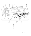
- a missile lance 1 intended to be installed on a vehicle comprises a frame 2 and a tube 3 intended to receive a missile 4.
- the tube 3 is orientable in site around a site axis 5 by elevating motor means (raising means 15 visible to the figure 4 ) and is substantially parallel to the horizontal 6 when no target pointing is envisaged.
- the rear portion AR of the tube includes a blast baffle of the type described in FR2934041 designed to deflect the missile fire gases upwards.
- the front part AV of the tube through which the missile fires when fired, is closed by a flap 7 which can swing forward around a hinge 11 secured to the lower part of the tube 3 and parallel to the axis of site 5.
- the flap 7 has on one of its slices, oriented vertically when the tube is closed, a first ramp 7a. On the face of this ramp 7a facing the outside of the tube, can roll a first caster 16a fixed to a first end 8a of a lever 8.
- a second end 8b of the lever 8 comprises a second caster 16b which is intended to roll along a second ramp 3a integral with the tube 3 and oriented longitudinally with respect to the tube 3.
- the ends 8a and 8b of the lever 8 could slide without a roller on the outer face 7a of the flap 7 and on the tube 3.
- the lever 8 has between its two ends 8a and 8b a pivot connection 9 secured to the frame 2 and parallel to the site axis 5.
- the V-shaped lever 8 comprising two branches 8c and 8d forming an angle between them and at the intersection of which the pivot connection 9 is located.
- an adjusting means 10 makes it possible to adjust the distance D separating the two ends 8a and 8b of the lever 8.
- the branches 8a and 8b are therefore independent of each other and articulated each at the level of pivot 9 to allow the angular approximation of these two branches by the adjusting means 10.
- This adjustment means 10 may comprise means conventionally known to those skilled in the art such as threaded rods extending from each leg with steps inverted relative to each other and interconnected by a threaded tube.
- the distance D will be chosen so that each of the ends 8a and 8b of the lever 8 is in contact with the ramps 3a and 7a when the tube is horizontal with the flap 7 closing the front of the tube 3.
- the tube 3 begins to pivot about its axis of site 5 bringing the front part AV of the tube above the horizontal axis 6 passing through the axis of site 5.
- the support of the tube 3 at the level of the second 8b end of the lever 8 is gradually relieved.
- the second end 8b of the lever 8 moves longitudinally towards the front of the tube 3 along the second ramp 3a as the angle of elevation of the tube increases, which also decreases the support of the first end 8a of the lever 8 on the flap 7 (the two branches 8c and 8d being integral with each other).
- a resilient means 11a such as a spring the flap 7 then opens by swinging downwardly as the first end 8a of the lever pivots downwardly rolling along the first ramp 7a which limits the opening stroke of the flap.
- the skilled person can overcome the use of an elastic means at the flap. In this case the tilting of the flap 7 will be due simply to the effect of gravity.
- Dashed is represented at the figure 2 a wall 77 representing the position occupied by a front wall of a trunk according to the prior art. It will be noted that for the elevation angle according to figure 2 which is of the order of 8 °, so relatively low, the opening of the tube is completely clear while for the same angle the wall 77 still significantly hinders the opening of the tube.
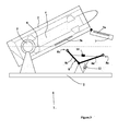
- the tube 3 continues to rise in elevation by means of elevation 15 comprising a jack.
- the ends 8a and 8b lever 8 are no longer in contact with the tube 3 or with the flap 7.
- the invention thus also allows missile fire at high elevation angles.
- an orientation means 12 the lever such as a tension spring, can be placed between the lever 8 and the frame 2. This orientation means will rotate the lever 8 so as to bring its first end 8a of the chassis 2.
- lever 8 ensures both the complete opening and low site of a closure flap of a missile launcher and closing said shutter. No specific motorization is necessary to open or close the shutter 7. It is the pointing movement in site of the tube 3 which will control the opening or closing of the shutter 7.
Landscapes
- Engineering & Computer Science (AREA)
- General Engineering & Computer Science (AREA)
- Toys (AREA)
- Aiming, Guidance, Guns With A Light Source, Armor, Camouflage, And Targets (AREA)
Abstract
Description
- Le domaine technique de l'invention est celui des lance-missiles.
- Les lances missiles comportent au moins un tube destiné à recevoir un missile et à le guider durant la phase initiale de lancement du missile.
- Afin d'éviter l'intrusion volontaire ou accidentelle dans le tube d'éléments susceptibles de provoquer un disfonctionnement du lance missile, celui-ci est souvent contenu dans un coffre dont au moins une paroi située à l'avant du lance missile obstrue le tube comme en témoigne le brevet
FR2934041 - Ainsi, sur un tel lance missile, lors d'un tir, il convient d'orienter le tube selon un angle de site pour lequel l'ouverture du tube n'est plus obturée par la paroi. Le site de pointage minimum est donc dicté par la hauteur de la paroi qui ne peut être inférieure à la dimension de l'ouverture du tube ce qui peut être très contraignant pour certaines distances de tir pour lesquelles l'angle de site est réduit, par exemple les tirs à courte distance.
- L'invention a pour objet de résoudre ce problème de désobturation du tube pour un angle de site réduit.
- L'invention permet également de simplifier le mécanisme d'ouverture et de fermeture du tube, en permettant en particulier de ne pas utiliser de moyens moteurs dédiés à l'ouverture du tube.
- Ainsi, l'invention a pour objet un lance missile comportant un châssis et un tube destiné à lancer un missile, le tube étant orientable autour d'un axe de site par rapport au châssis, tube comportant au moins à l'une de ses extrémités au moins une articulation parallèle à l'axe de site, articulation destinée à permettre le basculement par rapport au tube d'au moins un volet obturant au moins partiellement le tube, le lance missile comporte au moins un levier comportant deux branches formant un angle, une liaison pivot solidaire du châssis et parallèle à l'axe de site étant positionnée à l'intersection des branches, une première extrémité du levier étant destinée à coulisser le long d'une face du volet orientée vers l'extérieur du tube quand celui-ci est fermé par le volet et une seconde extrémité du levier étant destinée à coulisser longitudinalement sur une face du tube.
- Avantageusement, le levier comporte un moyen de réglage de la distance séparant ses extrémités.
- Avantageusement, le lance missile comporte un moyen élastique ayant pour effet de favoriser le basculement du volet dans le sens de l'ouverture du tube.
- Avantageusement, la première extrémité du levier comporte une première roulette destinée à parcourir une première rampe solidaire d'une tranche du volet.
- Avantageusement, la seconde extrémité du levier comporte une seconde roulette destinée à parcourir une seconde rampe solidaire d'une face latérale du tube.
- Avantageusement, le lance missile comprend un moyen d'orientation interposé entre le levier et le châssis, moyen d'orientation ayant pour effet de faire pivoter le levier de façon à rapprocher la première extrémité du châssis.
- Avantageusement, le moyen d'orientation comporte au moins un ressort.
- L'invention sera mieux comprise à la lecture de la description jointe, description faire en référence aux dessins annexés, dessins dans lesquels :
- La
figure 1 représente un lance missile selon l'invention tube fermé. - La
figure 2 représente un lance missile selon l'invention tube ouvert au site le plus bas. - La
figure 3 représente un lance missile selon l'invention tube ouvert à un site élevé. - La
figure 4 représente une vue de trois quarts d'un lance missile selon l'invention tube ouvert. - Selon la
figure 1 , un lance missile 1 destiné à être installé sur un véhicule (véhicule non représenté) comporte un châssis 2 ainsi qu'un tube 3 destiné à recevoir un missile 4. Le tube 3 est orientable en site autour d'un axe de site 5 par un moyen moteur d'élévation (moyen d'élévation 15 visible à lafigure 4 ) et il est sensiblement parallèle à l'horizontale 6 lorsqu'aucun pointage de cible n'est envisagé. - La partie arrière AR du tube comporte un déflecteur 20 de souffle du type décrit dans
FR2934041 - La partie avant AV du tube par laquelle le missile sort en cas de tir, est obturée par un volet 7 pouvant basculer vers l'avant autour d'une articulation 11 solidaire de la partie inférieure du tube 3 et parallèle à l'axe de site 5.
- Le volet 7 comporte sur une de ses tranches, orientée verticalement quand le tube est fermé, une première rampe de roulement 7a. Sur la face de cette rampe 7a orientée vers l'extérieur du tube, peut rouler une première roulette 16a fixée à une première extrémité 8a d'un levier 8. Une seconde extrémité 8b du levier 8 comporte une seconde roulette 16b qui est destinée à rouler le long d'une seconde rampe 3a solidaire du tube 3 et orientée longitudinalement par rapport au tube 3.
- Selon un autre mode de réalisation non représenté, les extrémités 8a et 8b du levier 8 pourraient coulisser sans roulette sur la face externe 7a du volet 7 et sur le tube 3.
- Le levier 8 comporte entre ses deux extrémités 8a et 8b une liaison pivot 9 solidaire du châssis 2 et parallèle à l'axe de site 5.
- Selon le mode de réalisation représenté, le levier 8 à une forme de V comportant deux branches 8c et 8d formant un angle entre elles et à l'intersection desquelles se situe la liaison pivot 9.
- Suivant le mode de réalisation décrit, un moyen de réglage 10 permet de régler la distance D séparant les deux extrémités 8a et 8b du levier 8. Les branches 8a et 8b sont donc indépendantes l'une de l'autre et articulées chacune au niveau du pivot 9 pour permettre le rapprochement angulaire de ces deux branches par le moyen de réglage 10.
- Ce moyen de réglage 10 pourra comporter des moyens classiquement connus de l'Homme du Métier tels que des tiges filetées partant de chaque branche avec des pas inversés l'un par rapport à l'autre et reliées entre elles par un tube taraudé.
- La distance D sera choisie de manière à ce que chacune des extrémités 8a et 8b du levier 8 soit en appui avec les rampes 3a et 7a lorsque le tube est à l'horizontale avec le volet 7 fermant l'avant du tube 3.
- On note ainsi que l'action d'appui du tube 3 sur la seconde extrémité 8b du levier provoque, par effet de bascule au niveau de la liaison pivot 9, l'appui de la première extrémité 8a du levier sur la face externe du volet 7 condamnant celui-ci à demeurer en position fermée.
- Selon la
figure 2 , le tube 3 entame un pivotement autour de son axe de site 5 amenant la partie avant AV du tube au-dessus de l'axe horizontal 6 passant par l'axe de site 5. L'appui du tube 3 au niveau de la seconde extrémité 8b du levier 8 est progressivement soulagé. - La seconde extrémité 8b du levier 8 se déplace longitudinalement vers l'avant du tube 3 le long de la seconde rampe 3a au fur et à mesure de l'augmentation de l'angle de site du tube, ce qui diminue aussi l'appui de la première extrémité 8a du levier 8 sur le volet 7 (les deux branches 8c et 8d étant solidaires l'une de l'autre).
- Sous l'action d'un moyen élastique 11a tel qu'un ressort le volet 7 s'ouvre alors en basculant vers le bas au fur et à mesure que la première extrémité 8a du levier pivote vers le bas en roulant le long de la première rampe 7a qui limite la course d'ouverture du volet.
- Selon un autre mode de réalisation, l'Homme du Métier pourra s'affranchir de l'usage d'un moyen élastique au niveau du volet. Dans ce cas le basculement du volet 7 sera dû simplement à l'effet de la gravité.
- En pointillés est représentée à la
figure 2 une paroi 77 représentant la position occupée par une paroi avant d'un coffre selon l'art antérieur. On notera que pour l'angle de site selon lafigure 2 qui est de l'ordre de 8°, donc relativement faible, l'ouverture du tube est totalement dégagée alors que pour le même angle la paroi 77 entrave encore significativement l'ouverture du tube. - On voit donc que l'invention permet le tir d'un missile avec un pointage faible. Selon les
figures 3 et4 , le tube 3 poursuit son élévation en site grâce au moyen d'élévation 15 comportant un vérin. Les extrémités 8a et 8b du levier 8 ne sont plus en contact ni avec le tube 3 ni avec le volet 7. - L'invention permet donc également le tir de missile à des angles d'élévation importants.
- On notera à la
figure 3 qu'un moyen d'orientation 12, du levier tel qu'un ressort de traction, pourra être placé entre le levier 8 et le châssis 2. Ce moyen d'orientation fera pivoter le levier 8 de façon à rapprocher sa première extrémité 8a du châssis 2. - Ceci permet, lorsque le tube 3 redescend à site horizontal, que la seconde extrémité 8b roule d'abord sur la seconde rampe 3a, fixée sur une face latérale du tube 3, pour ensuite permettre la remontée du volet 7 par roulement de la première extrémité 8a du levier sur la première rampe 7a jusqu'à fermeture complète du tube 3.
- Ainsi le levier 8 permet d'assurer à la fois l'ouverture complète et à site faible d'un volet de fermeture d'un tube lance-missile et la fermeture dudit volet. Aucune motorisation spécifique n'est nécessaire pour ouvrir ou fermer le volet 7. C'est le mouvement de pointage en site du tube 3 qui va commander l'ouverture ou la fermeture du volet 7.
Claims (7)
- Lance missile (1) comportant un châssis (2) et un tube (3) destiné à lancer un missile (4), le tube (3) étant orientable autour d'un axe (5) de site par rapport au châssis (2), tube (3) comportant au moins à l'une de ses extrémités au moins une articulation (11) parallèle à l'axe (5) de site, articulation (11) destinée à permettre le basculement par rapport au tube (3) d'au moins un volet (7) obturant au moins partiellement le tube (3), lance missile (1) caractérisé en ce qu'il comporte au moins un levier (8) comportant deux branches (8c et 8d) formant un angle, une liaison pivot (9) solidaire du châssis (2) et parallèle à l'axe (5) de site étant positionnée à l'intersection des branches (8c et 8d), une première extrémité (8a) du levier (8) étant destinée à coulisser le long d'une face (7a) du volet (7) orientée vers l'extérieur du tube (3) quand celui-ci est fermé par le volet (7) et une seconde extrémité du levier (8) étant destinée à coulisser longitudinalement sur une face (7a) du tube (3).
- Lance missile (1) selon la revendication 1, caractérisé en ce que le levier (8) comporte un moyen de réglage (10) de la distance séparant ses extrémités (8a et 8b).
- Lance missile (1) selon une des revendications 1 ou 2, caractérisé en ce qu'il comporte un moyen élastique (11a) ayant pour effet de favoriser le basculement du volet (7) dans le sens de l'ouverture du tube (3).
- Lance missile (1) selon une des revendications 1 à 3, caractérisé en ce que la première extrémité (8a) du levier (8) comporte une première roulette (16a) destinée à parcourir une première rampe (7a) solidaire d'une tranche du volet (7).
- Lance missile (1) selon une des revendications 1 à 4, caractérisé en ce que la seconde extrémité (8b) du levier (8) comporte une seconde roulette (16b) destinée à parcourir une seconde rampe (3a) solidaire d'une face latérale du tube (3).
- Lance missile (1) selon une des revendications 1 à 5, caractérisé en ce qu'il comprend un moyen d'orientation (12) interposé entre le levier (8) et le châssis (2), moyen d'orientation (12) ayant pour effet de faire pivoter le levier (8) de façon à rapprocher la première extrémité (8a) du châssis (2).
- Lance missile (1) selon la revendication 6, caractérisé en ce que le moyen d'orientation (12) comporte au moins un ressort (12).
Priority Applications (1)
| Application Number | Priority Date | Filing Date | Title |
|---|---|---|---|
| PL15186723T PL3001135T3 (pl) | 2014-09-26 | 2015-09-24 | Wyrzutnia pocisków |
Applications Claiming Priority (1)
| Application Number | Priority Date | Filing Date | Title |
|---|---|---|---|
| FR1402191A FR3026479B1 (fr) | 2014-09-26 | 2014-09-26 | Lance missile |
Publications (2)
| Publication Number | Publication Date |
|---|---|
| EP3001135A1 true EP3001135A1 (fr) | 2016-03-30 |
| EP3001135B1 EP3001135B1 (fr) | 2016-12-07 |
Family
ID=52589426
Family Applications (1)
| Application Number | Title | Priority Date | Filing Date |
|---|---|---|---|
| EP15186723.1A Active EP3001135B1 (fr) | 2014-09-26 | 2015-09-24 | Lance missile |
Country Status (6)
| Country | Link |
|---|---|
| EP (1) | EP3001135B1 (fr) |
| DK (1) | DK3001135T3 (fr) |
| ES (1) | ES2612437T3 (fr) |
| FR (1) | FR3026479B1 (fr) |
| IL (1) | IL241805B (fr) |
| PL (1) | PL3001135T3 (fr) |
Families Citing this family (3)
| Publication number | Priority date | Publication date | Assignee | Title |
|---|---|---|---|---|
| FR3058789B1 (fr) * | 2016-11-15 | 2018-11-02 | Nexter Systems | Systeme de tir de projectile |
| FR3062717B1 (fr) | 2017-02-07 | 2021-01-01 | Nexter Systems | Boitier destine a etre dispose sur un vehicule et systeme d'arme comprenant un tel boitier. |
| DE102024126925A1 (de) * | 2024-09-19 | 2026-03-19 | Rheinmetall Air Defence Ag | Militärisches Fahrzeug |
Citations (4)
| Publication number | Priority date | Publication date | Assignee | Title |
|---|---|---|---|---|
| GB256741A (en) * | 1925-06-11 | 1926-08-19 | Whitehead Torpedo Company Ltd | Improvements in or relating to launching or ejecting tubes for automobile torpedoes |
| JPH0561689U (ja) * | 1992-01-16 | 1993-08-13 | 三菱電機株式会社 | キャニスタ蓋開放機構装置 |
| RU2182305C2 (ru) * | 1995-11-08 | 2002-05-10 | Военно-морская академия имени Адмирала Флота Советского Союза Н.Г.Кузнецова | Подводный торпедный аппарат |
| FR2934041A1 (fr) | 2008-07-17 | 2010-01-22 | Dcns | Systeme d'armes, notamment pour missiles, destine a etre integre dans une plate-forme de combat et plate-forme de combat correspondante |
-
2014
- 2014-09-26 FR FR1402191A patent/FR3026479B1/fr active Active
-
2015
- 2015-09-24 IL IL241805A patent/IL241805B/en active IP Right Grant
- 2015-09-24 ES ES15186723.1T patent/ES2612437T3/es active Active
- 2015-09-24 PL PL15186723T patent/PL3001135T3/pl unknown
- 2015-09-24 DK DK15186723.1T patent/DK3001135T3/en active
- 2015-09-24 EP EP15186723.1A patent/EP3001135B1/fr active Active
Patent Citations (4)
| Publication number | Priority date | Publication date | Assignee | Title |
|---|---|---|---|---|
| GB256741A (en) * | 1925-06-11 | 1926-08-19 | Whitehead Torpedo Company Ltd | Improvements in or relating to launching or ejecting tubes for automobile torpedoes |
| JPH0561689U (ja) * | 1992-01-16 | 1993-08-13 | 三菱電機株式会社 | キャニスタ蓋開放機構装置 |
| RU2182305C2 (ru) * | 1995-11-08 | 2002-05-10 | Военно-морская академия имени Адмирала Флота Советского Союза Н.Г.Кузнецова | Подводный торпедный аппарат |
| FR2934041A1 (fr) | 2008-07-17 | 2010-01-22 | Dcns | Systeme d'armes, notamment pour missiles, destine a etre integre dans une plate-forme de combat et plate-forme de combat correspondante |
Also Published As
| Publication number | Publication date |
|---|---|
| EP3001135B1 (fr) | 2016-12-07 |
| IL241805B (en) | 2018-12-31 |
| DK3001135T3 (en) | 2017-01-23 |
| FR3026479A1 (fr) | 2016-04-01 |
| FR3026479B1 (fr) | 2016-09-02 |
| ES2612437T3 (es) | 2017-05-16 |
| PL3001135T3 (pl) | 2017-05-31 |
Similar Documents
| Publication | Publication Date | Title |
|---|---|---|
| EP1985960B1 (fr) | Dispositif de séparation des maillons d'une bande d'emport de munitions | |
| EP3001135B1 (fr) | Lance missile | |
| EP2870427B1 (fr) | Dispositif de lancement de cibles pour le tir sportif à départ instantané de la cible | |
| EP0592344B1 (fr) | Appareils pour le lancement de cibles dites pigeon d'argile | |
| WO2011138342A1 (fr) | Appareil pour le lancement de cibles | |
| FR2972423A1 (fr) | Procede et systeme de lancement d'un satellite | |
| EP0797755B1 (fr) | Appareil pour le lancement en double de cibles dites pigeons d'argile | |
| EP3450363A1 (fr) | Quai sécurisé de déchargement des déchets depuis un véhicule dans un centre de stockage | |
| EP0877910B1 (fr) | Appareil lanceur de cibles pour l'exercice du tir aux armes a feu | |
| FR2472163A1 (fr) | Appareil destine a lever et transporter des munitions d'artillerie | |
| EP3070203B1 (fr) | Système de chargement, de déchargement et de pose sur une voie ferrée d'un appareil de voie ferrée | |
| EP3179194B1 (fr) | Dispositif de manutention d'obus pour pièce d'artillerie | |
| EP2906901A1 (fr) | Dispositif de lancement de cibles | |
| WO2011138341A1 (fr) | Machines de lancement de cibles | |
| EP2992293B1 (fr) | Véhicule équipé d'un dispositif de protection d'ouvrant assurant une optimisation du gabarit d'ouverture | |
| FR2930817A1 (fr) | Systeme d'obturation d'un conduit d'evacuation des gaz d'un lanceur de missiles | |
| EP3867591B1 (fr) | Magasin pour arme de gros calibre et tourelle equipee d'un tel magasin | |
| FR2552218A1 (fr) | Mortier capable d'etre monte sur un vehicule | |
| EP2884216B1 (fr) | Dispositif d'alimentation en obus | |
| CH374317A (fr) | Jouet simulant le tir d'un avion sur un but à terre ou sur un bateau | |
| FR2965611A1 (fr) | Lanceur de cibles pour le tir | |
| WO2012080491A1 (fr) | Dispositif pour lancer des cibles pour le tir | |
| FR3047556A1 (fr) | Dispositif d'approvisionnement en obus et artillerie comprenant un tel dispositif | |
| FR2704055A1 (fr) | Arme de guerre à élément actif à redressement autonome. | |
| FR2706027A1 (fr) | Dispositif pour le relevage d'une cible comportant au moins une semelle de maintien en position debout. |
Legal Events
| Date | Code | Title | Description |
|---|---|---|---|
| PUAI | Public reference made under article 153(3) epc to a published international application that has entered the european phase |
Free format text: ORIGINAL CODE: 0009012 |
|
| AK | Designated contracting states |
Kind code of ref document: A1 Designated state(s): AL AT BE BG CH CY CZ DE DK EE ES FI FR GB GR HR HU IE IS IT LI LT LU LV MC MK MT NL NO PL PT RO RS SE SI SK SM TR |
|
| AX | Request for extension of the european patent |
Extension state: BA ME |
|
| 17P | Request for examination filed |
Effective date: 20160331 |
|
| RBV | Designated contracting states (corrected) |
Designated state(s): AL AT BE BG CH CY CZ DE DK EE ES FI FR GB GR HR HU IE IS IT LI LT LU LV MC MK MT NL NO PL PT RO RS SE SI SK SM TR |
|
| GRAP | Despatch of communication of intention to grant a patent |
Free format text: ORIGINAL CODE: EPIDOSNIGR1 |
|
| INTG | Intention to grant announced |
Effective date: 20160726 |
|
| RIC1 | Information provided on ipc code assigned before grant |
Ipc: F41F 3/077 20060101AFI20160715BHEP |
|
| GRAS | Grant fee paid |
Free format text: ORIGINAL CODE: EPIDOSNIGR3 |
|
| GRAA | (expected) grant |
Free format text: ORIGINAL CODE: 0009210 |
|
| AK | Designated contracting states |
Kind code of ref document: B1 Designated state(s): AL AT BE BG CH CY CZ DE DK EE ES FI FR GB GR HR HU IE IS IT LI LT LU LV MC MK MT NL NO PL PT RO RS SE SI SK SM TR |
|
| REG | Reference to a national code |
Ref country code: GB Ref legal event code: FG4D Free format text: NOT ENGLISH |
|
| REG | Reference to a national code |
Ref country code: AT Ref legal event code: REF Ref document number: 852125 Country of ref document: AT Kind code of ref document: T Effective date: 20161215 Ref country code: CH Ref legal event code: EP |
|
| REG | Reference to a national code |
Ref country code: IE Ref legal event code: FG4D Free format text: LANGUAGE OF EP DOCUMENT: FRENCH |
|
| REG | Reference to a national code |
Ref country code: DE Ref legal event code: R096 Ref document number: 602015000929 Country of ref document: DE |
|
| REG | Reference to a national code |
Ref country code: DK Ref legal event code: T3 Effective date: 20170119 |
|
| REG | Reference to a national code |
Ref country code: NL Ref legal event code: FP |
|
| PG25 | Lapsed in a contracting state [announced via postgrant information from national office to epo] |
Ref country code: LV Free format text: LAPSE BECAUSE OF FAILURE TO SUBMIT A TRANSLATION OF THE DESCRIPTION OR TO PAY THE FEE WITHIN THE PRESCRIBED TIME-LIMIT Effective date: 20161207 |
|
| REG | Reference to a national code |
Ref country code: SE Ref legal event code: TRGR |
|
| REG | Reference to a national code |
Ref country code: LT Ref legal event code: MG4D |
|
| PG25 | Lapsed in a contracting state [announced via postgrant information from national office to epo] |
Ref country code: GR Free format text: LAPSE BECAUSE OF FAILURE TO SUBMIT A TRANSLATION OF THE DESCRIPTION OR TO PAY THE FEE WITHIN THE PRESCRIBED TIME-LIMIT Effective date: 20170308 Ref country code: LT Free format text: LAPSE BECAUSE OF FAILURE TO SUBMIT A TRANSLATION OF THE DESCRIPTION OR TO PAY THE FEE WITHIN THE PRESCRIBED TIME-LIMIT Effective date: 20161207 |
|
| REG | Reference to a national code |
Ref country code: NO Ref legal event code: T2 Effective date: 20161207 |
|
| REG | Reference to a national code |
Ref country code: AT Ref legal event code: MK05 Ref document number: 852125 Country of ref document: AT Kind code of ref document: T Effective date: 20161207 |
|
| REG | Reference to a national code |
Ref country code: ES Ref legal event code: FG2A Ref document number: 2612437 Country of ref document: ES Kind code of ref document: T3 Effective date: 20170516 |
|
| PG25 | Lapsed in a contracting state [announced via postgrant information from national office to epo] |
Ref country code: HR Free format text: LAPSE BECAUSE OF FAILURE TO SUBMIT A TRANSLATION OF THE DESCRIPTION OR TO PAY THE FEE WITHIN THE PRESCRIBED TIME-LIMIT Effective date: 20161207 Ref country code: RS Free format text: LAPSE BECAUSE OF FAILURE TO SUBMIT A TRANSLATION OF THE DESCRIPTION OR TO PAY THE FEE WITHIN THE PRESCRIBED TIME-LIMIT Effective date: 20161207 |
|
| PG25 | Lapsed in a contracting state [announced via postgrant information from national office to epo] |
Ref country code: CZ Free format text: LAPSE BECAUSE OF FAILURE TO SUBMIT A TRANSLATION OF THE DESCRIPTION OR TO PAY THE FEE WITHIN THE PRESCRIBED TIME-LIMIT Effective date: 20161207 Ref country code: EE Free format text: LAPSE BECAUSE OF FAILURE TO SUBMIT A TRANSLATION OF THE DESCRIPTION OR TO PAY THE FEE WITHIN THE PRESCRIBED TIME-LIMIT Effective date: 20161207 Ref country code: IS Free format text: LAPSE BECAUSE OF FAILURE TO SUBMIT A TRANSLATION OF THE DESCRIPTION OR TO PAY THE FEE WITHIN THE PRESCRIBED TIME-LIMIT Effective date: 20170407 Ref country code: SK Free format text: LAPSE BECAUSE OF FAILURE TO SUBMIT A TRANSLATION OF THE DESCRIPTION OR TO PAY THE FEE WITHIN THE PRESCRIBED TIME-LIMIT Effective date: 20161207 Ref country code: RO Free format text: LAPSE BECAUSE OF FAILURE TO SUBMIT A TRANSLATION OF THE DESCRIPTION OR TO PAY THE FEE WITHIN THE PRESCRIBED TIME-LIMIT Effective date: 20161207 |
|
| REG | Reference to a national code |
Ref country code: FR Ref legal event code: PLFP Year of fee payment: 3 |
|
| PG25 | Lapsed in a contracting state [announced via postgrant information from national office to epo] |
Ref country code: BG Free format text: LAPSE BECAUSE OF FAILURE TO SUBMIT A TRANSLATION OF THE DESCRIPTION OR TO PAY THE FEE WITHIN THE PRESCRIBED TIME-LIMIT Effective date: 20170307 Ref country code: AT Free format text: LAPSE BECAUSE OF FAILURE TO SUBMIT A TRANSLATION OF THE DESCRIPTION OR TO PAY THE FEE WITHIN THE PRESCRIBED TIME-LIMIT Effective date: 20161207 Ref country code: PT Free format text: LAPSE BECAUSE OF FAILURE TO SUBMIT A TRANSLATION OF THE DESCRIPTION OR TO PAY THE FEE WITHIN THE PRESCRIBED TIME-LIMIT Effective date: 20170407 Ref country code: SM Free format text: LAPSE BECAUSE OF FAILURE TO SUBMIT A TRANSLATION OF THE DESCRIPTION OR TO PAY THE FEE WITHIN THE PRESCRIBED TIME-LIMIT Effective date: 20161207 |
|
| REG | Reference to a national code |
Ref country code: DE Ref legal event code: R097 Ref document number: 602015000929 Country of ref document: DE |
|
| PLBE | No opposition filed within time limit |
Free format text: ORIGINAL CODE: 0009261 |
|
| STAA | Information on the status of an ep patent application or granted ep patent |
Free format text: STATUS: NO OPPOSITION FILED WITHIN TIME LIMIT |
|
| 26N | No opposition filed |
Effective date: 20170908 |
|
| PG25 | Lapsed in a contracting state [announced via postgrant information from national office to epo] |
Ref country code: SI Free format text: LAPSE BECAUSE OF FAILURE TO SUBMIT A TRANSLATION OF THE DESCRIPTION OR TO PAY THE FEE WITHIN THE PRESCRIBED TIME-LIMIT Effective date: 20161207 |
|
| PG25 | Lapsed in a contracting state [announced via postgrant information from national office to epo] |
Ref country code: MC Free format text: LAPSE BECAUSE OF FAILURE TO SUBMIT A TRANSLATION OF THE DESCRIPTION OR TO PAY THE FEE WITHIN THE PRESCRIBED TIME-LIMIT Effective date: 20161207 |
|
| REG | Reference to a national code |
Ref country code: IE Ref legal event code: MM4A |
|
| PG25 | Lapsed in a contracting state [announced via postgrant information from national office to epo] |
Ref country code: LU Free format text: LAPSE BECAUSE OF NON-PAYMENT OF DUE FEES Effective date: 20170924 |
|
| PG25 | Lapsed in a contracting state [announced via postgrant information from national office to epo] |
Ref country code: IE Free format text: LAPSE BECAUSE OF NON-PAYMENT OF DUE FEES Effective date: 20170924 |
|
| REG | Reference to a national code |
Ref country code: FR Ref legal event code: PLFP Year of fee payment: 4 |
|
| PG25 | Lapsed in a contracting state [announced via postgrant information from national office to epo] |
Ref country code: MT Free format text: LAPSE BECAUSE OF FAILURE TO SUBMIT A TRANSLATION OF THE DESCRIPTION OR TO PAY THE FEE WITHIN THE PRESCRIBED TIME-LIMIT Effective date: 20161207 |
|
| PG25 | Lapsed in a contracting state [announced via postgrant information from national office to epo] |
Ref country code: HU Free format text: LAPSE BECAUSE OF FAILURE TO SUBMIT A TRANSLATION OF THE DESCRIPTION OR TO PAY THE FEE WITHIN THE PRESCRIBED TIME-LIMIT; INVALID AB INITIO Effective date: 20150924 |
|
| PG25 | Lapsed in a contracting state [announced via postgrant information from national office to epo] |
Ref country code: CY Free format text: LAPSE BECAUSE OF FAILURE TO SUBMIT A TRANSLATION OF THE DESCRIPTION OR TO PAY THE FEE WITHIN THE PRESCRIBED TIME-LIMIT Effective date: 20161207 |
|
| PG25 | Lapsed in a contracting state [announced via postgrant information from national office to epo] |
Ref country code: MK Free format text: LAPSE BECAUSE OF FAILURE TO SUBMIT A TRANSLATION OF THE DESCRIPTION OR TO PAY THE FEE WITHIN THE PRESCRIBED TIME-LIMIT Effective date: 20161207 |
|
| PG25 | Lapsed in a contracting state [announced via postgrant information from national office to epo] |
Ref country code: AL Free format text: LAPSE BECAUSE OF FAILURE TO SUBMIT A TRANSLATION OF THE DESCRIPTION OR TO PAY THE FEE WITHIN THE PRESCRIBED TIME-LIMIT Effective date: 20161207 |
|
| PGFP | Annual fee paid to national office [announced via postgrant information from national office to epo] |
Ref country code: NL Payment date: 20250820 Year of fee payment: 11 |
|
| REG | Reference to a national code |
Ref country code: CH Ref legal event code: U11 Free format text: ST27 STATUS EVENT CODE: U-0-0-U10-U11 (AS PROVIDED BY THE NATIONAL OFFICE) Effective date: 20251001 |
|
| PGFP | Annual fee paid to national office [announced via postgrant information from national office to epo] |
Ref country code: FI Payment date: 20250820 Year of fee payment: 11 |
|
| PGFP | Annual fee paid to national office [announced via postgrant information from national office to epo] |
Ref country code: DE Payment date: 20250820 Year of fee payment: 11 Ref country code: DK Payment date: 20250820 Year of fee payment: 11 |
|
| PGFP | Annual fee paid to national office [announced via postgrant information from national office to epo] |
Ref country code: NO Payment date: 20250825 Year of fee payment: 11 |
|
| PGFP | Annual fee paid to national office [announced via postgrant information from national office to epo] |
Ref country code: PL Payment date: 20250820 Year of fee payment: 11 Ref country code: TR Payment date: 20250901 Year of fee payment: 11 Ref country code: IT Payment date: 20250820 Year of fee payment: 11 |
|
| PGFP | Annual fee paid to national office [announced via postgrant information from national office to epo] |
Ref country code: BE Payment date: 20250820 Year of fee payment: 11 Ref country code: GB Payment date: 20250822 Year of fee payment: 11 |
|
| PGFP | Annual fee paid to national office [announced via postgrant information from national office to epo] |
Ref country code: FR Payment date: 20250820 Year of fee payment: 11 |
|
| PGFP | Annual fee paid to national office [announced via postgrant information from national office to epo] |
Ref country code: SE Payment date: 20250820 Year of fee payment: 11 |
|
| PGFP | Annual fee paid to national office [announced via postgrant information from national office to epo] |
Ref country code: CH Payment date: 20251001 Year of fee payment: 11 |
|
| PGFP | Annual fee paid to national office [announced via postgrant information from national office to epo] |
Ref country code: ES Payment date: 20251001 Year of fee payment: 11 |