EP0797755B1 - Appareil pour le lancement en double de cibles dites pigeons d'argile - Google Patents
Appareil pour le lancement en double de cibles dites pigeons d'argile Download PDFInfo
- Publication number
- EP0797755B1 EP0797755B1 EP95942226A EP95942226A EP0797755B1 EP 0797755 B1 EP0797755 B1 EP 0797755B1 EP 95942226 A EP95942226 A EP 95942226A EP 95942226 A EP95942226 A EP 95942226A EP 0797755 B1 EP0797755 B1 EP 0797755B1
- Authority
- EP
- European Patent Office
- Prior art keywords
- launcher
- launchers
- launching
- axis
- pivoting platform
- Prior art date
- Legal status (The legal status is an assumption and is not a legal conclusion. Google has not performed a legal analysis and makes no representation as to the accuracy of the status listed.)
- Expired - Lifetime
Links
Images

Classifications
-
- F—MECHANICAL ENGINEERING; LIGHTING; HEATING; WEAPONS; BLASTING
- F41—WEAPONS
- F41J—TARGETS; TARGET RANGES; BULLET CATCHERS
- F41J9/00—Moving targets, i.e. moving when fired at
- F41J9/16—Clay-pigeon targets; Clay-disc targets
- F41J9/18—Traps or throwing-apparatus therefor
-
- F—MECHANICAL ENGINEERING; LIGHTING; HEATING; WEAPONS; BLASTING
- F41—WEAPONS
- F41J—TARGETS; TARGET RANGES; BULLET CATCHERS
- F41J9/00—Moving targets, i.e. moving when fired at
- F41J9/16—Clay-pigeon targets; Clay-disc targets
- F41J9/18—Traps or throwing-apparatus therefor
- F41J9/30—Traps or throwing-apparatus therefor characterised by using a magazine of targets
Definitions
- the subject of the invention is an apparatus for launching into doubled with targets called clay pigeons.
- the launcher should launch simultaneously two targets called clay pigeons. Shooting this doubling must be carried out according to very precise standards identical or different flights of the targets, as to the angle spacing other their respective trajectory, as for their departure, their altitude etc.
- EP-0592.344 A1 Apparatus for launching targets for shooting whose speed and projection distance are variable, from type using a rotating barrel on which are loaded moving targets; moving targets are superimposed on each other the others in columns, held by tubes or rollers vertical arranged between a bored upper retaining plate or having radiating arms for storing targets mobile and a lower retaining plate reamed at each column of targets or having radiating arms between each target column; said lower plate being in upper and parallel position with respect to a base plate fixed which has a single bore to allow passage moving targets which are received on a launch placed in front of an ejection arm, one or more motors ensuring barrel rotation and arm movement ejection characterized by the fact that the launch pad is consisting of a fixed launch pad and a launch pad mobile and articulated along a pivot axis substantially transverse whose upper faces of said ramps are one same height lower and parallel to the trajectory of the entire ejection arm.
- the launcher is composed of a chassis which is mounted mobile on a base, movable vertically and horizontally. On the chassis two independent launch arms are mounted, each near a food store, said stores can be loaded with targets of different sizes.
- a mobile tray vertically feeds the targets towards the target launch common to both launch arms.
- a gearbox operates both the arming of the arms and the feeding of targets by a set of springs, belts, chains and links.
- GB-A-2.189.154 (LAWRENCE): This patent, the description of which is taken from the preamble of claim 1, describes a launcher so-called clay pigeon targets.
- the target launcher includes a chassis which can move both vertically and horizontally randomly.
- Two launch arms independent with each a removable clay pigeon barrel with barrels of the same type including clay pigeons of different sizes are installed on the chassis.
- a pneumatic lifting device allows the clay pigeons on top of barrels at arms level launch.
- Two springs are fixed at one end by a mobile hanging device and two levers to each other end.
- the gear can rotate the launch arms in order to energize the two launch springs.
- the gear can also rotate the barrels, removable springs hooks and check the vertical movements of the chassis as well as the movements horizontal of the support carrying the chassis.
- this patent describes a launcher unique specific for the double with all the disadvantages that wants to avoid invention.
- the apparatus according to the invention tends to solve all of these disadvantages.
- the apparatus for launching doubled targets say clay pigeons is of the type using two barrels target feed rotary, one or more motors ensuring barrel rotation and arm movements ejection characterized by the fact that it is composed of two launchers with the same characteristics, arranged side by side, one being the symmetric of the other with respect to a plane of vertical symmetry that would separate them, the two launchers have their launch pad and their launch arms, each at a level different, they are mounted integral with a swash plate, said swash plate is mounted on an axis of oscillation of a base plate which forms the fixed base of said device.
- the swash plate is provided with adjustment means which adjust the spacing angle between the launch axis of one launcher relative to the launch axis of the other launcher so as to define the angle of separation between the two target trajectories.
- Each launcher has the axis of rotation of the launch arm which is coaxial with the pivot axis of said launcher.
- the axis of pivoting of each launcher is located on the plate oscillation common to both launchers.
- the means for adjusting the angle of separation between the axis of launch of one launcher and the other launch axis of the other symmetrical launcher are preset holes provided for this purpose on the oscillation plate common to the two launchers. Each series of holes is arranged on the side opposite the pivot axis of the launcher.
- the swash plate common to the two launchers is two levels, one level for a launcher, another level for the other symmetrical launcher so that the ramps of launch and one's launch arms can overlap compared to those of the other launcher.
- the swash plate is actuated in oscillation on its axis by a gear motor.
- Said oscillation gear motor is connected by a connecting pin, connecting rod and swash plate.
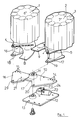
- Figure 1 is a schematic view of the apparatus seen in exploded to highlight the arrangement of the two launchers, one of which is symmetrical with respect to the other as well as their liaison bodies.
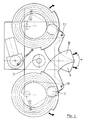
- Figure 2 is a plan view of the apparatus showing evidence the two launchers, the main organs and the means adjusting and actuating said adjustments; in this mode of achievement, the trajectory of the double is simple.
- the axes longitudinal launch pads of launchers are in a same axis.
- Figure 3 is a plan view of the apparatus showing evidence the two launchers, the main organs and the means adjusting and actuating said adjustments; in this mode of achievement, the trajectories of the targets of the double are different.
- the longitudinal axes of the launching ramps which are overlap are not in the same axis and form between them a trajectory spacing angle in the horizontal plane.
- the apparatus for launching doubled as shown in Figure 1 is of the type using two barrels 1 and 2 supply of targets 3.
- One or more motors, not shown in Figure 1 rotates the barrels 1, 2 and ejection arm movements 4 and 5.
- the device is characterized by the fact that it is composed of made of two 6,7 launchers with the same characteristics techniques arranged side by side. One being the symmetric of the other, in relation to a vertical plane of symmetry which would separate.
- the two launchers 6 and 7 have their launching ramp 8 and 9 each arranged at a different level. These two launchers 6 and 7 are mounted integral on an oscillating plate 10.
- This plate oscillating 10 is mounted on an oscillation axis 11 of a plate base 12 which forms the fixed base of said device.
- This tray base 12 is fixed by fixing means, by means of holes 13, on civil engineering.
- the swash plate 10 is provided with adjustment means 14 and 15 which make it possible to adjust the angle of separation between the axis of launching a launcher 6 relative to the launch axis of the other launcher 7 which is symmetrical to it, so that define the angle of separation between the two trajectories of targets.
- the launch axis of a launcher corresponds to the axis longitudinal of the launching pad 8 or 9 of each launcher 6.7.
- Each launcher 6,7 has its axis of rotation of its arm launch 4 or 5 which is coaxial with the pivot axis 16 or 17 of said launcher 6 or 7.
- the pivot axis 16 or 17 of each launcher 6 or 7 is located on the oscillation plate 10. This axis pivot through a hole arranged at the level of the part front of the sole 18.19 of the two launchers 6 and 7.
- This sole 18 and 19 is fixed by its orifice by a fixing means located in the corresponding hole 29.20 located on the front part of the swing plate 10.
- the means of adjusting 14 and 15 of the angle of separation between the launch axis of a launcher 6 and the other launch axis of the other symmetrical launcher 7 are preset holes 14 and 15 provided for this purpose on the oscillation plate 10, common to the two launchers 6 and 7.
- Each series of holes 14 and 15 is arranged on the side opposite to the pivot axis 16 or 17 of the launcher 6 or 7.
- the swash plate 10, common to the two launchers 6 and 7 is on two levels.
- the two levels are represented by the arrows 21 which highlight a level shift on the swash plate 10.
- the swash plate 10 is actuated in oscillation on its axis 11 by a geared motor 22.
- This geared motor 22 is connected, by a connecting pin 23 disposed at the end of a link 24, a link allowing the oscillation of said plate 10.
- This link rod 24 is provided of a known system allowing oscillation adjustment.
- Figures 1 and 2 show some other adjusting or blocking members of the respective position of the two launchers 6 and 7.
- Adjustable levers 25 and 26 allow fine adjustment of the position of the launchers 6 and 7 on the swash plate 10.
- a tightening button 27 or 28 makes it possible to immobilize the launchers 6 and 7 after adjusting the trajectories.
- FIG. 2 thus makes it possible to clearly visualize the two launchers 6 and 7 which have been oriented by their pivot axis 16,17 of so that their launching pad 8 and 9 is in one launch axis. There is thus only one trajectory, simple trajectory for the two targets. The spacing angle is no. The two launchers 6,7 are in the same alignment.
Landscapes
- Engineering & Computer Science (AREA)
- General Engineering & Computer Science (AREA)
- Toys (AREA)
- Catching Or Destruction (AREA)
- Pharmaceuticals Containing Other Organic And Inorganic Compounds (AREA)
- Organic Low-Molecular-Weight Compounds And Preparation Thereof (AREA)
- Agricultural Chemicals And Associated Chemicals (AREA)
Description
- Demande de brevet déposée le 2 septembre 1993 sous le n° 93.10640 : appareil du type pour le lancement des pigeons d'argile ou cibles mobiles pour le tir sportif utilisant un barillet rotatif d'alimentation en cibles mobiles, un ou plusieurs moteurs assurant la rotation du barillet rotatif et le mouvement du bras d'éjection, un moyen d'actionnement en rotation assure la rotation de l'ensemble sur le support qui lui est ancré au sol, caractérisé par le fait que l'ensemble barillet, rampe de lancement, moteurs, est monté articulé sur un support d'assemblage qui vient s'emmancher sur un axe vertical solidaire du support d'ancrage ; un moteur assure, par une came et une biellette d'articulation, les réglages de positionnement horizontal de l'axe de tir et de l'ouverture de l'angle horizontal.
Claims (8)
- Appareil pour le lancement en doublé de cibles dites pigeons d'argile du type utilisant deux barillets rotatifs d'alimentation en cibles, un ou plusieurs moteurs assurant la rotation des barillets et les mouvements des bras d'éjection caractérisé par le fait
qu'il est composé de deux lanceurs (6,7) ayant les mêmes caractéristiques techniques, disposés côte à côte, l'un étant le symétrique de l'autre par rapport à un plan de symétrie vertical qui les sépare, les deux lanceurs (6,7) ont leur rampe de lancement (8 et 9) et leur bras de lancement (4,5), chacun à un niveau différent, ils sont montés solidaires d'un plateau oscillant (10), ledit plateau oscillant (10) est monté sur un axe d'oscillation (11) d'un plateau d'embase (12) qui forme le socle fixe dudit appareil. - Appareil selon la revendication 1, caractérisé par le fait
que le plateau oscillant (10) est pourvu de moyens de réglage (14 et 15) qui permettent de régler l'angle d'écartement entre l'axe de lancement d'un lanceur (6) par rapport à l'axe de lancement de l'autre lanceur (7) de manière à définir l'angle d'écartement α entre les deux trajectoires des cibles de chaque lanceur. - Appareil selon la revendication 1, caractérisé par le fait
que chaque lanceur (6,7) a l'axe de rotation du bras de lancement (4 ou 5) qui est coaxial avec l'axe de pivotement (16 ou 17) dudit lanceur (6 ou 7). L'axe de pivotement (16 ou 17) de chaque lanceur (6 ou 7) est situé sur le plateau d'oscillation (10) commun aux deux lanceurs. - Appareil selon la revendication 2 caractérisé par le fait
que les moyens de réglage (14 et 15) de l'angle d'écartement entre l'axe de lancement d'un lanceur (6) et l'autre axe de lancement de l'autre lanceur (7) symétrique sont des trous de préréglage (14 et 15) prévus à cet effet sur le plateau d'oscillation (10) commun aux deux lanceurs (6 et 7) ; chaque série de trous (14 et 15) est disposée du côté opposé à l'axe de pivotement (16 ou 17) du lanceur (6 ou 7). - Appareil selon la revendication 1 caractérisé par le fait
que le plateau oscillant (10) commun aux deux lanceurs (6 et 7) est à deux niveaux, un niveau pour un lanceur (6), un autre niveau pour l'autre lanceur (7) symétrique et ce, de manière à ce que les rampes de lancement (8,9) et les bras de lancement (4 et 5) de l'un puissent se superposer par rapport à ceux de l'autre lanceur (6 ou 7). - Appareil selon la revendication 1 caractérisé par le fait
que le plateau oscillant (10) est actionné en oscillation sur son axe (11) par un motoréducteur (22); ledit motoréducteur (22) d'oscillation est raccordé par un axe de raccordement (23), bielle et plateau oscillant. - Appareil selon la revendication 6 caractérisé par le fait
que le motoréducteur (22) est raccordé, par un axe de raccordement (23) disposé à l'extrémité d'une biellette (24); cette biellette permet l'oscillation dudit plateau (10) ; cette biellette (24) est pourvue d'un système connu permettant le réglage d'oscillation. - Appareil selon la revendication 7 caractérisé par le fait
que des leviers réglables (25 et 26) permettent le réglage fin de la position des lanceurs (6 et 7) sur le plateau oscillant (10) ; un bouton de serrage (27 ou 28) permet d'immobiliser les lanceurs (6 et 7) après avoir réglé les trajectoires.
Applications Claiming Priority (3)
| Application Number | Priority Date | Filing Date | Title |
|---|---|---|---|
| FR9415277 | 1994-12-13 | ||
| FR9415277A FR2728067A1 (fr) | 1994-12-13 | 1994-12-13 | Appareil pour le lancement en double de cibles dites pigeons d'argile |
| PCT/FR1995/001625 WO1996018864A1 (fr) | 1994-12-13 | 1995-12-08 | Appareil pour le lancement en double de cibles dites pigeons d'argile |
Publications (2)
| Publication Number | Publication Date |
|---|---|
| EP0797755A1 EP0797755A1 (fr) | 1997-10-01 |
| EP0797755B1 true EP0797755B1 (fr) | 1999-06-16 |
Family
ID=9469953
Family Applications (1)
| Application Number | Title | Priority Date | Filing Date |
|---|---|---|---|
| EP95942226A Expired - Lifetime EP0797755B1 (fr) | 1994-12-13 | 1995-12-08 | Appareil pour le lancement en double de cibles dites pigeons d'argile |
Country Status (7)
| Country | Link |
|---|---|
| US (1) | US5871003A (fr) |
| EP (1) | EP0797755B1 (fr) |
| AT (1) | ATE181419T1 (fr) |
| AU (1) | AU4349496A (fr) |
| DE (1) | DE69510376D1 (fr) |
| FR (1) | FR2728067A1 (fr) |
| WO (1) | WO1996018864A1 (fr) |
Families Citing this family (16)
| Publication number | Priority date | Publication date | Assignee | Title |
|---|---|---|---|---|
| CA2388284A1 (fr) * | 2000-02-04 | 2001-08-09 | Mattel, Inc. | Jouet lanceur de disques |
| US7637255B1 (en) | 2007-02-28 | 2009-12-29 | Freeland John P | Target launcher having versatile mounting configurations |
| US7958877B2 (en) * | 2008-01-31 | 2011-06-14 | Tom Lalor | Launching system for launching target and retrieval devices |
| US8677983B2 (en) * | 2008-07-08 | 2014-03-25 | Canterbury Trap International Limited | Trench clay target trap machine |
| US20100102512A1 (en) * | 2008-10-28 | 2010-04-29 | Barak Dar | Automatic Shooting Sequence Controller |
| FR2959803B1 (fr) * | 2010-05-05 | 2015-01-09 | Laporte Holding | Machine pour le lancement de cibles |
| FR2959804B1 (fr) * | 2010-05-05 | 2012-05-25 | Laporte Holding | Dispositif de distribution de cibles |
| FR2979142B1 (fr) * | 2011-08-18 | 2015-01-09 | Laporte Holding | Machine de lancement de cibles pour le tir a l'arc a chargement par gravite |
| US9389050B1 (en) * | 2012-07-19 | 2016-07-12 | Xiao Ming Chen | Target throwing device |
| US10052544B2 (en) | 2014-09-09 | 2018-08-21 | Garza And Gowan Sports Equipment | Ball tossing apparatus and method |
| FR3030714B1 (fr) * | 2014-12-17 | 2017-01-13 | Laporte Holding | Machine pour le lancement de cibles et son procede de reglage |
| WO2019241719A1 (fr) * | 2018-06-14 | 2019-12-19 | Francez Stephen Edward | Équipement de lancement de cible volante |
| US10365072B1 (en) * | 2018-11-05 | 2019-07-30 | Cheh-Kang Liu | Trap wobbler |
| FR3100879B1 (fr) * | 2019-09-17 | 2022-04-15 | Laporte Holding | Dispositif de lancement de cibles |
| US10859349B1 (en) * | 2019-12-18 | 2020-12-08 | Cheh-Kang Liu | Micro switch adjustment structure of a throwing trap |
| FR3119451B1 (fr) * | 2021-01-29 | 2023-01-06 | Laporte Holding | Système de trois lanceurs de cibles |
Family Cites Families (12)
| Publication number | Priority date | Publication date | Assignee | Title |
|---|---|---|---|---|
| US3070082A (en) * | 1954-06-16 | 1962-12-25 | Olin Mathieson | Target throwing apparatus |
| US3119383A (en) * | 1958-06-12 | 1964-01-28 | Olin Mathieson | Target throwing apparatus |
| US3097635A (en) * | 1961-03-02 | 1963-07-16 | Carl R Freeman | Target throwing apparatus |
| US3304928A (en) * | 1964-03-31 | 1967-02-21 | George H Darrell | Rotary trap magazine with two-stage target feed |
| SE333695B (fr) * | 1969-10-21 | 1971-03-22 | I Hansen | |
| FR2238136B1 (fr) * | 1973-07-17 | 1976-06-18 | Laporte Sa | |
| DE2344483A1 (de) * | 1973-09-04 | 1975-03-13 | Spieth Ernst K Fa | Tontaubenwurfmaschine |
| US4048976A (en) * | 1975-06-12 | 1977-09-20 | Remington Arms Company, Inc. | Magazine assembly for tournament trap |
| WO1987001191A1 (fr) * | 1985-08-15 | 1987-02-26 | Brian Alexander Heffer | Magasin pour cibles |
| US4699116A (en) * | 1986-01-17 | 1987-10-13 | John Paul Freeland | Multiple arm target launcher |
| GB2189154B (en) * | 1986-04-15 | 1989-11-29 | Graham Howard Lawrence | Clay pigeon launcher |
| AU662444B2 (en) * | 1992-10-07 | 1995-08-31 | Societe Dite Laporte | Apparatus for launching movable discs or targets |
-
1994
- 1994-12-13 FR FR9415277A patent/FR2728067A1/fr active Granted
-
1995
- 1995-12-08 US US08/849,849 patent/US5871003A/en not_active Expired - Fee Related
- 1995-12-08 AT AT95942226T patent/ATE181419T1/de not_active IP Right Cessation
- 1995-12-08 AU AU43494/96A patent/AU4349496A/en not_active Abandoned
- 1995-12-08 WO PCT/FR1995/001625 patent/WO1996018864A1/fr active IP Right Grant
- 1995-12-08 EP EP95942226A patent/EP0797755B1/fr not_active Expired - Lifetime
- 1995-12-08 DE DE69510376T patent/DE69510376D1/de not_active Expired - Lifetime
Also Published As
| Publication number | Publication date |
|---|---|
| US5871003A (en) | 1999-02-16 |
| ATE181419T1 (de) | 1999-07-15 |
| WO1996018864A1 (fr) | 1996-06-20 |
| FR2728067B1 (fr) | 1997-02-07 |
| AU4349496A (en) | 1996-07-03 |
| EP0797755A1 (fr) | 1997-10-01 |
| DE69510376D1 (de) | 1999-07-22 |
| FR2728067A1 (fr) | 1996-06-14 |
Similar Documents
| Publication | Publication Date | Title |
|---|---|---|
| EP0797755B1 (fr) | Appareil pour le lancement en double de cibles dites pigeons d'argile | |
| FR2934458A1 (fr) | Machine de recolte de baies, en particulier machine a vendanger, pourvue d'un systeme de secouage, et commande de secouage mecatronique de ce systeme. | |
| EP0592344B1 (fr) | Appareils pour le lancement de cibles dites pigeon d'argile | |
| EP2567181A1 (fr) | Appareil pour le lancement de cibles | |
| FR2675893A1 (fr) | Appareil pour le lancement de plateaux ou cibles mobiles pour le tir sportif. | |
| FR2597704A1 (fr) | Materiel de recolte mecanique de fruits. | |
| CA2008159A1 (fr) | Dispositif de mise en position inclinee d'une sous-munition sous parachute | |
| EP3966517A1 (fr) | Machine de lancement de cibles | |
| FR2744210A1 (fr) | Appareil lanceur de cibles pour l'exercice du tir aux armes a feu | |
| FR2529793A1 (fr) | Garniture d'orientation pour simulateur lanceur de balles, notamment de tennis ou de football | |
| FR2472662A1 (fr) | Dispositif pour le reglage du niveau de coupe d'un rabot a charbon ou d'un engin analogue | |
| FR2625696A1 (fr) | Dispositif d'alimentation en rivets ou analogues, notamment pour machines de rivetage | |
| EP3234494B1 (fr) | Machine pour le lancement de cibles et son procédé de réglage | |
| EP0146551B1 (fr) | Appareil porte-cible pour entrainement au tir | |
| EP0406140B1 (fr) | Machine agricole munie de bras porte-rotors télescopiques | |
| FR2639053A1 (fr) | Manipulateur pour engins de travaux publics et machine munie d'un tel manipulateur et servant au traitement d'une chaussee | |
| EP1222845B1 (fr) | Procédé pour séparer des mottes cubiques, dispositif pour la mise en oeuvre du procédé et machine de plantation de plantes en mottes comportant un tel dispositf | |
| FR2733043A1 (fr) | Appareil pour le lancement de plateaux ou cibles mobiles pour le tir sportif | |
| FR2539157A1 (fr) | Trancheuse a fleche | |
| FR2524136A1 (fr) | Mecanisme pour alimenter en munitions une arme a double tube | |
| FR2683696A1 (fr) | Pulverisateur en v a commande de repliement hydraulique des trains de disques. | |
| FR2787181A1 (fr) | Appareil pour le lancement de cibles du type plateau d'argile | |
| FR2709543A1 (fr) | Appareil pour le lancement de plateaux ou cibles mobiles pour le tir sportif. | |
| FR2709542A1 (fr) | Rampe de lancement mobile et articulée pour appareil de lancement de cibles. | |
| FR2514985A1 (fr) | Rampe epandeuse pour distributeur d'engrais |
Legal Events
| Date | Code | Title | Description |
|---|---|---|---|
| PUAI | Public reference made under article 153(3) epc to a published international application that has entered the european phase |
Free format text: ORIGINAL CODE: 0009012 |
|
| 17P | Request for examination filed |
Effective date: 19970610 |
|
| AK | Designated contracting states |
Kind code of ref document: A1 Designated state(s): AT BE CH DE DK ES FR GB GR IE IT LI LU MC NL PT SE |
|
| 17Q | First examination report despatched |
Effective date: 19971013 |
|
| GRAG | Despatch of communication of intention to grant |
Free format text: ORIGINAL CODE: EPIDOS AGRA |
|
| GRAG | Despatch of communication of intention to grant |
Free format text: ORIGINAL CODE: EPIDOS AGRA |
|
| GRAH | Despatch of communication of intention to grant a patent |
Free format text: ORIGINAL CODE: EPIDOS IGRA |
|
| GRAH | Despatch of communication of intention to grant a patent |
Free format text: ORIGINAL CODE: EPIDOS IGRA |
|
| GRAA | (expected) grant |
Free format text: ORIGINAL CODE: 0009210 |
|
| AK | Designated contracting states |
Kind code of ref document: B1 Designated state(s): AT BE CH DE DK ES FR GB GR IE IT LI LU MC NL PT SE |
|
| PG25 | Lapsed in a contracting state [announced via postgrant information from national office to epo] |
Ref country code: SE Free format text: THE PATENT HAS BEEN ANNULLED BY A DECISION OF A NATIONAL AUTHORITY Effective date: 19990616 Ref country code: NL Free format text: LAPSE BECAUSE OF FAILURE TO SUBMIT A TRANSLATION OF THE DESCRIPTION OR TO PAY THE FEE WITHIN THE PRESCRIBED TIME-LIMIT Effective date: 19990616 Ref country code: IT Free format text: LAPSE BECAUSE OF FAILURE TO SUBMIT A TRANSLATION OF THE DESCRIPTION OR TO PAY THE FEE WITHIN THE PRE;WARNING: LAPSES OF ITALIAN PATENTS WITH EFFECTIVE DATE BEFORE 2007 MAY HAVE OCCURRED AT ANY TIME BEFORE 2007. THE CORRECT EFFECTIVE DATE MAY BE DIFFERENT FROM THE ONE RECORDED.SCRIBED TIME-LIMIT Effective date: 19990616 Ref country code: GR Free format text: LAPSE BECAUSE OF NON-PAYMENT OF DUE FEES Effective date: 19990616 Ref country code: ES Free format text: THE PATENT HAS BEEN ANNULLED BY A DECISION OF A NATIONAL AUTHORITY Effective date: 19990616 Ref country code: AT Free format text: LAPSE BECAUSE OF FAILURE TO SUBMIT A TRANSLATION OF THE DESCRIPTION OR TO PAY THE FEE WITHIN THE PRESCRIBED TIME-LIMIT Effective date: 19990616 |
|
| REF | Corresponds to: |
Ref document number: 181419 Country of ref document: AT Date of ref document: 19990715 Kind code of ref document: T |
|
| REG | Reference to a national code |
Ref country code: CH Ref legal event code: EP |
|
| REF | Corresponds to: |
Ref document number: 69510376 Country of ref document: DE Date of ref document: 19990722 |
|
| REG | Reference to a national code |
Ref country code: IE Ref legal event code: FG4D Free format text: FRENCH |
|
| PG25 | Lapsed in a contracting state [announced via postgrant information from national office to epo] |
Ref country code: PT Free format text: LAPSE BECAUSE OF FAILURE TO SUBMIT A TRANSLATION OF THE DESCRIPTION OR TO PAY THE FEE WITHIN THE PRESCRIBED TIME-LIMIT Effective date: 19990916 Ref country code: DK Free format text: LAPSE BECAUSE OF FAILURE TO SUBMIT A TRANSLATION OF THE DESCRIPTION OR TO PAY THE FEE WITHIN THE PRESCRIBED TIME-LIMIT Effective date: 19990916 |
|
| PG25 | Lapsed in a contracting state [announced via postgrant information from national office to epo] |
Ref country code: DE Free format text: LAPSE BECAUSE OF FAILURE TO SUBMIT A TRANSLATION OF THE DESCRIPTION OR TO PAY THE FEE WITHIN THE PRESCRIBED TIME-LIMIT Effective date: 19990917 |
|
| GBT | Gb: translation of ep patent filed (gb section 77(6)(a)/1977) |
Effective date: 19991014 |
|
| NLV1 | Nl: lapsed or annulled due to failure to fulfill the requirements of art. 29p and 29m of the patents act | ||
| PG25 | Lapsed in a contracting state [announced via postgrant information from national office to epo] |
Ref country code: LU Free format text: LAPSE BECAUSE OF NON-PAYMENT OF DUE FEES Effective date: 19991208 |
|
| PGFP | Annual fee paid to national office [announced via postgrant information from national office to epo] |
Ref country code: FR Payment date: 19991221 Year of fee payment: 5 |
|
| PGFP | Annual fee paid to national office [announced via postgrant information from national office to epo] |
Ref country code: GB Payment date: 19991223 Year of fee payment: 5 |
|
| PG25 | Lapsed in a contracting state [announced via postgrant information from national office to epo] |
Ref country code: LI Free format text: LAPSE BECAUSE OF NON-PAYMENT OF DUE FEES Effective date: 19991231 Ref country code: CH Free format text: LAPSE BECAUSE OF NON-PAYMENT OF DUE FEES Effective date: 19991231 Ref country code: BE Free format text: LAPSE BECAUSE OF NON-PAYMENT OF DUE FEES Effective date: 19991231 |
|
| PLBE | No opposition filed within time limit |
Free format text: ORIGINAL CODE: 0009261 |
|
| STAA | Information on the status of an ep patent application or granted ep patent |
Free format text: STATUS: NO OPPOSITION FILED WITHIN TIME LIMIT |
|
| 26N | No opposition filed | ||
| BERE | Be: lapsed |
Owner name: LAPORTE BALL TRAP Effective date: 19991231 |
|
| PG25 | Lapsed in a contracting state [announced via postgrant information from national office to epo] |
Ref country code: MC Free format text: LAPSE BECAUSE OF NON-PAYMENT OF DUE FEES Effective date: 20000630 |
|
| REG | Reference to a national code |
Ref country code: IE Ref legal event code: FD4D |
|
| PG25 | Lapsed in a contracting state [announced via postgrant information from national office to epo] |
Ref country code: GB Free format text: LAPSE BECAUSE OF NON-PAYMENT OF DUE FEES Effective date: 20001208 |
|
| GBPC | Gb: european patent ceased through non-payment of renewal fee |
Effective date: 20001208 |
|
| PG25 | Lapsed in a contracting state [announced via postgrant information from national office to epo] |
Ref country code: FR Free format text: LAPSE BECAUSE OF NON-PAYMENT OF DUE FEES Effective date: 20010831 |
|
| REG | Reference to a national code |
Ref country code: FR Ref legal event code: ST |