EP3000999A1 - Breather chamber of internal combustion engine - Google Patents
Breather chamber of internal combustion engine Download PDFInfo
- Publication number
- EP3000999A1 EP3000999A1 EP15186875.9A EP15186875A EP3000999A1 EP 3000999 A1 EP3000999 A1 EP 3000999A1 EP 15186875 A EP15186875 A EP 15186875A EP 3000999 A1 EP3000999 A1 EP 3000999A1
- Authority
- EP
- European Patent Office
- Prior art keywords
- cam chain
- chamber
- breather
- crankshaft
- breather chamber
- Prior art date
- Legal status (The legal status is an assumption and is not a legal conclusion. Google has not performed a legal analysis and makes no representation as to the accuracy of the status listed.)
- Granted
Links
Images


Classifications
-
- F—MECHANICAL ENGINEERING; LIGHTING; HEATING; WEAPONS; BLASTING
- F01—MACHINES OR ENGINES IN GENERAL; ENGINE PLANTS IN GENERAL; STEAM ENGINES
- F01M—LUBRICATING OF MACHINES OR ENGINES IN GENERAL; LUBRICATING INTERNAL COMBUSTION ENGINES; CRANKCASE VENTILATING
- F01M13/00—Crankcase ventilating or breathing
- F01M13/04—Crankcase ventilating or breathing having means for purifying air before leaving crankcase, e.g. removing oil
-
- F—MECHANICAL ENGINEERING; LIGHTING; HEATING; WEAPONS; BLASTING
- F01—MACHINES OR ENGINES IN GENERAL; ENGINE PLANTS IN GENERAL; STEAM ENGINES
- F01L—CYCLICALLY OPERATING VALVES FOR MACHINES OR ENGINES
- F01L1/00—Valve-gear or valve arrangements, e.g. lift-valve gear
- F01L1/02—Valve drive
- F01L1/022—Chain drive
-
- F—MECHANICAL ENGINEERING; LIGHTING; HEATING; WEAPONS; BLASTING
- F01—MACHINES OR ENGINES IN GENERAL; ENGINE PLANTS IN GENERAL; STEAM ENGINES
- F01L—CYCLICALLY OPERATING VALVES FOR MACHINES OR ENGINES
- F01L1/00—Valve-gear or valve arrangements, e.g. lift-valve gear
- F01L1/02—Valve drive
- F01L1/04—Valve drive by means of cams, camshafts, cam discs, eccentrics or the like
- F01L1/047—Camshafts
-
- F—MECHANICAL ENGINEERING; LIGHTING; HEATING; WEAPONS; BLASTING
- F01—MACHINES OR ENGINES IN GENERAL; ENGINE PLANTS IN GENERAL; STEAM ENGINES
- F01M—LUBRICATING OF MACHINES OR ENGINES IN GENERAL; LUBRICATING INTERNAL COMBUSTION ENGINES; CRANKCASE VENTILATING
- F01M13/00—Crankcase ventilating or breathing
- F01M13/04—Crankcase ventilating or breathing having means for purifying air before leaving crankcase, e.g. removing oil
- F01M13/0405—Crankcase ventilating or breathing having means for purifying air before leaving crankcase, e.g. removing oil arranged in covering members apertures, e.g. caps
-
- F—MECHANICAL ENGINEERING; LIGHTING; HEATING; WEAPONS; BLASTING
- F02—COMBUSTION ENGINES; HOT-GAS OR COMBUSTION-PRODUCT ENGINE PLANTS
- F02F—CYLINDERS, PISTONS OR CASINGS, FOR COMBUSTION ENGINES; ARRANGEMENTS OF SEALINGS IN COMBUSTION ENGINES
- F02F1/00—Cylinders; Cylinder heads
- F02F1/24—Cylinder heads
-
- F—MECHANICAL ENGINEERING; LIGHTING; HEATING; WEAPONS; BLASTING
- F02—COMBUSTION ENGINES; HOT-GAS OR COMBUSTION-PRODUCT ENGINE PLANTS
- F02F—CYLINDERS, PISTONS OR CASINGS, FOR COMBUSTION ENGINES; ARRANGEMENTS OF SEALINGS IN COMBUSTION ENGINES
- F02F7/00—Casings, e.g. crankcases or frames
- F02F7/0043—Arrangements of mechanical drive elements
-
- F—MECHANICAL ENGINEERING; LIGHTING; HEATING; WEAPONS; BLASTING
- F01—MACHINES OR ENGINES IN GENERAL; ENGINE PLANTS IN GENERAL; STEAM ENGINES
- F01M—LUBRICATING OF MACHINES OR ENGINES IN GENERAL; LUBRICATING INTERNAL COMBUSTION ENGINES; CRANKCASE VENTILATING
- F01M13/00—Crankcase ventilating or breathing
- F01M13/04—Crankcase ventilating or breathing having means for purifying air before leaving crankcase, e.g. removing oil
- F01M2013/0461—Crankcase ventilating or breathing having means for purifying air before leaving crankcase, e.g. removing oil with a labyrinth
Landscapes
- Engineering & Computer Science (AREA)
- Mechanical Engineering (AREA)
- General Engineering & Computer Science (AREA)
- Chemical & Material Sciences (AREA)
- Combustion & Propulsion (AREA)
- Lubrication Details And Ventilation Of Internal Combustion Engines (AREA)
- Cylinder Crankcases Of Internal Combustion Engines (AREA)
Abstract
Description
- The present invention relates to a breather chamber of an internal combustion engine which suppresses an increase in the size of the internal combustion engine.
- Some internal combustion engines including a cam chain chamber disposed along a side portion of a cylinder block portion which intersects the direction of a crankshaft and including a looped cam chain for transmitting the power of the crankshaft to a camshaft provided in a cylinder head have a structure in which a breather chamber is provided outside a rotation locus of the cam chain. Such a structure is disclosed in, for example,
JP 2008-248806 Figures 1 to 4 ). - However, in the structure disclosed in
JP 2008-248806 - The present invention has been made in view of the above-described conventional technique, and an object of at least the preferred embodiments of the present invention is to provide a breather chamber of an internal combustion engine which includes a looped cam chain for transmitting the power of a crankshaft to a camshaft provided in a cylinder head and includes a cam chain chamber disposed along a side portion of a cylinder block portion intersecting the direction of the crankshaft and in which the breather chamber having a large size can be formed while an increase in the size of the internal combustion engine is suppressed.
- To solve the above-described problem, a first aspect of the present invention provides a breather chamber of an internal combustion engine including: a looped cam chain for transmitting power from a horizontally disposed crankshaft to a camshaft provided in a cylinder head; and a cam chain chamber disposed along a side portion of a cylinder block portion, the side portion intersecting a direction of the crankshaft,
in which the breather chamber is located on a side of a plane formed by a rotation locus of the cam chain in the direction of the crankshaft in the cam chain chamber. - A second aspect of the present invention provides the breather chamber of the internal combustion engine according to the first aspect, in which the cam chain chamber is formed by attaching a cam chain chamber cover to the side portion of the cylinder block portion, and a partitioning member for dividing the breather chamber from the cam chain chamber is formed of a flat plate and attached to an inside of the cam chain chamber cover.
- A third aspect of the present invention provides the breather chamber of the internal combustion engine according to the first or second aspect, in which the breather chamber has an inlet provided in a lower portion of the cam chain chamber and an outlet provided in an upper portion of the cam chain chamber.
- A fourth aspect of the present invention provides the breather chamber of the internal combustion engine according to the third aspect, in which a rib protruding from the cam chain chamber cover into the breather chamber is formed to slope downward along an inner surface of the cam chain chamber cover between the inlet and the outlet.
- A fifth aspect of the present invention provides the breather chamber of the internal combustion engine according to any one of the first to fourth aspects, in which the internal combustion engine is an in-vehicle engine, the crankshaft is directed in a longitudinal direction of a vehicle, the cam chain chamber is disposed on a front surface of the internal combustion engine, and a front portion of the cam chain chamber is divided to form the breather chamber.
- In the breather chamber of the internal combustion engine according to the first aspect of the invention, since a large space located on the side of the plane formed by the rotation locus of the cam chain in the direction of the crankshaft is utilized to provide the breather chamber, the breather chamber having a large size can be formed while an increase in the size of the internal combustion engine is suppressed.
- In the second aspect of the invention, in addition to the effect of the first aspect of the invention, with a simple configuration, the breather chamber can be formed between the cam chain chamber cover and the partitioning member, and the cam chain chamber in which oil is scattered can be divided from the breather chamber. Further, since the partitioning member is formed of a flat plate, an increase in the size of the internal combustion engine with respect to the direction of the crankshaft can be suppressed.
- In the third aspect of the invention, in addition to the effect of the first or second aspect of the invention, a layout which allows oil to be easily discharged from the breather chamber can be obtained using the vertical height of the cam chain chamber.
- In the fourth aspect of the invention, in addition to the effect of the third aspect of the invention, oil separated from the breather gas which adheres to the rib is caused to flow downward, and oil is easily discharged from the breather chamber.
- In the fifth aspect of the invention, in addition to the effect of any one of the first to fourth aspects of the invention, even in the case where the internal combustion engine with the crankshaft directed in the longitudinal direction of a vehicle is mounted on a vehicle having space limitations with respect to the longitudinal direction thereof, partitioning a front-side space of the cam chain chamber with respect to the direction of the crankshaft suppresses an increase in the size of the internal combustion engine with respect to the longitudinal direction of the vehicle while achieving a large volume of the breather chamber, and facilitates the installation of the internal combustion engine.
- A preferred embodiment of the invention will now be described by way of example only and with reference to the accompanying drawings, in which:
-
Fig. 1 is a right side view of a principal part of a motorcycle including a power unit in which a breather chamber of an internal combustion engine according to one embodiment of the present invention is provided; -
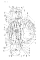
Fig. 2 is a front view of the power unit as seen along arrows II-II inFig. 1 ; -
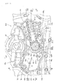
Fig. 3 is a vertical cross-sectional view of a principal part of a front portion of the power unit taken in the direction of a crankshaft as seen along arrows III-III inFigs. 2 ,4 , and5 ; -
Fig. 4 is a front view of a portion around an opening of the cam chain chamber with a cam chain chamber cover ofFig. 2 removed, a partitioning member being shown at a predetermined position, as seen along arrows IV-IV inFig. 3 ; and -
Fig. 5 is a front view of a portion around the opening of the cam chain chamber as seen along arrows V-V inFig. 3 . - A breather chamber of an internal combustion engine according to one embodiment of the present invention will be described with reference to
Figs. 1 to 5 . - In the appended claims and this specification, directions such as front, rear, left, right, upward, and downward directions are based on the normal orientation of a vehicle including a power unit in which the breather chamber of the internal combustion engine of the present embodiment is provided. In the present embodiment, a vehicle is a saddle-type vehicle such as a motorcycle.
- In the drawings, arrows FR, LH, RH, and UP indicate front, left, right, and upward directions, respectively.
-
Fig. 1 is a right side view of a principal part of amotorcycle 1 including apower unit 3 in which abreather chamber 7 of aninternal combustion engine 4 according to one embodiment of the present invention is provided. In themotorcycle 1 ofFig. 1 , abody cover 10 is indicated by a two-dot chain line in a simplified manner, part of which is omitted, and only a principal part is shown with an intake system, an exhaust system, a fuel system, and the like being omitted. - A
body frame 2 of themotorcycle 1 includes ahead pipe 20 by which afront fork 12 pivotally supporting afront wheel 11 is movably supported so that steering can be performed, amain frame 21 extending downwardly and rearwardly from thehead pipe 20,seat rails 22 extending upwardly and rearwardly from upper portions of rear ends of themain frame 21, and a back stay 23 connecting lower portions of rear ends of themain frame 21 and rear-side portions of theseat rails 22. - A
steering handlebar 13 is connected to an upper portion of thefront fork 12. Moreover, a front end portion of aswing arm 14 is movably supported by rear end portions of themain frame 21 to be vertically swingable, and arear wheel 15 which is a drive wheel is pivotally supported by a rear end portion of theswing arm 14. - Further, an unillustrated rear cushion unit is provided between the upper portions of the rear ends of the
main frame 21 and theswing arm 14, and ariding seat 16 is attached to upper portions of theseat rails 22. - A
power unit 3 for driving therear wheel 15 is disposed in a space below themain frame 21. Thepower unit 3 is supported by themain frame 21 with a plurality ofhanger members 17 interposed therebetween. Anoutput shaft 32 of thepower unit 3 is connected to therear wheel 15 through adrive shaft 33 installed along theswing arm 14, and transmits rotational power to therear wheel 15. -
Fig. 2 is a front view of thepower unit 3 as seen along arrows II-II inFig. 1 . - As shown in
Figs. 1 and2 , thepower unit 3 includes the water-cooled, horizontally-opposed, six-cylinder, four-strokeinternal combustion engine 4, and atransmission 5 which changes the speed of the rotational power of theinternal combustion engine 4 and which is provided with a reverse transmission system for reversing the direction of rotation. - A shell of the
internal combustion engine 4 includes acrankcase 42, which includes aleft crankcase 42L and aright crankcase 42R; left andright cylinder heads right crankcases rear cover 44 connected to the left andright crankcases Fig. 1 ) - The
rear cover 44 is connected to the left andright crankcases right crankcases motorcycle 1, - It should be noted that left and right cylinder head covers 45L and 45R are respectively fastened to outer ends of the left and
right cylinder heads right cylinder heads sprockets camshafts - The left and
right crankcases crankcase 42, by which acrankshaft 31 horizontally disposed with an axis X thereof directed in the longitudinal direction of themotorcycle 1 is rotatably supported at mating surfaces of the left andright crankcases crank chamber 30 around thecrankshaft 31. - Further, the left and
right crankcases cylinder block portions crank chamber 30, respectively. Each of the left and rightcylinder block portions parallel cylinder bores 46a (seeFig. 3 ) formed therein through which unillustrated pistons connected to thecrankshaft 31 through unillustrated connecting rods in common are inserted. - In the left and
right crankcases crank chamber 30, amain shaft 51 and acounter shaft 52 of thetransmission 5 which are disposed parallel to thecrankshaft 31 and directed in the longitudinal direction of the vehicle are supported, and atransmission chamber 50 is demarcated. In the left andright crankcases transmission chamber 50, anoil pan portion 47 is formed. - A
clutch cover 53 disposed concentrically with themain shaft 51 of thetransmission 5 to cover an unillustrated clutch mechanism is attached to a rear surface of therear cover 44, and theoutput shaft 32 of thepower unit 3 protrudes from therear cover 44 toward the rear (seeFig. 1 ). - The
output shaft 32 is connected to the drive shaft 33 (seeFig. 1 ), which extends along theswing arm 14 and is connected to therear wheel 15, and transmits the rotational power of theinternal combustion engine 4 to therear wheel 15. - As shown in
Fig. 2 , a cam chain chamber opening 48 is provided to straddle left and right crankcase front walls 42La and 42Ra, which are front portions of the left andright crankcases crankshaft 31 to regions near the left andright cylinder heads - An opening
circumferential wall 48a protruding toward the front is formed on a circumferential edge of the cam chain chamber opening 48. A camchain chamber cover 49 is fastened to the openingcircumferential wall 48a with fasteningbolts 49b. Thus, the camchain chamber cover 49 closes the cam chain chamber opening 48 to close a front portion of thecrank chamber 30. - Moreover, a
transmission holder 55 is provided around themain shaft 51 and thecounter shaft 52 of thetransmission 5, which is disposed below thecrankshaft 31, ashift drum 54, and the like (the positions of the central axes thereof are shown inFig. 2 ), to be connected to the left andright crankcases transmission chamber 50. - The
transmission chamber 50 is formed from thetransmission holder 55 to insides of the left andright crankcases transmission 5. - The left and
right crankcases cam chain chambers Fig. 2 ) side portions of the respectivecylinder block portions crankshaft 31 to communicate with insides of the left andright cylinder heads chain chamber cover 49, together with the left and right crankcase front walls 42La and 42Ra, constitutes part of a front wall which covers the left and rightcam chain chambers - It should be noted that in
Fig. 2 , the camchain chamber cover 49 is shown with part of a left-side portion (right-side portion in the drawing) being cut away. A front side portion ("side portion" in the present invention) 46La of the leftcylinder block portion 46L and the leftcam chain chamber 63L located ahead of the front side portion 46La in the drawing are shown behind the cut-away portion in the drawing. Part of aleft cam chain 65L which extends in thecam chain chamber 63L is shown in the drawing. - Similarly, a front side portion ("side portion" in the present invention) 46Ra of the right
cylinder block portion 46R, a rightcam chain chamber 63R, and aright cam chain 65R are disposed behind a right-side portion (left-side portion in the drawing) of the camchain chamber cover 49. - The
cam chain 65L for transmitting the power of thecrankshaft 31 to theleft camshaft 61 L is passed through the leftcam chain chamber 63L and looped around adrive sprocket 64L for theleft camshaft 61 L fitted to a front-end side of thecrankshaft 31 and the drivensprocket 62L of thecamshaft 61 L of the left valve train provided in theleft cylinder head 43L. - Similarly, the
cam chain 65R for transmitting the power of thecrankshaft 31 to theright camshaft 61 R is passed through the rightcam chain chamber 63R and looped around adrive sprocket 64R for theright camshaft 61 R fitted to the front-end side of thecrankshaft 31 and the drivensprocket 62R of thecamshaft 61 R of the right valve train provided in theright cylinder head 43R. - These components drive the left and right valve trains. An inlet valve and an exhaust valve, both unillustrated, corresponding to each of the
cylinder bores 46a (seeFig. 3 ) are opened and closed with a predetermined timing in synchronization with the rotation of thecrankshaft 31. - It should be noted that a water
pump drive gear 31 a is also fitted to the front-end side of thecrankshaft 31 to mesh with a drivengear 56a of awater pump 56. - Specifically, as shown in
Fig. 2 , in the left andright crankcases cam chain chambers cylinder block portions crankshaft 31. The left and right crankcase front walls 42La and 42Ra have the cam chain chamber opening 48 which straddles both the left and right crankcase front walls 42La and 42Ra to include a region around thecrankshaft 31. The camchain chamber cover 49 is fastened to the openingcircumferential wall 48a, which protrudes forwardly from the circumferential edge of the cam chain chamber opening 48, to cover the left and rightcam chain chambers - As shown in
Fig. 3 , showing a vertical cross section of a principal part of a front portion of thepower unit 3 taken along the axis X of thecrankshaft 31 as seen along arrows III-III inFig. 2 , an outer circumferential edge of the camchain chamber cover 49 also has a covercircumferential wall 49a protruding to the rear, and the covercircumferential wall 49a is fastened to the openingcircumferential wall 48a withcover fastening bolts 49b (also seeFig. 4 ). - Accordingly, portions of the left and right
cam chain chambers chain chamber cover 49 have spaces larger than those of portions thereof covered with the left and right crankcase front walls 42La and 42Ra by an amount equal to an inside height of the camchain chamber cover 49, i.e., an amount approximately equal to the height of the covercircumferential wall 49a in the direction of the axis X of the crankshaft. - Accordingly, as shown in
Fig. 3 , in the present embodiment, in thecam chain chamber 63R on theright crankcase 42R side, a partitioningmember 71 formed of a flat plate is disposed on the front side of a plane P formed by a rotation locus L (seeFig. 4 ) of thecam chain 65R in the direction of thecrankshaft 31. Thus, thebreather chamber 7 is demarcated between the partitioningmember 71 and an inner surface (rear surface) 49g of the cam chain chamber cover 49 so as to be divided from thecam chain chamber 63R. - Specifically, a portion of the
cam chain chamber 63R which is covered with the camchain chamber cover 49 is formed by fastening the cam chain chamber cover 49 to the openingcircumferential wall 48a of the camchain chamber opening 48. Since the cam chain chamber cover 49 having the partitioningmember 71 attached to the inside (rear side) thereof is fastened, thebreather chamber 7 is formed on the front side of the plane P formed by the rotation locus L of theright cam chain 65R in the direction of thecrankshaft 31 to be divided from the rightcam chain chamber 63R. - Accordingly, since a large space in the cam chain chamber opening 48 which is located on the front side of the plane P formed by the rotation locus L of the right cam chain 65P in the direction of the
crankshaft 31 is utilized to provide thebreather chamber 7, thebreather chamber 7 having a large size is formed while an increase in the size of theinternal combustion engine 4 is suppressed. - In particular, even in the case where the
internal combustion engine 4 of thepower unit 3 is an in-vehicle engine which has thecrankshaft 31 directed in the longitudinal direction of the vehicle and which is mounted on a vehicle having space limitations with respect to the longitudinal direction, disposing thecam chain chambers crankcases internal combustion engine 4 and forming thebreather chamber 7 in the front portion of thecam chain chamber 63R by dividing a front-side space of the rightcam chain chamber 63R suppresses an increase in the size of theinternal combustion engine 4 with respect to the longitudinal direction of the vehicle while achieving a large volume of thebreather chamber 7, and facilitates the installation of theinternal combustion engine 4 of thepower unit 3. - Moreover, with a simple configuration in which the
partitioning member 71 formed of a flat plate is disposed, thebreather chamber 7 can be formed between the camchain chamber cover 49 and the partitioningmember 71, and thecam chain chamber 63R in which oil is scattered can be divided from thebreather chamber 7. Further, since the partitioningmember 71 is formed of a flat plate, an increase in the size of theinternal combustion engine 4 with respect to the direction of thecrankshaft 31 can be suppressed. - It should be noted that in the present embodiment, the partitioning
member 71 is attached to the cam chain chamber cover 49 by screwing, from the rear, partitioningmember fastening bolts 71 a into partitioningmember fastening bosses 49c (seeFig. 5 ) provided upright on theinner surface 49g of the cam chain chamber cover 49 toward the rear. However, the partitioningmember 71 may be attached to the openingcircumferential wall 48a such that when the camchain chamber cover 49 is fastened to the openingcircumferential wall 48a, the partitioningmember 71 and the camchain chamber cover 49 are fastened together. - In
Fig. 3 ,reference numeral 72 denotes a breather outlet flow path, which also serves as a downstream-side portion of thebreather chamber 7. An upstream side of the breatheroutlet flow path 72 is opened at a front end of the openingcircumferential wall 48a to communicate with abreather chamber outlet 7b provided in an upper portion of thecam chain chamber 63R, and a downstream side thereof extends in thecylinder block portion 46R to the rear to communicate with an outlet nozzle 73 directed outward. The outlet nozzle 73 communicates with an unillustrated air cleaner through an unillustrated breather return pipe. -
Fig. 4 shows a front surface around the cam chain chamber opening 48 with the cam chain chamber cover 49 inFig. 2 removed as seen along arrows IV-IV inFig. 3 . It should be noted that the partitioningmember 71 is shown at a predetermined position. - The partitioning
member 71 is located ahead of theright cam chain 65R (on a front side in the drawing) in the rightcam chain chamber 63R to be in contact with the inner circumference of the openingcircumferential wall 48a of the cam chain chamber opening 48 on the right crankcase front wall 42Ra side and with the circumference of thecrankshaft 31. In other words, the partitioningmember 71 is disposed on the front side of the plane P formed by the rotation locus L of theright cam chain 65R in the direction of thecrankshaft 31, and divides thebreather chamber 7 from the rightcam chain chamber 63R. - As shown in
Fig. 4 , thebreather chamber outlet 7b communicating with the breatheroutlet flow path 72 located in an upper portion of the rightcam chain chamber 63R and provided in the openingcircumferential wall 48a is formed in a right upper portion (left upper portion in the drawing) of thebreather chamber 7. - In
Fig. 4 ,reference numeral 71 b denotes partitioning member fastening holes 71 b which allow the partitioningmember fastening bolts 71 a for fastening the partitioningmember 71 to be inserted through the partitioningmember fastening bosses 49c provided upright on theinner surface 49g of the aforementioned cam chain chamber cover 49 inFig. 3 toward the rear. - Moreover, a top surface 48aa, straddling the left and right crankcase front walls 42La and 42Ra, of the opening
circumferential wall 48a of the cam chain chamber opening 48 serves as a mating surface to which the camchain chamber cover 49 is fastened. Thecover fastening bolts 49b (seeFig. 3 ) screwed into the cam chain chamber cover 49 from the front portion side (on a front side in the drawing) are indicated by two-dot chain lines inFig. 4 . -
Fig. 5 is a front view around the cam chain chamber opening 48a inFig. 2 as seen along arrows V-V inFig. 3 , with the cam chain chamber cover 49 being cut. The covercircumferential wall 49a provided on the outer circumference of the camchain chamber cover 49, the partitioningmember fastening bosses 49c provided to protrude from theinner surface 49g,ribs 49d, and a crankshaftcircumferential wall 49e surrounding thecrankshaft 31 are shown as a cross section perpendicular to the axis X of thecrankshaft 31. - The
breather chamber 7 is surrounded by the covercircumferential wall 49a and the crankshaftcircumferential wall 49e to be demarcated between the partitioningmember 71 and theinner surface 49g of the camchain chamber cover 49. Agap 49f is provided between the covercircumferential wall 49a and the crankshaftcircumferential wall 49e so that thebreather chamber 7 may communicate with the cam chain chamber opening 48 in a lower portion of thecam chain chamber 63R, and constitutes a breather chamber inlet ("inlet" in the present invention) 7a. - Moreover, in a right upper portion (left upper portion in the drawing) of the cover
circumferential wall 49a, the breather chamber outlet ("outlet" in the present invention) 7b overlapping an upstream end of the breatheroutlet flow path 72 provided in the openingcircumferential wall 48a and apassage 49h (seeFig. 3 ) allowing the inside of thebreather chamber 7 to communicate with thebreather chamber outlet 7b are formed. - Accordingly, breather gas flows into the
breather chamber inlet 7a from thecrank chamber 30 side through the left and rightcam chain chambers breather chamber 7 flows out from thebreather chamber outlet 7b into the breatheroutlet flow path 72, and is further sent from the outlet nozzle 73 through the unillustrated breather return pipe to the unillustrated air cleaner. - It should be noted that the
breather chamber inlet 7a is located in lower portions of the left and rightcam chain chambers breather chamber outlet 7b is located in an upper portion of the rightcam chain chamber 63R. Accordingly, breather gas flowing in through thebreather chamber inlet 7a flows toward thebreather chamber outlet 7b in thebreather chamber 7 as a rising stream. Accordingly, oil in liquid phase mixed in the breather gas is easily separated downward from the gas by the difference in weight between the oil and the gas. Further, oil flowing downward from thebreather chamber inlet 7a located at a lower position flows through thecam chain chambers Fig. 2 ) demarcated below thecrank chamber 30. - Thus, a layout which allows oil in breather gas to be easily discharged from the
breather chamber 7 is obtained by providing thebreather chamber 7 over the entire height of the cam chain chamber opening 48 using the vertical heights of thecam chain chambers - Moreover, as shown in
Fig. 5 , each of theribs 49d (seeFig. 3 ) protruding from theinner surface 49g of the cam chain chamber cover 49 into thebreather chamber 7 is formed to be inclined downward from an end connected to the openingcircumferential wall 48a or the crankshaftcircumferential wall 49e to an open end in thebreather chamber 7 along theinner surface 49g of the camchain chamber cover 49, as seen from the front surface. - Accordingly, while flowing toward the
breather chamber outlet 7b in thebreather chamber 7 as a rising stream, breather gas flowing in through thebreather chamber inlet 7a passes through a labyrinthine flow path formed by theribs 49d extended from the openingcircumferential wall 48a and the crankshaftcircumferential wall 49e. This facilitates the separation of oil from breather gas. Oil separated from breather gas tends to adhere to theribs 49d and flows downward toward the open ends of theribs 49d Thus, oil is easily discharged from thebreather chamber 7. - Hereinafter, characteristic configurations and advantageous effects of the
breather chamber 7 of theinternal combustion engine 4 of the present embodiment will be described together. - Specifically, in the
breather chamber 7 of theinternal combustion engine 4 including the left and right loopedcam chains crankshaft 31 to thecamshafts right cylinder heads cam chain chambers cylinder block portions crankshaft 31, thebreather chamber 7 is disposed on the front side of the plane P formed by the rotation locus L of theright cam chain 65R in the direction of thecrankshaft 31 in the rightcam chain chamber 63R. - Accordingly, since a large space located on the front side of the plane P formed by the rotation locus L of the
cam chain 65R in the direction of thecrankshaft 31 is utilized to provide thebreather chamber 7, thebreather chamber 7 having a large size can be formed while an increase in the size of theinternal combustion engine 4 is suppressed. - Moreover, the left and right
cam chain chambers cylinder block portions member 71 for dividing thebreather chamber 7 from the rightcam chain chamber 63R is formed of a flat plate and attached to the inside of the camchain chamber cover 49. - Accordingly, with a simple configuration, the
breather chamber 7 can be formed between the camchain chamber cover 49 and the partitioningmember 71, and thecam chain chambers breather chamber 7. Further, since the partitioningmember 71 is formed of a flat plate, an increase in the size of theinternal combustion engine 4 with respect to the direction of thecrankshaft 31 can be suppressed. - Moreover, the
breather chamber 7 has thebreather chamber inlet 7a provided in a lower portion of the rightcam chain chamber 63R and thebreather chamber outlet 7b provided in an upper portion of the rightcam chain chamber 63R. Thus, a layout which allows oil to be easily discharged from thebreather chamber 7 is obtained using the vertical height of thecam chain chamber 63R. - Moreover, the
ribs 49d protruding from the cam chain chamber cover 49 into thebreather chamber 7 are formed to slope downward along the inner surface of the cam chain chamber cover 49 between thebreather chamber inlet 7a and thebreather chamber outlet 7b. Accordingly, oil separated from breather gas which adheres to theribs 49d is caused to flow downward, and oil is easily discharged from thebreather chamber 7. - Moreover, if the
internal combustion engine 4 is an in-vehicle engine, thecrankshaft 31 is directed in the longitudinal direction of the vehicle, the left and rightcam chain chambers internal combustion engine 4, and thebreather chamber 7 is formed by partitioning the front portion of the rightcam chain chamber 63R. Accordingly, even in the case where theinternal combustion engine 4 with thecrankshaft 31 directed in the longitudinal direction of the vehicle is mounted on a vehicle having space limitations with respect to the longitudinal direction thereof, partitioning a front-side space of the rightcam chain chamber 63R with respect to the direction of thecrankshaft 31 suppresses an increase in the size of theinternal combustion engine 4 with respect to the longitudinal direction of the vehicle while achieving a large volume of thebreather chamber 7, and facilitates the installation of thepower unit 3 including theinternal combustion engine 4. - While one embodiment of the present invention has been described above, it is a matter of course that aspects of the present invention are not limited to the above-described embodiment, and include various aspects for carrying out the invention within the scope of the present invention.
- For example, the internal combustion engine of the power unit is not limited to the horizontally-opposed, six-cylinder internal combustion engine of the embodiment. Moreover, in
claims 1 to 4, the internal combustion engine is not limited to an in-vehicle engine, and, if the internal combustion engine is an in-vehicle engine, the crankshaft is not limited to the crankshaft directed in the longitudinal direction of the vehicle. - It should be noted that in the embodiment, left and right in the above description of the configurations and arrangements of components of the power unit, the internal combustion engine, and the breather chamber are specified to be left and right in the drawing for convenience of explanation. However, in the present invention, left and right may be reversed.
Claims (5)
- A breather chamber (7) of an internal combustion engine (4) including: a looped cam chain (65L, 65R) for transmitting power from a horizontally disposed crankshaft (31) to a camshaft (61 L, 61 R) provided in a cylinder head (43L, 43R); and a cam chain chamber (63L, 63R) disposed along a side portion (46La, 46Ra) of a cylinder block portion (46L, 46R), the side portion (46La, 46Ra) intersecting a direction of the crankshaft (31),
wherein the breather chamber (7) is located on a side of a plane (P) formed by a rotation locus (L) of the cam chain (65R) in the direction of the crankshaft (31) in the cam chain chamber (63R). - The breather chamber according to claim 1, wherein the cam chain chamber (63L, 63R) is formed by attaching a cam chain chamber cover (49) to the side portion (46La, 46Ra) of the cylinder block portion (46L, 46R), and a partitioning member (71) for dividing the breather chamber (7) from the cam chain chamber (63R) is formed of a flat plate and attached to an inside of the cam chain chamber cover (49).
- The breather chamber according to claim 1 or 2, wherein the breather chamber (7) has an inlet (7a) provided in a lower portion of the cam chain chamber (63R) and an outlet (7b) provided in an upper portion of the cam chain chamber (63R).
- The breather chamber according to claim 3, wherein a rib (49d) protruding from the cam chain chamber cover (49) into the breather chamber (7) is formed to slope downward along an inner surface (49g) of the cam chain chamber cover (49) between the inlet (7a) and the outlet (7b).
- The breather chamber according to any one of claims 1 to 4, wherein the internal combustion engine (4) is an in-vehicle engine, the crankshaft (31) is directed in a longitudinal direction of a vehicle, the cam chain chamber (63L, 63R) is disposed on a front surface of the internal combustion engine (4), and a front portion of the cam chain chamber (63R) is divided to form the breather chamber (7).
Applications Claiming Priority (1)
| Application Number | Priority Date | Filing Date | Title |
|---|---|---|---|
| JP2014198375A JP6117757B2 (en) | 2014-09-29 | 2014-09-29 | Breather chamber of internal combustion engine |
Publications (2)
| Publication Number | Publication Date |
|---|---|
| EP3000999A1 true EP3000999A1 (en) | 2016-03-30 |
| EP3000999B1 EP3000999B1 (en) | 2017-12-13 |
Family
ID=54199115
Family Applications (1)
| Application Number | Title | Priority Date | Filing Date |
|---|---|---|---|
| EP15186875.9A Not-in-force EP3000999B1 (en) | 2014-09-29 | 2015-09-25 | Breather chamber of internal combustion engine |
Country Status (3)
| Country | Link |
|---|---|
| US (1) | US9840952B2 (en) |
| EP (1) | EP3000999B1 (en) |
| JP (1) | JP6117757B2 (en) |
Families Citing this family (1)
| Publication number | Priority date | Publication date | Assignee | Title |
|---|---|---|---|---|
| CN112145311A (en) * | 2020-09-30 | 2020-12-29 | 广西玉柴机器股份有限公司 | Engine arrangement structure integrating chain cavity |
Citations (5)
| Publication number | Priority date | Publication date | Assignee | Title |
|---|---|---|---|---|
| JPH03914A (en) * | 1989-05-29 | 1991-01-07 | Nissan Motor Co Ltd | Chain cover of internal combustion engine |
| US20020195091A1 (en) * | 2001-06-25 | 2002-12-26 | Hong-Kil Baek | Engine chain cover |
| JP2008019794A (en) * | 2006-07-13 | 2008-01-31 | Toyota Motor Corp | Blow-by gas recovery structure of internal combustion engine, chain cover unit used in same blow-by gas recovery structure |
| JP2008248806A (en) | 2007-03-30 | 2008-10-16 | Honda Motor Co Ltd | Vertical engine |
| JP2013130080A (en) * | 2011-12-20 | 2013-07-04 | Aisin Seiki Co Ltd | Chain case |
Family Cites Families (20)
| Publication number | Priority date | Publication date | Assignee | Title |
|---|---|---|---|---|
| JPS5893914A (en) * | 1981-11-28 | 1983-06-03 | Honda Motor Co Ltd | Overhead valve v-type 4-cycle internal-combustion engine |
| JPS5960054A (en) * | 1982-09-29 | 1984-04-05 | Honda Motor Co Ltd | Cooling fin for engine |
| JPH079171B2 (en) * | 1987-03-30 | 1995-02-01 | スズキ株式会社 | 4 cycle engine breather device |
| JP2583595Y2 (en) * | 1993-03-26 | 1998-10-22 | 株式会社クボタ | Air-cooled vertical shaft gasoline engine breather system |
| JP3231192B2 (en) * | 1994-09-09 | 2001-11-19 | 本田技研工業株式会社 | Breather device in engine |
| JP3444106B2 (en) * | 1996-09-13 | 2003-09-08 | スズキ株式会社 | Outboard motor breather device |
| US5881686A (en) * | 1997-09-08 | 1999-03-16 | D.L.S. Cycle Products, Inc. | Crankcase breather valve for engines with synchronous piston movement |
| JP3388186B2 (en) * | 1998-07-27 | 2003-03-17 | 本田技研工業株式会社 | Engine breather device |
| JP4104225B2 (en) * | 1998-10-05 | 2008-06-18 | 本田技研工業株式会社 | Multi-cylinder engine for motorcycles |
| JP4124301B2 (en) * | 1999-02-22 | 2008-07-23 | ヤマハ発動機株式会社 | Vehicle engine |
| JP3840037B2 (en) * | 2000-05-23 | 2006-11-01 | 富士重工業株式会社 | Engine breather equipment |
| JP3917382B2 (en) * | 2001-02-26 | 2007-05-23 | 川崎重工業株式会社 | Engine breather structure |
| JP3965960B2 (en) * | 2001-10-12 | 2007-08-29 | スズキ株式会社 | Breather equipment for motorcycles |
| JP3975150B2 (en) * | 2002-10-09 | 2007-09-12 | 本田技研工業株式会社 | Breather structure of overhead valve internal combustion engine |
| JP4593393B2 (en) * | 2005-07-19 | 2010-12-08 | 本田技研工業株式会社 | Arrangement structure of breather chamber in internal combustion engine |
| JP2007100551A (en) * | 2005-09-30 | 2007-04-19 | Mitsubishi Fuso Truck & Bus Corp | Breather device of engine |
| JP4627050B2 (en) * | 2006-06-05 | 2011-02-09 | 本田技研工業株式会社 | Breather device for internal combustion engine |
| JP2008196355A (en) * | 2007-02-09 | 2008-08-28 | Yamaha Motor Co Ltd | Saddle-type vehicle |
| JP4698623B2 (en) * | 2007-02-09 | 2011-06-08 | 本田技研工業株式会社 | Breather device for internal combustion engine |
| JP5551556B2 (en) * | 2010-09-30 | 2014-07-16 | 富士重工業株式会社 | Engine breather equipment |
-
2014
- 2014-09-29 JP JP2014198375A patent/JP6117757B2/en active Active
-
2015
- 2015-09-18 US US14/858,473 patent/US9840952B2/en active Active
- 2015-09-25 EP EP15186875.9A patent/EP3000999B1/en not_active Not-in-force
Patent Citations (5)
| Publication number | Priority date | Publication date | Assignee | Title |
|---|---|---|---|---|
| JPH03914A (en) * | 1989-05-29 | 1991-01-07 | Nissan Motor Co Ltd | Chain cover of internal combustion engine |
| US20020195091A1 (en) * | 2001-06-25 | 2002-12-26 | Hong-Kil Baek | Engine chain cover |
| JP2008019794A (en) * | 2006-07-13 | 2008-01-31 | Toyota Motor Corp | Blow-by gas recovery structure of internal combustion engine, chain cover unit used in same blow-by gas recovery structure |
| JP2008248806A (en) | 2007-03-30 | 2008-10-16 | Honda Motor Co Ltd | Vertical engine |
| JP2013130080A (en) * | 2011-12-20 | 2013-07-04 | Aisin Seiki Co Ltd | Chain case |
Also Published As
| Publication number | Publication date |
|---|---|
| EP3000999B1 (en) | 2017-12-13 |
| US9840952B2 (en) | 2017-12-12 |
| US20160090880A1 (en) | 2016-03-31 |
| JP2016070130A (en) | 2016-05-09 |
| JP6117757B2 (en) | 2017-04-19 |
Similar Documents
| Publication | Publication Date | Title |
|---|---|---|
| US10526982B2 (en) | Internal combustion engine with supercharger for saddle-ride type vehicle | |
| US7690367B2 (en) | Internal combustion engine and vehicle having the internal combustion engine | |
| JP5330050B2 (en) | 4-stroke cycle internal combustion engine | |
| US10385804B2 (en) | Single cylinder internal combustion engine | |
| EP3428433B1 (en) | Internal combustion engine intake structure | |
| US9068538B2 (en) | Intake system for internal combustion engine | |
| EP2610155B1 (en) | Straddle-type vehicle | |
| EP3225797B1 (en) | Internal combustion engine for saddle-ride type vehicle | |
| US10082075B2 (en) | Oil filter layout structure for internal combustion engine for motorcycle | |
| JP6623778B2 (en) | Cooling structure of internal combustion engine | |
| EP3000999B1 (en) | Breather chamber of internal combustion engine | |
| US9988978B2 (en) | Four-cycle multi-cylinder engine | |
| EP4116553A1 (en) | Intake control device for saddle-type vehicle internal combustion engine | |
| JP6256985B2 (en) | Crank bearing oil return structure in internal combustion engine for vehicle | |
| JP6307452B2 (en) | Exhaust gas purification device for internal combustion engine | |
| JP5277122B2 (en) | Engine and engine manufacturing method | |
| JPH0547318U (en) | Structure of oil inlet in internal combustion engine | |
| WO2011132562A1 (en) | Pathway structure of engine induction system | |
| JP3156213U (en) | Internal combustion engine and vehicle | |
| JP6205974B2 (en) | Engine oil strainer structure | |
| JP2015121120A (en) | Oil chiller of power unit for saddle ride type vehicle | |
| JPH0598923A (en) | Passage structure of internal combustion engine | |
| JP2009091997A (en) | Internal combustion engine and vehicle |
Legal Events
| Date | Code | Title | Description |
|---|---|---|---|
| PUAI | Public reference made under article 153(3) epc to a published international application that has entered the european phase |
Free format text: ORIGINAL CODE: 0009012 |
|
| 17P | Request for examination filed |
Effective date: 20150925 |
|
| AK | Designated contracting states |
Kind code of ref document: A1 Designated state(s): AL AT BE BG CH CY CZ DE DK EE ES FI FR GB GR HR HU IE IS IT LI LT LU LV MC MK MT NL NO PL PT RO RS SE SI SK SM TR |
|
| AX | Request for extension of the european patent |
Extension state: BA ME |
|
| 17Q | First examination report despatched |
Effective date: 20161115 |
|
| GRAP | Despatch of communication of intention to grant a patent |
Free format text: ORIGINAL CODE: EPIDOSNIGR1 |
|
| INTG | Intention to grant announced |
Effective date: 20170908 |
|
| GRAS | Grant fee paid |
Free format text: ORIGINAL CODE: EPIDOSNIGR3 |
|
| GRAA | (expected) grant |
Free format text: ORIGINAL CODE: 0009210 |
|
| REG | Reference to a national code |
Ref country code: GB Ref legal event code: FG4D |
|
| REG | Reference to a national code |
Ref country code: AT Ref legal event code: REF Ref document number: 954602 Country of ref document: AT Kind code of ref document: T Effective date: 20171215 Ref country code: CH Ref legal event code: EP |
|
| REG | Reference to a national code |
Ref country code: IE Ref legal event code: FG4D |
|
| REG | Reference to a national code |
Ref country code: DE Ref legal event code: R096 Ref document number: 602015006606 Country of ref document: DE |
|
| REG | Reference to a national code |
Ref country code: NL Ref legal event code: MP Effective date: 20171213 |
|
| PG25 | Lapsed in a contracting state [announced via postgrant information from national office to epo] |
Ref country code: FI Free format text: LAPSE BECAUSE OF FAILURE TO SUBMIT A TRANSLATION OF THE DESCRIPTION OR TO PAY THE FEE WITHIN THE PRESCRIBED TIME-LIMIT Effective date: 20171213 Ref country code: NO Free format text: LAPSE BECAUSE OF FAILURE TO SUBMIT A TRANSLATION OF THE DESCRIPTION OR TO PAY THE FEE WITHIN THE PRESCRIBED TIME-LIMIT Effective date: 20180313 Ref country code: SE Free format text: LAPSE BECAUSE OF FAILURE TO SUBMIT A TRANSLATION OF THE DESCRIPTION OR TO PAY THE FEE WITHIN THE PRESCRIBED TIME-LIMIT Effective date: 20171213 |
|
| REG | Reference to a national code |
Ref country code: AT Ref legal event code: MK05 Ref document number: 954602 Country of ref document: AT Kind code of ref document: T Effective date: 20171213 |
|
| PG25 | Lapsed in a contracting state [announced via postgrant information from national office to epo] |
Ref country code: BG Free format text: LAPSE BECAUSE OF FAILURE TO SUBMIT A TRANSLATION OF THE DESCRIPTION OR TO PAY THE FEE WITHIN THE PRESCRIBED TIME-LIMIT Effective date: 20180313 Ref country code: LV Free format text: LAPSE BECAUSE OF FAILURE TO SUBMIT A TRANSLATION OF THE DESCRIPTION OR TO PAY THE FEE WITHIN THE PRESCRIBED TIME-LIMIT Effective date: 20171213 Ref country code: GR Free format text: LAPSE BECAUSE OF FAILURE TO SUBMIT A TRANSLATION OF THE DESCRIPTION OR TO PAY THE FEE WITHIN THE PRESCRIBED TIME-LIMIT Effective date: 20180314 Ref country code: HR Free format text: LAPSE BECAUSE OF FAILURE TO SUBMIT A TRANSLATION OF THE DESCRIPTION OR TO PAY THE FEE WITHIN THE PRESCRIBED TIME-LIMIT Effective date: 20171213 Ref country code: RS Free format text: LAPSE BECAUSE OF FAILURE TO SUBMIT A TRANSLATION OF THE DESCRIPTION OR TO PAY THE FEE WITHIN THE PRESCRIBED TIME-LIMIT Effective date: 20171213 |
|
| PG25 | Lapsed in a contracting state [announced via postgrant information from national office to epo] |
Ref country code: NL Free format text: LAPSE BECAUSE OF FAILURE TO SUBMIT A TRANSLATION OF THE DESCRIPTION OR TO PAY THE FEE WITHIN THE PRESCRIBED TIME-LIMIT Effective date: 20171213 |
|
| PG25 | Lapsed in a contracting state [announced via postgrant information from national office to epo] |
Ref country code: CY Free format text: LAPSE BECAUSE OF FAILURE TO SUBMIT A TRANSLATION OF THE DESCRIPTION OR TO PAY THE FEE WITHIN THE PRESCRIBED TIME-LIMIT Effective date: 20171213 Ref country code: EE Free format text: LAPSE BECAUSE OF FAILURE TO SUBMIT A TRANSLATION OF THE DESCRIPTION OR TO PAY THE FEE WITHIN THE PRESCRIBED TIME-LIMIT Effective date: 20171213 Ref country code: SK Free format text: LAPSE BECAUSE OF FAILURE TO SUBMIT A TRANSLATION OF THE DESCRIPTION OR TO PAY THE FEE WITHIN THE PRESCRIBED TIME-LIMIT Effective date: 20171213 Ref country code: ES Free format text: LAPSE BECAUSE OF FAILURE TO SUBMIT A TRANSLATION OF THE DESCRIPTION OR TO PAY THE FEE WITHIN THE PRESCRIBED TIME-LIMIT Effective date: 20171213 Ref country code: CZ Free format text: LAPSE BECAUSE OF FAILURE TO SUBMIT A TRANSLATION OF THE DESCRIPTION OR TO PAY THE FEE WITHIN THE PRESCRIBED TIME-LIMIT Effective date: 20171213 |
|
| PG25 | Lapsed in a contracting state [announced via postgrant information from national office to epo] |
Ref country code: PL Free format text: LAPSE BECAUSE OF FAILURE TO SUBMIT A TRANSLATION OF THE DESCRIPTION OR TO PAY THE FEE WITHIN THE PRESCRIBED TIME-LIMIT Effective date: 20171213 Ref country code: AT Free format text: LAPSE BECAUSE OF FAILURE TO SUBMIT A TRANSLATION OF THE DESCRIPTION OR TO PAY THE FEE WITHIN THE PRESCRIBED TIME-LIMIT Effective date: 20171213 Ref country code: SM Free format text: LAPSE BECAUSE OF FAILURE TO SUBMIT A TRANSLATION OF THE DESCRIPTION OR TO PAY THE FEE WITHIN THE PRESCRIBED TIME-LIMIT Effective date: 20171213 Ref country code: RO Free format text: LAPSE BECAUSE OF FAILURE TO SUBMIT A TRANSLATION OF THE DESCRIPTION OR TO PAY THE FEE WITHIN THE PRESCRIBED TIME-LIMIT Effective date: 20171213 Ref country code: IS Free format text: LAPSE BECAUSE OF FAILURE TO SUBMIT A TRANSLATION OF THE DESCRIPTION OR TO PAY THE FEE WITHIN THE PRESCRIBED TIME-LIMIT Effective date: 20180413 |
|
| REG | Reference to a national code |
Ref country code: DE Ref legal event code: R097 Ref document number: 602015006606 Country of ref document: DE |
|
| REG | Reference to a national code |
Ref country code: FR Ref legal event code: PLFP Year of fee payment: 4 |
|
| PLBE | No opposition filed within time limit |
Free format text: ORIGINAL CODE: 0009261 |
|
| STAA | Information on the status of an ep patent application or granted ep patent |
Free format text: STATUS: NO OPPOSITION FILED WITHIN TIME LIMIT |
|
| PGFP | Annual fee paid to national office [announced via postgrant information from national office to epo] |
Ref country code: IT Payment date: 20180930 Year of fee payment: 4 Ref country code: DE Payment date: 20180919 Year of fee payment: 4 Ref country code: FR Payment date: 20180917 Year of fee payment: 4 |
|
| 26N | No opposition filed |
Effective date: 20180914 |
|
| PG25 | Lapsed in a contracting state [announced via postgrant information from national office to epo] |
Ref country code: DK Free format text: LAPSE BECAUSE OF FAILURE TO SUBMIT A TRANSLATION OF THE DESCRIPTION OR TO PAY THE FEE WITHIN THE PRESCRIBED TIME-LIMIT Effective date: 20171213 |
|
| PG25 | Lapsed in a contracting state [announced via postgrant information from national office to epo] |
Ref country code: SI Free format text: LAPSE BECAUSE OF FAILURE TO SUBMIT A TRANSLATION OF THE DESCRIPTION OR TO PAY THE FEE WITHIN THE PRESCRIBED TIME-LIMIT Effective date: 20171213 |
|
| PG25 | Lapsed in a contracting state [announced via postgrant information from national office to epo] |
Ref country code: MC Free format text: LAPSE BECAUSE OF FAILURE TO SUBMIT A TRANSLATION OF THE DESCRIPTION OR TO PAY THE FEE WITHIN THE PRESCRIBED TIME-LIMIT Effective date: 20171213 |
|
| REG | Reference to a national code |
Ref country code: CH Ref legal event code: PL |
|
| REG | Reference to a national code |
Ref country code: BE Ref legal event code: MM Effective date: 20180930 |
|
| REG | Reference to a national code |
Ref country code: IE Ref legal event code: MM4A |
|
| PG25 | Lapsed in a contracting state [announced via postgrant information from national office to epo] |
Ref country code: LU Free format text: LAPSE BECAUSE OF NON-PAYMENT OF DUE FEES Effective date: 20180925 |
|
| PG25 | Lapsed in a contracting state [announced via postgrant information from national office to epo] |
Ref country code: IE Free format text: LAPSE BECAUSE OF NON-PAYMENT OF DUE FEES Effective date: 20180925 |
|
| PG25 | Lapsed in a contracting state [announced via postgrant information from national office to epo] |
Ref country code: BE Free format text: LAPSE BECAUSE OF NON-PAYMENT OF DUE FEES Effective date: 20180930 Ref country code: CH Free format text: LAPSE BECAUSE OF NON-PAYMENT OF DUE FEES Effective date: 20180930 Ref country code: LI Free format text: LAPSE BECAUSE OF NON-PAYMENT OF DUE FEES Effective date: 20180930 |
|
| PG25 | Lapsed in a contracting state [announced via postgrant information from national office to epo] |
Ref country code: MT Free format text: LAPSE BECAUSE OF NON-PAYMENT OF DUE FEES Effective date: 20180925 |
|
| PG25 | Lapsed in a contracting state [announced via postgrant information from national office to epo] |
Ref country code: TR Free format text: LAPSE BECAUSE OF FAILURE TO SUBMIT A TRANSLATION OF THE DESCRIPTION OR TO PAY THE FEE WITHIN THE PRESCRIBED TIME-LIMIT Effective date: 20171213 |
|
| REG | Reference to a national code |
Ref country code: DE Ref legal event code: R119 Ref document number: 602015006606 Country of ref document: DE |
|
| PG25 | Lapsed in a contracting state [announced via postgrant information from national office to epo] |
Ref country code: PT Free format text: LAPSE BECAUSE OF FAILURE TO SUBMIT A TRANSLATION OF THE DESCRIPTION OR TO PAY THE FEE WITHIN THE PRESCRIBED TIME-LIMIT Effective date: 20171213 |
|
| PG25 | Lapsed in a contracting state [announced via postgrant information from national office to epo] |
Ref country code: MK Free format text: LAPSE BECAUSE OF NON-PAYMENT OF DUE FEES Effective date: 20171213 Ref country code: LT Free format text: LAPSE BECAUSE OF FAILURE TO SUBMIT A TRANSLATION OF THE DESCRIPTION OR TO PAY THE FEE WITHIN THE PRESCRIBED TIME-LIMIT Effective date: 20171213 Ref country code: HU Free format text: LAPSE BECAUSE OF FAILURE TO SUBMIT A TRANSLATION OF THE DESCRIPTION OR TO PAY THE FEE WITHIN THE PRESCRIBED TIME-LIMIT; INVALID AB INITIO Effective date: 20150925 |
|
| PG25 | Lapsed in a contracting state [announced via postgrant information from national office to epo] |
Ref country code: AL Free format text: LAPSE BECAUSE OF FAILURE TO SUBMIT A TRANSLATION OF THE DESCRIPTION OR TO PAY THE FEE WITHIN THE PRESCRIBED TIME-LIMIT Effective date: 20171213 Ref country code: DE Free format text: LAPSE BECAUSE OF NON-PAYMENT OF DUE FEES Effective date: 20200401 |
|
| PG25 | Lapsed in a contracting state [announced via postgrant information from national office to epo] |
Ref country code: IT Free format text: LAPSE BECAUSE OF NON-PAYMENT OF DUE FEES Effective date: 20190925 |
|
| GBPC | Gb: european patent ceased through non-payment of renewal fee |
Effective date: 20190925 |
|
| PG25 | Lapsed in a contracting state [announced via postgrant information from national office to epo] |
Ref country code: GB Free format text: LAPSE BECAUSE OF NON-PAYMENT OF DUE FEES Effective date: 20190925 |
|
| PG25 | Lapsed in a contracting state [announced via postgrant information from national office to epo] |
Ref country code: FR Free format text: LAPSE BECAUSE OF NON-PAYMENT OF DUE FEES Effective date: 20190930 |