EP3000721B1 - Aéronef comportant une trappe et un dispositif antichute - Google Patents
Aéronef comportant une trappe et un dispositif antichute Download PDFInfo
- Publication number
- EP3000721B1 EP3000721B1 EP15184221.8A EP15184221A EP3000721B1 EP 3000721 B1 EP3000721 B1 EP 3000721B1 EP 15184221 A EP15184221 A EP 15184221A EP 3000721 B1 EP3000721 B1 EP 3000721B1
- Authority
- EP
- European Patent Office
- Prior art keywords
- aircraft
- cover plate
- fixed
- arm
- strip fastener
- Prior art date
- Legal status (The legal status is an assumption and is not a legal conclusion. Google has not performed a legal analysis and makes no representation as to the accuracy of the status listed.)
- Active
Links
- 230000005484 gravity Effects 0.000 claims description 14
- 230000001747 exhibiting effect Effects 0.000 claims 2
- 238000005452 bending Methods 0.000 claims 1
- 230000000694 effects Effects 0.000 description 3
- 241000287107 Passer Species 0.000 description 1
- 241001080024 Telles Species 0.000 description 1
- 230000000295 complement effect Effects 0.000 description 1
- 239000000725 suspension Substances 0.000 description 1
- 230000007704 transition Effects 0.000 description 1
Images


Classifications
-
- B—PERFORMING OPERATIONS; TRANSPORTING
- B64—AIRCRAFT; AVIATION; COSMONAUTICS
- B64C—AEROPLANES; HELICOPTERS
- B64C1/00—Fuselages; Constructional features common to fuselages, wings, stabilising surfaces or the like
- B64C1/14—Windows; Doors; Hatch covers or access panels; Surrounding frame structures; Canopies; Windscreens accessories therefor, e.g. pressure sensors, water deflectors, hinges, seals, handles, latches, windscreen wipers
- B64C1/1407—Doors; surrounding frames
-
- B—PERFORMING OPERATIONS; TRANSPORTING
- B64—AIRCRAFT; AVIATION; COSMONAUTICS
- B64C—AEROPLANES; HELICOPTERS
- B64C1/00—Fuselages; Constructional features common to fuselages, wings, stabilising surfaces or the like
- B64C1/14—Windows; Doors; Hatch covers or access panels; Surrounding frame structures; Canopies; Windscreens accessories therefor, e.g. pressure sensors, water deflectors, hinges, seals, handles, latches, windscreen wipers
-
- B—PERFORMING OPERATIONS; TRANSPORTING
- B64—AIRCRAFT; AVIATION; COSMONAUTICS
- B64C—AEROPLANES; HELICOPTERS
- B64C1/00—Fuselages; Constructional features common to fuselages, wings, stabilising surfaces or the like
- B64C1/32—Severable or jettisonable parts of fuselage facilitating emergency escape
-
- Y—GENERAL TAGGING OF NEW TECHNOLOGICAL DEVELOPMENTS; GENERAL TAGGING OF CROSS-SECTIONAL TECHNOLOGIES SPANNING OVER SEVERAL SECTIONS OF THE IPC; TECHNICAL SUBJECTS COVERED BY FORMER USPC CROSS-REFERENCE ART COLLECTIONS [XRACs] AND DIGESTS
- Y10—TECHNICAL SUBJECTS COVERED BY FORMER USPC
- Y10T—TECHNICAL SUBJECTS COVERED BY FORMER US CLASSIFICATION
- Y10T292/00—Closure fasteners
- Y10T292/03—Miscellaneous
-
- Y—GENERAL TAGGING OF NEW TECHNOLOGICAL DEVELOPMENTS; GENERAL TAGGING OF CROSS-SECTIONAL TECHNOLOGIES SPANNING OVER SEVERAL SECTIONS OF THE IPC; TECHNICAL SUBJECTS COVERED BY FORMER USPC CROSS-REFERENCE ART COLLECTIONS [XRACs] AND DIGESTS
- Y10—TECHNICAL SUBJECTS COVERED BY FORMER USPC
- Y10T—TECHNICAL SUBJECTS COVERED BY FORMER US CLASSIFICATION
- Y10T292/00—Closure fasteners
- Y10T292/28—Extension link
Definitions
- the present invention relates to an aircraft comprising a structural hatch associated with a trim cover and at least one fall arrest device preventing the fall of the trim cover, as well as such a fall arrest device.
- the aircraft comprises locking means which hold the covering cap in the closed position and fixed to the structure of the aircraft and actuating means (for example, an arm fixed on one side of the structural hatch) associated with the structural hatch and which exert a pressure on the locking means.
- actuating means for example, an arm fixed on one side of the structural hatch
- the locking means are unlocked from inside or outside and the trim cover is no longer attached to the structure of the aircraft.
- the document EP0261329 describes an emergency escape door opening device from an aircraft cabin.
- Such a device comprises in particular two expandable members for controlling the opening and rotation of the evacuation door before it is completely separate from the aircraft.
- the opening device thus described is operable only from inside the aircraft cabin and does not allow to reuse the evacuation door.
- An object of the present invention is to propose an aircraft comprising a fall arrest device which prevents the released trim cover from falling on the persons present under said covering cap.
- An aircraft thus equipped with such an anti-fall device makes it possible to stop the fall of the covering cap before it can be completely removed.
- the passage from the first position to the second position takes place under the action of a non-collinear force to gravity.
- the first fastening strip does not extend to the free end of the arm and the first ring is positioned at the level of the zone free of fastening strip.
- the fastening means constitute a single fastener assembly which passes through the rigid arm.
- the invention also proposes a fall arrest device intended to be implemented in an aircraft according to one of the preceding variants.
- the Fig. 1 shows an aircraft 10 whose structure has a roof pierced with an opening (56, Fig. 2 )
- the aircraft 10 also has a structural hatch (not shown) and a covering cap 50 which close the opening 56.
- the structural hatch is accessible directly from outside the door. 10 and aircraft reaches the trim cover 50 present on the roof of the cockpit 12 to open it and enter the cockpit 12.
- the trim cover 50 is disposed on the roof of the cockpit 12, and aligned with the structural hatch (wherever located on the aircraft 10).
- the Fig. 2 shows the inner face 52 of the covering cap 50, that is to say the one facing the interior of the cockpit 12, while the outer face 54, that is to say the one facing towards the inside of the cockpit 12, the outside of the aircraft 10, has been partially removed to facilitate understanding of the Fig. 2 .
- the aircraft 10 comprises locking means provided to take alternately a locking position in which they maintain the covering cap 50 in the closed position in the opening 56, or an unlocked position in which they do not maintain the trim cover 50 which is then free to move.
- the locking means which are not shown, lock the covering cap 50 on the structure of the aircraft 10.
- the covering cap 50 moves under its own weight in the direction of gravity, that is to say here substantially perpendicular to the plane of the opening 56 to an intermediate position in which the covering cap 50 is suspended from the structure of the aircraft 10 by fall arrest devices 100 (two of which are visible on the Fig. 2 ).
- each fall arrest device 100 When the locking means pass to the unlocked position, each fall arrest device 100 is in a first position in which it allows the movement, under the effect of gravity, of the covering cap 50 from its closed position to the intermediate position where the covering cap 50 is suspended from the structure of the aircraft 10 via the fall arrest devices 100. In this intermediate position, the cockpit 12 is accessible from outside the aircraft 10.
- each fall arrest device 100 passes from the first position to a second position during which the cover 50 passes from the intermediate position to an unobstructed position in which it is no longer linked to the structure of the aircraft 10.
- the transition from the first position to the second position takes place under the action of a non-collinear force to gravity.
- Each fall arrest device 100 thus limits the movement of the trim cover 50 in the direction of gravity to the intermediate position where the trim cover 50 is suspended and thus prevents it from falling into the cockpit 12. Then under the action of an external force, typically the action of a person placed in the cockpit 12, each fall arrest device 100 passes into the second position where the covering cap 50 is released and can be released from the opening 56.
- the external force is substantially perpendicular to the direction of gravity.
- This is for example a horizontal pull exerted by the personnel present in the cockpit 12 on the trim cover 50 suspended in the intermediate position.
- the staff maintains the covering cap 50 during the last release phase and can therefore direct it without risk of falling thereof.
- the Figs. 3a-c show the different stages of release of the covering cap 50.
- the covering cap 50 is in the closed position and held by the locking means.
- the locking means are unlocked and the cover 50 falls into the intermediate position under the effect of gravity 30 and is maintained in this intermediate position by the fall arrest devices 100 which are in the first position.
- the suspension length is of the order of 10 cm.
- the Fig. 4a and the Fig. 4b show a fall arrest device 100 which comprises a shoe 402 intended to be fixed to the structure of the aircraft 10, and a rigid arm 404.
- the rigid arm 404 has a first end secured to the shoe 402 and extends from the shoe 402 in a direction substantially perpendicular to the gravity 30, that is to say here substantially parallel to the plane of the opening 56.
- the fall arrest device 100 also comprises a first attachment strip 406 fixed on a first face of the rigid arm 404.
- the fastening strip 406 is bonded to the rigid arm 404.
- the first fastening strip 406 is fixed on the rigid arm by fastening means 410, such as only rivets or screws.
- the fall arrest device 100 also comprises a second attachment strip 408 fixed on a second face of the rigid arm 404 opposite to the first face, and the length of the second attachment strip 408 is such that it can by folding around a second end, called the free end, of the arm 404 to fold over the first attachment band 406 to attach thereto along a junction surface.
- the second attachment strip 408 is glued to the rigid arm. According to another particular embodiment, the second attachment strip 408 is fixed on the rigid arm by fixing means 412, such as rivets or screws.
- the fastening means 410 and 412 constitute a single fastener assembly which passes through the rigid arm 404, and thus the attachment of the attachment strips 406 and 408 is carried out simultaneously.
- the fixing assembly thus defined is for example a rivet system passing through the rigid arm 404 or a screw-nut system.
- the fall arrest device 100 is fixed on the structure of the aircraft 10 so that the second face of the rigid arm 404 on which is fixed the second attachment strip 408 is oriented towards the floor of the cockpit 12 and that the first face rigid arm 404 on which is fixed the first fastening strip 406 is oriented on the side opposite the floor.
- the two fastening strips 406 and 408 are provided to attach to each other removably, that is to say that they can separate under the action of an external force.
- the attachment strips 406 and 408 are preferably complementary self-gripping strips, for example Velcro®.
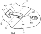
- the fall arrest device 100 also comprises a flexible link (502, Fig. 5 ) which has, at one of its ends, a first ring 504 intended to be fixed to the arm 404 in the fold of the second hooking strip 408 and, at the other of its ends, a second ring 506 provided for attach to the trim cover 50.
- a flexible link (502, Fig. 5 ) which has, at one of its ends, a first ring 504 intended to be fixed to the arm 404 in the fold of the second hooking strip 408 and, at the other of its ends, a second ring 506 provided for attach to the trim cover 50.
- the two attachment strips 406 and 408 are engaged and in the second position, the two attachment strips 406 and 408 are disjoint.
- the Fig. 5 shows the fall arrest device 100 in the first position.
- the first ring 504 is attached to the arm 404 because it is caught in the fold of the second strap 408 between the arm 404 and said second strap 408.
- the second ring 506 is attached to the trim cover 50 here by a fixing screw.
- the covering cap 50 When the covering cap 50 is pulled by a person present in the cockpit 12, the force is exerted substantially parallel to the junction surface and the two attachment strips 406 and 408 then separate to release the first ring 504.
- the first attachment band 406 does not extend to the free end of the arm 404 and the first ring 504 can then be position at the level of the zone devoid of first attachment band 406.
Landscapes
- Engineering & Computer Science (AREA)
- Mechanical Engineering (AREA)
- Aviation & Aerospace Engineering (AREA)
- Connection Of Plates (AREA)
- Aiming, Guidance, Guns With A Light Source, Armor, Camouflage, And Targets (AREA)
- Emergency Lowering Means (AREA)
- Helmets And Other Head Coverings (AREA)
Description
- La présente invention concerne un aéronef comportant une trappe structurelle associée à un capot d'habillage et au moins un dispositif antichute empêchant la chute du capot d'habillage, ainsi qu'un tel dispositif antichute.
- Actuellement, en cas d'incident, pour accéder à l'intérieur du cockpit d'un aéronef, lorsque la porte du cockpit ne peut pas être ouverte, il est prévu une trappe structurelle disposée en partie haute du cockpit. Cette trappe structurelle est associée à un capot d'habillage.
- L'aéronef comporte des moyens de verrouillage qui maintiennent le capot d'habillage en position fermée et fixé à la structure de l'aéronef et des moyens d'actionnement (par exemple, un bras fixé sur un côté de la trappe structurelle) associés à la trappe structurelle et qui exercent une pression sur les moyens de verrouillage. Lorsque la trappe structurelle doit être ouverte, les moyens de verrouillage sont déverrouillés depuis l'intérieur ou l'extérieur et le capot d'habillage n'est plus fixé à la structure de l'aéronef.
- Ainsi, lorsque la trappe structurelle passe en position ouverte, le capot d'habillage tombe à l'intérieur du cockpit au risque d'atteindre les personnes présentes dans le cockpit.
- Le document
EP0261329 décrit un dispositif d'ouverture de porte d'évacuation d'urgence depuis une cabine d'aéronef. Un tel dispositif comprend notamment deux organes expansibles permettant de contrôler l'ouverture et la rotation de la porte d'évacuation avant que celle-ci soit totalement séparée de l'aéronef. Le dispositif d'ouverture ainsi décrit n'est actionnable que depuis l'intérieur de la cabine d'aéronef et ne permet pas de réutiliser la porte d'évacuation. - Un objet de la présente invention est de proposer un aéronef comportant un dispositif antichute qui évite que le capot d'habillage libéré tombe sur les personnes présentes sous ledit capot d'habillage.
- A cet effet, est proposé un aéronef comportant :
- une structure présentant un toit percé d'une ouverture,
- un capot d'habillage, et
- des moyens de verrouillage prévus pour prendre alternativement une position de verrouillage dans laquelle ils maintiennent le capot d'habillage en position fermée dans l'ouverture, ou une position déverrouillée dans laquelle ils ne maintiennent pas le capot d'habillage, et
- au moins un dispositif antichute prévu pour, lorsque les moyens de verrouillage passent en position déverrouillée, être dans une première position dans laquelle il autorise le déplacement, sous l'effet de la pesanteur, du capot d'habillage de sa position fermée jusqu'à une position intermédiaire où le capot d'habillage est suspendu à la structure à l'intérieur de l'aéronef, et, puis pour passer de la première position à une deuxième position au cours de laquelle, le capot d'habillage passe de la position intermédiaire à une position dégagée dans laquelle il n'est plus lié à la structure.
- Un aéronef ainsi équipé d'un tel dispositif antichute permet d'arrêter la chute du capot d'habillage avant qu'il puisse être totalement retiré.
- Avantageusement, le passage de la première position à la deuxième position s'effectue sous l'action d'une force non colinéaire à la pesanteur.
- Avantageusement, la force extérieure est sensiblement perpendiculaire à la direction de la pesanteur. Chaque dispositif antichute comporte:
- un sabot fixé à la structure,
- un bras rigide présentant une première extrémité solidaire du sabot et s'étendant à partir du sabot selon une direction sensiblement perpendiculaire à la pesanteur,
- une première bande d'accrochage fixée sur une première face du bras rigide,
- une deuxième bande d'accrochage fixée sur une deuxième face du bras rigide opposée à la première face, la longueur de la deuxième bande d'accrochage est telle qu'elle peut par pliage autour d'une deuxième extrémité, appelée extrémité libre, du bras se replier sur la première bande d'accrochage pour s'y fixer de manière amovible le long d'une surface de jonction, et
- un lien souple comportant, à l'une de ses extrémités, un premier anneau prévu pour être fixé au bras dans le pli de la deuxième bande d'accrochage et, à l'autre de ses extrémités, un deuxième anneau prévu pour se fixer au capot d'habillage.
- Avantageusement, la première bande d'accrochage ne s'étend pas jusqu'à l'extrémité libre du bras et le premier anneau se positionne au niveau de la zone dépourvue de bande d'accrochage.
- Avantageusement, les moyens de fixation constituent un unique ensemble de fixation qui traverse le bras rigide.
- L'invention propose également un dispositif antichute prévu pour être mis en oeuvre dans un aéronef selon l'une des variantes précédentes.
- Les caractéristiques de l'invention mentionnées ci-dessus, ainsi que d'autres, apparaîtront plus clairement à la lecture de la description suivante d'un exemple de réalisation, ladite description étant faite en relation avec les dessins joints, parmi lesquels :
- la
Fig. 1 représente un aéronef selon l'invention, - la
Fig. 2 montre un capot d'habillage et des dispositifs antichute selon l'invention, - les
Figs. 3a-c montrent les différentes étapes de libération du capot d'habillage, - la
Fig. 4a est une vue d'un dispositif antichute, - la
Fig. 4b est une vue du dispositif antichute de laFig. 4a vue de l'autre côté, et - la
Fig. 5 est un agrandissement de laFig. 2 . - Dans la description qui suit, les termes relatifs à une position sont pris en référence à un aéronef en position normale de fonctionnement.
- La
Fig. 1 montre un aéronef 10 dont la structure présente un toit percé d'une ouverture (56,Fig. 2 ) au dessus d'un cockpit 12. L'aéronef 10 présente également une trappe structurelle (non représentée) et un capot d'habillage 50 qui obturent l'ouverture 56. Classiquement, la trappe structurelle est accessible directement depuis l'extérieur de l'aéronef 10 et permet d'atteindre le capot d'habillage 50 présent sur le toit du cockpit 12 afin de l'ouvrir et de pénétrer dans le cockpit 12. - Dans le reste de la description, le capot d'habillage 50 est disposé sur le toit du cockpit 12, et aligné sur la trappe structurelle (où que soit située cette dernière sur l'aéronef 10).
- La
Fig. 2 montre la face intérieure 52 du capot d'habillage 50, c'est-à-dire celle qui est tournée vers l'intérieur du cockpit 12, tandis que la face extérieure 54, c'est-à-dire celle qui est orientée vers l'extérieur de l'aéronef 10, a été partiellement retirée pour faciliter la compréhension de laFig. 2 . - Conformément au capot d'habillage de l'état de la technique, l'aéronef 10 comporte des moyens de verrouillage prévus pour prendre alternativement une position de verrouillage dans laquelle ils maintiennent le capot d'habillage 50 en position fermée dans l'ouverture 56, ou une position déverrouillée dans laquelle ils ne maintiennent pas le capot d'habillage 50 qui est alors libre de se déplacer.
- En position de verrouillage, les moyens de verrouillage qui ne sont pas représentés, verrouillent le capot d'habillage 50 sur la structure de l'aéronef 10.
- Lorsque les moyens de verrouillage sont déverrouillés, le capot d'habillage 50 se déplace sous son propre poids selon la direction de la pesanteur, c'est-à-dire ici sensiblement perpendiculaire au plan de l'ouverture 56 jusqu'à une position intermédiaire dans laquelle le capot d'habillage 50 est suspendu à la structure de l'aéronef 10 par des dispositifs antichute 100 (dont deux sont visibles sur la
Fig. 2 ). - Lorsque les moyens de verrouillage passent en position déverrouillée, chaque dispositif antichute 100 est dans une première position dans laquelle il autorise le déplacement, sous l'effet de la pesanteur, du capot d'habillage 50 de sa position fermée jusqu'à la position intermédiaire où le capot d'habillage 50 est suspendue à la structure de l'aéronef 10 par l'intermédiaire des dispositifs antichute 100. Dans cette position intermédiaire, le cockpit 12 est accessible depuis l'extérieur de l'aéronef 10.
- Puis chaque dispositif antichute 100 passe de la première position à une deuxième position au cours de laquelle le capot d'habillage 50 passe de la position intermédiaire à une position dégagée dans laquelle il n'est plus lié à la structure de l'aéronef 10.
- Le passage de la première position à la deuxième position s'effectue sous l'action d'une force non colinéaire à la pesanteur.
- Chaque dispositif antichute 100 limite ainsi le déplacement du capot d'habillage 50 selon la direction de la pesanteur jusqu'à la position intermédiaire où le capot d'habillage 50 est suspendu et donc évite sa chute dans le cockpit 12. Puis sous l'action d'une force extérieure, classiquement l'action d'une personne placée dans le cockpit 12, chaque dispositif antichute 100 passe dans la deuxième position où le capot d'habillage 50 est libéré et peut être dégagé de l'ouverture 56.
- De préférence, la force extérieure est sensiblement perpendiculaire à la direction de la pesanteur. Il s'agit par exemple d'une traction horizontale exercée par le personnel présent dans le cockpit 12 sur le capot d'habillage 50 suspendu en position intermédiaire. Ainsi, le personnel maintient le capot d'habillage 50 durant la dernière phase de libération et peut donc la diriger sans risque de chute de celle-ci.
- Les
Figs. 3a-c montrent les différentes étapes de libération du capot d'habillage 50. - Sur la
Fig. 3a , le capot d'habillage 50 est en position fermée et maintenue par les moyens de verrouillage. - Sur la
Fig. 3b , les moyens de verrouillage sont déverrouillés et le capot d'habillage 50 tombe en position intermédiaire sous l'effet de la pesanteur 30 et est maintenue dans cette position intermédiaire par les dispositifs antichute 100 qui sont en première position. - Sur la
Fig. 3c , la force extérieure 32 entraîne le passage de chaque dispositif antichute 100 en deuxième position et le capot d'habillage 50 passe alors en position dégagée par rupture de la liaison l'unissant à la structure de l'aéronef 10. - La longueur de suspension est de l'ordre de 10 cm.
- La
Fig. 4a et laFig. 4b montrent un dispositif antichute 100 qui comporte un sabot 402 prévu pour être fixé à la structure de l'aéronef 10, et un bras rigide 404. Le bras rigide 404 présente une première extrémité solidaire du sabot 402 et s'étend à partir du sabot 402 selon une direction sensiblement perpendiculaire à la pesanteur 30, c'est-à-dire ici sensiblement parallèlement au plan de l'ouverture 56. - Le dispositif antichute 100 comporte également une première bande d'accrochage 406 fixée sur une première face du bras rigide 404.
- Selon un mode de réalisation particulier, la bande d'accrochage 406 est collée sur le bras rigide 404. Selon un autre mode de réalisation particulier, la première bande d'accrochage 406 est fixée sur le bras rigide par des moyens de fixation 410, tels que des rivets ou des vis.
- Le dispositif antichute 100 comporte également une deuxième bande d'accrochage 408 fixée sur une deuxième face du bras rigide 404 opposée à la première face, et la longueur de la deuxième bande d'accrochage 408 est telle qu'elle peut par pliage autour d'une deuxième extrémité, appelée extrémité libre, du bras 404 se replier sur la première bande d'accrochage 406 pour s'y fixer le long d'une surface de jonction.
- Selon un mode de réalisation particulier, la deuxième bande d'accrochage 408 est collée sur le bras rigide. Selon un autre mode de réalisation particulier, la deuxième bande d'accrochage 408 est fixée sur le bras rigide par des moyens de fixation 412, tels que des rivets ou des vis.
- Afin que la fixation de la première bande d'accrochage 406 et la fixation de la deuxième bande d'accrochage 408 sur le bras rigide 404 se fassent de manière rapide, les moyens de fixation 410 et 412 constituent un unique ensemble de fixation qui traverse le bras rigide 404, et ainsi la fixation des bandes d'accrochage 406 et 408 s'effectue simultanément. L'ensemble de fixation ainsi défini est par exemple un système de rivet traversant le bras rigide 404 ou un système vis-écrou.
- Avantageusement, le dispositif antichute 100 est fixé sur la structure de l'aéronef 10 de sorte que la deuxième face du bras rigide 404 sur laquelle est fixée la deuxième bande d'accrochage 408 est orientée vers le plancher du cockpit 12 et que la première face du bras rigide 404 sur laquelle est fixée la première bande d'accrochage 406 est orientée du côté opposé au plancher.
- Les deux bandes d'accrochage 406 et 408 sont prévues pour s'accrocher l'une avec l'autre de manière amovible, c'est-à-dire qu'elles peuvent se séparer sous l'action d'une force extérieure.
- Les bandes d'accrochage 406 et 408 sont de préférence des bandes auto-agrippantes complémentaires, par exemple en velcro®.
- Le dispositif antichute 100 comporte également un lien souple (502,
Fig. 5 ) qui comporte, à l'une de ses extrémités, un premier anneau 504 prévu pour être fixé au bras 404 dans le pli de la deuxième bande d'accrochage 408 et, à l'autre de ses extrémités, un deuxième anneau 506 prévu pour se fixer au capot d'habillage 50. - Dans la première position, les deux bandes d'accrochage 406 et 408 sont en prises et dans la deuxième position, les deux bandes d'accrochage 406 et 408 sont disjointes.
- La
Fig. 5 montre le dispositif antichute 100 en première position. Le premier anneau 504 est fixé au bras 404 du fait qu'il est pris dans le pli de la deuxième bande d'accrochage 408 entre le bras 404 et ladite deuxième bande d'accrochage 408. - Le deuxième anneau 506 est fixé au capot d'habillage 50 ici par une vis de fixation.
- Lorsque le capot d'habillage 50 passe dans la position intermédiaire, le lien 502 se tend et le premier anneau 504 vient reposer sur l'extrémité libre du bras 404 qui supporte les efforts de pesanteur.
- Lorsque le capot d'habillage 50 est tiré par une personne présente dans le cockpit 12, la force s'exerce sensiblement parallèlement à la surface de jonction et les deux bandes d'accrochage 406 et 408 se séparent alors pour libérer le premier anneau 504.
- Pour permettre un bon positionnement du premier anneau 504 au niveau de l'extrémité libre du bras 404, la première bande d'accrochage 406 ne s'étend pas jusqu'à l'extrémité libre du bras 404 et le premier anneau 504 peut alors se positionner au niveau de la zone dépourvue de première bande d'accrochage 406.
Claims (3)
- Aéronef (10) comportant :- une structure présentant un toit percé d'une ouverture (56),- un capot d'habillage (50),- des moyens de verrouillage prévus pour prendre alternativement une position de verrouillage dans laquelle ils maintiennent le capot d'habillage (50) en position fermée dans l'ouverture (56), ou une position déverrouillée dans laquelle ils ne maintiennent pas le capot d'habillage (50), et- au moins un dispositif antichute (100) prévu pour, lorsque les moyens de verrouillage passent en position déverrouillée, être dans une première position dans laquelle il autorise le déplacement, sous l'effet de la pesanteur, du capot d'habillage (50) de sa position fermée jusqu'à une position intermédiaire où le capot d'habillage (50) est suspendu à la structure à l'intérieur de l'aéronef (10), et, puis pour passer de la première position à une deuxième position au cours de laquelle, le capot d'habillage (50) passe de la position intermédiaire à une position dégagée dans laquelle il n'est plus lié à la structure, l'aéronef étant caractérisé en ce que chaque dispositif anti-chute (100) comporte :- un sabot (402) fixé à la structure,- un bras rigide (404) présentant une première extrémité solidaire du sabot (402) et s'étendant à partir du sabot (402) selon une direction sensiblement perpendiculaire à la pesanteur (30),- une première bande d'accrochage (406) fixée sur une première face du bras rigide (404),- une deuxième bande d'accrochage (408) fixée sur une deuxième face du bras rigide (404) opposée à la première face, la longueur de la deuxième bande d'accrochage (408) est telle qu'elle peut par pliage autour d'une deuxième extrémité, appelée extrémité libre, du bras (404) se replier sur la première bande d'accrochage (406) pour s'y fixer de manière amovible le long d'une surface de jonction, et- un lien souple (502) comportant, à l'une de ses extrémités, un premier anneau (504) prévu pour être fixé au bras (404) dans le pli de la deuxième bande d'accrochage (408) et, à l'autre de ses extrémités, un deuxième anneau (506) prévu pour se fixer au capot d'habillage (50).
- Aéronef (10) selon la revendication 1, caractérisé en ce que la première bande d'accrochage (406) ne s'étend pas jusqu'à l'extrémité libre du bras (404) et en ce que le premier anneau (504) se positionne au niveau de la zone dépourvue de bande d'accrochage.
- Aéronef (10) selon la revendication 1, caractérisé en ce que les moyens de fixation (410, 412) constituent un unique ensemble de fixation qui traverse le bras rigide (404).
Applications Claiming Priority (1)
| Application Number | Priority Date | Filing Date | Title |
|---|---|---|---|
| FR1459218A FR3026385B1 (fr) | 2014-09-29 | 2014-09-29 | Aeronef comportant une trappe et un dispositif antichute |
Publications (2)
| Publication Number | Publication Date |
|---|---|
| EP3000721A1 EP3000721A1 (fr) | 2016-03-30 |
| EP3000721B1 true EP3000721B1 (fr) | 2018-07-25 |
Family
ID=51866259
Family Applications (1)
| Application Number | Title | Priority Date | Filing Date |
|---|---|---|---|
| EP15184221.8A Active EP3000721B1 (fr) | 2014-09-29 | 2015-09-08 | Aéronef comportant une trappe et un dispositif antichute |
Country Status (4)
| Country | Link |
|---|---|
| US (1) | US10377463B2 (fr) |
| EP (1) | EP3000721B1 (fr) |
| CN (1) | CN105460200B (fr) |
| FR (1) | FR3026385B1 (fr) |
Families Citing this family (2)
| Publication number | Priority date | Publication date | Assignee | Title |
|---|---|---|---|---|
| EP3501974B1 (fr) * | 2017-12-19 | 2020-02-05 | LEONARDO S.p.A. | Hélicoptère avec sortie de secours |
| JP7133489B2 (ja) * | 2019-01-29 | 2022-09-08 | フクビ化学工業株式会社 | 点検パネル用落下防止部材およびこれを含む点検口装置 |
Family Cites Families (28)
| Publication number | Priority date | Publication date | Assignee | Title |
|---|---|---|---|---|
| US1082909A (en) * | 1912-09-23 | 1913-12-30 | Oscar C Rixson | Door-stay. |
| US2199369A (en) * | 1939-06-29 | 1940-04-30 | Ottorino Bonomi | Door holder |
| US2453937A (en) * | 1947-04-23 | 1948-11-16 | Southwest Airways Company | Aircraft door |
| US2673760A (en) * | 1949-05-09 | 1954-03-30 | Otis J Hawks | Door holding device |
| US2754904A (en) * | 1953-04-13 | 1956-07-17 | Provenzano Gaetano | Safety door for aeroplanes |
| DE945975C (de) * | 1953-05-22 | 1956-07-19 | Morane Saulnier | Vorrichtung zum Verbinden von Flugzeugteilen |
| US2965336A (en) * | 1956-03-30 | 1960-12-20 | Lissarrague Pierre Jules | Device for forming an opening in a metallic panel |
| DE1064348B (de) * | 1956-03-30 | 1959-08-27 | Pierre Jules Lissarrague | Sicherheitsausgang in Flugzeugruempfen, Fahrzeugen od. dgl. |
| US3745709A (en) * | 1971-04-05 | 1973-07-17 | American Velcro Inc | Pull-out window frame |
| US3893725A (en) * | 1974-02-25 | 1975-07-08 | Glenn A Coulter | Device for latching containers |
| US4220298A (en) * | 1978-10-30 | 1980-09-02 | Willis Kathryn E | Removable soft door for aircraft |
| US4288119A (en) * | 1979-07-05 | 1981-09-08 | Air-Flo Co., Inc. | Door locking cable |
| US4312153A (en) * | 1979-12-14 | 1982-01-26 | Lockheed Corporation | Door seal |
| FR2547852A1 (fr) * | 1983-06-23 | 1984-12-28 | Rosa Fermeture Sa | Dispositif permettant de regler et de bloquer l'ouverture d'un volet battant d'une baie |
| DE3632122C1 (de) * | 1986-09-22 | 1987-11-12 | Airbus Gmbh | Notausgang an Fahrzeugen,insbesondere Luft- und Raumfahrzeugen |
| GB2236515A (en) * | 1989-08-24 | 1991-04-10 | Raam Shankar Pershadsingh | Civil passenger aircraft escape system |
| US5297692A (en) * | 1992-12-16 | 1994-03-29 | Kronmiller Leroy M | Cover retainer means |
| US6041960A (en) * | 1997-12-03 | 2000-03-28 | Leal; Richard J. | Connection assembly for preventing loss of garbage can cover |
| US7175213B1 (en) * | 2005-10-11 | 2007-02-13 | Robert Blangiardo | Handle rotation restraint and method |
| JP4834491B2 (ja) * | 2006-08-22 | 2011-12-14 | 株式会社東芝 | 転倒防止バンドおよび転倒防止バンドを有するディスプレイ装置 |
| DE102007051802B4 (de) * | 2007-10-30 | 2012-12-20 | Airbus Operations Gmbh | Aufenthaltsmodul mit einer Notausstiegsluke für ein Flugzeug |
| FR2950085B1 (fr) * | 2009-09-16 | 2011-12-16 | Saint Gobain Pont A Mousson | Attache de fixation pour un dispositif de voirie, ensemble, dispositif de voirie et procede correspondants |
| PT2441666E (pt) * | 2010-10-06 | 2013-08-27 | Agustawestland Spa | Uma montagem de porta, em particular para um helicóptero, provida de um dispositivo de desbloqueio de emergência |
| FR2973428B1 (fr) * | 2011-03-31 | 2019-03-15 | Airbus Helicopters | Encadrement etanche pour largage securise de panneau amovible |
| PL220639B1 (pl) * | 2011-10-06 | 2015-11-30 | Fakro Pp Spółka Z Ograniczoną Odpowiedzialnością | Schody składane, zwłaszcza czterosegmentowe |
| FR3032420B1 (fr) * | 2015-02-11 | 2017-01-13 | Airbus Operations Sas | Cabine de pilotage d'un avion equipee d'une evacuation de secours |
| US10023286B2 (en) * | 2015-11-19 | 2018-07-17 | The Boeing Company | Aircraft bay blankets that provide enhanced drainage features |
| EP3464060A1 (fr) * | 2016-05-31 | 2019-04-10 | Bombardier Inc. | Ensemble sortie de secours pour aéronef |
-
2014
- 2014-09-29 FR FR1459218A patent/FR3026385B1/fr active Active
-
2015
- 2015-08-28 US US14/838,383 patent/US10377463B2/en active Active
- 2015-09-08 EP EP15184221.8A patent/EP3000721B1/fr active Active
- 2015-09-24 CN CN201510617488.7A patent/CN105460200B/zh active Active
Non-Patent Citations (1)
| Title |
|---|
| None * |
Also Published As
| Publication number | Publication date |
|---|---|
| FR3026385A1 (fr) | 2016-04-01 |
| US20160185440A1 (en) | 2016-06-30 |
| FR3026385B1 (fr) | 2018-05-18 |
| US10377463B2 (en) | 2019-08-13 |
| CN105460200A (zh) | 2016-04-06 |
| EP3000721A1 (fr) | 2016-03-30 |
| CN105460200B (zh) | 2019-08-20 |
Similar Documents
| Publication | Publication Date | Title |
|---|---|---|
| EP3000721B1 (fr) | Aéronef comportant une trappe et un dispositif antichute | |
| CA2783706C (fr) | Mecanisme d'articulation frangible pour une cloison de plateforme, cloison, ensemble et procede associes | |
| EP3371047B1 (fr) | Porte de sortie d'urgence d'avion à mécanismes integrés et procédé d'ouverture/fermeture d'une telle porte | |
| FR2957333A1 (fr) | Equipement pour sauts en parachute destine a repartir les forces de tension d'un systeme ralentisseur, stabilisateur, extracteur | |
| CA2837712A1 (fr) | Avion et porte de cabine | |
| EP2658778B1 (fr) | Dispositif de solidarisation /désolidarisation et dispositif de largage associé | |
| EP2774848A1 (fr) | Système de fixation d'une charge à un giravion, et un giravion | |
| EP2402249B1 (fr) | Dispositif de sécurité pour parachute | |
| EP4098559B1 (fr) | Arrangement muni d'un système d'évacuation d'urgence | |
| EP2550183A1 (fr) | Volet de coussin de securite gonflable articule sur une planche de bord par un lien agence pour liberer une longueur supplementaire de lien sur ouverture de ce volet | |
| FR3046136A1 (fr) | Porte pour bord d'attaque d'une aile volante a bords lateraux paralleles au plan de symetrie. | |
| FR2508867A1 (fr) | ||
| FR2777537A1 (fr) | Structure de raccordement a cable separable d'un parachute | |
| FR3014383A1 (fr) | Dispositif de rangement, en particulier pour vehicule, planche de bord et vehicule correspondants | |
| FR2716084A1 (fr) | Dispositif de fermeture de combinaison vestimentaires. | |
| FR2942771A1 (fr) | Dispositif de deconnexion automatique d'un parachute secondaire en cas d'ouverture intempestive du conteneur principal | |
| CA3160725A1 (fr) | Porte d'aeronef a escamotage des moyens de retenue du dispositif d'evacuation deployable | |
| WO1988000154A1 (fr) | Dispositif pour la mise en oeuvre d'un parachute de secours | |
| EP0019574B1 (fr) | Dispositif de levage, en particulier moufle | |
| FR2935685A1 (fr) | Dispositif de deconnexion automatique d'un groupe d'elevateurs du parachute principal | |
| FR3015424A1 (fr) | Systeme de fixation d'une chaussure dans un bateau d'aviron | |
| FR2990172A1 (fr) | Amelioration du dispositif de deblocage rapide et aise de la ceinture de securite automobile, bloquee dans son systeme de verrouillage habituel | |
| FR3103086A1 (fr) | Système d’attache libérable pour jugulaires, verrou de mentonnière et casque de protection associés | |
| CH218256A (fr) | Equipement de parachute. | |
| FR2772339A1 (fr) | Dispositif de securite pour attacher une voilure de parachute a un harnais de parachutiste |
Legal Events
| Date | Code | Title | Description |
|---|---|---|---|
| PUAI | Public reference made under article 153(3) epc to a published international application that has entered the european phase |
Free format text: ORIGINAL CODE: 0009012 |
|
| AK | Designated contracting states |
Kind code of ref document: A1 Designated state(s): AL AT BE BG CH CY CZ DE DK EE ES FI FR GB GR HR HU IE IS IT LI LT LU LV MC MK MT NL NO PL PT RO RS SE SI SK SM TR |
|
| AX | Request for extension of the european patent |
Extension state: BA ME |
|
| 17P | Request for examination filed |
Effective date: 20160930 |
|
| RBV | Designated contracting states (corrected) |
Designated state(s): AL AT BE BG CH CY CZ DE DK EE ES FI FR GB GR HR HU IE IS IT LI LT LU LV MC MK MT NL NO PL PT RO RS SE SI SK SM TR |
|
| GRAP | Despatch of communication of intention to grant a patent |
Free format text: ORIGINAL CODE: EPIDOSNIGR1 |
|
| INTG | Intention to grant announced |
Effective date: 20180424 |
|
| GRAS | Grant fee paid |
Free format text: ORIGINAL CODE: EPIDOSNIGR3 |
|
| GRAA | (expected) grant |
Free format text: ORIGINAL CODE: 0009210 |
|
| AK | Designated contracting states |
Kind code of ref document: B1 Designated state(s): AL AT BE BG CH CY CZ DE DK EE ES FI FR GB GR HR HU IE IS IT LI LT LU LV MC MK MT NL NO PL PT RO RS SE SI SK SM TR |
|
| REG | Reference to a national code |
Ref country code: GB Ref legal event code: FG4D Free format text: NOT ENGLISH |
|
| REG | Reference to a national code |
Ref country code: CH Ref legal event code: EP |
|
| REG | Reference to a national code |
Ref country code: AT Ref legal event code: REF Ref document number: 1021464 Country of ref document: AT Kind code of ref document: T Effective date: 20180815 |
|
| REG | Reference to a national code |
Ref country code: IE Ref legal event code: FG4D Free format text: LANGUAGE OF EP DOCUMENT: FRENCH |
|
| REG | Reference to a national code |
Ref country code: DE Ref legal event code: R096 Ref document number: 602015013907 Country of ref document: DE |
|
| REG | Reference to a national code |
Ref country code: FR Ref legal event code: PLFP Year of fee payment: 4 |
|
| REG | Reference to a national code |
Ref country code: NL Ref legal event code: MP Effective date: 20180725 |
|
| REG | Reference to a national code |
Ref country code: LT Ref legal event code: MG4D |
|
| PG25 | Lapsed in a contracting state [announced via postgrant information from national office to epo] |
Ref country code: NL Free format text: LAPSE BECAUSE OF FAILURE TO SUBMIT A TRANSLATION OF THE DESCRIPTION OR TO PAY THE FEE WITHIN THE PRESCRIBED TIME-LIMIT Effective date: 20180725 |
|
| REG | Reference to a national code |
Ref country code: AT Ref legal event code: MK05 Ref document number: 1021464 Country of ref document: AT Kind code of ref document: T Effective date: 20180725 |
|
| PG25 | Lapsed in a contracting state [announced via postgrant information from national office to epo] |
Ref country code: NO Free format text: LAPSE BECAUSE OF FAILURE TO SUBMIT A TRANSLATION OF THE DESCRIPTION OR TO PAY THE FEE WITHIN THE PRESCRIBED TIME-LIMIT Effective date: 20181025 Ref country code: BG Free format text: LAPSE BECAUSE OF FAILURE TO SUBMIT A TRANSLATION OF THE DESCRIPTION OR TO PAY THE FEE WITHIN THE PRESCRIBED TIME-LIMIT Effective date: 20181025 Ref country code: GR Free format text: LAPSE BECAUSE OF FAILURE TO SUBMIT A TRANSLATION OF THE DESCRIPTION OR TO PAY THE FEE WITHIN THE PRESCRIBED TIME-LIMIT Effective date: 20181026 Ref country code: SE Free format text: LAPSE BECAUSE OF FAILURE TO SUBMIT A TRANSLATION OF THE DESCRIPTION OR TO PAY THE FEE WITHIN THE PRESCRIBED TIME-LIMIT Effective date: 20180725 Ref country code: RS Free format text: LAPSE BECAUSE OF FAILURE TO SUBMIT A TRANSLATION OF THE DESCRIPTION OR TO PAY THE FEE WITHIN THE PRESCRIBED TIME-LIMIT Effective date: 20180725 Ref country code: LT Free format text: LAPSE BECAUSE OF FAILURE TO SUBMIT A TRANSLATION OF THE DESCRIPTION OR TO PAY THE FEE WITHIN THE PRESCRIBED TIME-LIMIT Effective date: 20180725 Ref country code: PL Free format text: LAPSE BECAUSE OF FAILURE TO SUBMIT A TRANSLATION OF THE DESCRIPTION OR TO PAY THE FEE WITHIN THE PRESCRIBED TIME-LIMIT Effective date: 20180725 Ref country code: FI Free format text: LAPSE BECAUSE OF FAILURE TO SUBMIT A TRANSLATION OF THE DESCRIPTION OR TO PAY THE FEE WITHIN THE PRESCRIBED TIME-LIMIT Effective date: 20180725 Ref country code: IS Free format text: LAPSE BECAUSE OF FAILURE TO SUBMIT A TRANSLATION OF THE DESCRIPTION OR TO PAY THE FEE WITHIN THE PRESCRIBED TIME-LIMIT Effective date: 20181125 Ref country code: AT Free format text: LAPSE BECAUSE OF FAILURE TO SUBMIT A TRANSLATION OF THE DESCRIPTION OR TO PAY THE FEE WITHIN THE PRESCRIBED TIME-LIMIT Effective date: 20180725 |
|
| PG25 | Lapsed in a contracting state [announced via postgrant information from national office to epo] |
Ref country code: LV Free format text: LAPSE BECAUSE OF FAILURE TO SUBMIT A TRANSLATION OF THE DESCRIPTION OR TO PAY THE FEE WITHIN THE PRESCRIBED TIME-LIMIT Effective date: 20180725 Ref country code: HR Free format text: LAPSE BECAUSE OF FAILURE TO SUBMIT A TRANSLATION OF THE DESCRIPTION OR TO PAY THE FEE WITHIN THE PRESCRIBED TIME-LIMIT Effective date: 20180725 Ref country code: AL Free format text: LAPSE BECAUSE OF FAILURE TO SUBMIT A TRANSLATION OF THE DESCRIPTION OR TO PAY THE FEE WITHIN THE PRESCRIBED TIME-LIMIT Effective date: 20180725 |
|
| REG | Reference to a national code |
Ref country code: DE Ref legal event code: R097 Ref document number: 602015013907 Country of ref document: DE |
|
| PG25 | Lapsed in a contracting state [announced via postgrant information from national office to epo] |
Ref country code: CZ Free format text: LAPSE BECAUSE OF FAILURE TO SUBMIT A TRANSLATION OF THE DESCRIPTION OR TO PAY THE FEE WITHIN THE PRESCRIBED TIME-LIMIT Effective date: 20180725 Ref country code: IT Free format text: LAPSE BECAUSE OF FAILURE TO SUBMIT A TRANSLATION OF THE DESCRIPTION OR TO PAY THE FEE WITHIN THE PRESCRIBED TIME-LIMIT Effective date: 20180725 Ref country code: RO Free format text: LAPSE BECAUSE OF FAILURE TO SUBMIT A TRANSLATION OF THE DESCRIPTION OR TO PAY THE FEE WITHIN THE PRESCRIBED TIME-LIMIT Effective date: 20180725 Ref country code: EE Free format text: LAPSE BECAUSE OF FAILURE TO SUBMIT A TRANSLATION OF THE DESCRIPTION OR TO PAY THE FEE WITHIN THE PRESCRIBED TIME-LIMIT Effective date: 20180725 Ref country code: MC Free format text: LAPSE BECAUSE OF FAILURE TO SUBMIT A TRANSLATION OF THE DESCRIPTION OR TO PAY THE FEE WITHIN THE PRESCRIBED TIME-LIMIT Effective date: 20180725 Ref country code: ES Free format text: LAPSE BECAUSE OF FAILURE TO SUBMIT A TRANSLATION OF THE DESCRIPTION OR TO PAY THE FEE WITHIN THE PRESCRIBED TIME-LIMIT Effective date: 20180725 |
|
| REG | Reference to a national code |
Ref country code: CH Ref legal event code: PL |
|
| PG25 | Lapsed in a contracting state [announced via postgrant information from national office to epo] |
Ref country code: SK Free format text: LAPSE BECAUSE OF FAILURE TO SUBMIT A TRANSLATION OF THE DESCRIPTION OR TO PAY THE FEE WITHIN THE PRESCRIBED TIME-LIMIT Effective date: 20180725 Ref country code: DK Free format text: LAPSE BECAUSE OF FAILURE TO SUBMIT A TRANSLATION OF THE DESCRIPTION OR TO PAY THE FEE WITHIN THE PRESCRIBED TIME-LIMIT Effective date: 20180725 Ref country code: SM Free format text: LAPSE BECAUSE OF FAILURE TO SUBMIT A TRANSLATION OF THE DESCRIPTION OR TO PAY THE FEE WITHIN THE PRESCRIBED TIME-LIMIT Effective date: 20180725 |
|
| PLBE | No opposition filed within time limit |
Free format text: ORIGINAL CODE: 0009261 |
|
| STAA | Information on the status of an ep patent application or granted ep patent |
Free format text: STATUS: NO OPPOSITION FILED WITHIN TIME LIMIT |
|
| REG | Reference to a national code |
Ref country code: BE Ref legal event code: MM Effective date: 20180930 |
|
| REG | Reference to a national code |
Ref country code: IE Ref legal event code: MM4A |
|
| PG25 | Lapsed in a contracting state [announced via postgrant information from national office to epo] |
Ref country code: LU Free format text: LAPSE BECAUSE OF NON-PAYMENT OF DUE FEES Effective date: 20180908 |
|
| 26N | No opposition filed |
Effective date: 20190426 |
|
| PG25 | Lapsed in a contracting state [announced via postgrant information from national office to epo] |
Ref country code: IE Free format text: LAPSE BECAUSE OF NON-PAYMENT OF DUE FEES Effective date: 20180908 |
|
| PG25 | Lapsed in a contracting state [announced via postgrant information from national office to epo] |
Ref country code: LI Free format text: LAPSE BECAUSE OF NON-PAYMENT OF DUE FEES Effective date: 20180930 Ref country code: CH Free format text: LAPSE BECAUSE OF NON-PAYMENT OF DUE FEES Effective date: 20180930 Ref country code: BE Free format text: LAPSE BECAUSE OF NON-PAYMENT OF DUE FEES Effective date: 20180930 Ref country code: SI Free format text: LAPSE BECAUSE OF FAILURE TO SUBMIT A TRANSLATION OF THE DESCRIPTION OR TO PAY THE FEE WITHIN THE PRESCRIBED TIME-LIMIT Effective date: 20180725 |
|
| PG25 | Lapsed in a contracting state [announced via postgrant information from national office to epo] |
Ref country code: MT Free format text: LAPSE BECAUSE OF FAILURE TO SUBMIT A TRANSLATION OF THE DESCRIPTION OR TO PAY THE FEE WITHIN THE PRESCRIBED TIME-LIMIT Effective date: 20180725 |
|
| PG25 | Lapsed in a contracting state [announced via postgrant information from national office to epo] |
Ref country code: TR Free format text: LAPSE BECAUSE OF FAILURE TO SUBMIT A TRANSLATION OF THE DESCRIPTION OR TO PAY THE FEE WITHIN THE PRESCRIBED TIME-LIMIT Effective date: 20180725 |
|
| PG25 | Lapsed in a contracting state [announced via postgrant information from national office to epo] |
Ref country code: PT Free format text: LAPSE BECAUSE OF FAILURE TO SUBMIT A TRANSLATION OF THE DESCRIPTION OR TO PAY THE FEE WITHIN THE PRESCRIBED TIME-LIMIT Effective date: 20180725 |
|
| PG25 | Lapsed in a contracting state [announced via postgrant information from national office to epo] |
Ref country code: HU Free format text: LAPSE BECAUSE OF FAILURE TO SUBMIT A TRANSLATION OF THE DESCRIPTION OR TO PAY THE FEE WITHIN THE PRESCRIBED TIME-LIMIT; INVALID AB INITIO Effective date: 20150908 Ref country code: CY Free format text: LAPSE BECAUSE OF FAILURE TO SUBMIT A TRANSLATION OF THE DESCRIPTION OR TO PAY THE FEE WITHIN THE PRESCRIBED TIME-LIMIT Effective date: 20180725 Ref country code: MK Free format text: LAPSE BECAUSE OF NON-PAYMENT OF DUE FEES Effective date: 20180725 |
|
| PGFP | Annual fee paid to national office [announced via postgrant information from national office to epo] |
Ref country code: GB Payment date: 20230920 Year of fee payment: 9 |
|
| PGFP | Annual fee paid to national office [announced via postgrant information from national office to epo] |
Ref country code: FR Payment date: 20230928 Year of fee payment: 9 Ref country code: DE Payment date: 20230920 Year of fee payment: 9 |