EP3000583A1 - Fahrzeugkomponente mit Hitzeschild und Verfahren zur Herstellung davon - Google Patents
Fahrzeugkomponente mit Hitzeschild und Verfahren zur Herstellung davon Download PDFInfo
- Publication number
- EP3000583A1 EP3000583A1 EP14186920.6A EP14186920A EP3000583A1 EP 3000583 A1 EP3000583 A1 EP 3000583A1 EP 14186920 A EP14186920 A EP 14186920A EP 3000583 A1 EP3000583 A1 EP 3000583A1
- Authority
- EP
- European Patent Office
- Prior art keywords
- vehicle component
- heat
- layer
- reinforcement layer
- thermoplastic material
- Prior art date
- Legal status (The legal status is an assumption and is not a legal conclusion. Google has not performed a legal analysis and makes no representation as to the accuracy of the status listed.)
- Withdrawn
Links
Images


Classifications
-
- B—PERFORMING OPERATIONS; TRANSPORTING
- B29—WORKING OF PLASTICS; WORKING OF SUBSTANCES IN A PLASTIC STATE IN GENERAL
- B29C—SHAPING OR JOINING OF PLASTICS; SHAPING OF MATERIAL IN A PLASTIC STATE, NOT OTHERWISE PROVIDED FOR; AFTER-TREATMENT OF THE SHAPED PRODUCTS, e.g. REPAIRING
- B29C49/00—Blow-moulding, i.e. blowing a preform or parison to a desired shape within a mould; Apparatus therefor
- B29C49/02—Combined blow-moulding and manufacture of the preform or the parison
- B29C49/04—Extrusion blow-moulding
-
- B—PERFORMING OPERATIONS; TRANSPORTING
- B29—WORKING OF PLASTICS; WORKING OF SUBSTANCES IN A PLASTIC STATE IN GENERAL
- B29C—SHAPING OR JOINING OF PLASTICS; SHAPING OF MATERIAL IN A PLASTIC STATE, NOT OTHERWISE PROVIDED FOR; AFTER-TREATMENT OF THE SHAPED PRODUCTS, e.g. REPAIRING
- B29C49/00—Blow-moulding, i.e. blowing a preform or parison to a desired shape within a mould; Apparatus therefor
- B29C49/20—Blow-moulding, i.e. blowing a preform or parison to a desired shape within a mould; Apparatus therefor of articles having inserts or reinforcements ; Handling of inserts or reinforcements
-
- B—PERFORMING OPERATIONS; TRANSPORTING
- B60—VEHICLES IN GENERAL
- B60K—ARRANGEMENT OR MOUNTING OF PROPULSION UNITS OR OF TRANSMISSIONS IN VEHICLES; ARRANGEMENT OR MOUNTING OF PLURAL DIVERSE PRIME-MOVERS IN VEHICLES; AUXILIARY DRIVES FOR VEHICLES; INSTRUMENTATION OR DASHBOARDS FOR VEHICLES; ARRANGEMENTS IN CONNECTION WITH COOLING, AIR INTAKE, GAS EXHAUST OR FUEL SUPPLY OF PROPULSION UNITS IN VEHICLES
- B60K15/00—Arrangement in connection with fuel supply of combustion engines or other fuel consuming energy converters, e.g. fuel cells; Mounting or construction of fuel tanks
- B60K15/03—Fuel tanks
- B60K15/03177—Fuel tanks made of non-metallic material, e.g. plastics, or of a combination of non-metallic and metallic material
-
- B—PERFORMING OPERATIONS; TRANSPORTING
- B29—WORKING OF PLASTICS; WORKING OF SUBSTANCES IN A PLASTIC STATE IN GENERAL
- B29C—SHAPING OR JOINING OF PLASTICS; SHAPING OF MATERIAL IN A PLASTIC STATE, NOT OTHERWISE PROVIDED FOR; AFTER-TREATMENT OF THE SHAPED PRODUCTS, e.g. REPAIRING
- B29C49/00—Blow-moulding, i.e. blowing a preform or parison to a desired shape within a mould; Apparatus therefor
- B29C49/20—Blow-moulding, i.e. blowing a preform or parison to a desired shape within a mould; Apparatus therefor of articles having inserts or reinforcements ; Handling of inserts or reinforcements
- B29C2049/2017—Blow-moulding, i.e. blowing a preform or parison to a desired shape within a mould; Apparatus therefor of articles having inserts or reinforcements ; Handling of inserts or reinforcements outside the article
-
- B—PERFORMING OPERATIONS; TRANSPORTING
- B29—WORKING OF PLASTICS; WORKING OF SUBSTANCES IN A PLASTIC STATE IN GENERAL
- B29C—SHAPING OR JOINING OF PLASTICS; SHAPING OF MATERIAL IN A PLASTIC STATE, NOT OTHERWISE PROVIDED FOR; AFTER-TREATMENT OF THE SHAPED PRODUCTS, e.g. REPAIRING
- B29C49/00—Blow-moulding, i.e. blowing a preform or parison to a desired shape within a mould; Apparatus therefor
- B29C49/20—Blow-moulding, i.e. blowing a preform or parison to a desired shape within a mould; Apparatus therefor of articles having inserts or reinforcements ; Handling of inserts or reinforcements
- B29C2049/2021—Inserts characterised by the material or type
- B29C2049/2065—Inserts characterised by the material or type for reinforcing specific areas of the final blow moulded article
-
- B—PERFORMING OPERATIONS; TRANSPORTING
- B29—WORKING OF PLASTICS; WORKING OF SUBSTANCES IN A PLASTIC STATE IN GENERAL
- B29C—SHAPING OR JOINING OF PLASTICS; SHAPING OF MATERIAL IN A PLASTIC STATE, NOT OTHERWISE PROVIDED FOR; AFTER-TREATMENT OF THE SHAPED PRODUCTS, e.g. REPAIRING
- B29C49/00—Blow-moulding, i.e. blowing a preform or parison to a desired shape within a mould; Apparatus therefor
- B29C49/20—Blow-moulding, i.e. blowing a preform or parison to a desired shape within a mould; Apparatus therefor of articles having inserts or reinforcements ; Handling of inserts or reinforcements
- B29C2049/2086—Means for verifying or keeping the position of the insert, e.g. sensors, or attachment on mould wall
-
- B—PERFORMING OPERATIONS; TRANSPORTING
- B29—WORKING OF PLASTICS; WORKING OF SUBSTANCES IN A PLASTIC STATE IN GENERAL
- B29C—SHAPING OR JOINING OF PLASTICS; SHAPING OF MATERIAL IN A PLASTIC STATE, NOT OTHERWISE PROVIDED FOR; AFTER-TREATMENT OF THE SHAPED PRODUCTS, e.g. REPAIRING
- B29C49/00—Blow-moulding, i.e. blowing a preform or parison to a desired shape within a mould; Apparatus therefor
- B29C49/20—Blow-moulding, i.e. blowing a preform or parison to a desired shape within a mould; Apparatus therefor of articles having inserts or reinforcements ; Handling of inserts or reinforcements
- B29C2049/2095—Means for preparing or treating the inserts, e.g. cutting, deforming, heating, cooling or applying adhesives
-
- B—PERFORMING OPERATIONS; TRANSPORTING
- B29—WORKING OF PLASTICS; WORKING OF SUBSTANCES IN A PLASTIC STATE IN GENERAL
- B29K—INDEXING SCHEME ASSOCIATED WITH SUBCLASSES B29B, B29C OR B29D, RELATING TO MOULDING MATERIALS OR TO MATERIALS FOR MOULDS, REINFORCEMENTS, FILLERS OR PREFORMED PARTS, e.g. INSERTS
- B29K2995/00—Properties of moulding materials, reinforcements, fillers, preformed parts or moulds
- B29K2995/0012—Properties of moulding materials, reinforcements, fillers, preformed parts or moulds having particular thermal properties
- B29K2995/0015—Insulating
-
- B—PERFORMING OPERATIONS; TRANSPORTING
- B29—WORKING OF PLASTICS; WORKING OF SUBSTANCES IN A PLASTIC STATE IN GENERAL
- B29K—INDEXING SCHEME ASSOCIATED WITH SUBCLASSES B29B, B29C OR B29D, RELATING TO MOULDING MATERIALS OR TO MATERIALS FOR MOULDS, REINFORCEMENTS, FILLERS OR PREFORMED PARTS, e.g. INSERTS
- B29K2995/00—Properties of moulding materials, reinforcements, fillers, preformed parts or moulds
- B29K2995/0037—Other properties
- B29K2995/0077—Yield strength; Tensile strength
-
- B—PERFORMING OPERATIONS; TRANSPORTING
- B29—WORKING OF PLASTICS; WORKING OF SUBSTANCES IN A PLASTIC STATE IN GENERAL
- B29L—INDEXING SCHEME ASSOCIATED WITH SUBCLASS B29C, RELATING TO PARTICULAR ARTICLES
- B29L2031/00—Other particular articles
- B29L2031/712—Containers; Packaging elements or accessories, Packages
- B29L2031/7172—Fuel tanks, jerry cans
-
- B—PERFORMING OPERATIONS; TRANSPORTING
- B32—LAYERED PRODUCTS
- B32B—LAYERED PRODUCTS, i.e. PRODUCTS BUILT-UP OF STRATA OF FLAT OR NON-FLAT, e.g. CELLULAR OR HONEYCOMB, FORM
- B32B15/00—Layered products comprising a layer of metal
- B32B15/14—Layered products comprising a layer of metal next to a fibrous or filamentary layer
-
- B—PERFORMING OPERATIONS; TRANSPORTING
- B32—LAYERED PRODUCTS
- B32B—LAYERED PRODUCTS, i.e. PRODUCTS BUILT-UP OF STRATA OF FLAT OR NON-FLAT, e.g. CELLULAR OR HONEYCOMB, FORM
- B32B15/00—Layered products comprising a layer of metal
- B32B15/20—Layered products comprising a layer of metal comprising aluminium or copper
-
- B—PERFORMING OPERATIONS; TRANSPORTING
- B32—LAYERED PRODUCTS
- B32B—LAYERED PRODUCTS, i.e. PRODUCTS BUILT-UP OF STRATA OF FLAT OR NON-FLAT, e.g. CELLULAR OR HONEYCOMB, FORM
- B32B2307/00—Properties of the layers or laminate
- B32B2307/30—Properties of the layers or laminate having particular thermal properties
- B32B2307/304—Insulating
-
- B—PERFORMING OPERATIONS; TRANSPORTING
- B32—LAYERED PRODUCTS
- B32B—LAYERED PRODUCTS, i.e. PRODUCTS BUILT-UP OF STRATA OF FLAT OR NON-FLAT, e.g. CELLULAR OR HONEYCOMB, FORM
- B32B2307/00—Properties of the layers or laminate
- B32B2307/50—Properties of the layers or laminate having particular mechanical properties
- B32B2307/54—Yield strength; Tensile strength
-
- B—PERFORMING OPERATIONS; TRANSPORTING
- B32—LAYERED PRODUCTS
- B32B—LAYERED PRODUCTS, i.e. PRODUCTS BUILT-UP OF STRATA OF FLAT OR NON-FLAT, e.g. CELLULAR OR HONEYCOMB, FORM
- B32B2605/00—Vehicles
-
- B—PERFORMING OPERATIONS; TRANSPORTING
- B32—LAYERED PRODUCTS
- B32B—LAYERED PRODUCTS, i.e. PRODUCTS BUILT-UP OF STRATA OF FLAT OR NON-FLAT, e.g. CELLULAR OR HONEYCOMB, FORM
- B32B27/00—Layered products comprising a layer of synthetic resin
- B32B27/06—Layered products comprising a layer of synthetic resin as the main or only constituent of a layer, which is next to another layer of the same or of a different material
- B32B27/065—Layered products comprising a layer of synthetic resin as the main or only constituent of a layer, which is next to another layer of the same or of a different material of foam
-
- B—PERFORMING OPERATIONS; TRANSPORTING
- B32—LAYERED PRODUCTS
- B32B—LAYERED PRODUCTS, i.e. PRODUCTS BUILT-UP OF STRATA OF FLAT OR NON-FLAT, e.g. CELLULAR OR HONEYCOMB, FORM
- B32B27/00—Layered products comprising a layer of synthetic resin
- B32B27/32—Layered products comprising a layer of synthetic resin comprising polyolefins
-
- B—PERFORMING OPERATIONS; TRANSPORTING
- B32—LAYERED PRODUCTS
- B32B—LAYERED PRODUCTS, i.e. PRODUCTS BUILT-UP OF STRATA OF FLAT OR NON-FLAT, e.g. CELLULAR OR HONEYCOMB, FORM
- B32B5/00—Layered products characterised by the non- homogeneity or physical structure, i.e. comprising a fibrous, filamentary, particulate or foam layer; Layered products characterised by having a layer differing constitutionally or physically in different parts
- B32B5/02—Layered products characterised by the non- homogeneity or physical structure, i.e. comprising a fibrous, filamentary, particulate or foam layer; Layered products characterised by having a layer differing constitutionally or physically in different parts characterised by structural features of a fibrous or filamentary layer
-
- B—PERFORMING OPERATIONS; TRANSPORTING
- B32—LAYERED PRODUCTS
- B32B—LAYERED PRODUCTS, i.e. PRODUCTS BUILT-UP OF STRATA OF FLAT OR NON-FLAT, e.g. CELLULAR OR HONEYCOMB, FORM
- B32B5/00—Layered products characterised by the non- homogeneity or physical structure, i.e. comprising a fibrous, filamentary, particulate or foam layer; Layered products characterised by having a layer differing constitutionally or physically in different parts
- B32B5/18—Layered products characterised by the non- homogeneity or physical structure, i.e. comprising a fibrous, filamentary, particulate or foam layer; Layered products characterised by having a layer differing constitutionally or physically in different parts characterised by features of a layer of foamed material
-
- B—PERFORMING OPERATIONS; TRANSPORTING
- B32—LAYERED PRODUCTS
- B32B—LAYERED PRODUCTS, i.e. PRODUCTS BUILT-UP OF STRATA OF FLAT OR NON-FLAT, e.g. CELLULAR OR HONEYCOMB, FORM
- B32B7/00—Layered products characterised by the relation between layers; Layered products characterised by the relative orientation of features between layers, or by the relative values of a measurable parameter between layers, i.e. products comprising layers having different physical, chemical or physicochemical properties; Layered products characterised by the interconnection of layers
- B32B7/04—Interconnection of layers
- B32B7/12—Interconnection of layers using interposed adhesives or interposed materials with bonding properties
-
- B—PERFORMING OPERATIONS; TRANSPORTING
- B60—VEHICLES IN GENERAL
- B60K—ARRANGEMENT OR MOUNTING OF PROPULSION UNITS OR OF TRANSMISSIONS IN VEHICLES; ARRANGEMENT OR MOUNTING OF PLURAL DIVERSE PRIME-MOVERS IN VEHICLES; AUXILIARY DRIVES FOR VEHICLES; INSTRUMENTATION OR DASHBOARDS FOR VEHICLES; ARRANGEMENTS IN CONNECTION WITH COOLING, AIR INTAKE, GAS EXHAUST OR FUEL SUPPLY OF PROPULSION UNITS IN VEHICLES
- B60K15/00—Arrangement in connection with fuel supply of combustion engines or other fuel consuming energy converters, e.g. fuel cells; Mounting or construction of fuel tanks
- B60K15/03—Fuel tanks
- B60K2015/03032—Manufacturing of fuel tanks
- B60K2015/03039—Manufacturing of fuel tanks made of a combination of non metallic and metallic materials
-
- B—PERFORMING OPERATIONS; TRANSPORTING
- B60—VEHICLES IN GENERAL
- B60K—ARRANGEMENT OR MOUNTING OF PROPULSION UNITS OR OF TRANSMISSIONS IN VEHICLES; ARRANGEMENT OR MOUNTING OF PLURAL DIVERSE PRIME-MOVERS IN VEHICLES; AUXILIARY DRIVES FOR VEHICLES; INSTRUMENTATION OR DASHBOARDS FOR VEHICLES; ARRANGEMENTS IN CONNECTION WITH COOLING, AIR INTAKE, GAS EXHAUST OR FUEL SUPPLY OF PROPULSION UNITS IN VEHICLES
- B60K15/00—Arrangement in connection with fuel supply of combustion engines or other fuel consuming energy converters, e.g. fuel cells; Mounting or construction of fuel tanks
- B60K15/03—Fuel tanks
- B60K2015/03032—Manufacturing of fuel tanks
- B60K2015/03046—Manufacturing of fuel tanks made from more than one layer
-
- B—PERFORMING OPERATIONS; TRANSPORTING
- B60—VEHICLES IN GENERAL
- B60K—ARRANGEMENT OR MOUNTING OF PROPULSION UNITS OR OF TRANSMISSIONS IN VEHICLES; ARRANGEMENT OR MOUNTING OF PLURAL DIVERSE PRIME-MOVERS IN VEHICLES; AUXILIARY DRIVES FOR VEHICLES; INSTRUMENTATION OR DASHBOARDS FOR VEHICLES; ARRANGEMENTS IN CONNECTION WITH COOLING, AIR INTAKE, GAS EXHAUST OR FUEL SUPPLY OF PROPULSION UNITS IN VEHICLES
- B60K15/00—Arrangement in connection with fuel supply of combustion engines or other fuel consuming energy converters, e.g. fuel cells; Mounting or construction of fuel tanks
- B60K15/03—Fuel tanks
- B60K2015/03328—Arrangements or special measures related to fuel tanks or fuel handling
- B60K2015/03421—Arrangements or special measures related to fuel tanks or fuel handling to protect the fuel tank against heat
Definitions
- the invention relates to a vehicle component made from a thermoplastic material, in particular a vehicle tank or a filler pipe, said vehicle component being provided with a heat shield.
- the invention also relates to a method for manufacturing such a vehicle component.
- a prior art vehicle component may be provided with a heat shield for blocking and/or reducing the transfer of heat to the vehicle component.
- a heat shield for blocking and/or reducing the transfer of heat to the vehicle component.
- heat shields in metal, which are fixed on or near the wall of a vehicle tank using e.g. clips or adhesive. Such heat shields are used to reduce the amount of heat that is transferred to the vehicle tank, e.g. heat from a hot element such as an exhaust pipe, which is arranged near the vehicle tank.
- Such metal shields are dangerous to handle in view of the risk on cuts when manipulating such heat shields. Further, when a heat shield is fixed using clips, noise may occur due to vibrations of the heat shield. Also, adhesive heat shields may peel off after aging.
- the object of embodiments of the invention is to provide an improved vehicle component on which a heat shield is arranged in an improved manner.
- a further object is to provide an improved method for manufacturing such a vehicle component.
- a vehicle component made from a thermoplastic material, in particular a vehicle tank or a filler pipe, said vehicle component having a wall, wherein a heat shield is adhered to the wall.
- the heat shield comprises a reinforcement layer made from a thermoplastic material which is weldable to the thermoplastic material of the vehicle component; said reinforcement layer being welded to said wall; and a heat shielding material which differs from said thermoplastic material of said reinforcement layer and which is configured for decreasing the transfer of heat through the reinforcement layer to the vehicle component.
- a heat shield is obtained that is integrated with the vehicle component. In that way handling of the vehicle component with heat shield is easier, and vibration noises or peel-off due to aging can be avoided.
- the term "welded" refers to the fact that the material of the reinforcement layer is adhered to the wall of the tank in a molten state thereof so that a continuous and reliable bond is achieved. Further, by combining the reinforcement and heat shielding function, also deformations of the vehicle component at a critical location, namely close to a hot element, can be significantly reduced.
- the reinforcement layer is a fiber filled reinforcement layer, and in particular a pre-impregnated fiber composite (prepreg) layer.
- the reinforcement layer may comprise a thermoplastic material and fibers.
- the fibers may be cut fibers, or woven or non-woven long or continuous fibers.
- the fibers are included in the form of a woven mat of fibers, more preferably a woven mat of glass fibers.
- carbon fibers, natural fibers or polymer fibers, e.g. polyamide fibers may also be used.
- the thermoplastic material is configured to be weldable to the material of the tank, and may be a polyolefin material, in particular a polyethylene material, and e.g.
- the surface of the fibers may be treated with a compatibilist substance such as silane and/or a reactive binder, e.g. the HDPE reactive type.
- a compatibilist substance such as silane and/or a reactive binder, e.g. the HDPE reactive type.
- the thermoplastic material content in the thermoplastic material is lower than 50 percent, more preferably lower than 30 %.
- the fiber content is higher than 50 percent, more preferably higher than 70 percent. More details about suitable reinforcement layers can be found in patent application FR2 957 296-A1 in the name of the Applicant, which is included herein by reference.
- the reinforcement layer has a thickness between 0,1 and 2,5 mm, more preferably between 0,5 and 1,5 mm.
- the reinforcement layer has a tensile modulus, measured in accordance with the ASTM D638 test method, higher than 3000 MPa.
- the heat shielding material comprises a heat-insulating layer of a heat insulation material, said heat-insulating layer being provided against the reinforcement layer.
- a heat-insulating layer will reduce the heat that is transferred to the vehicle component.
- the heat insulation material is a foam material, e.g. polyurethane foam. Such a foam material may be glued against the reinforcement layer (with cyanoacrylate glue for instance).
- the heat insulation material has a thermal conductivity (K-value), which is lower than 0,06 W/mK, more preferably lower than 0,04 W/mK.
- the thermal conductivity of polyethylene is about 0.44 W/mK
- the thermal conductivity of polyamide 6 is about 0.29 W/mK
- the thermal conductivity of polyurethane foam is about 0.03W/mK.
- the heat-insulation material has a tensile modulus, measured in accordance with the ASTM D638 test method, which is higher than 900 MPa.
- the heat-insulating layer may further contribute to the stiffness and may reduce the tendency of the vehicle component to deform.
- the heat-insulating layer has a thickness between 1 and 10 mm, more preferably between 3 and 7 mm.
- the heat shielding material comprises a reflective layer that forms the outer layer of the heat shield, said reflective layer being configured for reflecting heat radiation. By reflecting heat radiation, less heat is transferred to the vehicle component.
- the reflective layer is a metal layer.
- the reflective layer is a thin aluminium sheet with a thickness which is lower than 0,5 mm.
- the reflective layer may be adhered to the heat-insulating layer.
- the reflective layer may be adhered to the reinforcement layer.
- the heat shielding material comprises metal particles arranged at least in an outer layer of the heat shield, such that heat is reflected at said outer layer.
- metal particles may be included in the reinforcement layer or in a separate layer on top of the reinforcement layer or on top on the heat-insulating layer, if present.
- a thermally reflecting coating could be applied as well.
- the vehicle component may be a tank.
- the tank may be a fuel tank or an additive tank for a vehicle.
- the tank may comprise a first shell and a second shell, wherein edges of said first and second shell are mutually connected such that said first and second shell together form a container delimiting an internal volume.
- the reinforcement layer may be welded, e.g. by overmoulding, either to the first or the second shell.
- the tank is made of a thermoplastic material.
- thermoplastic material is understood to mean any thermoplastic polymer, including thermoplastic elastomers, and blends thereof.
- polymer is understood to mean both homopolymers and copolymers (especially binary or ternary copolymers).
- copolymers examples include random copolymers, linear block copolymers, other block copolymers and graft copolymers.
- One polymer often employed is high-density polyethylene (HDPE).
- HDPE high-density polyethylene
- excellent results may also be obtained with other polyolefins, with polyamides, with thermoplastic polyesters, with polyketones, and with copolymers thereof.
- a blend of different polymers or copolymers, optionally mixed with additives, may be used.
- the tank may be a single layer tank or a multilayer tank comprising one or more barrier layers.
- the term "fuel tank” is understood to mean a substantially impermeable tank that can store fuel under diverse and varied environmental and usage conditions.
- a fuel tank also comprises a layer of a fuel-impermeable resin such as, for example, EVOH (a partially hydrolysed ethylene/vinyl acetate copolymer).
- EVOH a partially hydrolysed ethylene/vinyl acetate copolymer
- the tank may be subjected to a surface treatment (fluorination or sulphonation) for the purpose of making it impermeable to fuel.
- a multilayer fuel tank comprising an EVOH layer between two HDPE layers is successfully used in the context of the invention.
- additive tank is understood to mean a substantially impermeable tank that can store additive under diverse and varied environmental and usage conditions.
- the additive is typically an ammonia precursor solution.
- the vehicle component may be a filler pipe.
- the reinforcement layer may then be welded to the outer wall of the filler pipe.
- the filler pipe is pipe used for filling a tank with fluid.
- filler pipes typically have a diameter between 20 and 60 mm, more preferably between 25 and 50 mm, and a length that is more than 15 cm.
- a method for manufacturing a vehicle component made from a thermoplastic material comprises adhering a heat shield to a wall of the vehicle component.
- the heat shield comprising a reinforcement layer made from a thermoplastic material that is weldable to the thermoplastic material of the vehicle component, and a heat shielding material which differs from said thermoplastic material of said layer and which is configured for decreasing the transfer of heat through the reinforcement layer to the vehicle component.
- the adhering comprises welding the reinforcement layer to the wall.
- welding refers to the fact that the thermoplastic material of the vehicle component and the thermoplastic material of the reinforcement layer are in a molten state when they are adhered to each other.
- the application of pressure which is often used throughout both the heating and cooling stages, is used to keep the parts in the proper orientation and to improve melt flow across the welding interface.
- the compression of melt layers encourages polymer chains entanglement between the two parts.
- the purpose of the heating stage is to allow intermolecular entanglement from one part to the other across the faying surface (melt mixing).
- the adhering comprises placing the heat shield in a mold; and blow-molding the vehicle component in said mold such that the reinforcement layer is welded to the thermoplastic material of the vehicle component.
- the mold after the blow-molding, the mold is kept at a predetermined temperature during a predetermined time period for obtaining a good adherence of the reinforcement layer to the wall of the blow-molded vehicle component.
- the heat shield before placing the heat shield in the mold, the heat shield is heated to bring the thermoplastic material of the reinforcement layer in a molten state. Also, the heat shield may be preformed before positioning the heat shield in the mold.
- the adhering comprises welding the heat shield to a wall of a vehicle component.
- the reinforcement layer may be formed by melting the thermoplastic material around/in a fiber mass, e.g. a woven fiber mat, so that a reinforcement layer is obtained having at least one surface that is weldable to the vehicle component.
- the reinforcement layer may be manufactured by calendaring, compression moulding, injection moulding, etc.
- the heat shielding material comprises a heat-insulating layer of a heat insulation material, said heat-insulating layer being arranged against the reinforcement layer.
- the heat insulation material is a foam material.
- the heat-insulating layer may be arranged against the reinforcement layer using suitable glue.
- the heat shielding material may comprise a reflective layer, e.g. a metal layer, which forms an outer layer of the heat shield, said reflective layer being configured for reflecting heat radiation.
- a reflective layer may be glued against the reinforcement layer or against the heat-insulating layer, if the latter is present.
- the reflective layer may be laminated together with the reinforcement layer or may be integrated on the reinforcement layer during the manufacturing process thereof, e.g. using a pulltrusion process.
- the reflective layer is a thin aluminium sheet with a thickness which is lower than 0,5 mm
- polyethylene grafter with maleic anhydride might be used to improve the bonding with insulation material.
- FIGs 1 and 2 illustrate a first embodiment of a vehicle tank 10, here a saddle tank, made from a thermoplastic material, e.g. HDPE, wherein a heat shield 20 is adhered to an outer wall of the tank 10, and in particular to a wall part of the recess in the bottom of the tank 10.
- the heat shield 20 comprises a reinforcement layer 21, a heat-insulating layer 22 and a reflective layer 23.
- the reinforcement layer 21 is made from a thermoplastic material, e.g. HDPE, which is weldable to the thermoplastic material of the vehicle tank.
- the reinforcement layer 21 is welded to the outer wall 10.
- the heat shielding material consists of the heat-insulting layer 22 and the reflective layer 23. These layers 22, 23 are configured for decreasing the transfer of heat through the reinforcement layer 21 to the vehicle tank.
- the reinforcement layer 21 is a fiber filled reinforcement layer, and more in particular a pre-impregnated fibers composite layer, i.e. a so-called prepreg layer.
- the reinforcement layer 21 may comprise a thermoplastic material and fibers.
- the fibers may be cut fibers, or woven or non-woven long or continuous fibers.
- the fibers are included in the form of a woven mat of fibers, more preferably a woven mat of glass fibers.
- the reinforcement layer 21 has a thickness t2 between 0,1 and 2,5 mm, more preferably between 0,5 and 1,5 mm.
- the wall of the tank 10 has a thickness t1 between 2 and 10 mm, preferably between 3 and 8 mm.
- the heat-insulating layer 22 is arranged against the reinforcement layer 21. Such a heat-insulating layer 22 will reduce the heat that is transferred to the tank 10.
- the heat-insulating layer 22 is made of a foam material, e.g. polyurethane foam. Such a foam material may be glued against the reinforcement layer 21.
- the foam material has a thermal conductivity (K-value), which is lower than 0,06 W/mK, more preferably lower than 0,04 W/mK.
- K-value thermal conductivity
- the heat-insulating layer 22 has a thickness t3 between 1 and 10 mm, more preferably between 3 and 7 mm
- the reflective layer 23 forms the outer layer of the heat shield 20, and is configured for reflecting heat radiation. By reflecting heat radiation, less heat is transferred to the vehicle tank.
- the reflective layer 23 is a metal layer.
- the reflective layer 23 is a thin aluminium sheet with a thickness t4 which is lower than 0,5 mm.
- the reflective layer 23 may be adhered, e.g. glued, to the heat-insulating layer. When no heat-insulating layer 22 is provided, the reflective layer 23 may be adhered to the reinforcement layer 21, see the variant of figure 3 .
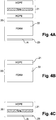
- FIGS 4A-4C illustrate three exemplary embodiments of a heat shield for use in a vehicle component of the invention.
- the reinforcement layer 21 is formed, e.g. compression molded, by including a fiber mat between two HDPE layers.
- a foam layer 22 is arranged, e.g. glued, against the reinforcement layer 21.
- a reflective outer layer 23 in the form of a thin aluminium sheet is fixed, e.g. glued against the foam material.
- Such a heat shield may be welded with its HDPE outer layer to the outer wall of a vehicle component such as a tank or a filler pipe.
- a HDPE layer that does not contain fibers forms the reinforcement layer 21.
- a foam layer 22 is arranged, e.g.
- the reinforcement layer 21 is formed by arranging a fiber mat against/in a HDPE layer.
- a reflective outer layer 23 in the form of a thin aluminium sheet is fixed, e.g. glued against the fibre material.
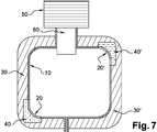
- FIGS 5-7 illustrate an embodiment of the method of the invention for blow-molding a vehicle tank, from a thermoplastic material.
- the heat shield is overmolded on the tank as follows.
- the method comprises adhering a heat shield 20, 20' to a wall of the vehicle tank.
- one or more heat shields 20, 20' are placed in a mold 30, 30'.
- the tank is blow-molded from a tubular wall portion 10, which is brought into the mold by means of a shaping tool 60 of an extrusion die 50.
- the temperature of the heat shields 20, 20' and the mold 30, 30' are such that the reinforcement layer is welded to the thermoplastic material 10 of the tank.
- the Twin Sheet Blow Molding Process can be advantageously used.
- the shield is adhered onto the extruded sheet instead of to the tubular wall portion.
- the heat shields 20, 20' comprise a reinforcement layer made from a thermoplastic material that is welded to the thermoplastic material of the tank, and a heat shielding material which differs from said thermoplastic material of said layer and which is configured for decreasing the transfer of heat through the reinforcement layer to the tank.
- the mold 30, 30' is kept at a predetermined temperature during a predetermined time period for obtaining a good adherence of the reinforcement layer to the wall 10 of the blow-molded tank.
- the heat shield 20, 20' before placing the heat shield 20, 20' in the mold 30, 30', the heat shield 20, 20' is heated to bring the thermoplastic material of the reinforcement layer thereof in a molten state.
- the heat shield 20, 20' may be preformed before positioning the heat shield 20, 20' in the mold 30, 30'.
- the adhering of the heat shield to a vehicle tank or filler pipe comprises welding the heat shield against an outer wall of an already molded vehicle tank or filler pipe.
- the heat shields 20, 20' comprise a heat-insulating layer of a heat insulation material, said heat-insulating layer being arranged against the reinforcement layer.
- the heat insulation material is a foam material.
- the heat shields 20, 20' may comprise a reflective layer, e.g. a metal layer, which forms an outer layer of the heat shield, said reflective layer being configured for reflecting heat radiation.
- a reflective layer may be glued against the reinforcement layer or against the insulation layer, if the latter is present.
- the reflective layer may be laminated together with the reinforcement layer.
- the reflective layer is a thin aluminium sheet.
Landscapes
- Engineering & Computer Science (AREA)
- Mechanical Engineering (AREA)
- Manufacturing & Machinery (AREA)
- Life Sciences & Earth Sciences (AREA)
- Sustainable Development (AREA)
- Sustainable Energy (AREA)
- Chemical & Material Sciences (AREA)
- Combustion & Propulsion (AREA)
- Transportation (AREA)
- Cooling, Air Intake And Gas Exhaust, And Fuel Tank Arrangements In Propulsion Units (AREA)
- Blow-Moulding Or Thermoforming Of Plastics Or The Like (AREA)
- Laminated Bodies (AREA)
Priority Applications (5)
| Application Number | Priority Date | Filing Date | Title |
|---|---|---|---|
| EP14186920.6A EP3000583A1 (de) | 2014-09-29 | 2014-09-29 | Fahrzeugkomponente mit Hitzeschild und Verfahren zur Herstellung davon |
| US15/514,698 US10596744B2 (en) | 2014-09-29 | 2015-09-29 | Method for welding a heat shield during manufacturing of a vehicle component |
| PCT/EP2015/072471 WO2016050794A1 (en) | 2014-09-29 | 2015-09-29 | Method for welding a heat shield during manufacturing of a vehicle component |
| CN201580052897.5A CN106715080A (zh) | 2014-09-29 | 2015-09-29 | 在制造车辆部件期间焊接热屏蔽装置的方法 |
| EP15771108.6A EP3200966B1 (de) | 2014-09-29 | 2015-09-29 | Fahrzeugkomponente mit hitzeschild und verfahren zur herstellung davon |
Applications Claiming Priority (1)
| Application Number | Priority Date | Filing Date | Title |
|---|---|---|---|
| EP14186920.6A EP3000583A1 (de) | 2014-09-29 | 2014-09-29 | Fahrzeugkomponente mit Hitzeschild und Verfahren zur Herstellung davon |
Publications (1)
| Publication Number | Publication Date |
|---|---|
| EP3000583A1 true EP3000583A1 (de) | 2016-03-30 |
Family
ID=51663011
Family Applications (2)
| Application Number | Title | Priority Date | Filing Date |
|---|---|---|---|
| EP14186920.6A Withdrawn EP3000583A1 (de) | 2014-09-29 | 2014-09-29 | Fahrzeugkomponente mit Hitzeschild und Verfahren zur Herstellung davon |
| EP15771108.6A Active EP3200966B1 (de) | 2014-09-29 | 2015-09-29 | Fahrzeugkomponente mit hitzeschild und verfahren zur herstellung davon |
Family Applications After (1)
| Application Number | Title | Priority Date | Filing Date |
|---|---|---|---|
| EP15771108.6A Active EP3200966B1 (de) | 2014-09-29 | 2015-09-29 | Fahrzeugkomponente mit hitzeschild und verfahren zur herstellung davon |
Country Status (4)
| Country | Link |
|---|---|
| US (1) | US10596744B2 (de) |
| EP (2) | EP3000583A1 (de) |
| CN (1) | CN106715080A (de) |
| WO (1) | WO2016050794A1 (de) |
Cited By (2)
| Publication number | Priority date | Publication date | Assignee | Title |
|---|---|---|---|---|
| FR3064216A1 (fr) * | 2017-03-27 | 2018-09-28 | Rm Technologies | Reservoir a carburant sous pression de vehicule automobile hybride |
| WO2019209951A1 (en) * | 2018-04-24 | 2019-10-31 | Intellectual Property Holdings, Llc | Molded vehicle component with integral heat shield and method of making the same |
Families Citing this family (4)
| Publication number | Priority date | Publication date | Assignee | Title |
|---|---|---|---|---|
| CN106346797A (zh) * | 2016-08-31 | 2017-01-25 | 亚普汽车部件股份有限公司 | 中空箱体及其成型方法 |
| DE102018201272A1 (de) | 2018-01-29 | 2019-08-01 | Bayerische Motoren Werke Aktiengesellschaft | Modular aufgebauter Kunststoffbehälter |
| JP7037247B2 (ja) * | 2018-02-22 | 2022-03-16 | 本田技研工業株式会社 | 燃料タンク |
| EP3822061B1 (de) * | 2019-11-18 | 2022-03-23 | Magna Energy Storage Systems GesmbH | Verfahren zur herstellung eines kunststofftanks |
Citations (6)
| Publication number | Priority date | Publication date | Assignee | Title |
|---|---|---|---|---|
| US5020687A (en) * | 1990-02-12 | 1991-06-04 | Solvay Automotive, Inc. | Fabric reinforcement for plastic fuel tanks |
| JP2009067223A (ja) * | 2007-09-13 | 2009-04-02 | Toyota Motor Corp | 燃料タンク |
| US20110037203A1 (en) * | 2008-04-16 | 2011-02-17 | Honda Motor Co., Ltd. | Insert part weld molding method |
| FR2957296A1 (fr) | 2010-03-09 | 2011-09-16 | Inergy Automotive Systems Res | Procede pour fabriquer un reservoir a carburant et son utilisation dans un vehicule hybride |
| WO2013041180A2 (en) * | 2011-09-21 | 2013-03-28 | Kautex Textron Gmbh & Co. Kg | Operating fluid tank for a motor vehicle |
| WO2013047771A1 (ja) * | 2011-09-29 | 2013-04-04 | 富士フイルム株式会社 | 熱線遮蔽材 |
Family Cites Families (16)
| Publication number | Priority date | Publication date | Assignee | Title |
|---|---|---|---|---|
| US5188981A (en) * | 1991-05-28 | 1993-02-23 | Ford Motor Company | Molded article with integral heat shield |
| US6071370A (en) * | 1993-12-27 | 2000-06-06 | Ford Global Technologies, Inc. | Fuel tank with integral heat shield |
| JP3340997B2 (ja) * | 1998-03-04 | 2002-11-05 | リーター アウトモーティブ (インターナツィオナール) アクティエン ゲゼルシャフト | 熱シールドを組み込んだ燃料タンク |
| US6268037B1 (en) * | 1998-10-28 | 2001-07-31 | Acoust-A-Fiber Research And Development, Inc. | Heat shield for blow-molded component |
| US6661339B2 (en) * | 2000-01-24 | 2003-12-09 | Nextreme, L.L.C. | High performance fuel tank |
| US20080169678A1 (en) * | 2004-04-30 | 2008-07-17 | Kyoraku Co., Ltd. | Interior Finishing Panel for Vehicle and Method of Manufacturing the Same |
| JP2008546574A (ja) | 2005-06-28 | 2008-12-25 | イナジー・オートモーティブ・システムズ・リサーチ・(ソシエテ・アノニム) | 内部付属品を備える燃料タンクの製造方法 |
| JP2007231136A (ja) * | 2006-02-28 | 2007-09-13 | Kyoraku Co Ltd | プロピレン系樹脂組成物ならびにその組成物からなるブロー成形パネルおよびそのブロー成形パネルからなる自動車用デッキボード |
| FR2957018B1 (fr) | 2010-03-08 | 2012-10-12 | Inergy Automotive Systems Res | Procede et appareillage pour la fabrication d'un corps creux en matiere plastique a partir de deux feuilles |
| US8967418B2 (en) | 2010-03-09 | 2015-03-03 | Inergy Automotive Systems Research S.A. | Process for manufacturing a fuel tank and use thereof in a hybrid vehicle |
| DE102010016252A1 (de) * | 2010-03-31 | 2011-10-06 | Dr. Ing. H.C. F. Porsche Aktiengesellschaft | Kraftstofftank |
| DE102010017714B4 (de) * | 2010-07-02 | 2014-01-16 | Puky Gmbh & Co. Kg | Blasformsitz und Verfahren zu dessen Herstellung |
| EP2503040A1 (de) * | 2011-03-23 | 2012-09-26 | Autoneum Management AG | Geformte mehrschichtige Verkleidung |
| JP5633889B2 (ja) * | 2013-03-05 | 2014-12-03 | 本田技研工業株式会社 | ブロー成型用金型 |
| FR3003792B1 (fr) | 2013-03-29 | 2015-06-26 | Inergy Automotive Systems Res | Procede pour fabriquer un reservoir a carburant et son utilisation dans un vehicule hybride |
| JP6539429B2 (ja) * | 2013-08-28 | 2019-07-03 | 三菱重工業株式会社 | 可撓性熱制御材料及び推進薬タンク |
-
2014
- 2014-09-29 EP EP14186920.6A patent/EP3000583A1/de not_active Withdrawn
-
2015
- 2015-09-29 CN CN201580052897.5A patent/CN106715080A/zh active Pending
- 2015-09-29 WO PCT/EP2015/072471 patent/WO2016050794A1/en active Application Filing
- 2015-09-29 EP EP15771108.6A patent/EP3200966B1/de active Active
- 2015-09-29 US US15/514,698 patent/US10596744B2/en active Active
Patent Citations (6)
| Publication number | Priority date | Publication date | Assignee | Title |
|---|---|---|---|---|
| US5020687A (en) * | 1990-02-12 | 1991-06-04 | Solvay Automotive, Inc. | Fabric reinforcement for plastic fuel tanks |
| JP2009067223A (ja) * | 2007-09-13 | 2009-04-02 | Toyota Motor Corp | 燃料タンク |
| US20110037203A1 (en) * | 2008-04-16 | 2011-02-17 | Honda Motor Co., Ltd. | Insert part weld molding method |
| FR2957296A1 (fr) | 2010-03-09 | 2011-09-16 | Inergy Automotive Systems Res | Procede pour fabriquer un reservoir a carburant et son utilisation dans un vehicule hybride |
| WO2013041180A2 (en) * | 2011-09-21 | 2013-03-28 | Kautex Textron Gmbh & Co. Kg | Operating fluid tank for a motor vehicle |
| WO2013047771A1 (ja) * | 2011-09-29 | 2013-04-04 | 富士フイルム株式会社 | 熱線遮蔽材 |
Cited By (3)
| Publication number | Priority date | Publication date | Assignee | Title |
|---|---|---|---|---|
| FR3064216A1 (fr) * | 2017-03-27 | 2018-09-28 | Rm Technologies | Reservoir a carburant sous pression de vehicule automobile hybride |
| EP3381730A1 (de) * | 2017-03-27 | 2018-10-03 | RM Technologies | Unter druck stehender kraftstofftank eines hybrid-kraftfahrzeugs |
| WO2019209951A1 (en) * | 2018-04-24 | 2019-10-31 | Intellectual Property Holdings, Llc | Molded vehicle component with integral heat shield and method of making the same |
Also Published As
| Publication number | Publication date |
|---|---|
| EP3200966B1 (de) | 2020-09-09 |
| US10596744B2 (en) | 2020-03-24 |
| WO2016050794A1 (en) | 2016-04-07 |
| CN106715080A (zh) | 2017-05-24 |
| US20170217075A1 (en) | 2017-08-03 |
| EP3200966A1 (de) | 2017-08-09 |
Similar Documents
| Publication | Publication Date | Title |
|---|---|---|
| EP3200966B1 (de) | Fahrzeugkomponente mit hitzeschild und verfahren zur herstellung davon | |
| JP5026265B2 (ja) | 付属品をプラスチック製燃料タンクに結合させる方法 | |
| JP6409887B2 (ja) | 圧力容器 | |
| US20030124281A1 (en) | Liquid-or vapor-conducting system with a jointing zone made from a coextruded multilayer composite | |
| US5308571A (en) | Method of molding an article with integral heat shield | |
| US9987797B2 (en) | Method for manufacturing a fuel tank and fuel tank | |
| JP5899121B2 (ja) | 燃料タンクの製造方法、およびハイブリッド車両におけるその使用 | |
| US20020020487A1 (en) | Adapter for welding objects to plastic | |
| US20060151505A1 (en) | Fuel tank for motor vehicle and method for producing the same | |
| JP2008524014A (ja) | 少なくとも1つの溶着部を含む多層中空本体の製造方法 | |
| RU2009142614A (ru) | Составная упаковка "bag-in-container", изготовленная способом выдувного формования, имеющая точку крепления пакета, способ и устройство для ее изготовления | |
| JP2006192894A (ja) | ソケットの製造方法 | |
| US20150239198A1 (en) | Attaching structure of insert member to blow molded article | |
| JP2008155587A (ja) | 中空樹脂成形品の製造方法 | |
| JP6929447B2 (ja) | 液体容器および液体容器を製造するための方法 | |
| KR102381103B1 (ko) | 자동차용 가압 유체 저장 탱크용 내부 인클로저 | |
| US5674603A (en) | Molded article with integral heat shield | |
| JP2008155588A (ja) | 中空樹脂成形品およびその製造方法 | |
| US20170122483A1 (en) | Tube liner with a fleece-laminated film web connected to form a film tube | |
| KR102398676B1 (ko) | 3차원 구조체와 이의 제조 방법 | |
| RU49944U1 (ru) | Композитная труба | |
| JPS5850744Y2 (ja) | 容器 | |
| US20190322168A1 (en) | Molded Vehicle Component With Integral Heat Shield and Method of Making the Same |
Legal Events
| Date | Code | Title | Description |
|---|---|---|---|
| PUAI | Public reference made under article 153(3) epc to a published international application that has entered the european phase |
Free format text: ORIGINAL CODE: 0009012 |
|
| AK | Designated contracting states |
Kind code of ref document: A1 Designated state(s): AL AT BE BG CH CY CZ DE DK EE ES FI FR GB GR HR HU IE IS IT LI LT LU LV MC MK MT NL NO PL PT RO RS SE SI SK SM TR |
|
| AX | Request for extension of the european patent |
Extension state: BA ME |
|
| STAA | Information on the status of an ep patent application or granted ep patent |
Free format text: STATUS: THE APPLICATION IS DEEMED TO BE WITHDRAWN |
|
| 18D | Application deemed to be withdrawn |
Effective date: 20161001 |