EP3000563A1 - Machine-outil portative fonctionnant sur batterie ayant au moins une partie de boitier - Google Patents
Machine-outil portative fonctionnant sur batterie ayant au moins une partie de boitier Download PDFInfo
- Publication number
- EP3000563A1 EP3000563A1 EP15178052.5A EP15178052A EP3000563A1 EP 3000563 A1 EP3000563 A1 EP 3000563A1 EP 15178052 A EP15178052 A EP 15178052A EP 3000563 A1 EP3000563 A1 EP 3000563A1
- Authority
- EP
- European Patent Office
- Prior art keywords
- battery
- housing part
- hand tool
- operated hand
- tool
- Prior art date
- Legal status (The legal status is an assumption and is not a legal conclusion. Google has not performed a legal analysis and makes no representation as to the accuracy of the status listed.)
- Granted
Links
- 238000003754 machining Methods 0.000 claims description 11
- 238000003780 insertion Methods 0.000 claims description 6
- 230000037431 insertion Effects 0.000 claims description 6
- 238000004891 communication Methods 0.000 description 12
- 238000012545 processing Methods 0.000 description 9
- 238000004519 manufacturing process Methods 0.000 description 8
- 238000005286 illumination Methods 0.000 description 7
- 238000001816 cooling Methods 0.000 description 6
- 238000013461 design Methods 0.000 description 4
- 230000005540 biological transmission Effects 0.000 description 3
- WHXSMMKQMYFTQS-UHFFFAOYSA-N Lithium Chemical compound [Li] WHXSMMKQMYFTQS-UHFFFAOYSA-N 0.000 description 2
- HBBGRARXTFLTSG-UHFFFAOYSA-N Lithium ion Chemical compound [Li+] HBBGRARXTFLTSG-UHFFFAOYSA-N 0.000 description 2
- 238000004026 adhesive bonding Methods 0.000 description 2
- 238000005520 cutting process Methods 0.000 description 2
- 238000011161 development Methods 0.000 description 2
- 230000018109 developmental process Effects 0.000 description 2
- 229910052744 lithium Inorganic materials 0.000 description 2
- 229910001416 lithium ion Inorganic materials 0.000 description 2
- 238000000034 method Methods 0.000 description 2
- RTAQQCXQSZGOHL-UHFFFAOYSA-N Titanium Chemical compound [Ti] RTAQQCXQSZGOHL-UHFFFAOYSA-N 0.000 description 1
- JDZCKJOXGCMJGS-UHFFFAOYSA-N [Li].[S] Chemical compound [Li].[S] JDZCKJOXGCMJGS-UHFFFAOYSA-N 0.000 description 1
- 239000003086 colorant Substances 0.000 description 1
- 238000010276 construction Methods 0.000 description 1
- 230000001419 dependent effect Effects 0.000 description 1
- 239000000428 dust Substances 0.000 description 1
- 238000005304 joining Methods 0.000 description 1
- GELKBWJHTRAYNV-UHFFFAOYSA-K lithium iron phosphate Chemical compound [Li+].[Fe+2].[O-]P([O-])([O-])=O GELKBWJHTRAYNV-UHFFFAOYSA-K 0.000 description 1
- 230000003287 optical effect Effects 0.000 description 1
- 239000011236 particulate material Substances 0.000 description 1
- 229920000642 polymer Polymers 0.000 description 1
- 238000003466 welding Methods 0.000 description 1
- 238000004804 winding Methods 0.000 description 1
Images

Classifications
-
- B—PERFORMING OPERATIONS; TRANSPORTING
- B25—HAND TOOLS; PORTABLE POWER-DRIVEN TOOLS; MANIPULATORS
- B25F—COMBINATION OR MULTI-PURPOSE TOOLS NOT OTHERWISE PROVIDED FOR; DETAILS OR COMPONENTS OF PORTABLE POWER-DRIVEN TOOLS NOT PARTICULARLY RELATED TO THE OPERATIONS PERFORMED AND NOT OTHERWISE PROVIDED FOR
- B25F5/00—Details or components of portable power-driven tools not particularly related to the operations performed and not otherwise provided for
-
- B—PERFORMING OPERATIONS; TRANSPORTING
- B23—MACHINE TOOLS; METAL-WORKING NOT OTHERWISE PROVIDED FOR
- B23D—PLANING; SLOTTING; SHEARING; BROACHING; SAWING; FILING; SCRAPING; LIKE OPERATIONS FOR WORKING METAL BY REMOVING MATERIAL, NOT OTHERWISE PROVIDED FOR
- B23D49/00—Machines or devices for sawing with straight reciprocating saw blades, e.g. hacksaws
- B23D49/10—Hand-held or hand-operated sawing devices with straight saw blades
- B23D49/16—Hand-held or hand-operated sawing devices with straight saw blades actuated by electric or magnetic power or prime movers
- B23D49/162—Pad sawing devices
-
- B—PERFORMING OPERATIONS; TRANSPORTING
- B23—MACHINE TOOLS; METAL-WORKING NOT OTHERWISE PROVIDED FOR
- B23D—PLANING; SLOTTING; SHEARING; BROACHING; SAWING; FILING; SCRAPING; LIKE OPERATIONS FOR WORKING METAL BY REMOVING MATERIAL, NOT OTHERWISE PROVIDED FOR
- B23D51/00—Sawing machines or sawing devices working with straight blades, characterised only by constructional features of particular parts; Carrying or attaching means for tools, covered by this subclass, which are connected to a carrier at both ends
- B23D51/01—Sawing machines or sawing devices working with straight blades, characterised only by constructional features of particular parts; Carrying or attaching means for tools, covered by this subclass, which are connected to a carrier at both ends characterised by the handle
-
- B—PERFORMING OPERATIONS; TRANSPORTING
- B23—MACHINE TOOLS; METAL-WORKING NOT OTHERWISE PROVIDED FOR
- B23D—PLANING; SLOTTING; SHEARING; BROACHING; SAWING; FILING; SCRAPING; LIKE OPERATIONS FOR WORKING METAL BY REMOVING MATERIAL, NOT OTHERWISE PROVIDED FOR
- B23D51/00—Sawing machines or sawing devices working with straight blades, characterised only by constructional features of particular parts; Carrying or attaching means for tools, covered by this subclass, which are connected to a carrier at both ends
- B23D51/16—Sawing machines or sawing devices working with straight blades, characterised only by constructional features of particular parts; Carrying or attaching means for tools, covered by this subclass, which are connected to a carrier at both ends of drives or feed mechanisms for straight tools, e.g. saw blades, or bows
-
- B—PERFORMING OPERATIONS; TRANSPORTING
- B25—HAND TOOLS; PORTABLE POWER-DRIVEN TOOLS; MANIPULATORS
- B25F—COMBINATION OR MULTI-PURPOSE TOOLS NOT OTHERWISE PROVIDED FOR; DETAILS OR COMPONENTS OF PORTABLE POWER-DRIVEN TOOLS NOT PARTICULARLY RELATED TO THE OPERATIONS PERFORMED AND NOT OTHERWISE PROVIDED FOR
- B25F5/00—Details or components of portable power-driven tools not particularly related to the operations performed and not otherwise provided for
- B25F5/02—Construction of casings, bodies or handles
Definitions
- the invention relates to a battery-powered hand tool with at least one first housing part.
- the battery-operated hand tool according to the invention has the advantage of being very compact and handy.
- the advantage of the battery-operated hand tool machine is the development of a new user group, especially women and people who previously had reservations and no experience with hand tool machines of this kind.
- the battery-powered hand tool according to the invention can be designed as a jigsaw.
- at least one rechargeable battery is provided as an energy source for the battery-operated handheld power tool.
- the rechargeable battery comprises at least one battery cell.
- the at least one battery cell nominally has a battery voltage which is between 2V and 7.5V, in particular between 3V and 4.5V is, but preferably 3.6 V is. Battery voltage fluctuations are not taken into account here.
- At least one second housing part receives at least one electromotive drive, a pusher, and a machining tool holder.
- the electronically commutated electric motor is arranged above the pusher device.
- At least the first housing part is connected to the second housing part in an advantageous manner.
- the electric motor drive drives at least one motor shaft, wherein the motor shaft defines a motor axis which is coaxial with the motor shaft.
- the rechargeable battery defines a battery axis, which is in particular coaxial with the insertion direction of the rechargeable battery. It is proposed that the motor axis and the battery axis are in particular parallel to each other. By “parallel” is to be understood here that the motor axis and the battery axis are arranged at an angle to each other, which is between 0 and 20 °. These specifications take no account of manufacturing tolerances.
- the push rod defines a lifting axis which is winkling, in particular at right angles to the motor axis.
- the lifting axis is winkling, in particular at right angles to the battery axis.
- the first housing part is designed as a handle.
- a "handle” is to be understood here in particular as a component that can essentially be enclosed by a hand of an operator of the battery-operated handheld power tool in order to guide the battery-operated handheld power tool.
- the first housing part is substantially entirely in the hands of an operator. This is achieved by the compact design of the battery-powered power tool.
- the handle has a circumference U handle , which is between 80 and 170 mm, especially between 110 and 150 mm, but preferably 130 mm.
- a circumference U handle which is between 80 and 170 mm, especially between 110 and 150 mm, but preferably 130 mm.
- the compactness of the battery-operated hand tool machine advantageously manifests itself in a length I housing which has the first housing part.
- the length I housing of the first housing part is between 70 mm and 130 mm, especially between 80 and 115 mm.
- the length I housing of the first housing part is preferably 100 mm.
- the rechargeable battery is integrated with the majority of a length I Batt , in particular with its entire length I Batt in the first housing part.
- a second handle is arranged on the second housing part.
- the handle may be in the form of an ergonomically shaped knob.
- annular lighting device is arranged on the second housing part. This can be advantageously illuminated an environment such as a workplace.
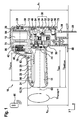
- FIG. 1 shows a trained as a jigsaw battery-powered power tool
- a rechargeable battery 14 can be inserted.
- the rechargeable battery 14 is inserted or inserted in the assembled state in the first housing part 12, wherein the rechargeable battery 14 is inserted with its entire battery length I Batt in the first housing part 12.
- the insertion direction of the rechargeable battery 14 extends substantially coaxially to a main extension direction x of the first housing part 12.
- the rechargeable battery 14 serves as a power supply for the battery-powered power tool 10.
- the rechargeable battery 14 includes in the exemplary embodiment a battery cell having a nominal battery voltage, the between 2V and 7.5V, in particular between 3V and 4.5V, but is preferably 3.6V.
- the values of the battery voltage do not take into account possible battery voltage fluctuations. For example, the charging voltage may be higher, while in operation of the battery powered hand tool 10, the voltage drops to less than 3.6V.
- the battery cell of the rechargeable battery 14 is in particular a lithium ion battery cell.
- Lithium ion battery cells are characterized by a high energy density and thermal stability even at high loads, which means high performance.
- Another big advantage is the low self-discharge, which also means that the battery cells are ready for use even with longer service lives.
- the rechargeable battery 14 from a lithium-air battery cell, a lithium-sulfur battery cell, a lithium polymer battery cell, a lithium-iron-phosphate battery cell, a lithium titanate battery cell or the like consists. Furthermore, the rechargeable battery 14 may be realized in a different geometric embodiment than shown.
- the rechargeable battery 14 is in the embodiment in FIG. 1 designed as a replaceable rechargeable battery 14. It is also conceivable that the rechargeable battery 14 is designed as an integrated unit.
- an electronics unit 14 is further arranged.
- the electronic unit 14 is provided to energize, control and / or regulate an electric motor drive 18.
- the electromotive drive 18 is designed as an electronically commutated electric motor.
- the electronic unit 14 power components 20 and a sensor element 22 are arranged on the electronic unit 14 power components 20 and a sensor element 22 are arranged.
- the sensor element 22 can detect a physical quantity and convert the physical quantity into a sensor signal.
- a processor 24 processes the sensor signals.
- the electronic unit 14 is aligned with its length I board parallel to the insertion direction of the rechargeable battery 14 and extends substantially coaxially to the main extension direction x of the first housing part 12th
- the electronically commutated electric motor 18 is arranged in a second housing part 26.
- the electronically commutated electric motor 18 drives a motor shaft 28.
- the electronically commutated electric motor 18 is designed in the embodiment as an internal rotor. In motors of this type, a stator carrying the live windings is attached to a motor housing. A rotor carrying the permanent magnets is connected to the motor shaft 28.
- the advantages of the internal rotor motor are a high speed to be achieved with high power density. But it is also conceivable that the electronically commutated electric motor 18 is designed as an external rotor motor or brush motor.
- the electronically commutated electric motor 18 is connected via a belt drive with a pusher 30.
- the electronically commutated electric motor 18 is arranged above the pusher 30.
- the electronically commutated electric motor 18 is gearless connected to the pusher.
- gearless is to be understood that the electronically commutated electric motor 18 is connected to the pusher 30 without the interposition of a conventional transmission, such as a planetary gear, bevel gear or spur gear.
- a conventional transmission such as For example, a planetary gear or a spur gear or the like, is connected to the pusher.
- the pusher 30 comprises a peg element 32, a pusher element 34, as well as a push rod 36.
- the push rod 36 has a machining tool holder 38.
- the machining tool holder 38 may receive a machining tool 39.
- the machining tool is in the embodiment in FIG. 1 a saw blade.
- the machining tool 38 is realized as another embodiment which appears expedient to the person skilled in the art.
- the belt drive comprises a first pulley 40 which sits on the motor shaft 18.
- the first pulley 40 is connected via a belt 42 to a second pulley 44 which sits on a second shaft 46.
- the belt 42 transmits the torque from the motor shaft 18 to the second shaft 46.
- a first gear 48 is arranged, which meshes with a second gear 50.
- the second gear 50 is connected to a crank mechanism 52, which engages with the aid of the pin member 32 in the thrust element 34.
- the rotational movement of the second shaft 46 is thus converted into a lifting movement of the pusher 30.
- the push rod 36 is mounted via a first bearing 54 and a second bearing 56.
- the first housing part 12 is connected to the second housing part 26. It is conceivable that the first housing part and the second housing part are designed in one piece or as separate component units. If the first housing part 12 and the second housing part 26 are designed as separate component units, the connection of the two housing parts 12, 26 usually takes place by screwing. But it is also conceivable that both housing parts 12, 26 are connected by other joining techniques such as riveting, welding or gluing.
- the motor shaft 28 defines a motor shaft 58.
- the motor shaft 58 is coaxial with the motor shaft 28.
- the rechargeable battery 14 defines a battery axis 60.
- the battery axis 60 is coaxial with the direction of insertion of the rechargeable battery 14.
- the motor shaft 58 and the battery axis 60 are in the embodiment of FIG. 1 parallel to each other. By “parallel” is meant here that the two axes 58, 60 are arranged at an angle to each other, which is between 0 and 20 °. These specifications take no account of manufacturing tolerances.
- the push rod 36 defines a lifting axis 62 which is winkling, in particular at right angles to the motor shaft 58.
- the lifting axis 62 is winkling, in particular at right angles to the battery axis 60.
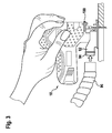
- the first housing part 12 forms a handle 70.
- the handle 70 is designed according to the invention such that the handle 70 fits almost in every hand, even in the very small person. Under “very small” should be understood here a body size of about 100 to 160cm, especially from about 130 to 140cm. In particular, the handle 70 should be able to be almost completely enclosed by the hand of an operator.
- the handle 26 has a circumference U handle which is between 80 and 170 mm, in particular between 110 and 150, but is preferably 130 mm. With this scope, the battery powered hand tool 10 fits in every hand. These specifications take no account of possible manufacturing tolerances.
- the first housing part 12 has a length I housing which is between 70 and 130 mm, in particular between 80 and 115 mm, but is preferably 100 mm.
- the rechargeable battery 14 is inserted with its entire battery length I Batt in the first housing part 12.
- I Batt battery length
- a switching element 72 is attached to the second housing part 26 of the battery-operated hand tool 10.
- the switching element 72 may be designed as a toggle switch, as a slide switch, as a button or the like. But it is also conceivable that the switch as a deadman switch or paddles in the Handle area is executed.
- a lock can fix the switch in an on position.
- the electronics unit 16 Upon actuation of the switching element 72, the electronics unit 16 is turned on.
- the cooling plays an increasingly important role in hand tool machines with electronically commutated electric motors 18.
- the cooling can be passive or active. In passive cooling, the removal of thermal energy by convection takes place. With active cooling, the thermal energy of the component to be cooled is removed by means of a cooling system.
- a fan 74 is mounted on the motor shaft 28 and disposed between the electronically commutated electric motor 18 and the first pulley 40. But it is also conceivable that the fan 72 is not attached to the motor shaft 28, but is connected via elements such as belts or gears to the motor shaft 28. It is equally conceivable that other cooling systems such as Peltier elements, heat sinks, additional actuators with air guide elements or the like are used.
- a lighting device 75 is arranged.
- the lighting device 75 may also be arranged on the first housing part 12.
- the lighting device 75 can illuminate a working field, but also project optical information onto an environment.
- the lighting device 75 may comprise both a single LED, as well as a plurality of LEDs.
- the LEDs can be provided in various designs and sizes.
- the illumination device 75 can also be embodied as a punctiform light source. But it is also conceivable that the lighting device 75 is designed as a projection device.
- the lighting device 75 may have lighting elements which may be arranged in different shapes on the second housing part 26 and / or on the first housing part 12.
- the illumination device 75 can be embodied as a light guide, which can display not only an illumination of a work area but also a cutting path, a cutting line or the like.
- the rotational speed of the electronically commutated electric motor 18 is between 12,000 rpm and 30,000 rpm, in particular between 15,000 rpm and 25,000 rpm.
- the rotational speed of the electronically commutated electric motor 18 is preferably 18,000 rpm.
- the speed can be reduced via an actuator.
- an operating mode such as an e-mode or a boost mode, can be set via an actuating element.
- An “ecomodus” is to be understood in particular as a mode in which the electronically commutated electric motor is operated particularly efficiently.
- efficiency is meant here that the electronically commutated electric motor is operated at the optimum operating point.
- boost mode is to be understood as a mode in which the electronically commutated electric motor is operated particularly efficiently.
- the power requirement on the electronically commutated electric motor can be limited in time and may be in the overload range of the electronically commutated electric motor.
- the boost mode can be activated via a switch.
- the power overshoot of the electronically commutated electric motor is between 10% and 100%, especially between 20% and 50%, but preferably at 33%.
- the time limit of the boost mode is between 0 and 5min, especially between 0 and 2.5min.
- the time limit of the boost mode is preferably between 30 s and 1 min.
- the stroke of the pusher 30 is optimally between 1500 and 6000 mm, especially between 2500 and 5500 mm. Preferably, however, the stroke of the pusher 30 is 4500 mm.
- the battery-powered hand tool 10 has a communication module 78 for establishing a data transmission connection.
- the communication module 78 sends data characterizing an environment-specific parameter and / or a tool-specific characteristic and / or a characteristic parameter affecting specific parameter to an external communication and / or data processing unit 80.
- the battery-operated handheld power tool 10 is equipped with an interface 82 which is intended, a data exchange, in particular an electronic Data exchange between the battery-powered power tool 10, in particular the electronics 16 of the battery-powered power tool 10 and the external communication and / or data processing unit 80 to allow.
- the data exchange between the electronics 16 and the external communication and / or data processing unit 80 preferably takes place wirelessly, for example with the aid of a Bluetooth connection, Bluetooth low energy, a WLAN connection, an NFC connection, an infrared connection or the like.
- the electronics 16 controls and / or regulates the electronically commutated electric motor 18 preferably as a function of the parameters of the battery-operated handheld power tool 10.
- the external communication and / or data processing unit 80 is preferably designed as a smart interface, for example as a smartphone, which has an app for communication with the interface 82.
- the external communication and / or data processing unit 80 as an external, transportable communication and / or data processing unit, as permanently installed communication and / or data processing unit or as further, a professional appear appropriate sense centralized or decentralized communication and / or data processing unit is formed. It can thus be advantageous to enable synchronization of electronic data.
- Settings stored in the external communication and / or data processing unit 80 can be transmitted, for example, directly to the battery-operated handheld power tool 10, such as a set speed, a maximum power or the like.
- a second handle 84 is provided on the second housing part 26.
- the second handle 84 is formed in particular as a knob, which also gives an attractive appearance in terms of appearance.
- the second handle 84 is designed such that it lies particularly ergonomically in the hand of the operator.
- a height h 1 of the second housing part 26 defines a height of the battery-operated hand tool 10.
- the height h 1 is determined by the geometric extension of the second housing part 26 defined by a first handle housing wall 86 to a bottom plate 88.
- the height h 1 of the second housing part 26 is in this case between 80 and 130 mm, especially between 90 and 115 mm.
- the height h 1 of the second housing part 26 is preferably 100 mm.
- a height h 2 of the first housing part 12 is defined by the geometric extent of a second handle housing wall 90 to the bottom plate 88.
- the height h 1 of the first housing part 12 is in this case between 50 and 90 mm, especially between 60 and 80 mm.
- the height h 2 of the first housing part 12 is preferably 70 mm.
- the bottom plate 88 is arranged straight in the embodiment.
- straight is to be understood here that the bottom plate 88 is disposed at an angle of 90 ° to the lifting axis 62. But it is also conceivable that the bottom plate 88 is disposed at an angle of 0 to 45 ° to the lifting axis 62. These specifications take no account of manufacturing tolerances. An angular arrangement allows in particular a production of oblique cuts.
- FIG. 2 shows a second embodiment of the battery-powered power tool 10.
- the main difference from the first embodiment in FIG. 1 is the arrangement of the electronics unit 16, the electronically commutated electric motor 18 and the fan 74th
- the electronic unit 16 is in the embodiment in FIG. 2 in the first housing part 12, which is designed as a handle 70, arranged.
- the electronic unit 14 is aligned with its length I board at an angle, in particular at right angles, to the insertion direction of the rechargeable battery 14 and extends substantially at an angle, in particular at right angles, to the main extension direction x of the first housing part 12.
- the electronically commutated electric motor 18 is together with the fan 74 and the switching element 72 in the embodiment in FIG. 2 also arranged in the first housing part 12. This is a very compact design of battery-powered hand tool 10 possible because only the gears 48, 50, the crank mechanism 51, the bearings 54, 56, the pusher 30 and the machining tool holder 38 are housed in the second housing part 26.
- a height h 1 of the battery powered hand tool 10 is defined by the geometric extent of the battery powered hand tool 10 from the first handle housing wall 86 to the bottom plate 88.
- the height h 1 of the battery-powered hand tool 10 is in this case between 55 and 95 mm, especially between 65 and 85 mm.
- the height h 1 of the battery-operated handheld power tool 10 is preferably 75 mm.
- FIG. 3 shows a third embodiment of the battery-powered power tool 10.
- the battery-powered power tool 10 has a suction device 92 for a suction, for example, of particulate material.
- the suction device 92 has a connection element 94, which is provided in particular for connecting the suction device 92 to an external dust device 96.
- the battery-powered hand tool 10 is designed as a pendulum hoist.
- the movements of the machining tool 39 always run simultaneously in a vertical and in a horizontal direction.
- one of the vertical directions is linked to one of the horizontal directions, so that a pendulum saw movement is performed.
- An annular lighting device 100 is arranged on the second housing part 26 on a side facing the machining tool holder 38.
- the annular lighting device 100 is formed as a closed light ring.
- the annular lighting device 100 can also be designed as a non-closed illuminated ring, such as a light clip.
- the annular lighting device 100 may also be arranged on the first housing part 12.
- the annular lighting device 100 can also be arranged on the machining tool holder 38.
- the annular lighting device 100 may be connected to the second housing part 26 by gluing, latching, Be connected terminals, clips or the like.
- the annular lighting device 100 may be designed as a light guide.
- the light emitted from the annular illumination device 100 may have different colors.
- the light emitted from the annular illumination device 100 may vary in brightness.
- the light emitted by the annular illumination device 100 may be a flashing light that periodically changes the brightness.
Landscapes
- Engineering & Computer Science (AREA)
- Mechanical Engineering (AREA)
- Details Of Spanners, Wrenches, And Screw Drivers And Accessories (AREA)
- Battery Mounting, Suspending (AREA)
Applications Claiming Priority (1)
| Application Number | Priority Date | Filing Date | Title |
|---|---|---|---|
| DE102014219571.3A DE102014219571A1 (de) | 2014-09-26 | 2014-09-26 | Batteriebetriebene Handwerkzeugmaschine mit mindestens einem ersten Gehäuseteil |
Publications (2)
| Publication Number | Publication Date |
|---|---|
| EP3000563A1 true EP3000563A1 (fr) | 2016-03-30 |
| EP3000563B1 EP3000563B1 (fr) | 2017-06-21 |
Family
ID=53886842
Family Applications (1)
| Application Number | Title | Priority Date | Filing Date |
|---|---|---|---|
| EP15178052.5A Active EP3000563B1 (fr) | 2014-09-26 | 2015-07-23 | Machine-outil portative fonctionnant sur batterie ayant au moins une partie de boitier |
Country Status (2)
| Country | Link |
|---|---|
| EP (1) | EP3000563B1 (fr) |
| DE (1) | DE102014219571A1 (fr) |
Cited By (7)
| Publication number | Priority date | Publication date | Assignee | Title |
|---|---|---|---|---|
| WO2019211133A1 (fr) * | 2018-05-04 | 2019-11-07 | Robert Bosch Gmbh | Boîtier de scie sauteuse |
| USD887806S1 (en) | 2018-04-03 | 2020-06-23 | Milwaukee Electric Tool Corporation | Jigsaw |
| EP3715032A1 (fr) * | 2019-03-29 | 2020-09-30 | Techtronic Cordless GP | Scie alternative |
| US10835972B2 (en) | 2018-03-16 | 2020-11-17 | Milwaukee Electric Tool Corporation | Blade clamp for power tool |
| US11014176B2 (en) | 2018-04-03 | 2021-05-25 | Milwaukee Electric Tool Corporation | Jigsaw |
| EP4008490A1 (fr) * | 2020-12-03 | 2022-06-08 | Andreas Stihl AG & Co. KG | Logement pour accueillir un module de communication |
| EP4241923A1 (fr) * | 2022-03-10 | 2023-09-13 | Robert Bosch GmbH | Machine-outil portative dotée d'un éclairage de champ de travail |
Families Citing this family (1)
| Publication number | Priority date | Publication date | Assignee | Title |
|---|---|---|---|---|
| DE102022206700A1 (de) | 2022-06-30 | 2024-01-04 | Robert Bosch Gesellschaft mit beschränkter Haftung | Werkzeugmaschinenvorrichtung, Werkzeugmaschine und Werkzeugmaschinensystem |
Citations (14)
| Publication number | Priority date | Publication date | Assignee | Title |
|---|---|---|---|---|
| US1948109A (en) * | 1932-05-04 | 1934-02-20 | Emil F Hager | Cutting device |
| EP1325790A2 (fr) * | 2002-01-02 | 2003-07-09 | Black & Decker Inc. | Scie sauteuse |
| EP1477282A1 (fr) * | 2002-01-21 | 2004-11-17 | Hitachi Koki Co., Ltd. | Outil electrique |
| US20050077878A1 (en) * | 2003-10-14 | 2005-04-14 | Dave Carrier | Protection methods, protection circuits and protective devices for secondary batteries, a power tool, charger and battery pack adapted to provide protection against fault conditions in the battery pack |
| US20070180711A1 (en) * | 2003-09-19 | 2007-08-09 | Keith Park | Jigsaw actuation mechanism for imparting scrolling, orbital and reciprocating movement |
| US20080315693A1 (en) * | 2007-01-18 | 2008-12-25 | Hiroki Uchida | Cordless power tool |
| DE202009010017U1 (de) * | 2008-08-06 | 2009-11-05 | Chervon Ltd., Wanchai | Handsäge mit hin- und hergehendem Sägeblatt |
| DE102009018589A1 (de) * | 2009-04-23 | 2011-01-05 | Metabowerke Gmbh | Handgeführtes Elektrowerkzeug |
| WO2011035950A1 (fr) * | 2009-09-23 | 2011-03-31 | Robert Bosch Gmbh | Machine-outil, notamment machine-outil à main |
| DE102009055411A1 (de) * | 2009-12-30 | 2011-07-07 | Robert Bosch GmbH, 70469 | Handwerkzeugmaschinenvorrichtung mit einer Spanblasvorrichtung |
| WO2012135608A1 (fr) * | 2011-04-01 | 2012-10-04 | Milwaukee Electric Tool Corporation | Scie alternative, telle qu'une scie sauteuse |
| US20130063051A1 (en) * | 2010-04-07 | 2013-03-14 | Black & Decker Inc. | Power Tool with Light Unit |
| DE112009005440T5 (de) | 2009-12-14 | 2013-04-25 | Robert Bosch Tool Corporation | Stichsäge |
| WO2014119211A1 (fr) * | 2013-02-01 | 2014-08-07 | 株式会社マキタ | Outil coupant |
-
2014
- 2014-09-26 DE DE102014219571.3A patent/DE102014219571A1/de active Pending
-
2015
- 2015-07-23 EP EP15178052.5A patent/EP3000563B1/fr active Active
Patent Citations (14)
| Publication number | Priority date | Publication date | Assignee | Title |
|---|---|---|---|---|
| US1948109A (en) * | 1932-05-04 | 1934-02-20 | Emil F Hager | Cutting device |
| EP1325790A2 (fr) * | 2002-01-02 | 2003-07-09 | Black & Decker Inc. | Scie sauteuse |
| EP1477282A1 (fr) * | 2002-01-21 | 2004-11-17 | Hitachi Koki Co., Ltd. | Outil electrique |
| US20070180711A1 (en) * | 2003-09-19 | 2007-08-09 | Keith Park | Jigsaw actuation mechanism for imparting scrolling, orbital and reciprocating movement |
| US20050077878A1 (en) * | 2003-10-14 | 2005-04-14 | Dave Carrier | Protection methods, protection circuits and protective devices for secondary batteries, a power tool, charger and battery pack adapted to provide protection against fault conditions in the battery pack |
| US20080315693A1 (en) * | 2007-01-18 | 2008-12-25 | Hiroki Uchida | Cordless power tool |
| DE202009010017U1 (de) * | 2008-08-06 | 2009-11-05 | Chervon Ltd., Wanchai | Handsäge mit hin- und hergehendem Sägeblatt |
| DE102009018589A1 (de) * | 2009-04-23 | 2011-01-05 | Metabowerke Gmbh | Handgeführtes Elektrowerkzeug |
| WO2011035950A1 (fr) * | 2009-09-23 | 2011-03-31 | Robert Bosch Gmbh | Machine-outil, notamment machine-outil à main |
| DE112009005440T5 (de) | 2009-12-14 | 2013-04-25 | Robert Bosch Tool Corporation | Stichsäge |
| DE102009055411A1 (de) * | 2009-12-30 | 2011-07-07 | Robert Bosch GmbH, 70469 | Handwerkzeugmaschinenvorrichtung mit einer Spanblasvorrichtung |
| US20130063051A1 (en) * | 2010-04-07 | 2013-03-14 | Black & Decker Inc. | Power Tool with Light Unit |
| WO2012135608A1 (fr) * | 2011-04-01 | 2012-10-04 | Milwaukee Electric Tool Corporation | Scie alternative, telle qu'une scie sauteuse |
| WO2014119211A1 (fr) * | 2013-02-01 | 2014-08-07 | 株式会社マキタ | Outil coupant |
Cited By (8)
| Publication number | Priority date | Publication date | Assignee | Title |
|---|---|---|---|---|
| US10835972B2 (en) | 2018-03-16 | 2020-11-17 | Milwaukee Electric Tool Corporation | Blade clamp for power tool |
| USD887806S1 (en) | 2018-04-03 | 2020-06-23 | Milwaukee Electric Tool Corporation | Jigsaw |
| US11014176B2 (en) | 2018-04-03 | 2021-05-25 | Milwaukee Electric Tool Corporation | Jigsaw |
| US11813682B2 (en) | 2018-04-03 | 2023-11-14 | Milwaukee Electric Tool Corporation | Jigsaw |
| WO2019211133A1 (fr) * | 2018-05-04 | 2019-11-07 | Robert Bosch Gmbh | Boîtier de scie sauteuse |
| EP3715032A1 (fr) * | 2019-03-29 | 2020-09-30 | Techtronic Cordless GP | Scie alternative |
| EP4008490A1 (fr) * | 2020-12-03 | 2022-06-08 | Andreas Stihl AG & Co. KG | Logement pour accueillir un module de communication |
| EP4241923A1 (fr) * | 2022-03-10 | 2023-09-13 | Robert Bosch GmbH | Machine-outil portative dotée d'un éclairage de champ de travail |
Also Published As
| Publication number | Publication date |
|---|---|
| DE102014219571A1 (de) | 2016-03-31 |
| EP3000563B1 (fr) | 2017-06-21 |
Similar Documents
| Publication | Publication Date | Title |
|---|---|---|
| EP3000563B1 (fr) | Machine-outil portative fonctionnant sur batterie ayant au moins une partie de boitier | |
| EP3296065B1 (fr) | Machine-outil portative à entraînement électromotorique en tant qu'entraînement direct | |
| EP2933063B1 (fr) | Machine-outil portative dotée d'un moteur électrique commuté électroniquement | |
| DE102014211046A1 (de) | System mindestens umfassend einen elektronisch kommutierten Elektromotor einer definierten Baugröße und eine wiederaufladbare Batterie mindestens einer Spannungsklasse | |
| DE112013006566B4 (de) | Elektrisches Werkzeug | |
| DE102015218447A1 (de) | Akkupack für eine Handwerkzeugmaschine | |
| DE102017109598A1 (de) | Kraftwerkzeug | |
| EP3331345B1 (fr) | Taille-haie | |
| DE102013219450A1 (de) | Batteriebetriebener Exzenterschleifer mit einem elektronisch kommutierten Elektromotor | |
| WO2019170331A1 (fr) | Machine-outil portative | |
| DE102019212865A1 (de) | Elektromotor sowie elektrisches Bearbeitungsgerät mit einem Elektromotor | |
| EP2998073B1 (fr) | Machine-outil portative fonctionnant sur batterie ayant au moins une partie de carter moteur | |
| DE102015201575A1 (de) | Oberfräse mit einer Steuer- und/oder Regeleinheit | |
| DE102018219928A1 (de) | Antriebsmodul, Werkzeugmodulsystem mit einem Antriebsmodul und Verfahren zum Betrieb eines Antriebsmoduls | |
| DE102021201621A1 (de) | Elektrisches Bearbeitungsgerät zum wahlweisen Betrieb mit zumindest zwei unterschiedlichen Versorgungsspannungen | |
| WO2017001086A1 (fr) | Machine-outil portative fonctionnant sur batterie, pourvue d'un axe de moteur et d'un axe de travail | |
| DE102013219729A1 (de) | Batteriebetriebener Geradschleifer mit einem elektronisch kommutierten Elektromotor | |
| DE102014203328A1 (de) | Handwerkzeugmaschine mit einem Bearbeitungswerkzeug und einem elektromotorischen Antrieb | |
| DE102015201576A1 (de) | Batteriebetriebene Handwerkzeugmaschine mit einer Motorachse und einer Arbeitsachse | |
| DE102021201619A1 (de) | Umschaltvorrichtung für einen Elektromotor zum wahlweisen Betrieb mit zumindest zwei unterschiedlichen Versorgungsspannungen sowie elektrisches Bearbeitungsgerät mit einer Umschaltvorrichtung | |
| DE102021201620A1 (de) | Elektrisches Bearbeitungsgerät zum wahlweisen Betrieb mit zumindest zwei unterschiedlichen Versorgungsspannungen | |
| DE102021201617A1 (de) | Elektromotor zum wahlweisen Betrieb mit zumindest zwei unterschiedlichen Versorgungsspannungen sowie Umschaltvorrichtung für den Elektromotor | |
| EP4201596A1 (fr) | Outil à main | |
| DE102022206132A1 (de) | Elektrisches Bearbeitungsgerät sowie System umfassend ein elektrisches Bearbeitungsgerät und ein externes Energieversorgungsgerät | |
| DE102012217917A1 (de) | Handwerkzeugmaschine mit einem Antriebsmotor, der eine zugeordnete Motormagnetmasse aufweist |
Legal Events
| Date | Code | Title | Description |
|---|---|---|---|
| PUAI | Public reference made under article 153(3) epc to a published international application that has entered the european phase |
Free format text: ORIGINAL CODE: 0009012 |
|
| AK | Designated contracting states |
Kind code of ref document: A1 Designated state(s): AL AT BE BG CH CY CZ DE DK EE ES FI FR GB GR HR HU IE IS IT LI LT LU LV MC MK MT NL NO PL PT RO RS SE SI SK SM TR |
|
| AX | Request for extension of the european patent |
Extension state: BA ME |
|
| 17P | Request for examination filed |
Effective date: 20160930 |
|
| RBV | Designated contracting states (corrected) |
Designated state(s): AL AT BE BG CH CY CZ DE DK EE ES FI FR GB GR HR HU IE IS IT LI LT LU LV MC MK MT NL NO PL PT RO RS SE SI SK SM TR |
|
| GRAP | Despatch of communication of intention to grant a patent |
Free format text: ORIGINAL CODE: EPIDOSNIGR1 |
|
| INTG | Intention to grant announced |
Effective date: 20170224 |
|
| RIC1 | Information provided on ipc code assigned before grant |
Ipc: B25F 5/00 20060101AFI20170213BHEP Ipc: B25F 5/02 20060101ALI20170213BHEP Ipc: B23D 49/16 20060101ALI20170213BHEP Ipc: B23D 51/16 20060101ALI20170213BHEP |
|
| GRAS | Grant fee paid |
Free format text: ORIGINAL CODE: EPIDOSNIGR3 |
|
| GRAA | (expected) grant |
Free format text: ORIGINAL CODE: 0009210 |
|
| AK | Designated contracting states |
Kind code of ref document: B1 Designated state(s): AL AT BE BG CH CY CZ DE DK EE ES FI FR GB GR HR HU IE IS IT LI LT LU LV MC MK MT NL NO PL PT RO RS SE SI SK SM TR |
|
| REG | Reference to a national code |
Ref country code: GB Ref legal event code: FG4D Free format text: NOT ENGLISH |
|
| REG | Reference to a national code |
Ref country code: CH Ref legal event code: EP |
|
| REG | Reference to a national code |
Ref country code: IE Ref legal event code: FG4D Free format text: LANGUAGE OF EP DOCUMENT: GERMAN |
|
| REG | Reference to a national code |
Ref country code: AT Ref legal event code: REF Ref document number: 902506 Country of ref document: AT Kind code of ref document: T Effective date: 20170715 |
|
| REG | Reference to a national code |
Ref country code: FR Ref legal event code: PLFP Year of fee payment: 3 |
|
| REG | Reference to a national code |
Ref country code: DE Ref legal event code: R096 Ref document number: 502015001259 Country of ref document: DE |
|
| REG | Reference to a national code |
Ref country code: NL Ref legal event code: MP Effective date: 20170621 |
|
| PG25 | Lapsed in a contracting state [announced via postgrant information from national office to epo] |
Ref country code: HR Free format text: LAPSE BECAUSE OF FAILURE TO SUBMIT A TRANSLATION OF THE DESCRIPTION OR TO PAY THE FEE WITHIN THE PRESCRIBED TIME-LIMIT Effective date: 20170621 Ref country code: GR Free format text: LAPSE BECAUSE OF FAILURE TO SUBMIT A TRANSLATION OF THE DESCRIPTION OR TO PAY THE FEE WITHIN THE PRESCRIBED TIME-LIMIT Effective date: 20170922 Ref country code: FI Free format text: LAPSE BECAUSE OF FAILURE TO SUBMIT A TRANSLATION OF THE DESCRIPTION OR TO PAY THE FEE WITHIN THE PRESCRIBED TIME-LIMIT Effective date: 20170621 Ref country code: NO Free format text: LAPSE BECAUSE OF FAILURE TO SUBMIT A TRANSLATION OF THE DESCRIPTION OR TO PAY THE FEE WITHIN THE PRESCRIBED TIME-LIMIT Effective date: 20170921 Ref country code: LT Free format text: LAPSE BECAUSE OF FAILURE TO SUBMIT A TRANSLATION OF THE DESCRIPTION OR TO PAY THE FEE WITHIN THE PRESCRIBED TIME-LIMIT Effective date: 20170621 |
|
| REG | Reference to a national code |
Ref country code: LT Ref legal event code: MG4D |
|
| PG25 | Lapsed in a contracting state [announced via postgrant information from national office to epo] |
Ref country code: NL Free format text: LAPSE BECAUSE OF FAILURE TO SUBMIT A TRANSLATION OF THE DESCRIPTION OR TO PAY THE FEE WITHIN THE PRESCRIBED TIME-LIMIT Effective date: 20170621 Ref country code: SE Free format text: LAPSE BECAUSE OF FAILURE TO SUBMIT A TRANSLATION OF THE DESCRIPTION OR TO PAY THE FEE WITHIN THE PRESCRIBED TIME-LIMIT Effective date: 20170621 Ref country code: RS Free format text: LAPSE BECAUSE OF FAILURE TO SUBMIT A TRANSLATION OF THE DESCRIPTION OR TO PAY THE FEE WITHIN THE PRESCRIBED TIME-LIMIT Effective date: 20170621 Ref country code: LV Free format text: LAPSE BECAUSE OF FAILURE TO SUBMIT A TRANSLATION OF THE DESCRIPTION OR TO PAY THE FEE WITHIN THE PRESCRIBED TIME-LIMIT Effective date: 20170621 Ref country code: BG Free format text: LAPSE BECAUSE OF FAILURE TO SUBMIT A TRANSLATION OF THE DESCRIPTION OR TO PAY THE FEE WITHIN THE PRESCRIBED TIME-LIMIT Effective date: 20170921 |
|
| PG25 | Lapsed in a contracting state [announced via postgrant information from national office to epo] |
Ref country code: EE Free format text: LAPSE BECAUSE OF FAILURE TO SUBMIT A TRANSLATION OF THE DESCRIPTION OR TO PAY THE FEE WITHIN THE PRESCRIBED TIME-LIMIT Effective date: 20170621 Ref country code: SK Free format text: LAPSE BECAUSE OF FAILURE TO SUBMIT A TRANSLATION OF THE DESCRIPTION OR TO PAY THE FEE WITHIN THE PRESCRIBED TIME-LIMIT Effective date: 20170621 Ref country code: RO Free format text: LAPSE BECAUSE OF FAILURE TO SUBMIT A TRANSLATION OF THE DESCRIPTION OR TO PAY THE FEE WITHIN THE PRESCRIBED TIME-LIMIT Effective date: 20170621 Ref country code: CZ Free format text: LAPSE BECAUSE OF FAILURE TO SUBMIT A TRANSLATION OF THE DESCRIPTION OR TO PAY THE FEE WITHIN THE PRESCRIBED TIME-LIMIT Effective date: 20170621 |
|
| PG25 | Lapsed in a contracting state [announced via postgrant information from national office to epo] |
Ref country code: IS Free format text: LAPSE BECAUSE OF FAILURE TO SUBMIT A TRANSLATION OF THE DESCRIPTION OR TO PAY THE FEE WITHIN THE PRESCRIBED TIME-LIMIT Effective date: 20171021 Ref country code: SM Free format text: LAPSE BECAUSE OF FAILURE TO SUBMIT A TRANSLATION OF THE DESCRIPTION OR TO PAY THE FEE WITHIN THE PRESCRIBED TIME-LIMIT Effective date: 20170621 Ref country code: IT Free format text: LAPSE BECAUSE OF FAILURE TO SUBMIT A TRANSLATION OF THE DESCRIPTION OR TO PAY THE FEE WITHIN THE PRESCRIBED TIME-LIMIT Effective date: 20170621 Ref country code: PL Free format text: LAPSE BECAUSE OF FAILURE TO SUBMIT A TRANSLATION OF THE DESCRIPTION OR TO PAY THE FEE WITHIN THE PRESCRIBED TIME-LIMIT Effective date: 20170621 Ref country code: ES Free format text: LAPSE BECAUSE OF FAILURE TO SUBMIT A TRANSLATION OF THE DESCRIPTION OR TO PAY THE FEE WITHIN THE PRESCRIBED TIME-LIMIT Effective date: 20170621 |
|
| REG | Reference to a national code |
Ref country code: DE Ref legal event code: R097 Ref document number: 502015001259 Country of ref document: DE |
|
| PG25 | Lapsed in a contracting state [announced via postgrant information from national office to epo] |
Ref country code: MC Free format text: LAPSE BECAUSE OF FAILURE TO SUBMIT A TRANSLATION OF THE DESCRIPTION OR TO PAY THE FEE WITHIN THE PRESCRIBED TIME-LIMIT Effective date: 20170621 |
|
| REG | Reference to a national code |
Ref country code: IE Ref legal event code: MM4A |
|
| PLBE | No opposition filed within time limit |
Free format text: ORIGINAL CODE: 0009261 |
|
| STAA | Information on the status of an ep patent application or granted ep patent |
Free format text: STATUS: NO OPPOSITION FILED WITHIN TIME LIMIT |
|
| PG25 | Lapsed in a contracting state [announced via postgrant information from national office to epo] |
Ref country code: DK Free format text: LAPSE BECAUSE OF FAILURE TO SUBMIT A TRANSLATION OF THE DESCRIPTION OR TO PAY THE FEE WITHIN THE PRESCRIBED TIME-LIMIT Effective date: 20170621 Ref country code: IE Free format text: LAPSE BECAUSE OF NON-PAYMENT OF DUE FEES Effective date: 20170723 |
|
| REG | Reference to a national code |
Ref country code: BE Ref legal event code: MM Effective date: 20170731 |
|
| 26N | No opposition filed |
Effective date: 20180322 |
|
| PG25 | Lapsed in a contracting state [announced via postgrant information from national office to epo] |
Ref country code: LU Free format text: LAPSE BECAUSE OF NON-PAYMENT OF DUE FEES Effective date: 20170723 |
|
| REG | Reference to a national code |
Ref country code: FR Ref legal event code: PLFP Year of fee payment: 4 |
|
| PG25 | Lapsed in a contracting state [announced via postgrant information from national office to epo] |
Ref country code: BE Free format text: LAPSE BECAUSE OF NON-PAYMENT OF DUE FEES Effective date: 20170731 Ref country code: SI Free format text: LAPSE BECAUSE OF FAILURE TO SUBMIT A TRANSLATION OF THE DESCRIPTION OR TO PAY THE FEE WITHIN THE PRESCRIBED TIME-LIMIT Effective date: 20170621 |
|
| PG25 | Lapsed in a contracting state [announced via postgrant information from national office to epo] |
Ref country code: MT Free format text: LAPSE BECAUSE OF FAILURE TO SUBMIT A TRANSLATION OF THE DESCRIPTION OR TO PAY THE FEE WITHIN THE PRESCRIBED TIME-LIMIT Effective date: 20170621 |
|
| REG | Reference to a national code |
Ref country code: CH Ref legal event code: PL |
|
| PG25 | Lapsed in a contracting state [announced via postgrant information from national office to epo] |
Ref country code: LI Free format text: LAPSE BECAUSE OF NON-PAYMENT OF DUE FEES Effective date: 20180731 Ref country code: CH Free format text: LAPSE BECAUSE OF NON-PAYMENT OF DUE FEES Effective date: 20180731 |
|
| PG25 | Lapsed in a contracting state [announced via postgrant information from national office to epo] |
Ref country code: HU Free format text: LAPSE BECAUSE OF FAILURE TO SUBMIT A TRANSLATION OF THE DESCRIPTION OR TO PAY THE FEE WITHIN THE PRESCRIBED TIME-LIMIT; INVALID AB INITIO Effective date: 20150723 |
|
| PG25 | Lapsed in a contracting state [announced via postgrant information from national office to epo] |
Ref country code: CY Free format text: LAPSE BECAUSE OF FAILURE TO SUBMIT A TRANSLATION OF THE DESCRIPTION OR TO PAY THE FEE WITHIN THE PRESCRIBED TIME-LIMIT Effective date: 20170621 |
|
| PG25 | Lapsed in a contracting state [announced via postgrant information from national office to epo] |
Ref country code: MK Free format text: LAPSE BECAUSE OF FAILURE TO SUBMIT A TRANSLATION OF THE DESCRIPTION OR TO PAY THE FEE WITHIN THE PRESCRIBED TIME-LIMIT Effective date: 20170621 |
|
| GBPC | Gb: european patent ceased through non-payment of renewal fee |
Effective date: 20190723 |
|
| PG25 | Lapsed in a contracting state [announced via postgrant information from national office to epo] |
Ref country code: TR Free format text: LAPSE BECAUSE OF FAILURE TO SUBMIT A TRANSLATION OF THE DESCRIPTION OR TO PAY THE FEE WITHIN THE PRESCRIBED TIME-LIMIT Effective date: 20170621 |
|
| PG25 | Lapsed in a contracting state [announced via postgrant information from national office to epo] |
Ref country code: GB Free format text: LAPSE BECAUSE OF NON-PAYMENT OF DUE FEES Effective date: 20190723 |
|
| PG25 | Lapsed in a contracting state [announced via postgrant information from national office to epo] |
Ref country code: PT Free format text: LAPSE BECAUSE OF FAILURE TO SUBMIT A TRANSLATION OF THE DESCRIPTION OR TO PAY THE FEE WITHIN THE PRESCRIBED TIME-LIMIT Effective date: 20170621 |
|
| PG25 | Lapsed in a contracting state [announced via postgrant information from national office to epo] |
Ref country code: AL Free format text: LAPSE BECAUSE OF FAILURE TO SUBMIT A TRANSLATION OF THE DESCRIPTION OR TO PAY THE FEE WITHIN THE PRESCRIBED TIME-LIMIT Effective date: 20170621 |
|
| REG | Reference to a national code |
Ref country code: AT Ref legal event code: MM01 Ref document number: 902506 Country of ref document: AT Kind code of ref document: T Effective date: 20200723 |
|
| PG25 | Lapsed in a contracting state [announced via postgrant information from national office to epo] |
Ref country code: AT Free format text: LAPSE BECAUSE OF NON-PAYMENT OF DUE FEES Effective date: 20200723 |
|
| PGFP | Annual fee paid to national office [announced via postgrant information from national office to epo] |
Ref country code: FR Payment date: 20230724 Year of fee payment: 9 Ref country code: DE Payment date: 20230922 Year of fee payment: 9 |