EP3000293A1 - Kreiselegge mit verbesserter festigkeit - Google Patents
Kreiselegge mit verbesserter festigkeit Download PDFInfo
- Publication number
- EP3000293A1 EP3000293A1 EP15186195.2A EP15186195A EP3000293A1 EP 3000293 A1 EP3000293 A1 EP 3000293A1 EP 15186195 A EP15186195 A EP 15186195A EP 3000293 A1 EP3000293 A1 EP 3000293A1
- Authority
- EP
- European Patent Office
- Prior art keywords
- elongated
- fixed
- extensions
- frame
- profile
- Prior art date
- Legal status (The legal status is an assumption and is not a legal conclusion. Google has not performed a legal analysis and makes no representation as to the accuracy of the status listed.)
- Granted
Links
- 239000002689 soil Substances 0.000 claims abstract description 26
- 230000000712 assembly Effects 0.000 claims abstract description 18
- 238000000429 assembly Methods 0.000 claims abstract description 18
- 230000001154 acute effect Effects 0.000 claims description 2
- 229910000831 Steel Inorganic materials 0.000 description 4
- 230000003014 reinforcing effect Effects 0.000 description 4
- 239000010959 steel Substances 0.000 description 4
- 230000005540 biological transmission Effects 0.000 description 2
- 230000002035 prolonged effect Effects 0.000 description 2
- 229910001018 Cast iron Inorganic materials 0.000 description 1
- 238000010276 construction Methods 0.000 description 1
- 239000002184 metal Substances 0.000 description 1
- 229910052751 metal Inorganic materials 0.000 description 1
Images

Classifications
-
- A—HUMAN NECESSITIES
- A01—AGRICULTURE; FORESTRY; ANIMAL HUSBANDRY; HUNTING; TRAPPING; FISHING
- A01B—SOIL WORKING IN AGRICULTURE OR FORESTRY; PARTS, DETAILS, OR ACCESSORIES OF AGRICULTURAL MACHINES OR IMPLEMENTS, IN GENERAL
- A01B33/00—Tilling implements with rotary driven tools, e.g. in combination with fertiliser distributors or seeders, with grubbing chains, with sloping axles, with driven discs
- A01B33/06—Tilling implements with rotary driven tools, e.g. in combination with fertiliser distributors or seeders, with grubbing chains, with sloping axles, with driven discs with tools on vertical or steeply-inclined shaft
- A01B33/065—Tilling implements with rotary driven tools, e.g. in combination with fertiliser distributors or seeders, with grubbing chains, with sloping axles, with driven discs with tools on vertical or steeply-inclined shaft comprising a plurality of rotors carried by an elongate, substantially closed transmission casing, transversely connectable to a tractor
Definitions
- the present invention relates to a rotary harrow for working the soil, intended to be used by an agricultural tractor.
- a rotary harrow usually comprises an elongated channel-shaped profile closed by an elongated plate so as to form an elongated box-shaped frame.
- the elongated frame carries a plurality of soil working assemblies spaced apart from each other in a longitudinal direction.
- Each soil working assembly comprises a support fixed to the frame and a rotary shaft rotatably mounted within a cavity of the respective support.
- the rotary shaft has a first end that extends within the box-shaped frame and to which a toothed wheel is fixed, and a second end that extends outside of the frame and to which the teeth for working the soil are fixed.
- the toothed wheels of the various soil working assemblies mesh with each other to transmit the rotation to the various rotary shafts from a transmission box intended to be connected to the power take off (PTO) of the tractor.
- PTO power take off
- each soil working assembly is fixed by means of screws to a bottom wall of the elongated channel-shaped profile.
- the elongated channel-shaped profile which carries the various soil working assemblies is subject to intense fatigue stresses, during operation, which tend to cause the deformation of the elongated profile as a result of prolonged use in difficult soils.
- the elongated channel-shaped profile is usually composed of a robust steel sheet, for example with a thickness of 8 mm. Furthermore, it is usually provided with a reinforcing plate welded on the inner face of the bottom wall of the elongated channel-shaped profile.
- the object of the present invention is to provide a rotary harrow with a greater strength compared to the known solutions, in particular with a higher torsional strength of the frame.
- this object is achieved by a rotary harrow having the characteristics forming the subject of claim 1.
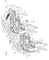
- FIG 1 illustrates a section of a rotary harrow according to the present invention.
- the rotary harrow comprises an elongated box-shaped frame 10 including an elongated channel-shaped profile 12 and an elongated closing plate 14 ( Figure 3 ) fixed to the elongated profile 12 by means of screws 16.
- the elongated channel-shaped profile 12 is formed of a bent steel sheet and comprises a bottom wall 18, two lateral sides 20, and two edges 22.
- the lateral sides 20 are orthogonal to the bottom wall 18 and parallel to each other.
- the edges 22 are formed by ends bent outwardly by 90° from the lateral sides 20.
- the edges 22 are provided with holes 24 in which the screws 16 are engaged for fixing the closing plate 14 to the elongated profile 12
- the bottom wall 18 of the elongated channel-shaped profile 12 is provided with an array of circular openings 26.
- Fixing holes 28 are arranged around each circular opening 26.
- four fixing holes 28 may be provided around each circular opening 26.
- the rotary harrow comprises a plurality of soil working assemblies 30 carried by the elongated channel-shaped profile 12.
- Each soil working assembly 30 is comprised of a support 32 formed by a robust body made of a high resistance metal such as steel or cast iron.
- Each support 32 comprises a hollow portion 34 and a radial flange 36.
- the hollow portion 34 of each support 32 extends partly inside the elongated frame 10 through a respective circular opening 26 of the bottom wall 18.
- the radial flange 36 is located outside the elongated frame 10 and rests on the outer face of the bottom wall 18.
- Each support 32 is fixed to the elongated channel-shaped profile 12 by means of screws 38 which extend through respective fixing holes 28 of the bottom wall 18 and engage respective threaded holes 40 formed in the radial flange 36.
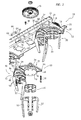
- Each soil working assembly 30 comprises a rotary shaft 42 ( Figure 3 ) which extends through the hollow portion 34 of the respective support 32.
- Each rotary shaft 42 is rotatably supported by two bearings 44 carried by the hollow portion 34 of the support 32.
- Each rotary shaft 42 has one end located inside the elongated frame 10 to which a toothed wheel 46 is fixed, and a head 48 located outside of the elongated frame 10 to which an attachment device 50 is fixed for attaching the teeth 52.
- the attachment device 50 can be, for example, of the type described in the document EP-A-1419682 by the same applicant.
- the toothed wheels 46 of the various soil working assemblies 30 mesh with each other to transmit the rotating movement to the rotary shafts 42 starting from a single transmission box (not illustrated) intended to be connected to the PTO of an agricultural tractor
- the radial flange 36 of each support 32 has at least two extensions 54 which extend in the transverse direction outside of the lateral sides 20 of the elongated profile 12.
- the extensions 54 of each radial flange 36 are fixed to lateral sides 20 opposite to the elongated profile 12.
- each radial flange 36 is essentially rhombus-shaped, with two vertices with an acute angle forming the extensions 54.
- Each extension 54 has a through-hole 56 engaged by a respective fixing screw 58.
- the extensions 54 of the radial flanges 36 are fixed at C-shaped brackets 60 welded on the outer faces of the lateral sides 20 of the elongated profile 12.
- the end of the C-shaped brackets 60 are welded to the sides 20, so that each bracket 60 forms a slot 62 parallel to the respective lateral side 20.
- Each fixing screw 58 engages a respective threaded hole 64 formed in a prismatic block 66 located on the opposite side of the flange 60 relative to the respective extension 54.
- Each prismatic block 66 has two threaded holes 64 which are engaged by the fixing screws 58 of two extensions 54 belonging to two soil working assemblies 30 adjacent to each other.
- the soil working assemblies 30 located at opposite ends of the elongated frame 10 have an extension 54 which is not fixed to a corresponding extension of a working assembly.
- the radial flanges 36 are orientated so that in each adjacent pair of soil working assemblies 30, two extensions 54 belonging to two different soil working assemblies 30 are fixed to the same bracket 60 and to the same prismatic block 66.
- the supports 32 of the soil working assemblies 30 are fixed to the sides 20 of the elongated profile 12 increases the torsional strength of the profile 12, given that the sides 20 contribute to supporting the torsional stresses between the adjacent working assemblies 30.
- a very important additional increase of the strength of the profile 12 is obtained thanks to the fact that the supports 32 of each pair of adjacent working assemblies 30 are fixed to each other.
- the supports 32 interconnected to each other as well as to the frame 10 render the frame 10 more rigid compared to the solutions according to the prior art in which each support transfers the stresses coming from the soil solely to the frame.
- the solution according to the present invention allows avoiding the use of a reinforcing plate that, in the solutions according to the prior art, is welded onto the inner face of the bottom wall of the elongated channel-shaped profile.
- the solution according to the invention also allows reduction of the thickness of the elongated channel-shaped profile from a thickness of 8 mm (used in the solutions according to the prior art) to a thickness of 5-6 mm.
- the solution according to the present invention allows a higher torsional strength to be obtained.
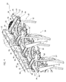
- Figure 4 illustrates a second embodiment of the present invention.
- the elements corresponding to those previously described are indicated with the same reference numerals.
- each radial flange 36 has four extensions 54 fixed pairwise to opposite lateral sides 20 of the elongated profile 12.
- the two extensions 54 of each radial flange 36 located on the same side 20 are fixed to two adjacent brackets 60.
- each radial flange 36 is fixed to a radial flange 36 of an adjacent soil working assembly 30 by means of two extensions 54 located on opposite sides of the frame 18.
Landscapes
- Life Sciences & Earth Sciences (AREA)
- Engineering & Computer Science (AREA)
- Mechanical Engineering (AREA)
- Soil Sciences (AREA)
- Environmental Sciences (AREA)
- Soil Working Implements (AREA)
Applications Claiming Priority (1)
| Application Number | Priority Date | Filing Date | Title |
|---|---|---|---|
| ITTO20140771 | 2014-09-29 |
Publications (2)
| Publication Number | Publication Date |
|---|---|
| EP3000293A1 true EP3000293A1 (de) | 2016-03-30 |
| EP3000293B1 EP3000293B1 (de) | 2018-11-07 |
Family
ID=51982677
Family Applications (1)
| Application Number | Title | Priority Date | Filing Date |
|---|---|---|---|
| EP15186195.2A Active EP3000293B1 (de) | 2014-09-29 | 2015-09-22 | Kreiselegge mit verbesserter festigkeit |
Country Status (1)
| Country | Link |
|---|---|
| EP (1) | EP3000293B1 (de) |
Cited By (1)
| Publication number | Priority date | Publication date | Assignee | Title |
|---|---|---|---|---|
| CN106879267A (zh) * | 2017-03-03 | 2017-06-23 | 河北省农业机械化研究所有限公司 | 一种节能节肥的果园开沟施肥机 |
Citations (4)
| Publication number | Priority date | Publication date | Assignee | Title |
|---|---|---|---|---|
| GB2035026A (en) * | 1978-11-24 | 1980-06-18 | Kuhn Sa | Rotor and rotor arrangement for power harrow |
| FR2559013A1 (fr) * | 1977-12-02 | 1985-08-09 | Patent Concern Nv | Machine de travail du sol |
| EP1419682A1 (de) | 2002-11-12 | 2004-05-19 | Frandent di Ezio Bruno | Werkzeughalter für ein Bodenbearbeitungsgerät und Werkzeug |
| EP2111733A1 (de) * | 2008-04-25 | 2009-10-28 | Amazonen-Werke H. Dreyer GmbH & Co. KG | Bodbenbearbeitungsmaschine |
-
2015
- 2015-09-22 EP EP15186195.2A patent/EP3000293B1/de active Active
Patent Citations (4)
| Publication number | Priority date | Publication date | Assignee | Title |
|---|---|---|---|---|
| FR2559013A1 (fr) * | 1977-12-02 | 1985-08-09 | Patent Concern Nv | Machine de travail du sol |
| GB2035026A (en) * | 1978-11-24 | 1980-06-18 | Kuhn Sa | Rotor and rotor arrangement for power harrow |
| EP1419682A1 (de) | 2002-11-12 | 2004-05-19 | Frandent di Ezio Bruno | Werkzeughalter für ein Bodenbearbeitungsgerät und Werkzeug |
| EP2111733A1 (de) * | 2008-04-25 | 2009-10-28 | Amazonen-Werke H. Dreyer GmbH & Co. KG | Bodbenbearbeitungsmaschine |
Cited By (1)
| Publication number | Priority date | Publication date | Assignee | Title |
|---|---|---|---|---|
| CN106879267A (zh) * | 2017-03-03 | 2017-06-23 | 河北省农业机械化研究所有限公司 | 一种节能节肥的果园开沟施肥机 |
Also Published As
| Publication number | Publication date |
|---|---|
| EP3000293B1 (de) | 2018-11-07 |
Similar Documents
| Publication | Publication Date | Title |
|---|---|---|
| US8074914B2 (en) | Crushing bucket | |
| US9888621B2 (en) | Blade assembly flange | |
| EP3000293B1 (de) | Kreiselegge mit verbesserter festigkeit | |
| AU2023274120B2 (en) | Agricultural tilting bearing assembly and improved support bracket for connecting the same to agricultural equipment | |
| DE102013018709A1 (de) | Gehäuse für ein Getriebe | |
| CN204849878U (zh) | 用于液压锤的锤体的阻尼器系统 | |
| US1829605A (en) | Roller for crushing clods | |
| EP0041341B1 (de) | Rotor für Bodenbearbeitung | |
| JP6405085B2 (ja) | 耕耘爪 | |
| DE102012214996A1 (de) | Fliehkraftpendel mit Axialschwingungsdämpfung | |
| JP6189641B2 (ja) | チェーン駆動用のスプロケット | |
| CN108551776B (zh) | 防卷草转轴及农用耕地除草机 | |
| JP6038723B2 (ja) | ロータリ耕耘機 | |
| JP5782277B2 (ja) | 動力伝達ユニット及び動力伝達機構の取付方法 | |
| JP6745108B2 (ja) | 農作業機 | |
| JP2015139427A (ja) | ロータリ耕耘装置 | |
| JP2013013346A (ja) | 耕耘ロータ | |
| JP5863169B2 (ja) | 農作業機 | |
| JP6151057B2 (ja) | 農作業機 | |
| CN202679915U (zh) | 一种微耕机压草轮 | |
| JP2019030228A (ja) | 農作業機 | |
| JP2015131518A (ja) | ステアリングホイールの位置調節装置 | |
| RU2612089C1 (ru) | Пластинчатая цепь | |
| US20170036713A1 (en) | Frame assembly for machine | |
| JP2020099260A (ja) | 歩行型作業機 |
Legal Events
| Date | Code | Title | Description |
|---|---|---|---|
| PUAI | Public reference made under article 153(3) epc to a published international application that has entered the european phase |
Free format text: ORIGINAL CODE: 0009012 |
|
| AK | Designated contracting states |
Kind code of ref document: A1 Designated state(s): AL AT BE BG CH CY CZ DE DK EE ES FI FR GB GR HR HU IE IS IT LI LT LU LV MC MK MT NL NO PL PT RO RS SE SI SK SM TR |
|
| AX | Request for extension of the european patent |
Extension state: BA ME |
|
| 17P | Request for examination filed |
Effective date: 20160610 |
|
| RBV | Designated contracting states (corrected) |
Designated state(s): AL AT BE BG CH CY CZ DE DK EE ES FI FR GB GR HR HU IE IS IT LI LT LU LV MC MK MT NL NO PL PT RO RS SE SI SK SM TR |
|
| RIC1 | Information provided on ipc code assigned before grant |
Ipc: A01B 33/06 20060101AFI20180618BHEP |
|
| GRAP | Despatch of communication of intention to grant a patent |
Free format text: ORIGINAL CODE: EPIDOSNIGR1 |
|
| STAA | Information on the status of an ep patent application or granted ep patent |
Free format text: STATUS: GRANT OF PATENT IS INTENDED |
|
| INTG | Intention to grant announced |
Effective date: 20180727 |
|
| RIN1 | Information on inventor provided before grant (corrected) |
Inventor name: BRUNO, EZIO |
|
| GRAS | Grant fee paid |
Free format text: ORIGINAL CODE: EPIDOSNIGR3 |
|
| GRAA | (expected) grant |
Free format text: ORIGINAL CODE: 0009210 |
|
| STAA | Information on the status of an ep patent application or granted ep patent |
Free format text: STATUS: THE PATENT HAS BEEN GRANTED |
|
| AK | Designated contracting states |
Kind code of ref document: B1 Designated state(s): AL AT BE BG CH CY CZ DE DK EE ES FI FR GB GR HR HU IE IS IT LI LT LU LV MC MK MT NL NO PL PT RO RS SE SI SK SM TR |
|
| REG | Reference to a national code |
Ref country code: GB Ref legal event code: FG4D |
|
| REG | Reference to a national code |
Ref country code: CH Ref legal event code: EP Ref country code: AT Ref legal event code: REF Ref document number: 1060974 Country of ref document: AT Kind code of ref document: T Effective date: 20181115 |
|
| REG | Reference to a national code |
Ref country code: DE Ref legal event code: R096 Ref document number: 602015019415 Country of ref document: DE |
|
| REG | Reference to a national code |
Ref country code: IE Ref legal event code: FG4D |
|
| REG | Reference to a national code |
Ref country code: NL Ref legal event code: MP Effective date: 20181107 |
|
| REG | Reference to a national code |
Ref country code: LT Ref legal event code: MG4D |
|
| REG | Reference to a national code |
Ref country code: AT Ref legal event code: MK05 Ref document number: 1060974 Country of ref document: AT Kind code of ref document: T Effective date: 20181107 |
|
| PG25 | Lapsed in a contracting state [announced via postgrant information from national office to epo] |
Ref country code: FI Free format text: LAPSE BECAUSE OF FAILURE TO SUBMIT A TRANSLATION OF THE DESCRIPTION OR TO PAY THE FEE WITHIN THE PRESCRIBED TIME-LIMIT Effective date: 20181107 Ref country code: IS Free format text: LAPSE BECAUSE OF FAILURE TO SUBMIT A TRANSLATION OF THE DESCRIPTION OR TO PAY THE FEE WITHIN THE PRESCRIBED TIME-LIMIT Effective date: 20190307 Ref country code: LT Free format text: LAPSE BECAUSE OF FAILURE TO SUBMIT A TRANSLATION OF THE DESCRIPTION OR TO PAY THE FEE WITHIN THE PRESCRIBED TIME-LIMIT Effective date: 20181107 Ref country code: BG Free format text: LAPSE BECAUSE OF FAILURE TO SUBMIT A TRANSLATION OF THE DESCRIPTION OR TO PAY THE FEE WITHIN THE PRESCRIBED TIME-LIMIT Effective date: 20190207 Ref country code: HR Free format text: LAPSE BECAUSE OF FAILURE TO SUBMIT A TRANSLATION OF THE DESCRIPTION OR TO PAY THE FEE WITHIN THE PRESCRIBED TIME-LIMIT Effective date: 20181107 Ref country code: ES Free format text: LAPSE BECAUSE OF FAILURE TO SUBMIT A TRANSLATION OF THE DESCRIPTION OR TO PAY THE FEE WITHIN THE PRESCRIBED TIME-LIMIT Effective date: 20181107 Ref country code: LV Free format text: LAPSE BECAUSE OF FAILURE TO SUBMIT A TRANSLATION OF THE DESCRIPTION OR TO PAY THE FEE WITHIN THE PRESCRIBED TIME-LIMIT Effective date: 20181107 Ref country code: NO Free format text: LAPSE BECAUSE OF FAILURE TO SUBMIT A TRANSLATION OF THE DESCRIPTION OR TO PAY THE FEE WITHIN THE PRESCRIBED TIME-LIMIT Effective date: 20190207 Ref country code: AT Free format text: LAPSE BECAUSE OF FAILURE TO SUBMIT A TRANSLATION OF THE DESCRIPTION OR TO PAY THE FEE WITHIN THE PRESCRIBED TIME-LIMIT Effective date: 20181107 |
|
| PG25 | Lapsed in a contracting state [announced via postgrant information from national office to epo] |
Ref country code: PT Free format text: LAPSE BECAUSE OF FAILURE TO SUBMIT A TRANSLATION OF THE DESCRIPTION OR TO PAY THE FEE WITHIN THE PRESCRIBED TIME-LIMIT Effective date: 20190307 Ref country code: AL Free format text: LAPSE BECAUSE OF FAILURE TO SUBMIT A TRANSLATION OF THE DESCRIPTION OR TO PAY THE FEE WITHIN THE PRESCRIBED TIME-LIMIT Effective date: 20181107 Ref country code: GR Free format text: LAPSE BECAUSE OF FAILURE TO SUBMIT A TRANSLATION OF THE DESCRIPTION OR TO PAY THE FEE WITHIN THE PRESCRIBED TIME-LIMIT Effective date: 20190208 Ref country code: RS Free format text: LAPSE BECAUSE OF FAILURE TO SUBMIT A TRANSLATION OF THE DESCRIPTION OR TO PAY THE FEE WITHIN THE PRESCRIBED TIME-LIMIT Effective date: 20181107 Ref country code: SE Free format text: LAPSE BECAUSE OF FAILURE TO SUBMIT A TRANSLATION OF THE DESCRIPTION OR TO PAY THE FEE WITHIN THE PRESCRIBED TIME-LIMIT Effective date: 20181107 Ref country code: NL Free format text: LAPSE BECAUSE OF FAILURE TO SUBMIT A TRANSLATION OF THE DESCRIPTION OR TO PAY THE FEE WITHIN THE PRESCRIBED TIME-LIMIT Effective date: 20181107 |
|
| PG25 | Lapsed in a contracting state [announced via postgrant information from national office to epo] |
Ref country code: CZ Free format text: LAPSE BECAUSE OF FAILURE TO SUBMIT A TRANSLATION OF THE DESCRIPTION OR TO PAY THE FEE WITHIN THE PRESCRIBED TIME-LIMIT Effective date: 20181107 Ref country code: DK Free format text: LAPSE BECAUSE OF FAILURE TO SUBMIT A TRANSLATION OF THE DESCRIPTION OR TO PAY THE FEE WITHIN THE PRESCRIBED TIME-LIMIT Effective date: 20181107 Ref country code: IT Free format text: LAPSE BECAUSE OF FAILURE TO SUBMIT A TRANSLATION OF THE DESCRIPTION OR TO PAY THE FEE WITHIN THE PRESCRIBED TIME-LIMIT Effective date: 20181107 Ref country code: PL Free format text: LAPSE BECAUSE OF FAILURE TO SUBMIT A TRANSLATION OF THE DESCRIPTION OR TO PAY THE FEE WITHIN THE PRESCRIBED TIME-LIMIT Effective date: 20181107 |
|
| REG | Reference to a national code |
Ref country code: DE Ref legal event code: R097 Ref document number: 602015019415 Country of ref document: DE |
|
| PG25 | Lapsed in a contracting state [announced via postgrant information from national office to epo] |
Ref country code: SK Free format text: LAPSE BECAUSE OF FAILURE TO SUBMIT A TRANSLATION OF THE DESCRIPTION OR TO PAY THE FEE WITHIN THE PRESCRIBED TIME-LIMIT Effective date: 20181107 Ref country code: RO Free format text: LAPSE BECAUSE OF FAILURE TO SUBMIT A TRANSLATION OF THE DESCRIPTION OR TO PAY THE FEE WITHIN THE PRESCRIBED TIME-LIMIT Effective date: 20181107 Ref country code: EE Free format text: LAPSE BECAUSE OF FAILURE TO SUBMIT A TRANSLATION OF THE DESCRIPTION OR TO PAY THE FEE WITHIN THE PRESCRIBED TIME-LIMIT Effective date: 20181107 Ref country code: SM Free format text: LAPSE BECAUSE OF FAILURE TO SUBMIT A TRANSLATION OF THE DESCRIPTION OR TO PAY THE FEE WITHIN THE PRESCRIBED TIME-LIMIT Effective date: 20181107 |
|
| PLBE | No opposition filed within time limit |
Free format text: ORIGINAL CODE: 0009261 |
|
| STAA | Information on the status of an ep patent application or granted ep patent |
Free format text: STATUS: NO OPPOSITION FILED WITHIN TIME LIMIT |
|
| 26N | No opposition filed |
Effective date: 20190808 |
|
| PG25 | Lapsed in a contracting state [announced via postgrant information from national office to epo] |
Ref country code: SI Free format text: LAPSE BECAUSE OF FAILURE TO SUBMIT A TRANSLATION OF THE DESCRIPTION OR TO PAY THE FEE WITHIN THE PRESCRIBED TIME-LIMIT Effective date: 20181107 |
|
| PG25 | Lapsed in a contracting state [announced via postgrant information from national office to epo] |
Ref country code: TR Free format text: LAPSE BECAUSE OF FAILURE TO SUBMIT A TRANSLATION OF THE DESCRIPTION OR TO PAY THE FEE WITHIN THE PRESCRIBED TIME-LIMIT Effective date: 20181107 |
|
| REG | Reference to a national code |
Ref country code: DE Ref legal event code: R119 Ref document number: 602015019415 Country of ref document: DE |
|
| PG25 | Lapsed in a contracting state [announced via postgrant information from national office to epo] |
Ref country code: MC Free format text: LAPSE BECAUSE OF FAILURE TO SUBMIT A TRANSLATION OF THE DESCRIPTION OR TO PAY THE FEE WITHIN THE PRESCRIBED TIME-LIMIT Effective date: 20181107 |
|
| REG | Reference to a national code |
Ref country code: CH Ref legal event code: PL |
|
| PG25 | Lapsed in a contracting state [announced via postgrant information from national office to epo] |
Ref country code: IE Free format text: LAPSE BECAUSE OF NON-PAYMENT OF DUE FEES Effective date: 20190922 Ref country code: CH Free format text: LAPSE BECAUSE OF NON-PAYMENT OF DUE FEES Effective date: 20190930 Ref country code: DE Free format text: LAPSE BECAUSE OF NON-PAYMENT OF DUE FEES Effective date: 20200401 Ref country code: LI Free format text: LAPSE BECAUSE OF NON-PAYMENT OF DUE FEES Effective date: 20190930 Ref country code: LU Free format text: LAPSE BECAUSE OF NON-PAYMENT OF DUE FEES Effective date: 20190922 |
|
| REG | Reference to a national code |
Ref country code: BE Ref legal event code: MM Effective date: 20190930 |
|
| PG25 | Lapsed in a contracting state [announced via postgrant information from national office to epo] |
Ref country code: BE Free format text: LAPSE BECAUSE OF NON-PAYMENT OF DUE FEES Effective date: 20190930 |
|
| GBPC | Gb: european patent ceased through non-payment of renewal fee |
Effective date: 20190922 |
|
| PG25 | Lapsed in a contracting state [announced via postgrant information from national office to epo] |
Ref country code: GB Free format text: LAPSE BECAUSE OF NON-PAYMENT OF DUE FEES Effective date: 20190922 |
|
| PG25 | Lapsed in a contracting state [announced via postgrant information from national office to epo] |
Ref country code: CY Free format text: LAPSE BECAUSE OF FAILURE TO SUBMIT A TRANSLATION OF THE DESCRIPTION OR TO PAY THE FEE WITHIN THE PRESCRIBED TIME-LIMIT Effective date: 20181107 |
|
| PG25 | Lapsed in a contracting state [announced via postgrant information from national office to epo] |
Ref country code: HU Free format text: LAPSE BECAUSE OF FAILURE TO SUBMIT A TRANSLATION OF THE DESCRIPTION OR TO PAY THE FEE WITHIN THE PRESCRIBED TIME-LIMIT; INVALID AB INITIO Effective date: 20150922 Ref country code: MT Free format text: LAPSE BECAUSE OF FAILURE TO SUBMIT A TRANSLATION OF THE DESCRIPTION OR TO PAY THE FEE WITHIN THE PRESCRIBED TIME-LIMIT Effective date: 20181107 |
|
| PG25 | Lapsed in a contracting state [announced via postgrant information from national office to epo] |
Ref country code: MK Free format text: LAPSE BECAUSE OF FAILURE TO SUBMIT A TRANSLATION OF THE DESCRIPTION OR TO PAY THE FEE WITHIN THE PRESCRIBED TIME-LIMIT Effective date: 20181107 |
|
| PGFP | Annual fee paid to national office [announced via postgrant information from national office to epo] |
Ref country code: FR Payment date: 20240925 Year of fee payment: 10 |