EP3000000B1 - Système et procédé de reconnaissance de déformations - Google Patents
Système et procédé de reconnaissance de déformations Download PDFInfo
- Publication number
- EP3000000B1 EP3000000B1 EP14735465.8A EP14735465A EP3000000B1 EP 3000000 B1 EP3000000 B1 EP 3000000B1 EP 14735465 A EP14735465 A EP 14735465A EP 3000000 B1 EP3000000 B1 EP 3000000B1
- Authority
- EP
- European Patent Office
- Prior art keywords
- bulge
- transformation
- metal part
- sheet
- dimensional model
- Prior art date
- Legal status (The legal status is an assumption and is not a legal conclusion. Google has not performed a legal analysis and makes no representation as to the accuracy of the status listed.)
- Active
Links
Images


Classifications
-
- G—PHYSICS
- G05—CONTROLLING; REGULATING
- G05B—CONTROL OR REGULATING SYSTEMS IN GENERAL; FUNCTIONAL ELEMENTS OF SUCH SYSTEMS; MONITORING OR TESTING ARRANGEMENTS FOR SUCH SYSTEMS OR ELEMENTS
- G05B19/00—Program-control systems
- G05B19/02—Program-control systems electric
- G05B19/18—Numerical control [NC], i.e. automatically operating machines, in particular machine tools, e.g. in a manufacturing environment, so as to execute positioning, movement or co-ordinated operations by means of program data in numerical form
- G05B19/4097—Numerical control [NC], i.e. automatically operating machines, in particular machine tools, e.g. in a manufacturing environment, so as to execute positioning, movement or co-ordinated operations by means of program data in numerical form characterised by using design data to control NC machines, e.g. CAD/CAM
-
- G—PHYSICS
- G05—CONTROLLING; REGULATING
- G05B—CONTROL OR REGULATING SYSTEMS IN GENERAL; FUNCTIONAL ELEMENTS OF SUCH SYSTEMS; MONITORING OR TESTING ARRANGEMENTS FOR SUCH SYSTEMS OR ELEMENTS
- G05B19/00—Program-control systems
- G05B19/02—Program-control systems electric
- G05B19/18—Numerical control [NC], i.e. automatically operating machines, in particular machine tools, e.g. in a manufacturing environment, so as to execute positioning, movement or co-ordinated operations by means of program data in numerical form
- G05B19/4093—Numerical control [NC], i.e. automatically operating machines, in particular machine tools, e.g. in a manufacturing environment, so as to execute positioning, movement or co-ordinated operations by means of program data in numerical form characterised by part programming, e.g. entry of geometrical information as taken from a technical drawing, combining this with machining and material information to obtain control information, named part program, for the NC machine
- G05B19/40937—Numerical control [NC], i.e. automatically operating machines, in particular machine tools, e.g. in a manufacturing environment, so as to execute positioning, movement or co-ordinated operations by means of program data in numerical form characterised by part programming, e.g. entry of geometrical information as taken from a technical drawing, combining this with machining and material information to obtain control information, named part program, for the NC machine concerning programming of machining or material parameters, pocket machining
- G05B19/40938—Tool management
-
- G—PHYSICS
- G06—COMPUTING OR CALCULATING; COUNTING
- G06F—ELECTRIC DIGITAL DATA PROCESSING
- G06F17/00—Digital computing or data processing equipment or methods, specially adapted for specific functions
- G06F17/10—Complex mathematical operations
- G06F17/14—Fourier, Walsh or analogous domain transformations, e.g. Laplace, Hilbert, Karhunen-Loeve, transforms
- G06F17/141—Discrete Fourier transforms
-
- G—PHYSICS
- G05—CONTROLLING; REGULATING
- G05B—CONTROL OR REGULATING SYSTEMS IN GENERAL; FUNCTIONAL ELEMENTS OF SUCH SYSTEMS; MONITORING OR TESTING ARRANGEMENTS FOR SUCH SYSTEMS OR ELEMENTS
- G05B2219/00—Program-control systems
- G05B2219/30—Nc systems
- G05B2219/35—Nc in input of data, input till input file format
- G05B2219/35012—Cad cam
-
- G—PHYSICS
- G05—CONTROLLING; REGULATING
- G05B—CONTROL OR REGULATING SYSTEMS IN GENERAL; FUNCTIONAL ELEMENTS OF SUCH SYSTEMS; MONITORING OR TESTING ARRANGEMENTS FOR SUCH SYSTEMS OR ELEMENTS
- G05B2219/00—Program-control systems
- G05B2219/30—Nc systems
- G05B2219/35—Nc in input of data, input till input file format
- G05B2219/35194—From workpiece data derive tool data
-
- G—PHYSICS
- G05—CONTROLLING; REGULATING
- G05B—CONTROL OR REGULATING SYSTEMS IN GENERAL; FUNCTIONAL ELEMENTS OF SUCH SYSTEMS; MONITORING OR TESTING ARRANGEMENTS FOR SUCH SYSTEMS OR ELEMENTS
- G05B2219/00—Program-control systems
- G05B2219/30—Nc systems
- G05B2219/36—Nc in input of data, input key till input tape
- G05B2219/36278—Topological classification of forming, machining process
-
- G—PHYSICS
- G05—CONTROLLING; REGULATING
- G05B—CONTROL OR REGULATING SYSTEMS IN GENERAL; FUNCTIONAL ELEMENTS OF SUCH SYSTEMS; MONITORING OR TESTING ARRANGEMENTS FOR SUCH SYSTEMS OR ELEMENTS
- G05B2219/00—Program-control systems
- G05B2219/30—Nc systems
- G05B2219/36—Nc in input of data, input key till input tape
- G05B2219/36352—Select tool as function of part shape, number of grooves and groove width
-
- Y—GENERAL TAGGING OF NEW TECHNOLOGICAL DEVELOPMENTS; GENERAL TAGGING OF CROSS-SECTIONAL TECHNOLOGIES SPANNING OVER SEVERAL SECTIONS OF THE IPC; TECHNICAL SUBJECTS COVERED BY FORMER USPC CROSS-REFERENCE ART COLLECTIONS [XRACs] AND DIGESTS
- Y02—TECHNOLOGIES OR APPLICATIONS FOR MITIGATION OR ADAPTATION AGAINST CLIMATE CHANGE
- Y02P—CLIMATE CHANGE MITIGATION TECHNOLOGIES IN THE PRODUCTION OR PROCESSING OF GOODS
- Y02P90/00—Enabling technologies with a potential contribution to greenhouse gas [GHG] emissions mitigation
- Y02P90/02—Total factory control, e.g. smart factories, flexible manufacturing systems [FMS] or integrated manufacturing systems [IMS]
Definitions
- the invention relates to a system and a method for automatically detecting three-dimensional transformations in a three-dimensional model of a sheet metal part.
- the aforementioned transformations, such as cups or beads, can in practice, for example, by a machine 10, which in Fig. 1 is shown, are introduced into the sheet metal part.
- the machine 10 here comprises a two-part forming tool 11a, 11b which is accommodated in a housing 12 of the machine 10.
- the sheet metal part (not shown in the figure) is passed between the upper and lower forming tools 11a, 11b, wherein the forming tools 11a, 11b engage the sheet metal part, so that a bulge forming the forming is produced.
- the machine 10 further comprises a processor 13 for the automatic control of the necessary method steps through the individual machine parts based on electronic data.
- pairs of forming tools 11a, 11b shown in machine 10 of FIG Fig. 1 can be used.
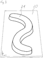
- FIG. 3 A three-dimensional representation of a sheet metal part 20 with bulge 21 produced in this way is shown in the perspective view of FIG Fig. 3 shown.
- the corresponding CAM device (such as the one described in US Pat Fig. 1 shown machine 10 or an external computer) are fed a model.
- This is conventionally derived from a three-dimensional model generated by a computer aided design (CAD) method.
- CAD computer aided design
- it must be determined which tool is to be used for generating the three-dimensional forming.
- this information must be determined manually and, if necessary, fed into a CAM device, which is both time-consuming and labor-intensive.
- the invention is therefore based on the object of specifying a system and a method for the automatic recognition of three-dimensional transformations in a three-dimensional model of a sheet metal part, by means of which an automatic assignment of a tool generating the forming can be determined from a three-dimensional model of the sheet metal part with a forming.
- the first section of section S2 and the second section of section S4 can extend in particular perpendicular to the plane spanned by the first direction X and the second direction Y level. This enables a particularly accurate reproduction of the tool type.
- first cutting section S2 and the second cutting section S4 may extend at respective positions in the first direction X and the second direction Y at which the bulge starts or ends.
- the cut sections S2 and S4 close directly to the bulge, whereby the outline of the bulge is reproduced particularly accurately, which increases the security of the assignment to a corresponding tool type.
- the computer unit is designed to produce a further vertical section, which is different from the said vertical section, and to subject the further vertical cross-sectional contour of the recess resulting from the further vertical section to a Fourier transformation in order to obtain a specific vertical section Fourier coefficients of the further vertical cross-sectional outline to determine.
- This embodiment offers the possibility of obtaining a clear assignment to a tool type through the further vertical cut, if such a clear assignment by the first vertical cut was not possible.
- the Fourier coefficient of the first vertical section may be discarded and only the Fourier coefficient of the further vertical section may be used for the assignment.
- an assignment can be made via two or more vertical sections become.
- the inventive system may further comprise a display unit and the computer unit may be configured to request a manual input of tool data via the display unit if no corresponding tool data is stored in the memory unit for the determined Fourier coefficients. In this way it is possible to complete the assignment table and to integrate new tool types.
- the computer unit can moreover be designed to generate from the data of the three-dimensional model of the sheet metal part a two-dimensional model of the sheet metal part in the plane spanned by the first direction X and the second direction Y and to integrate into the two-dimensional model the determined or input tool data ,
- a data record can be generated which contains in particular all information necessary for use in a CAM device in compressed form. This data can be used by the CAM device directly to control a CAM process for the automated production of a sheet metal part with a corresponding bulge.
- the computer unit is designed to use the determined or input tool data as a text module in the two-dimensional model of the Sheet metal part to integrate.
- This embodiment is particularly suitable for the pictorial reproduction of a model of a piece of sheet metal with bulge, since here the tool type can also be detected directly visually by a user.
- the input unit may be further configured to input tool data for storage in the allocation table of the storage unit. In this way, the assignment table can be supplemented manually or automatically or adapted to new tool types.
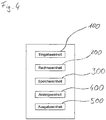
- a system for the automatic detection of three-dimensional transformations on in a three-dimensional model of a sheet metal part.
- a system according to a first embodiment of the invention comprises an input unit 100, for example an interface for data transmission or a user interface of mouse and keyboard, for the manual or automatic input of data of a three-dimensional model of a sheet metal part, a computer unit 200, which comprises a processor and is designed to carry out the method steps necessary for recognizing the transformations, a memory unit 300 for storing an allocation table, and optionally a display unit 400, eg a monitor, for communication with a user and an output unit 500 Input unit 100, the memory unit 300, the display unit 400 and the output unit 500 are functionally connected to the computer unit 200.
- an input unit 100 for example an interface for data transmission or a user interface of mouse and keyboard
- a computer unit 200 which comprises a processor and is designed to carry out the method steps necessary for recognizing the transformations
- a memory unit 300 for storing an allocation table
- a display unit 400
- Fig. 5 represents a perspective view of the sheet metal part 20 with the bulge 21 of Fig. 3 as a three-dimensional model, as it is produced for example in the context of a CAD method.
- the sheet metal part 20 of the three-dimensional model extends in a plane defined by a first direction X and a second direction Y, the protrusion 21 being formed in a direction Z, so that the sheet metal part 20 with the protrusion 21 overall forms a three-dimensional unit.
- Fig. 5 are additionally shown two cutting planes, namely a horizontal sectional plane H parallel to the plane spanned by the first and the second direction X, Y and a vertical sectional plane V perpendicular to the plane spanned by the first and the second direction X, Y level.
- first of all a horizontal section along the horizontal sectional plane H and a vertical section along the vertical sectional plane V are executed by the three-dimensional model.
- the layers of the horizontal sectional plane H and the vertical sectional plane V drawn in the figure are given by way of example only. They can also be applied at other locations of the bulge 21, as long as they each intersect the bulge 21.
- the horizontal section and the vertical section a horizontal or a vertical cross-sectional outline of the bulge 21 are generated, which form in the embodiment shown in each case a closed contour.
- the horizontal section preferably runs between a highest point 21a of the bulge 21 in the Z direction and the side of the sheet metal piece 20 which is closest to the highest point 21a in the Z direction.
- the said side of the sheet metal piece 20 is an upper side 20a, which in the context of the invention is defined as being the side on which the convexity of the bulge is formed.
- the "highest point" 21a in the present case as can be seen from the figure, a flat planar area, which forms the upper end of the bulge 21, in other words the top.
- the horizontal cut can be made to be only slightly below the highest point 21a, i. only slightly below the top of the bulge 21 extends.
- lightly in the context of the invention, for example, a distance of a few microns to a few mm to understand.
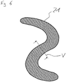
- the vertical section may be set at various positions along the extending direction of the protrusion 21, but it is preferably made perpendicular to the current direction at the interface (the extending direction is in FIG Fig. 6 indicated by arrows).
- Fig. 6 is shown in plan view, the closed horizontal cross-sectional outline, which results from the horizontal section described above. Since the horizontal section in the present case only slightly below the top of the bulge 21, the area corresponds within the cross-sectional contour shown, approximately the area of the top of the bulge 21 as shown in FIG Fig. 5 is shown. Through the line V through the cross-sectional outline of Fig. 6 the vertical section is indicated, which the in Fig. 7 shown view results.
- Fig. 5 Does not have the bulge as in Fig. 5 shown a shape with a route, for example, the in Fig. 5 shown S-shape with two end points, but a closed shape, such as a ring, resulting from the horizontal cut not a closed contour, but two, in this case circular contours, namely the inner circle contour and the outer circle contour of the circular bulge.
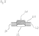
- the vertical section leads perpendicular to the plane spanned by the first direction X and the second direction Y also to a closed cross-sectional outline, which is composed of a series of several sections, namely a convex section S1, a first section of section S2 , a concave section S3 and a second section section S4.
- the convex section S1 extends from the top of the sheet metal piece 20 here obliquely upwards in the Z direction, then passes into a flat part, which here runs parallel to the top of the sheet metal piece 20, and extends laterally obliquely down to in turn to the top of the sheet metal piece 20.
- the adjoining cutting section line S2 extends here in the Z direction vertically downwards from the top of the sheet metal piece 20 to an opposite bottom thereof.
- the concave subsection S3 is here again from an obliquely upwardly extending part, an adjoining approximately parallel to the top of the sheet metal piece 20th and an obliquely downwardly extending portion composed.
- the cross-sectional contour is finally closed by the section section S4, which extends here substantially perpendicularly between the underside of the sheet metal piece 20 and the top thereof.
- two closed cross-sectional contours are obtained by the two sections, which represent a closed polygon.
- a closed polygon can be subjected to a Fourier transformation, by means of which a Fourier coefficient F1, F2 is obtained for each closed polygon.
- the method of Fourier transformation is well known to those skilled in the computer-aided design art, such as Bronstein, Semendjajew, Taschenbuch der Mathematik, and will therefore not be discussed further here.
- a corresponding allocation table which links different Fourier coefficients F1, F2 with corresponding tool data, can be found in the in Fig. 4 be shown stored memory unit 300.
- the tool data can then be output via the output unit 500 of FIG Fig. 4 issued and one example CAM device, as in Fig. 1 shown is supplied.
- the convex part S1 generally represents the part which extends between respective positions in the first direction X and the second direction Y, where the bulge starts and ends, above the top of the sheet piece 20.
- the concave subsection S3 generally represents that subsection which extends between respective positions in the first direction X and the second direction Y, at which the bulge begins or ends, above the underside of the sheet metal piece 20.
- a horizontal section through the bulge of the model is calculated.
- a plane parallel to the direction X and to the direction Y is used to determine their sectional area with the bulge.
- a plane perpendicular to the plane spanned by X direction and Y direction is used to obtain a cross-sectional area of the sheet piece.
- the orientation of the plane is preferably carried out here so that it is perpendicular to the longitudinal course of the bulge.
- the cross-sectional area is limited where it stands out from the sheet metal part. It is there where the bulge deviates for the first time in the direction Z from the base of the sheet metal part, the cross-sectional area perpendicular to the sheet metal of the sheet metal part limited.
- a step St4 the closed cross-sectional contours obtained by the cuts are Fourier-transformed to obtain Fourier coefficients of the cross-sectional contours. For a bulge having a variable extent in the Z direction, it may be necessary to calculate two or more vertical cuts and corresponding coefficients to uniquely determine a tool.
- the Fourier coefficients thus obtained are assigned in a next step St5 tool data of a tool type, for example using a predefined assignment table. For this purpose, coefficients moving in certain tolerance ranges are searched in the table, and tool information stored for corresponding coefficients, for example an identification number of the tool, is read out. If no corresponding tool information is available for the coefficients, the user is requested to enter corresponding information. In this case, the entered information is permanently stored in the allocation table and is also available for later use cases.
- step St6 the output of the tool data of the tool type determined in this way takes place.
- control components of the computer unit may optionally be replaced by the use of a dongle, i. a device that is not replicable and whose presence is required and queried by the in-house control components to be secured against unauthorized entry of data.
- a dongle i. a device that is not replicable and whose presence is required and queried by the in-house control components to be secured against unauthorized entry of data.
- the invention is not limited to determining the coefficients for the association between the bulge to be formed and the tool by Fourier transformation. Although this is advantageous since the center of gravity of the tool can be determined from the hereby determined Fourier coefficients. The latter is helpful for the positioning of the tool to the workpiece.
- other transformations in particular integral transformations, for example the Laplace transform, can be used to determine the coefficients.
- junctors ... "and”, “or” and “either ... or” are used in the meaning that is based on the logical conjunction, the logical adjunct (often “and / or"), or the logical contravalence are.
- system comprises a display unit (400) and the computer unit (200) is adapted to request a manual input of tool data via the display unit (400) if for the determined Fourier coefficients no corresponding tool data in the memory unit (300) are stored.
- the computer unit (300) is designed to integrate the determined or entered tool data as a text module in the two-dimensional model of the sheet metal part (20).
- the input unit (100) is further configured to input tool data for storage in the allocation table of the storage unit (300).
Landscapes
- Engineering & Computer Science (AREA)
- Physics & Mathematics (AREA)
- General Physics & Mathematics (AREA)
- Manufacturing & Machinery (AREA)
- Mathematical Physics (AREA)
- Automation & Control Theory (AREA)
- Human Computer Interaction (AREA)
- Mathematical Analysis (AREA)
- Computational Mathematics (AREA)
- Pure & Applied Mathematics (AREA)
- Data Mining & Analysis (AREA)
- Mathematical Optimization (AREA)
- Theoretical Computer Science (AREA)
- Geometry (AREA)
- General Engineering & Computer Science (AREA)
- Software Systems (AREA)
- Databases & Information Systems (AREA)
- Algebra (AREA)
- Discrete Mathematics (AREA)
- Numerical Control (AREA)
- Punching Or Piercing (AREA)
Claims (16)
- Système permettant de reconnaître automatiquement des déformations tridimensionnelles dans un modèle tridimensionnel d'une pièce en tôle (20) comprenant :une unité d'entrée (100) pour permettre d'introduire des données d'un modèle tridimensionnel d'une pièce en tôle (20) qui s'étend dans un plan défini par une première direction X et une seconde direction Y, la pièce de tôle (20) comprenant un emboutissage (21) dans une troisième direction Z perpendiculaire au plan défini par la première direction X et la seconde direction Y,une unité de calcul (200) réalisée,pour permettre de créer une coupe horizontale avec le modèle tridimensionnel au travers de l'emboutissage (21) parallèlement au plan défini par la première direction X et la seconde direction Y pour permettre d'obtenir au moins un contour de section horizontale bidimensionnel fermé de l'emboutissage (21),ainsi que pour permettre de créer au moins une coupe verticale perpendiculaire au plan de la pièce en tôle (20) défini par la première direction X et la seconde direction Z pour permettre d'obtenir respectivement un contour de section verticale bidimensionnel fermé de l'emboutissage (21) pour chaque coupe verticale, qui est composée de l'assemblage,- d'un segment partiel convexe (S1),- d'un premier segment partiel de coupe (S2),- d'un segment partiel concave (S3), et- d'un second segment partiel de coupe (S4),- le premier segment partiel de coupe (S2) et le second segment partiel de coupe (S4) s'étendant respectivement entre une première face de la tôle (20) et la seconde face de celle-ci opposée à la première face, et- l'unité de calcul (200) étant en outre réalisée pour permettre de soumettre le contour de section horizontale et le contour de section verticale a une transformation pour déterminer des coefficients de transformation spécifique (F1, F2) du contour de section horizontale et du contour de section verticale,- au moins une unité de mémoire (300) dans laquelle est enregistré un tableau d'association qui associe des données d'outil aux coefficients de transformation (F1, F2), les données d'outil indiquant un type d'outil et l'unité de calcul (200) pouvant accéder à l'unité de mémoire pour déterminer les données d'outil par l'intermédiaire des coefficients de transformation déterminés, et- au moins une unité de sortie pour fournir en sortie les données du modèle tridimensionnel avec les données d'outil.
- Système conforme à la revendication 1,
dans lequel la transformation est une transformation de Fourier, en particulier une transformation de Fourier discrète et les coefficients de transformation sont des coefficients de Fourier. - Système conforme à l'une des revendications 1 et 2, dans lequel l'unité de calcul (200) est conçue de manière à permettre d'obtenir par l'intermédiaire de la coupe horizontale deux contours de section horizontale bidimensionnels fermés de l'emboutissage (21), et
pour permettre de soumettre le premier contour de section horizontale et le second contour de section horizontale à la transformation pour permettre d'obtenir des coefficients de transformation spécifiques. - Système conforme à l'une des revendications 1 à 3,
dans lequel le premier segment partiel de coupe (S2) et le second segment partiel de coupe (S4) s'étendent perpendiculairement au plan défini par la première direction X et la seconde direction Y. - Système conforme à l'une des revendications 1 à 4,
dans lequel le premier segment partiel de coupe (S2) et le second segment partiel de coupe (S4) s'étendent respectivement dans la première direction X et dans la seconde direction Y dans des positions pour lesquelles l'emboutissage commence ou se termine. - Système conforme à l'une des revendications 1 à 5,
dans lequel l'unité de calcul (200) est conçue pour permettre de créer une autre coupe verticale qui est différente de la coupe verticale susmentionnée, et de soumettre l'autre contour de section verticale de l'emboutissage (21) résultant de l'autre coupe verticale à une transformation de Fourier pour déterminer un coefficient de Fourier spécifique (F3) de l'autre contour de section verticale. - Système conforme à l'une des revendications 1 à 6,
dans lequel l'unité de calcul (300) est conçue pour permettre de créer, à partir des données du modèle tridimensionnel de la pièce en tôle (20), un modèle bidimensionnel de cette pièce en tôle (20) dans le plan défini par la première direction X et la seconde direction Y et d'intégrer dans ce modèle bidimensionnel les données d'outil déterminées ou introduites. - Système conforme à l'une des revendications précédentes, dans lequel la coupe horizontale est effectuée à une hauteur dans la troisième direction Z qui est située entre le point le plus haut de l'emboutissage (21) et la face de la pièce en tôle (20) sur laquelle est formé la convexité de l'emboutissage.
- Procédé permettant de reconnaitre automatiquement des déformations tridimensionnelle dans un modèle tridimensionnel d'une pièce en tôle (20) comprenant les étapes suivantes consistant à :détecter des données d'un modèle tridimensionnel d'une pièce en tôle (20) qui s'étend dans un plan défini par une première direction X et une seconde direction Y, cette pièce en tôle (20) ayant un emboutissage (21) dans une troisième direction Z qui est perpendiculaire au plan défini par la première direction X et la seconde direction Y,créer une coupe horizontale avec le modèle tridimensionnel au travers de l'emboutissage (21) parallèlement au plan défini par la première direction X et la seconde direction Y pour obtenir au moins un contour de section horizontale bidimensionnel fermé de l'emboutissage (21), et créer au moins une coupe verticale perpendiculaire au plan de la pièce en tôle (20) défini par la première direction X et la seconde direction Y pour permettre d'obtenir respectivement pour chaque coupe verticale un contour de section verticale bidimensionnel fermé de l'emboutissage (21), qui est constituée par l'assemblage,- d'un segment partiel convexe (S1),- d'un premier segment partiel de coupe (S2),- d'un segment partiel concave (S3), et- d'un second segment partiel de coupe (S4),le premier segment partiel de coupe (S2) et le second segment partiel de coupe (S4) s'étendant respectivement entre une première face de la tôle (20) et la seconde face de celle-ci située à l'opposé de cette première face,- utiliser une transformation sur le contour de section horizontale et le contour de section verticale pour déterminer des coefficients de Fourier spécifiques (F1, F2) du contour de section horizontale et du contour de section verticale,- enregistrer un tableau d'association qui associe des données d'outil aux coefficients de Fourier (F1, F2), les données d'outil indiquant un type d'outil, et- délivrer en sortie les données du modèle tridimensionnel avec les données d'outil.
- Procédé conforme à la revendication 9,
selon lequel la transformation est une transformation de Fourier, en particulier une transformation de Fourier discrète et les coefficients de transformation sont des coefficients de Fourier. - Procédé conforme à l'une des revendications 9 et 10,
selon lequel :lors de l'étape consistant à créer la coupe horizontale, on obtient deux contours de section horizontale bidimensionnels fermés de l'emboutissage (21), etlors de l'étape consistant à utiliser la transformation, on utilise la transformation du premier contour de section horizontale et du second contour de section horizontale pour obtenir des coefficients de transformation spécifique pour le premier contour de section horizontale et également pour le second contour de section horizontale. - Procédé conforme à l'une des revendications 9 à 11,
selon lequel lors de la création de la coupe verticale, le premier segment partiel de coupe (S2) et le second segment partiel de coupe (S4) s'étendent perpendiculairement au plan défini par la première direction X et par la seconde direction Y. - Procédé conforme à l'une des revendications 9 à 12,
selon lequel lors de l'étape consistant à créer la coupe verticale, le premier segment partiel de coupe (S2) et le second segment partiel de coupe (S4) s'étendent respectivement dans la première direction X et dans la seconde direction Y dans des positions pour lesquelles l'emboutissage commence ou se termine. - Procédé conforme à l'une des revendications 9 à 13,
comprenant en outre des étapes consistant à :créer une autre coupe verticale qui est différente de la coupe verticale susmentionnée, etutiliser une transformation de Fourier sur l'autre contour de section verticale de l'emboutissage (21) résultant de l'autre coupe verticale pour déterminer un coefficient de Fourier spécifique (F3) de l'autre contour de section verticale. - Procédé conforme à l'une des revendications 9 à 14,
comprenant en outre des étapes consistant à :créer à partir des données du modèle tridimensionnel de la pièce en tôle (20) un modèle bidimensionnel de cette pièce en tôle (20) dans le plan défini par la première direction X et la seconde direction Y, etintégrer les données d'outil déterminées ou introduites dans le modèle bidimensionnel. - Procédé conforme à l'une des revendications 9 à 15,
selon lequel lors de l'étape consistant à créer la coupe horizontale, cette coupe est effectuée à une hauteur dans la troisième direction Z qui est située entre le point le plus haut de l'emboutissage (21) et la face de la pièce en tôle (20) sur laquelle est formée la convexité de l'emboutissage.
Applications Claiming Priority (2)
| Application Number | Priority Date | Filing Date | Title |
|---|---|---|---|
| DE102013211960.7A DE102013211960A1 (de) | 2013-06-24 | 2013-06-24 | System und Verfahren zur Erkennung von Umformungen |
| PCT/EP2014/001597 WO2014206532A1 (fr) | 2013-06-24 | 2014-06-12 | Système et procédé de reconnaissance de déformations |
Publications (2)
| Publication Number | Publication Date |
|---|---|
| EP3000000A1 EP3000000A1 (fr) | 2016-03-30 |
| EP3000000B1 true EP3000000B1 (fr) | 2017-05-17 |
Family
ID=51063390
Family Applications (1)
| Application Number | Title | Priority Date | Filing Date |
|---|---|---|---|
| EP14735465.8A Active EP3000000B1 (fr) | 2013-06-24 | 2014-06-12 | Système et procédé de reconnaissance de déformations |
Country Status (5)
| Country | Link |
|---|---|
| US (1) | US10133259B2 (fr) |
| EP (1) | EP3000000B1 (fr) |
| JP (1) | JP6316415B2 (fr) |
| DE (1) | DE102013211960A1 (fr) |
| WO (1) | WO2014206532A1 (fr) |
Families Citing this family (2)
| Publication number | Priority date | Publication date | Assignee | Title |
|---|---|---|---|---|
| DE4119562A1 (de) | 1991-06-13 | 1992-12-17 | Wacker Chemie Gmbh | Verfahren zur wasserabweisenden impraegnierung von mauerwerk |
| AT519761B1 (de) * | 2017-03-17 | 2018-10-15 | Trumpf Maschinen Austria Gmbh & Co Kg | Biegeschritt-Auswahlverfahren, ausgeführt auf einem Steuerungssystem einer Biegemaschine |
Family Cites Families (7)
| Publication number | Priority date | Publication date | Assignee | Title |
|---|---|---|---|---|
| JP2636666B2 (ja) * | 1993-03-29 | 1997-07-30 | 村田機械株式会社 | 板金加工図形への工具割付方法 |
| JP3223478B2 (ja) * | 1993-06-23 | 2001-10-29 | 株式会社日立製作所 | 数値制御付タレットパンチプレス用のncコ−ド自動プログラミング方法およびその装置 |
| US7110848B2 (en) * | 2002-06-24 | 2006-09-19 | Ryozo Shibano | Computer program product |
| US7885722B2 (en) * | 2006-03-23 | 2011-02-08 | Autoform Engineering Gmbh | Method planning for manufacturing sheet-metal forming parts |
| DE102009021136A1 (de) * | 2009-05-13 | 2010-12-16 | Fraunhofer-Gesellschaft zur Förderung der angewandten Forschung e.V. | Regelvorrichtung |
| JP5610800B2 (ja) * | 2010-03-16 | 2014-10-22 | キヤノン株式会社 | 光学素子の製造方法 |
| DE102011013044A1 (de) * | 2011-03-08 | 2012-09-13 | GM Global Technology Operations LLC (n. d. Gesetzen des Staates Delaware) | Quantitative Beurteilung von Oberflächendefekten |
-
2013
- 2013-06-24 DE DE102013211960.7A patent/DE102013211960A1/de not_active Ceased
-
2014
- 2014-06-12 JP JP2016522305A patent/JP6316415B2/ja active Active
- 2014-06-12 EP EP14735465.8A patent/EP3000000B1/fr active Active
- 2014-06-12 WO PCT/EP2014/001597 patent/WO2014206532A1/fr not_active Ceased
-
2015
- 2015-12-24 US US14/998,327 patent/US10133259B2/en active Active
Also Published As
| Publication number | Publication date |
|---|---|
| US10133259B2 (en) | 2018-11-20 |
| US20160124426A1 (en) | 2016-05-05 |
| WO2014206532A1 (fr) | 2014-12-31 |
| DE102013211960A1 (de) | 2014-12-24 |
| JP6316415B2 (ja) | 2018-04-25 |
| EP3000000A1 (fr) | 2016-03-30 |
| JP2016523418A (ja) | 2016-08-08 |
Similar Documents
| Publication | Publication Date | Title |
|---|---|---|
| DE60132706T2 (de) | Verfahren und vorrichtung zur erzeugung numerischer steuerungsdaten | |
| DE112016005969B4 (de) | Werkzeugwegkorrekturvorrichtung und Werkzeugwegkorrekturverfahren | |
| DE2142178A1 (de) | Verfahren und Anordnung zur Her stellung eines Werkzeugs | |
| DE112017006552T5 (de) | Bearbeitungsprozesserzeugungsvorrichtung, bearbeitungsprozesserzeugungsverfahren und programm | |
| DE102019107363B4 (de) | Verfahren und System zum Bestimmen einer Eigenschaft einer Maschine, insbesondere einer Werkzeugmaschine, ohne messtechnisches Erfassen der Eigenschaft sowie Verfahren zum Bestimmen eines voraussichtlichen Qualitätszustands eines mit einer Maschine gefertigten Bauteils | |
| DE112019007232B4 (de) | Zustandsschätzvorrichtung und zustandsschätzverfahren | |
| DE112006003623T5 (de) | Verfahren zum Transformieren von G-Code in ein Step-NC-Teileprogramm | |
| DE102023107884A1 (de) | Werkzeugidentifikationsverfahren, Werkzeugidentifikationsvorrichtung, Einstell- und/oder Messgerät und computerimplementiertes Verfahren | |
| DE112008002298T5 (de) | Gerät, Verfahren und Programm zur Erzeugung einer Werkzeugbezugsebene | |
| DE69910207T2 (de) | Automatische programmiereinrichtung und speichermedium zur speicherung des graphischen datengenerierenprogramms | |
| EP3000000B1 (fr) | Système et procédé de reconnaissance de déformations | |
| DE102018127821A1 (de) | Verfahren zum Berechnen optimierter maschinenlesbarer Schneidkurven für eine Laserschneideinrichtung | |
| DE10129676A1 (de) | Verfahren zur Ermittlung von Auswirkungen von Konstruktionsentscheidungen | |
| EP3329332B1 (fr) | Procédé de détermination de points de soutien d'un plan d'essai | |
| WO2022152457A1 (fr) | Procédé de production d'un dispositif pour déplacer une pièce à usiner entre un premier outil et un second outil, unité de calcul électronique, produit-programme informatique et support lisible par ordinateur | |
| EP2118618B1 (fr) | Procédé de détermination de points de mesure | |
| EP1297458B1 (fr) | Procede pour etablir automatiquement un plan de travail | |
| EP4492286A1 (fr) | Procédé pour planifier des trajectoires d'outils et un système cam pour l'usinage d'outils | |
| DE102020126993A1 (de) | Adaptive bahnerzeugung für bearbeitung mit cnc-steuerung | |
| EP4130656A1 (fr) | Préparation de l'évaluation des échantillons des valeurs mesurées d'une grandeur mesurée à partir d'une mesure d'une pluralité de pièces au moyen d'au moins un appareil de mesure de coordonnés | |
| EP4125013A1 (fr) | Création d'un plan de travail pour un composant | |
| WO2017041986A1 (fr) | Procédé et dispositif de création d'un dessin en coupe d'une carrosserie d'un véhicule | |
| DE102019131456A1 (de) | Verfahren zum Bestimmen einer Eigenschaft einer Maschine, insbesondere einer Werkzeugmaschine, ohne messtechnisches Erfassen der Eigenschaft | |
| EP4538813A1 (fr) | Procédé de préparation d'un plan de travail pour la fabrication d'un composant, programme informatique et support de données | |
| DE102024122111A1 (de) | Konstruktionssystem zum Erzeugen einer virtuellen Soll-Geometrie eines Bauelements, Verfahren zum Erzeugen einer virtuellen Soll-Geometrie eines Bauelements sowie Verfahren zum Herstellen eines Bauelements |
Legal Events
| Date | Code | Title | Description |
|---|---|---|---|
| PUAI | Public reference made under article 153(3) epc to a published international application that has entered the european phase |
Free format text: ORIGINAL CODE: 0009012 |
|
| 17P | Request for examination filed |
Effective date: 20151222 |
|
| AK | Designated contracting states |
Kind code of ref document: A1 Designated state(s): AL AT BE BG CH CY CZ DE DK EE ES FI FR GB GR HR HU IE IS IT LI LT LU LV MC MK MT NL NO PL PT RO RS SE SI SK SM TR |
|
| AX | Request for extension of the european patent |
Extension state: BA ME |
|
| DAX | Request for extension of the european patent (deleted) | ||
| GRAP | Despatch of communication of intention to grant a patent |
Free format text: ORIGINAL CODE: EPIDOSNIGR1 |
|
| INTG | Intention to grant announced |
Effective date: 20161209 |
|
| GRAS | Grant fee paid |
Free format text: ORIGINAL CODE: EPIDOSNIGR3 |
|
| GRAA | (expected) grant |
Free format text: ORIGINAL CODE: 0009210 |
|
| AK | Designated contracting states |
Kind code of ref document: B1 Designated state(s): AL AT BE BG CH CY CZ DE DK EE ES FI FR GB GR HR HU IE IS IT LI LT LU LV MC MK MT NL NO PL PT RO RS SE SI SK SM TR |
|
| REG | Reference to a national code |
Ref country code: GB Ref legal event code: FG4D Free format text: NOT ENGLISH |
|
| REG | Reference to a national code |
Ref country code: CH Ref legal event code: EP |
|
| REG | Reference to a national code |
Ref country code: IE Ref legal event code: FG4D Free format text: LANGUAGE OF EP DOCUMENT: GERMAN |
|
| REG | Reference to a national code |
Ref country code: AT Ref legal event code: REF Ref document number: 895013 Country of ref document: AT Kind code of ref document: T Effective date: 20170615 |
|
| REG | Reference to a national code |
Ref country code: DE Ref legal event code: R096 Ref document number: 502014003887 Country of ref document: DE |
|
| REG | Reference to a national code |
Ref country code: CH Ref legal event code: NV Representative=s name: R. A. EGLI AND CO. PATENTANWAELTE, CH |
|
| REG | Reference to a national code |
Ref country code: SE Ref legal event code: TRGR |
|
| REG | Reference to a national code |
Ref country code: NL Ref legal event code: FP |
|
| REG | Reference to a national code |
Ref country code: LT Ref legal event code: MG4D |
|
| PG25 | Lapsed in a contracting state [announced via postgrant information from national office to epo] |
Ref country code: LT Free format text: LAPSE BECAUSE OF FAILURE TO SUBMIT A TRANSLATION OF THE DESCRIPTION OR TO PAY THE FEE WITHIN THE PRESCRIBED TIME-LIMIT Effective date: 20170517 Ref country code: FI Free format text: LAPSE BECAUSE OF FAILURE TO SUBMIT A TRANSLATION OF THE DESCRIPTION OR TO PAY THE FEE WITHIN THE PRESCRIBED TIME-LIMIT Effective date: 20170517 Ref country code: NO Free format text: LAPSE BECAUSE OF FAILURE TO SUBMIT A TRANSLATION OF THE DESCRIPTION OR TO PAY THE FEE WITHIN THE PRESCRIBED TIME-LIMIT Effective date: 20170817 Ref country code: ES Free format text: LAPSE BECAUSE OF FAILURE TO SUBMIT A TRANSLATION OF THE DESCRIPTION OR TO PAY THE FEE WITHIN THE PRESCRIBED TIME-LIMIT Effective date: 20170517 Ref country code: GR Free format text: LAPSE BECAUSE OF FAILURE TO SUBMIT A TRANSLATION OF THE DESCRIPTION OR TO PAY THE FEE WITHIN THE PRESCRIBED TIME-LIMIT Effective date: 20170818 Ref country code: HR Free format text: LAPSE BECAUSE OF FAILURE TO SUBMIT A TRANSLATION OF THE DESCRIPTION OR TO PAY THE FEE WITHIN THE PRESCRIBED TIME-LIMIT Effective date: 20170517 |
|
| PG25 | Lapsed in a contracting state [announced via postgrant information from national office to epo] |
Ref country code: RS Free format text: LAPSE BECAUSE OF FAILURE TO SUBMIT A TRANSLATION OF THE DESCRIPTION OR TO PAY THE FEE WITHIN THE PRESCRIBED TIME-LIMIT Effective date: 20170517 Ref country code: IS Free format text: LAPSE BECAUSE OF FAILURE TO SUBMIT A TRANSLATION OF THE DESCRIPTION OR TO PAY THE FEE WITHIN THE PRESCRIBED TIME-LIMIT Effective date: 20170917 Ref country code: LV Free format text: LAPSE BECAUSE OF FAILURE TO SUBMIT A TRANSLATION OF THE DESCRIPTION OR TO PAY THE FEE WITHIN THE PRESCRIBED TIME-LIMIT Effective date: 20170517 Ref country code: BG Free format text: LAPSE BECAUSE OF FAILURE TO SUBMIT A TRANSLATION OF THE DESCRIPTION OR TO PAY THE FEE WITHIN THE PRESCRIBED TIME-LIMIT Effective date: 20170817 Ref country code: PL Free format text: LAPSE BECAUSE OF FAILURE TO SUBMIT A TRANSLATION OF THE DESCRIPTION OR TO PAY THE FEE WITHIN THE PRESCRIBED TIME-LIMIT Effective date: 20170517 |
|
| PG25 | Lapsed in a contracting state [announced via postgrant information from national office to epo] |
Ref country code: CZ Free format text: LAPSE BECAUSE OF FAILURE TO SUBMIT A TRANSLATION OF THE DESCRIPTION OR TO PAY THE FEE WITHIN THE PRESCRIBED TIME-LIMIT Effective date: 20170517 Ref country code: EE Free format text: LAPSE BECAUSE OF FAILURE TO SUBMIT A TRANSLATION OF THE DESCRIPTION OR TO PAY THE FEE WITHIN THE PRESCRIBED TIME-LIMIT Effective date: 20170517 Ref country code: DK Free format text: LAPSE BECAUSE OF FAILURE TO SUBMIT A TRANSLATION OF THE DESCRIPTION OR TO PAY THE FEE WITHIN THE PRESCRIBED TIME-LIMIT Effective date: 20170517 Ref country code: SK Free format text: LAPSE BECAUSE OF FAILURE TO SUBMIT A TRANSLATION OF THE DESCRIPTION OR TO PAY THE FEE WITHIN THE PRESCRIBED TIME-LIMIT Effective date: 20170517 Ref country code: RO Free format text: LAPSE BECAUSE OF FAILURE TO SUBMIT A TRANSLATION OF THE DESCRIPTION OR TO PAY THE FEE WITHIN THE PRESCRIBED TIME-LIMIT Effective date: 20170517 |
|
| REG | Reference to a national code |
Ref country code: DE Ref legal event code: R097 Ref document number: 502014003887 Country of ref document: DE |
|
| PG25 | Lapsed in a contracting state [announced via postgrant information from national office to epo] |
Ref country code: SM Free format text: LAPSE BECAUSE OF FAILURE TO SUBMIT A TRANSLATION OF THE DESCRIPTION OR TO PAY THE FEE WITHIN THE PRESCRIBED TIME-LIMIT Effective date: 20170517 Ref country code: IT Free format text: LAPSE BECAUSE OF FAILURE TO SUBMIT A TRANSLATION OF THE DESCRIPTION OR TO PAY THE FEE WITHIN THE PRESCRIBED TIME-LIMIT Effective date: 20170517 |
|
| REG | Reference to a national code |
Ref country code: IE Ref legal event code: MM4A |
|
| PLBE | No opposition filed within time limit |
Free format text: ORIGINAL CODE: 0009261 |
|
| STAA | Information on the status of an ep patent application or granted ep patent |
Free format text: STATUS: NO OPPOSITION FILED WITHIN TIME LIMIT |
|
| REG | Reference to a national code |
Ref country code: FR Ref legal event code: ST Effective date: 20180228 |
|
| 26N | No opposition filed |
Effective date: 20180220 |
|
| PG25 | Lapsed in a contracting state [announced via postgrant information from national office to epo] |
Ref country code: LU Free format text: LAPSE BECAUSE OF NON-PAYMENT OF DUE FEES Effective date: 20170612 Ref country code: IE Free format text: LAPSE BECAUSE OF NON-PAYMENT OF DUE FEES Effective date: 20170612 |
|
| REG | Reference to a national code |
Ref country code: BE Ref legal event code: MM Effective date: 20170630 |
|
| PG25 | Lapsed in a contracting state [announced via postgrant information from national office to epo] |
Ref country code: FR Free format text: LAPSE BECAUSE OF NON-PAYMENT OF DUE FEES Effective date: 20170717 Ref country code: SI Free format text: LAPSE BECAUSE OF FAILURE TO SUBMIT A TRANSLATION OF THE DESCRIPTION OR TO PAY THE FEE WITHIN THE PRESCRIBED TIME-LIMIT Effective date: 20170517 |
|
| PG25 | Lapsed in a contracting state [announced via postgrant information from national office to epo] |
Ref country code: BE Free format text: LAPSE BECAUSE OF NON-PAYMENT OF DUE FEES Effective date: 20170630 |
|
| PG25 | Lapsed in a contracting state [announced via postgrant information from national office to epo] |
Ref country code: MT Free format text: LAPSE BECAUSE OF FAILURE TO SUBMIT A TRANSLATION OF THE DESCRIPTION OR TO PAY THE FEE WITHIN THE PRESCRIBED TIME-LIMIT Effective date: 20170517 |
|
| GBPC | Gb: european patent ceased through non-payment of renewal fee |
Effective date: 20180612 |
|
| PG25 | Lapsed in a contracting state [announced via postgrant information from national office to epo] |
Ref country code: GB Free format text: LAPSE BECAUSE OF NON-PAYMENT OF DUE FEES Effective date: 20180612 |
|
| PG25 | Lapsed in a contracting state [announced via postgrant information from national office to epo] |
Ref country code: HU Free format text: LAPSE BECAUSE OF FAILURE TO SUBMIT A TRANSLATION OF THE DESCRIPTION OR TO PAY THE FEE WITHIN THE PRESCRIBED TIME-LIMIT; INVALID AB INITIO Effective date: 20140612 Ref country code: MC Free format text: LAPSE BECAUSE OF FAILURE TO SUBMIT A TRANSLATION OF THE DESCRIPTION OR TO PAY THE FEE WITHIN THE PRESCRIBED TIME-LIMIT Effective date: 20170517 |
|
| PG25 | Lapsed in a contracting state [announced via postgrant information from national office to epo] |
Ref country code: CY Free format text: LAPSE BECAUSE OF FAILURE TO SUBMIT A TRANSLATION OF THE DESCRIPTION OR TO PAY THE FEE WITHIN THE PRESCRIBED TIME-LIMIT Effective date: 20170517 |
|
| PG25 | Lapsed in a contracting state [announced via postgrant information from national office to epo] |
Ref country code: MK Free format text: LAPSE BECAUSE OF FAILURE TO SUBMIT A TRANSLATION OF THE DESCRIPTION OR TO PAY THE FEE WITHIN THE PRESCRIBED TIME-LIMIT Effective date: 20170517 |
|
| PG25 | Lapsed in a contracting state [announced via postgrant information from national office to epo] |
Ref country code: PT Free format text: LAPSE BECAUSE OF FAILURE TO SUBMIT A TRANSLATION OF THE DESCRIPTION OR TO PAY THE FEE WITHIN THE PRESCRIBED TIME-LIMIT Effective date: 20170517 |
|
| PG25 | Lapsed in a contracting state [announced via postgrant information from national office to epo] |
Ref country code: AL Free format text: LAPSE BECAUSE OF FAILURE TO SUBMIT A TRANSLATION OF THE DESCRIPTION OR TO PAY THE FEE WITHIN THE PRESCRIBED TIME-LIMIT Effective date: 20170517 |
|
| REG | Reference to a national code |
Ref country code: AT Ref legal event code: MM01 Ref document number: 895013 Country of ref document: AT Kind code of ref document: T Effective date: 20190612 |
|
| PG25 | Lapsed in a contracting state [announced via postgrant information from national office to epo] |
Ref country code: AT Free format text: LAPSE BECAUSE OF NON-PAYMENT OF DUE FEES Effective date: 20190612 |
|
| PGFP | Annual fee paid to national office [announced via postgrant information from national office to epo] |
Ref country code: NL Payment date: 20210618 Year of fee payment: 8 |
|
| PGFP | Annual fee paid to national office [announced via postgrant information from national office to epo] |
Ref country code: CH Payment date: 20210618 Year of fee payment: 8 Ref country code: TR Payment date: 20210609 Year of fee payment: 8 Ref country code: SE Payment date: 20210618 Year of fee payment: 8 |
|
| REG | Reference to a national code |
Ref country code: CH Ref legal event code: PL Ref country code: SE Ref legal event code: EUG |
|
| REG | Reference to a national code |
Ref country code: NL Ref legal event code: MM Effective date: 20220701 |
|
| PG25 | Lapsed in a contracting state [announced via postgrant information from national office to epo] |
Ref country code: NL Free format text: LAPSE BECAUSE OF NON-PAYMENT OF DUE FEES Effective date: 20220701 |
|
| PG25 | Lapsed in a contracting state [announced via postgrant information from national office to epo] |
Ref country code: SE Free format text: LAPSE BECAUSE OF NON-PAYMENT OF DUE FEES Effective date: 20220613 Ref country code: LI Free format text: LAPSE BECAUSE OF NON-PAYMENT OF DUE FEES Effective date: 20220630 Ref country code: CH Free format text: LAPSE BECAUSE OF NON-PAYMENT OF DUE FEES Effective date: 20220630 |
|
| PGFP | Annual fee paid to national office [announced via postgrant information from national office to epo] |
Ref country code: DE Payment date: 20250618 Year of fee payment: 12 |