EP3000000B1 - System and method for detecting shaping - Google Patents
System and method for detecting shaping Download PDFInfo
- Publication number
- EP3000000B1 EP3000000B1 EP14735465.8A EP14735465A EP3000000B1 EP 3000000 B1 EP3000000 B1 EP 3000000B1 EP 14735465 A EP14735465 A EP 14735465A EP 3000000 B1 EP3000000 B1 EP 3000000B1
- Authority
- EP
- European Patent Office
- Prior art keywords
- bulge
- transformation
- metal part
- sheet
- dimensional model
- Prior art date
- Legal status (The legal status is an assumption and is not a legal conclusion. Google has not performed a legal analysis and makes no representation as to the accuracy of the status listed.)
- Active
Links
Images


Classifications
-
- G—PHYSICS
- G05—CONTROLLING; REGULATING
- G05B—CONTROL OR REGULATING SYSTEMS IN GENERAL; FUNCTIONAL ELEMENTS OF SUCH SYSTEMS; MONITORING OR TESTING ARRANGEMENTS FOR SUCH SYSTEMS OR ELEMENTS
- G05B19/00—Program-control systems
- G05B19/02—Program-control systems electric
- G05B19/18—Numerical control [NC], i.e. automatically operating machines, in particular machine tools, e.g. in a manufacturing environment, so as to execute positioning, movement or co-ordinated operations by means of program data in numerical form
- G05B19/4097—Numerical control [NC], i.e. automatically operating machines, in particular machine tools, e.g. in a manufacturing environment, so as to execute positioning, movement or co-ordinated operations by means of program data in numerical form characterised by using design data to control NC machines, e.g. CAD/CAM
-
- G—PHYSICS
- G05—CONTROLLING; REGULATING
- G05B—CONTROL OR REGULATING SYSTEMS IN GENERAL; FUNCTIONAL ELEMENTS OF SUCH SYSTEMS; MONITORING OR TESTING ARRANGEMENTS FOR SUCH SYSTEMS OR ELEMENTS
- G05B19/00—Program-control systems
- G05B19/02—Program-control systems electric
- G05B19/18—Numerical control [NC], i.e. automatically operating machines, in particular machine tools, e.g. in a manufacturing environment, so as to execute positioning, movement or co-ordinated operations by means of program data in numerical form
- G05B19/4093—Numerical control [NC], i.e. automatically operating machines, in particular machine tools, e.g. in a manufacturing environment, so as to execute positioning, movement or co-ordinated operations by means of program data in numerical form characterised by part programming, e.g. entry of geometrical information as taken from a technical drawing, combining this with machining and material information to obtain control information, named part program, for the NC machine
- G05B19/40937—Numerical control [NC], i.e. automatically operating machines, in particular machine tools, e.g. in a manufacturing environment, so as to execute positioning, movement or co-ordinated operations by means of program data in numerical form characterised by part programming, e.g. entry of geometrical information as taken from a technical drawing, combining this with machining and material information to obtain control information, named part program, for the NC machine concerning programming of machining or material parameters, pocket machining
- G05B19/40938—Tool management
-
- G—PHYSICS
- G06—COMPUTING OR CALCULATING; COUNTING
- G06F—ELECTRIC DIGITAL DATA PROCESSING
- G06F17/00—Digital computing or data processing equipment or methods, specially adapted for specific functions
- G06F17/10—Complex mathematical operations
- G06F17/14—Fourier, Walsh or analogous domain transformations, e.g. Laplace, Hilbert, Karhunen-Loeve, transforms
- G06F17/141—Discrete Fourier transforms
-
- G—PHYSICS
- G05—CONTROLLING; REGULATING
- G05B—CONTROL OR REGULATING SYSTEMS IN GENERAL; FUNCTIONAL ELEMENTS OF SUCH SYSTEMS; MONITORING OR TESTING ARRANGEMENTS FOR SUCH SYSTEMS OR ELEMENTS
- G05B2219/00—Program-control systems
- G05B2219/30—Nc systems
- G05B2219/35—Nc in input of data, input till input file format
- G05B2219/35012—Cad cam
-
- G—PHYSICS
- G05—CONTROLLING; REGULATING
- G05B—CONTROL OR REGULATING SYSTEMS IN GENERAL; FUNCTIONAL ELEMENTS OF SUCH SYSTEMS; MONITORING OR TESTING ARRANGEMENTS FOR SUCH SYSTEMS OR ELEMENTS
- G05B2219/00—Program-control systems
- G05B2219/30—Nc systems
- G05B2219/35—Nc in input of data, input till input file format
- G05B2219/35194—From workpiece data derive tool data
-
- G—PHYSICS
- G05—CONTROLLING; REGULATING
- G05B—CONTROL OR REGULATING SYSTEMS IN GENERAL; FUNCTIONAL ELEMENTS OF SUCH SYSTEMS; MONITORING OR TESTING ARRANGEMENTS FOR SUCH SYSTEMS OR ELEMENTS
- G05B2219/00—Program-control systems
- G05B2219/30—Nc systems
- G05B2219/36—Nc in input of data, input key till input tape
- G05B2219/36278—Topological classification of forming, machining process
-
- G—PHYSICS
- G05—CONTROLLING; REGULATING
- G05B—CONTROL OR REGULATING SYSTEMS IN GENERAL; FUNCTIONAL ELEMENTS OF SUCH SYSTEMS; MONITORING OR TESTING ARRANGEMENTS FOR SUCH SYSTEMS OR ELEMENTS
- G05B2219/00—Program-control systems
- G05B2219/30—Nc systems
- G05B2219/36—Nc in input of data, input key till input tape
- G05B2219/36352—Select tool as function of part shape, number of grooves and groove width
-
- Y—GENERAL TAGGING OF NEW TECHNOLOGICAL DEVELOPMENTS; GENERAL TAGGING OF CROSS-SECTIONAL TECHNOLOGIES SPANNING OVER SEVERAL SECTIONS OF THE IPC; TECHNICAL SUBJECTS COVERED BY FORMER USPC CROSS-REFERENCE ART COLLECTIONS [XRACs] AND DIGESTS
- Y02—TECHNOLOGIES OR APPLICATIONS FOR MITIGATION OR ADAPTATION AGAINST CLIMATE CHANGE
- Y02P—CLIMATE CHANGE MITIGATION TECHNOLOGIES IN THE PRODUCTION OR PROCESSING OF GOODS
- Y02P90/00—Enabling technologies with a potential contribution to greenhouse gas [GHG] emissions mitigation
- Y02P90/02—Total factory control, e.g. smart factories, flexible manufacturing systems [FMS] or integrated manufacturing systems [IMS]
Definitions
- the invention relates to a system and a method for automatically detecting three-dimensional transformations in a three-dimensional model of a sheet metal part.
- the aforementioned transformations, such as cups or beads, can in practice, for example, by a machine 10, which in Fig. 1 is shown, are introduced into the sheet metal part.
- the machine 10 here comprises a two-part forming tool 11a, 11b which is accommodated in a housing 12 of the machine 10.
- the sheet metal part (not shown in the figure) is passed between the upper and lower forming tools 11a, 11b, wherein the forming tools 11a, 11b engage the sheet metal part, so that a bulge forming the forming is produced.
- the machine 10 further comprises a processor 13 for the automatic control of the necessary method steps through the individual machine parts based on electronic data.
- pairs of forming tools 11a, 11b shown in machine 10 of FIG Fig. 1 can be used.
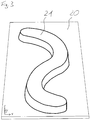
- FIG. 3 A three-dimensional representation of a sheet metal part 20 with bulge 21 produced in this way is shown in the perspective view of FIG Fig. 3 shown.
- the corresponding CAM device (such as the one described in US Pat Fig. 1 shown machine 10 or an external computer) are fed a model.
- This is conventionally derived from a three-dimensional model generated by a computer aided design (CAD) method.
- CAD computer aided design
- it must be determined which tool is to be used for generating the three-dimensional forming.
- this information must be determined manually and, if necessary, fed into a CAM device, which is both time-consuming and labor-intensive.
- the invention is therefore based on the object of specifying a system and a method for the automatic recognition of three-dimensional transformations in a three-dimensional model of a sheet metal part, by means of which an automatic assignment of a tool generating the forming can be determined from a three-dimensional model of the sheet metal part with a forming.
- the first section of section S2 and the second section of section S4 can extend in particular perpendicular to the plane spanned by the first direction X and the second direction Y level. This enables a particularly accurate reproduction of the tool type.
- first cutting section S2 and the second cutting section S4 may extend at respective positions in the first direction X and the second direction Y at which the bulge starts or ends.
- the cut sections S2 and S4 close directly to the bulge, whereby the outline of the bulge is reproduced particularly accurately, which increases the security of the assignment to a corresponding tool type.
- the computer unit is designed to produce a further vertical section, which is different from the said vertical section, and to subject the further vertical cross-sectional contour of the recess resulting from the further vertical section to a Fourier transformation in order to obtain a specific vertical section Fourier coefficients of the further vertical cross-sectional outline to determine.
- This embodiment offers the possibility of obtaining a clear assignment to a tool type through the further vertical cut, if such a clear assignment by the first vertical cut was not possible.
- the Fourier coefficient of the first vertical section may be discarded and only the Fourier coefficient of the further vertical section may be used for the assignment.
- an assignment can be made via two or more vertical sections become.
- the inventive system may further comprise a display unit and the computer unit may be configured to request a manual input of tool data via the display unit if no corresponding tool data is stored in the memory unit for the determined Fourier coefficients. In this way it is possible to complete the assignment table and to integrate new tool types.
- the computer unit can moreover be designed to generate from the data of the three-dimensional model of the sheet metal part a two-dimensional model of the sheet metal part in the plane spanned by the first direction X and the second direction Y and to integrate into the two-dimensional model the determined or input tool data ,
- a data record can be generated which contains in particular all information necessary for use in a CAM device in compressed form. This data can be used by the CAM device directly to control a CAM process for the automated production of a sheet metal part with a corresponding bulge.
- the computer unit is designed to use the determined or input tool data as a text module in the two-dimensional model of the Sheet metal part to integrate.
- This embodiment is particularly suitable for the pictorial reproduction of a model of a piece of sheet metal with bulge, since here the tool type can also be detected directly visually by a user.
- the input unit may be further configured to input tool data for storage in the allocation table of the storage unit. In this way, the assignment table can be supplemented manually or automatically or adapted to new tool types.
- a system for the automatic detection of three-dimensional transformations on in a three-dimensional model of a sheet metal part.
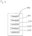
- a system according to a first embodiment of the invention comprises an input unit 100, for example an interface for data transmission or a user interface of mouse and keyboard, for the manual or automatic input of data of a three-dimensional model of a sheet metal part, a computer unit 200, which comprises a processor and is designed to carry out the method steps necessary for recognizing the transformations, a memory unit 300 for storing an allocation table, and optionally a display unit 400, eg a monitor, for communication with a user and an output unit 500 Input unit 100, the memory unit 300, the display unit 400 and the output unit 500 are functionally connected to the computer unit 200.
- an input unit 100 for example an interface for data transmission or a user interface of mouse and keyboard
- a computer unit 200 which comprises a processor and is designed to carry out the method steps necessary for recognizing the transformations
- a memory unit 300 for storing an allocation table
- a display unit 400
- Fig. 5 represents a perspective view of the sheet metal part 20 with the bulge 21 of Fig. 3 as a three-dimensional model, as it is produced for example in the context of a CAD method.
- the sheet metal part 20 of the three-dimensional model extends in a plane defined by a first direction X and a second direction Y, the protrusion 21 being formed in a direction Z, so that the sheet metal part 20 with the protrusion 21 overall forms a three-dimensional unit.
- Fig. 5 are additionally shown two cutting planes, namely a horizontal sectional plane H parallel to the plane spanned by the first and the second direction X, Y and a vertical sectional plane V perpendicular to the plane spanned by the first and the second direction X, Y level.
- first of all a horizontal section along the horizontal sectional plane H and a vertical section along the vertical sectional plane V are executed by the three-dimensional model.
- the layers of the horizontal sectional plane H and the vertical sectional plane V drawn in the figure are given by way of example only. They can also be applied at other locations of the bulge 21, as long as they each intersect the bulge 21.
- the horizontal section and the vertical section a horizontal or a vertical cross-sectional outline of the bulge 21 are generated, which form in the embodiment shown in each case a closed contour.
- the horizontal section preferably runs between a highest point 21a of the bulge 21 in the Z direction and the side of the sheet metal piece 20 which is closest to the highest point 21a in the Z direction.
- the said side of the sheet metal piece 20 is an upper side 20a, which in the context of the invention is defined as being the side on which the convexity of the bulge is formed.
- the "highest point" 21a in the present case as can be seen from the figure, a flat planar area, which forms the upper end of the bulge 21, in other words the top.
- the horizontal cut can be made to be only slightly below the highest point 21a, i. only slightly below the top of the bulge 21 extends.
- lightly in the context of the invention, for example, a distance of a few microns to a few mm to understand.
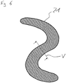
- the vertical section may be set at various positions along the extending direction of the protrusion 21, but it is preferably made perpendicular to the current direction at the interface (the extending direction is in FIG Fig. 6 indicated by arrows).
- Fig. 6 is shown in plan view, the closed horizontal cross-sectional outline, which results from the horizontal section described above. Since the horizontal section in the present case only slightly below the top of the bulge 21, the area corresponds within the cross-sectional contour shown, approximately the area of the top of the bulge 21 as shown in FIG Fig. 5 is shown. Through the line V through the cross-sectional outline of Fig. 6 the vertical section is indicated, which the in Fig. 7 shown view results.
- Fig. 5 Does not have the bulge as in Fig. 5 shown a shape with a route, for example, the in Fig. 5 shown S-shape with two end points, but a closed shape, such as a ring, resulting from the horizontal cut not a closed contour, but two, in this case circular contours, namely the inner circle contour and the outer circle contour of the circular bulge.
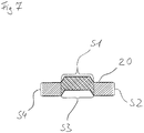
- the vertical section leads perpendicular to the plane spanned by the first direction X and the second direction Y also to a closed cross-sectional outline, which is composed of a series of several sections, namely a convex section S1, a first section of section S2 , a concave section S3 and a second section section S4.
- the convex section S1 extends from the top of the sheet metal piece 20 here obliquely upwards in the Z direction, then passes into a flat part, which here runs parallel to the top of the sheet metal piece 20, and extends laterally obliquely down to in turn to the top of the sheet metal piece 20.
- the adjoining cutting section line S2 extends here in the Z direction vertically downwards from the top of the sheet metal piece 20 to an opposite bottom thereof.
- the concave subsection S3 is here again from an obliquely upwardly extending part, an adjoining approximately parallel to the top of the sheet metal piece 20th and an obliquely downwardly extending portion composed.
- the cross-sectional contour is finally closed by the section section S4, which extends here substantially perpendicularly between the underside of the sheet metal piece 20 and the top thereof.
- two closed cross-sectional contours are obtained by the two sections, which represent a closed polygon.
- a closed polygon can be subjected to a Fourier transformation, by means of which a Fourier coefficient F1, F2 is obtained for each closed polygon.
- the method of Fourier transformation is well known to those skilled in the computer-aided design art, such as Bronstein, Semendjajew, Taschenbuch der Mathematik, and will therefore not be discussed further here.
- a corresponding allocation table which links different Fourier coefficients F1, F2 with corresponding tool data, can be found in the in Fig. 4 be shown stored memory unit 300.
- the tool data can then be output via the output unit 500 of FIG Fig. 4 issued and one example CAM device, as in Fig. 1 shown is supplied.
- the convex part S1 generally represents the part which extends between respective positions in the first direction X and the second direction Y, where the bulge starts and ends, above the top of the sheet piece 20.
- the concave subsection S3 generally represents that subsection which extends between respective positions in the first direction X and the second direction Y, at which the bulge begins or ends, above the underside of the sheet metal piece 20.
- a horizontal section through the bulge of the model is calculated.
- a plane parallel to the direction X and to the direction Y is used to determine their sectional area with the bulge.
- a plane perpendicular to the plane spanned by X direction and Y direction is used to obtain a cross-sectional area of the sheet piece.
- the orientation of the plane is preferably carried out here so that it is perpendicular to the longitudinal course of the bulge.
- the cross-sectional area is limited where it stands out from the sheet metal part. It is there where the bulge deviates for the first time in the direction Z from the base of the sheet metal part, the cross-sectional area perpendicular to the sheet metal of the sheet metal part limited.
- a step St4 the closed cross-sectional contours obtained by the cuts are Fourier-transformed to obtain Fourier coefficients of the cross-sectional contours. For a bulge having a variable extent in the Z direction, it may be necessary to calculate two or more vertical cuts and corresponding coefficients to uniquely determine a tool.
- the Fourier coefficients thus obtained are assigned in a next step St5 tool data of a tool type, for example using a predefined assignment table. For this purpose, coefficients moving in certain tolerance ranges are searched in the table, and tool information stored for corresponding coefficients, for example an identification number of the tool, is read out. If no corresponding tool information is available for the coefficients, the user is requested to enter corresponding information. In this case, the entered information is permanently stored in the allocation table and is also available for later use cases.
- step St6 the output of the tool data of the tool type determined in this way takes place.
- control components of the computer unit may optionally be replaced by the use of a dongle, i. a device that is not replicable and whose presence is required and queried by the in-house control components to be secured against unauthorized entry of data.
- a dongle i. a device that is not replicable and whose presence is required and queried by the in-house control components to be secured against unauthorized entry of data.
- the invention is not limited to determining the coefficients for the association between the bulge to be formed and the tool by Fourier transformation. Although this is advantageous since the center of gravity of the tool can be determined from the hereby determined Fourier coefficients. The latter is helpful for the positioning of the tool to the workpiece.
- other transformations in particular integral transformations, for example the Laplace transform, can be used to determine the coefficients.
- junctors ... "and”, “or” and “either ... or” are used in the meaning that is based on the logical conjunction, the logical adjunct (often “and / or"), or the logical contravalence are.
- system comprises a display unit (400) and the computer unit (200) is adapted to request a manual input of tool data via the display unit (400) if for the determined Fourier coefficients no corresponding tool data in the memory unit (300) are stored.
- the computer unit (300) is designed to integrate the determined or entered tool data as a text module in the two-dimensional model of the sheet metal part (20).
- the input unit (100) is further configured to input tool data for storage in the allocation table of the storage unit (300).
Landscapes
- Engineering & Computer Science (AREA)
- Physics & Mathematics (AREA)
- General Physics & Mathematics (AREA)
- Manufacturing & Machinery (AREA)
- Mathematical Physics (AREA)
- Automation & Control Theory (AREA)
- Human Computer Interaction (AREA)
- Mathematical Analysis (AREA)
- Computational Mathematics (AREA)
- Pure & Applied Mathematics (AREA)
- Data Mining & Analysis (AREA)
- Mathematical Optimization (AREA)
- Theoretical Computer Science (AREA)
- Geometry (AREA)
- General Engineering & Computer Science (AREA)
- Software Systems (AREA)
- Databases & Information Systems (AREA)
- Algebra (AREA)
- Discrete Mathematics (AREA)
- Numerical Control (AREA)
- Punching Or Piercing (AREA)
Description
Die Erfindung betrifft ein System und ein Verfahren zum automatischen Erkennen von dreidimensionalen Umformungen in einem dreidimensionalen Modell eines Blechteils.The invention relates to a system and a method for automatically detecting three-dimensional transformations in a three-dimensional model of a sheet metal part.
Die genannten Umformungen, wie z.B. Näpfe oder Sicken, können in der Praxis beispielsweise durch eine Maschine 10, welche in
In
Eine dreidimensionale Darstellung eines auf diese Weise hergestellten Blechteils 20 mit Ausbuchtung 21 ist in der perspektivischen Ansicht von
Bei der Herstellung solcher Blechteile muss, falls die Herstellung automatisiert mittels eines CAM-Verfahrens erfolgen soll, der entsprechenden CAM-Vorrichtung (wie z.B. der in
Der Erfindung liegt daher die Aufgabe zugrunde, ein System und ein Verfahren zum automatischen Erkennen von dreidimensionalen Umformungen in einem dreidimensionalen Modell eines Blechteils anzugeben, mittels derer sich aus einem dreidimensionalen Modell des Blechteils mit einer Umformung eine automatische Zuordnung eines die Umformung erzeugenden Werkzeugs ermitteln lässt.The invention is therefore based on the object of specifying a system and a method for the automatic recognition of three-dimensional transformations in a three-dimensional model of a sheet metal part, by means of which an automatic assignment of a tool generating the forming can be determined from a three-dimensional model of the sheet metal part with a forming.
Diese Aufgabe wird durch ein System nach Anspruch 1 bzw. ein Verfahren nach Anspruch 10 gelöst. Bevorzugte Ausgestaltungen sind in den Unteransprüchen angegeben.This object is achieved by a system according to
Ein System zum automatischen Erkennen von dreidimensionalen Umformungen in einem dreidimensionalen Modell eines Blechteils gemäß der Erfindung weist Folgendes auf:
- eine Eingabeeinheit zum Eingeben von Daten eines dreidimensionalen Modells eines Blechteils, welches sich in einer durch eine erste Richtung X und eine zweiten Richtung Y aufgespannten Ebene erstreckt, wobei das Blechteil eine Ausbuchtung in eine dritte Richtung Z aufweist, welche zur ersten Richtung X und zur zweiten Richtung Y senkrecht ist;
- eine Rechnereinheit, die dafür ausgelegt ist, einen horizontalen Schnitt mit dem dreidimensionalen Modell durch die Ausbuchtung parallel zu der durch die erste Richtung X und die zweite Richtung Y aufgespannten Ebene zu erzeugen, um einen geschlossenen zweidimensionalen horizontalen Querschnittsumriss der Ausbuchtung zu erhalten; sowie mindestens einen vertikalen Schnitt senkrecht zu der durch die erste Richtung X und die zweite Richtung Y aufgespannte Ebene des Blechteils zu erzeugen, um einen geschlossenen zweidimensionalen vertikalen Querschnittsumriss der Ausbuchtung zu erhalten, der sich zusammensetzt aus einer konvexen Teilstrecke S1, einer ersten Schnittteilstrecke S2, einer konkaven Teilstrecke S3 und einer zweiten Schnittteilstrecke S4, wobei sich die erste Schnittteilstrecke S2 und die zweite Schnittteilstrecke S4 jeweils zwischen einer ersten Seite des Blechs und einer gegenüberliegenden zweiten Seite desselben erstrecken, und
- die Rechnereinheit weiter dafür ausgelegt ist, den horizontalen und den vertikalen Querschnittsumriss einer Fouriertransformation zu unterziehen, um spezifische Fourierkoeffizienten F1, F2 des horizontalen und des vertikalen Querschnittsumrisses zu ermitteln;
- mindestens eine Speichereinheit, auf welcher eine Zuordnungstabelle gespeichert ist, die den Fourierkoeffizienten F1, F2 Werkzeugdaten zuordnet, wobei die Werkzeugdaten einen Werkzeugtyp angeben, und wobei die Rechnereinheit auf die Speichereinheit zugreifen kann, um die Werkzeugdaten durch die ermittelten Fourierkoeffizienten zu ermitteln; und
- mindestens eine Ausgabeeinheit zum Ausgeben der Daten des dreidimensionalen Modells zusammen mit den Werkzeugdaten.
- an input unit for inputting data of a three-dimensional model of a sheet metal part which extends in a plane spanned by a first direction X and a second direction Y, the sheet metal part having a bulge in a third direction Z, which extends to the first direction X and to the second direction Direction Y is vertical;
- a computing unit configured to generate a horizontal cross-section with the three-dimensional model through the protrusion parallel to the plane spanned by the first direction X and the second direction Y to obtain a closed two-dimensional horizontal cross-sectional outline of the protrusion; and to produce at least one vertical section perpendicular to the plane of the sheet-metal part spanned by the first direction X and the second direction Y in order to obtain a closed two-dimensional vertical cross-sectional outline of the bulge consisting of a convex section S1, a first section of section S2, a concave section S3 and a second section section S4, wherein the first section section S2 and the second section section S4 each extend between a first side of the sheet and an opposite second side thereof, and
- the computer unit is further adapted to subject the horizontal and the vertical cross-sectional contour to a Fourier transform to obtain specific ones Determine Fourier coefficients F1, F2 of the horizontal and vertical cross-sectional outlines;
- at least one memory unit on which an allocation table is stored, which assigns the Fourier coefficients F1, F2 tool data, the tool data indicating a tool type, and wherein the computer unit can access the memory unit to determine the tool data by the determined Fourier coefficients; and
- at least one output unit for outputting the data of the three-dimensional model together with the tool data.
Unter Einsatz des erfindungsgemäßen Systems werden somit zwei Schnitte durch das dreidimensionale Modell der Ausbuchtung des Blechstücks erhalten, die eine Information über den Werkzeugtyp erlauben, durch welchen die Ausbuchtung erzeugt werden kann. Die Verknüpfung zwischen der Information über den Werkzeugtyp und der durch die Schnitte erhaltenen Querschnittsumrisse erfolgt über eine Fourier-Transformation der letztgenannten sowie eine Zuordnung der Fourierkoeffizienten, die sich aus der Transformation ergeben, durch eine Zuordnungstabelle. Auf diese Weise kann über die Ausgabeeinheit eine Werkzeuginformation ausgegeben werden, die in einem CAM-Prozess zur Auffindung des entsprechenden Werkzeugtyps verwendet werden kann. Auf diese Weise entfällt die bisher notwendige manuelle Eingabe der Werkzeugdaten in eine CAM-Vorrichtung, welche mit einem hohen Zeit- und Arbeitsaufwand verbunden ist. Durch die Verwendung von Fourierkoeffizienten anstelle der kompletten geometrischen Daten des Werkzeugs in einer Werkzeugdatenbank ist das Suchen und Auffinden entsprechender Werkzeuge mit geringerem technischen Aufwand möglich, da eine Liste der Koeffizienten schneller durchsucht werden kann als eine Vielzahl komplexer Werkzeuggeometriedaten.Using the system according to the invention thus two sections are obtained by the three-dimensional model of the bulge of the sheet metal piece, which allow information about the type of tool through which the bulge can be generated. The link between the information about the tool type and the cross-sectional outlines obtained by the cuts is made by a Fourier transformation of the latter as well as an assignment of the Fourier coefficients resulting from the transformation by an allocation table. In this way, tool information can be output via the output unit, which can be used in a CAM process to find the corresponding tool type. In this way, eliminates the previously necessary manual input of the tool data in a CAM device, which is associated with a lot of time and effort. By using Fourier coefficients instead of the complete geometrical data of the tool in a tool database, it is possible to search for and find corresponding tools with less technical effort since a list of the coefficients can be searched faster than a large number of complex tool geometry data.
Die erste Schnittteilstrecke S2 und die zweite Schnittteilstrecke S4 können sich insbesondere senkrecht zu der durch die erste Richtung X und die zweite Richtung Y aufgespannten Ebene erstrecken. Hierbei wird eine besonders genaue Wiedergabe des Werkzeugtyps ermöglicht.The first section of section S2 and the second section of section S4 can extend in particular perpendicular to the plane spanned by the first direction X and the second direction Y level. This enables a particularly accurate reproduction of the tool type.
Ferner ist es möglich, dass sich die erste Schnittteilstrecke S2 und die zweite Schnittteilstrecke S4 an jeweiligen Positionen in der ersten Richtung X und der zweiten Richtung Y erstreckten, an denen die Ausbuchtung beginnt bzw. endet. Mit anderen Worten schließen sich die Schnittteilstrecken S2 und S4 unmittelbar an die Ausbuchtung an, wodurch der Umriss der Ausbuchtung besonders exakt wiedergegeben wird, was die Sicherheit der Zuordnung zu einem entsprechenden Werkzeugtyp erhöht.Furthermore, it is possible for the first cutting section S2 and the second cutting section S4 to extend at respective positions in the first direction X and the second direction Y at which the bulge starts or ends. In other words, the cut sections S2 and S4 close directly to the bulge, whereby the outline of the bulge is reproduced particularly accurately, which increases the security of the assignment to a corresponding tool type.
Gemäß einer weiteren Ausgestaltung der Erfindung ist die Rechnereinheit dafür ausgelegt, einen weiteren vertikalen Schnitt zu erzeugen, welcher von dem genannten vertikalen Schnitt verschieden ist, und den sich durch den weiteren vertikalen Schnitt ergebenden weiteren vertikalen Querschnittsumriss der Ausbuchtung einer Fouriertransformation zu unterziehen, um einen spezifischen Fourierkoeffizienten des weiteren vertikalen Querschnittsumrisses zu ermitteln. Diese Ausgestaltung bietet die Möglichkeit, durch den weiteren vertikalen Schnitt eine eindeutige Zuordnung zu einem Werkzeugtyp zu erhalten, wenn eine solche eindeutige Zuordnung durch den ersten vertikalen Schnitt nicht möglich war. In diesem Fall kann der Fourierkoeffizient des ersten vertikalen Schnitts verworfen werden und für die Zuordnung lediglich der Fourierkoeffizient des weiteren vertikalen Schnitts verwendet werden. Ferner kann eine Zuordnung über beide oder mehrere vertikale Schnitte getroffen werden. Auf diese Weise kann die Treffsicherheit des Systems in Bezug auf die Werkzeuginformation erhöht werden, oder auch unterschiedliche und variable Profiltiefen behandelt werden. Selbstverständlich können mehrere weitere vertikale Schnitte an verschiedenen Stellen erzeugt werden, bis eine eindeutige Zuordnung des entsprechenden Fourierkoeffizienten zu einem Werkzeugtyp möglich ist.According to a further embodiment of the invention, the computer unit is designed to produce a further vertical section, which is different from the said vertical section, and to subject the further vertical cross-sectional contour of the recess resulting from the further vertical section to a Fourier transformation in order to obtain a specific vertical section Fourier coefficients of the further vertical cross-sectional outline to determine. This embodiment offers the possibility of obtaining a clear assignment to a tool type through the further vertical cut, if such a clear assignment by the first vertical cut was not possible. In this case, the Fourier coefficient of the first vertical section may be discarded and only the Fourier coefficient of the further vertical section may be used for the assignment. Furthermore, an assignment can be made via two or more vertical sections become. In this way, the accuracy of the system with respect to the tool information can be increased, or even different and variable tread depths are treated. Of course, several more vertical sections can be created at different locations until an unambiguous assignment of the corresponding Fourier coefficient to a tool type is possible.
Das erfindungsgemäße System kann ferner eine Anzeigeeinheit aufweisen und die Rechnereinheit kann dafür ausgelegt sein, eine manuelle Eingabe von Werkzeugdaten über die Anzeigeeinheit anzufordern, wenn für die ermittelten Fourierkoeffizienten keine entsprechenden Werkzeugdaten in der Speichereinheit gespeichert sind. Auf diese Weise ist es möglich, die Zuordnungstabelle zu ergänzen und neue Werkzeugtypen zu integrieren.The inventive system may further comprise a display unit and the computer unit may be configured to request a manual input of tool data via the display unit if no corresponding tool data is stored in the memory unit for the determined Fourier coefficients. In this way it is possible to complete the assignment table and to integrate new tool types.
Die Rechnereinheit kann darüber hinaus dafür ausgelegt sein, aus den Daten des dreidimensionalen Modells des Blechteils ein zweidimensionales Modell des Blechteils in der durch die erste Richtung X und die zweite Richtung Y aufgespannten Ebene zu erzeugen und in das zweidimensionale Modell die ermittelten oder eingegebenen Werkzeugdaten zu integrieren. Somit kann ein Datensatz erzeugt werden, der insbesondere alle für den Einsatz in einer CAM-Vorrichtung notwendigen Informationen in komprimierter Form enthält. Diese Daten können von der CAM-Vorrichtung unmittelbar zur Steuerung eines CAM-Verfahrens zur automatisierten Herstellung eines Blechteils mit entsprechender Ausbuchtung eingesetzt werden.The computer unit can moreover be designed to generate from the data of the three-dimensional model of the sheet metal part a two-dimensional model of the sheet metal part in the plane spanned by the first direction X and the second direction Y and to integrate into the two-dimensional model the determined or input tool data , Thus, a data record can be generated which contains in particular all information necessary for use in a CAM device in compressed form. This data can be used by the CAM device directly to control a CAM process for the automated production of a sheet metal part with a corresponding bulge.
Bei einer weiteren Ausgestaltung der Erfindung ist Rechnereinheit dafür ausgelegt, die ermittelten oder eingegebenen Werkzeugdaten als Textbaustein in das zweidimensionale Modell des Blechteils zu integrieren. Diese Ausgestaltung eignet sich insbesondere für die bildliche Wiedergabe eines Modells eines Blechstücks mit Ausbuchtung, da hier der Werkzeugtyp auch unmittelbar optisch durch einen Benutzer erfasst werden kann. Die Eingabeeinheit kann weiter dafür ausgelegt sein, Werkzeugdaten zur Speicherung in der Zuordnungstabelle der Speichereinheit einzugeben. Auf diese Weise kann die Zuordnungstabelle manuell oder automatisch ergänzt bzw. neuen Werkzeugtypen angepasst werden.In a further embodiment of the invention, the computer unit is designed to use the determined or input tool data as a text module in the two-dimensional model of the Sheet metal part to integrate. This embodiment is particularly suitable for the pictorial reproduction of a model of a piece of sheet metal with bulge, since here the tool type can also be detected directly visually by a user. The input unit may be further configured to input tool data for storage in the allocation table of the storage unit. In this way, the assignment table can be supplemented manually or automatically or adapted to new tool types.
Um einen Querschnittsumriss zu erhalten, welcher dem einzusetzenden Werkzeugtyp möglichst exakt entspricht, ist es vorzuziehen, dass der horizontale Schnitt auf einer Höhe in der dritten Richtung Z erfolgt, die zwischen dem höchsten Punkt der Ausbuchtung und derjenigen Seite des Blechstücks liegt, auf welcher die Konvexität der Ausbuchtung ausgebildet ist. Ein erfindungsgemäßes Verfahren zum automatischen Erkennen von dreidimensionalen Umformungen in einem dreidimensionalen Modell eines Blechteils weist die folgenden Schritte auf:
- Erfassen von Daten eines dreidimensionalen Modells eines Blechteils, welches sich in einer durch eine erste Richtung X und eine zweite Richtung Y aufgespannten Ebene erstreckt, wobei das Blechteil eine Ausbuchtung in eine dritte Richtung Z aufweist, welche zu der durch die erste Richtung X und die zweite Richtung Y aufgespannten Ebene senkrecht ist;
- Erzeugen eines horizontalen Schnitts mit dem dreidimensionalen Modell durch die Ausbuchtung parallel zu der durch die erste Richtung X und die zweite Richtung Y aufgespannte Ebene, um einen geschlossenen zweidimensionalen horizontalen Querschnittsumriss der Ausbuchtung zu erhalten; sowie
- Erzeugen mindestens eines vertikalen Schnitts senkrecht zu der durch die erste Richtung X und die zweite Richtung Y aufgespannten Ebene des Blechteils, um einen geschlossenen zweidimensionalen vertikalen Querschnittsumriss der Ausbuchtung zu erhalten, der sich zusammensetzt aus einer konvexen Teilstrecke S1, einer ersten Schnittteilstrecke S2, einer konkaven Teilstrecke S3 und einer zweiten Schnittteilstrecke S4, wobei sich die erste Schnittteilstrecke S2 und die zweite Schnittteilstrecke S4 jeweils zwischen einer ersten Seite des Blechs und einer gegenüberliegenden zweiten Seite desselben erstrecken, Anwenden einer Fourier-Transformation auf den horizontalen Querschnittsumriss und den vertikalen Querschnittsumriss, um spezifische Fourierkoeffizienten F1, F2 des horizontalen und des vertikalen Querschnittsumrisses zu ermitteln;
- Speichern einer Zuordnungstabelle, die den Fourierkoeffizienten F1, F2 Werkzeugdaten zugeordnet, wobei die Werkzeugdaten einen Werkzeugtyp angeben; und
- Ausgeben der Daten des dreidimensionalen Modells zusammen mit den Werkzeugdaten.
- Acquiring data of a three-dimensional model of a sheet metal part which extends in a plane spanned by a first direction X and a second direction Y, the sheet metal part having a bulge in a third direction Z which extends through the first direction X and the second direction Direction Y spanned plane is perpendicular;
- Creating a horizontal cross-section with the three-dimensional model through the protrusion parallel to the plane spanned by the first direction X and the second direction Y to obtain a closed two-dimensional horizontal cross-sectional outline of the protrusion; such as
- Generating at least one vertical section perpendicular to the plane of the sheet metal part spanned by the first direction X and the second direction Y to obtain a closed two-dimensional vertical cross-sectional outline of the bulge composed of a convex section S1, a first section section S2, a concave section Section S3 and a second section section S4, wherein the first section section S2 and the second section section S4 each extend between a first side of the panel and an opposite second side thereof, applying a Fourier transformation to the horizontal cross-sectional outline and the vertical cross-sectional outline to be specific Determine Fourier coefficients F1, F2 of the horizontal and vertical cross-sectional outlines;
- Storing an allocation table associated with the Fourier coefficients F1, F2 tool data, the tool data indicating a tool type; and
- Output the data of the three-dimensional model together with the tool data.
Die durch das erfindungsgemäße Verfahren erzielbaren Vorteile und Effekte sind gleich denjenigen, die vorstehend in Zusammenhang mit dem erfindungsgemäßen System beschrieben wurden.The advantages and effects obtainable by the method according to the invention are similar to those described above in connection with the system according to the invention.
Die Erfindung wird im Folgenden anhand eines Ausführungsbeispiels mit Bezug auf die beigefügten Zeichnungen näher erläutert. In den Zeichnungen zeigen:
- Fig. 1
- eine Maschine zur Herstellung einer Umformung in einem Blechteil;
- Fig. 2
- in der Maschine von
Fig. 1 einsetzbare Umformwerkzeuge; - Fig. 3
- ein Blechstück mit einer dreidimensionalen Umformung, welche durch die Maschine von
Fig. 1 erzeugt werden kann; - Fig. 4
- eine schematische Darstellung eines Systems gemäß einer Ausführungsform der Erfindung;
- Fig. 5
- das Blechstück mit Umformung von
Fig. 5 mit eingezeichneten Schnittebenen für einen horizontalen Schnitt und einen vertikalen Schnitt; - Fig. 6
- eine Ansicht des horizontalen Schnitts durch die Umformung in dem Blechteil von
Fig. 5 ; - Fig. 7
- eine Ansicht des vertikalen Schnitts durch die Umformung im Blechteil von
Fig. 6 ; und - Fig. 8
- ein Flussdiagramm, welches die Schritte eines Verfahrens nach einer Ausführungsform der Erfindung veranschaulicht.
- Fig. 1
- a machine for producing a deformation in a sheet metal part;
- Fig. 2
- in the machine of
Fig. 1 usable forming tools; - Fig. 3
- a sheet metal piece with a three-dimensional forming, which by the machine of
Fig. 1 can be generated; - Fig. 4
- a schematic representation of a system according to an embodiment of the invention;
- Fig. 5
- the sheet metal piece with deformation of
Fig. 5 with drawn cutting planes for a horizontal cut and a vertical cut; - Fig. 6
- a view of the horizontal section through the deformation in the sheet metal part of
Fig. 5 ; - Fig. 7
- a view of the vertical section through the deformation in the sheet metal part of
Fig. 6 ; and - Fig. 8
- a flow chart illustrating the steps of a method according to an embodiment of the invention.
In
Mit nunmehrigem Bezug auf
In
Durch den horizontalen Schnitt und den vertikalen Schnitt werden ein horizontaler bzw. ein vertikaler Querschnittsumriss der Ausbuchtung 21 erzeugt, welche im gezeigten Ausführungsbeispiel jeweils eine geschlossene Kontur bilden. Dabei verläuft der horizontale Schnitt vorzugsweise zwischen einem in Z-Richtung höchstgelegenen Punkt 21a der Ausbuchtung 21 und derjenigen Seite des Blechstücks 20, welche dem höchstgelegenen Punkt 21a in Z-Richtung am nächsten liegt. Bei der genannten Seite des Blechstücks 20 handelt es sich um eine Oberseite 20a, welche im Rahmen der Erfindung so definiert ist, dass sie die Seite ist, auf welcher die Konvexität der Ausbuchtung ausgebildet ist. Der "höchste Punkt" 21a ist im vorliegenden Fall, wie aus der Figur zu entnehmen ist, ein ebener flächiger Bereich, welcher den oberen Abschluss der Ausbuchtung 21, mit anderen Worten deren Oberseite, bildet. Insbesondere kann der horizontale Schnitt so gemacht werden, dass er nur geringfügig unterhalb des höchsten Punktes 21a d.h. nur geringfügig unterhalb der Oberseite der Ausbuchtung 21 verläuft. Unter "geringfügig" ist im Rahmen der Erfindung beispielsweise ein Abstand von wenigen µm bis wenigen mm zu verstehen.By the horizontal section and the vertical section, a horizontal or a vertical cross-sectional outline of the
Demgegenüber kann der vertikale Schnitt an verschiedenen Stellen entlang der Verlaufsrichtung der Ausbuchtung 21 gesetzt werden, wobei er jedoch vorzugsweise senkrecht zur momentanen Verlaufsrichtung an der Schnittstelle gemacht wird (die Verlaufsrichtung ist in
In
Hat die Ausbuchtung nicht wie in
Wie in
Somit werden durch die beiden Schnitte zwei geschlossene Querschnittsumrisse erhalten, die einen geschlossenen Polygonzug darstellen. Ein solcher geschlossener Polygonzug kann, wie dies bekannt ist, einer Fourier-Transformation unterzogen werden, durch die für jeden geschlossenen Polygonzug ein Fourierkoeffizient F1, F2 erhalten wird. Das Verfahren der Fourier-Transformation ist dem Fachmann auf dem Gebiet der computerunterstützten Konstruktion wohlbekannt, beispielsweise aus Bronstein, Semendjajew, Taschenbuch der Mathematik, und soll deshalb an dieser Stelle nicht näher erläutert werden.Thus, two closed cross-sectional contours are obtained by the two sections, which represent a closed polygon. As is known, such a closed polygon can be subjected to a Fourier transformation, by means of which a Fourier coefficient F1, F2 is obtained for each closed polygon. The method of Fourier transformation is well known to those skilled in the computer-aided design art, such as Bronstein, Semendjajew, Taschenbuch der Mathematik, and will therefore not be discussed further here.
Mittels dieser Fourierkoeffizienten F1, F2 lässt sich eine Zuordnung der Geometrie der Ausbuchtung 21 zu einem Werkzeug treffen, mittels dessen eine Ausbuchtung 21 mit dieser Geometrie erzeugt werden kann.By means of these Fourier coefficients F1, F2, an assignment of the geometry of the
Sind weitere Querschnittsumrisse vorhanden, beispielsweise im Falle einer ringförmigen Ausbuchtung zwei horizontale Querschnittsumrisse, kann eine Zuordnung durch die Bildung entsprechender weiterer Fourierkoeffizienten gebildet werden.If further cross-sectional contours are present, for example two horizontal cross-sectional contours in the case of an annular bulge, an association can be formed by the formation of corresponding further Fourier coefficients.
Eine entsprechende Zuordnungstabelle, welche verschiedene Fourierkoeffizienten F1, F2 mit entsprechenden Werkzeugdaten verknüpft, kann in der in
Es ist anzumerken, dass die konvexe Teilstrecke S1 allgemein diejenige Teilstrecke darstellt, welche sich zwischen jeweiligen Positionen in der ersten Richtung X und der zweiten Richtung Y, an denen die Ausbuchtung beginnt bzw. endet, oberhalb der Oberseite des Blechstücks 20 erstreckt. Auf ähnliche Weise stellt die konkave Teilstrecke S3 allgemein diejenige Teilstrecke dar, welche sich zwischen jeweiligen Positionen in der ersten Richtung X und der zweiten Richtung Y, an denen die Ausbuchtung beginnt bzw. endet, oberhalb der Unterseite des Blechstücks 20 erstreckt.It is to be noted that the convex part S1 generally represents the part which extends between respective positions in the first direction X and the second direction Y, where the bulge starts and ends, above the top of the
Dies hat auch zum Ergebnis, dass sich für unterschiedliche Umformhöhen unterschiedliche Querschnittsumrisse durch den vertikalen Schnitt ergeben. Dies schlägt sich wiederum in unterschiedlichen Fourierkoeffizienten für den Querschnittsumriss nieder. Aufgrund der noch vorhandenen Ähnlichkeiten der Fourierkoeffizienten kann auf ein dafür verwendbares Werkzeug geschlossen werden, und es können zusätzlich dafür benötigte Bearbeitungsparameter wie beispielsweise die Eindringtiefe ermittelt werden.This also has the result that, for different forming heights, different cross-sectional outlines result from the vertical cut. This in turn is reflected in different Fourier coefficients for the cross-sectional outline. Due to the similarities of the Fourier coefficients that are still present, it is possible to deduce a tool that can be used for this purpose, and additional machining parameters, such as, for example, the penetration depth, can additionally be determined for this purpose.
Der Ablauf eines erfindungsgemäßen Verfahrens lässt sich dem schematischen Flussdiagramm von
Demzufolge werden in einem ersten Schritt St1 Daten einer dreidimensionalen Abbildung (= 3D-Abbildung) eines Blechteils mit einer dreidimensionalen Umformung erfasst. Dies erfolgt beispielsweise durch Erstellen eines dreidimensionalen Modell durch einen Benutzer auf dem System oder durch Übermitteln eines solchen Modells an das erfindungsgemäße System.As a result, in a first step St1, data of a three-dimensional image (= 3D image) of a sheet metal part with a three-dimensional transformation is detected. This is done, for example, by creating a three-dimensional model by a user on the system or by communicating such a model to the system of the invention.
Anschließend wird in einem Schritt St2 ein horizontaler Schnitt durch die Ausbuchtung des Modells berechnet. Hierzu wird eine Ebene parallel zur Richtung X und zur Richtung Y eingesetzt, um deren Schnittfläche mit der Ausbuchtung zu ermitteln.Subsequently, in a step St2, a horizontal section through the bulge of the model is calculated. For this purpose, a plane parallel to the direction X and to the direction Y is used to determine their sectional area with the bulge.
In einem Schritt St3 werden ein oder mehrere vertikale Schnitte durch die Ausbuchtung (dreidimensionale Umformung) des Modells ausgeführt. Hierbei wird eine Ebene senkrecht zu der durch Richtung X und Richtung Y aufgespannten Ebene verwendet, um eine Querschnittsfläche des Blechstücks zu erhalten. Die Ausrichtung der Ebene erfolgt hier vorzugsweise so, dass sie senkrecht zum Längsverlauf der Ausbuchtung verläuft. Um einen geschlossenen Querschnittsumriss der Ausbuchtung zu erhalten, wird die Querschnittsfläche dort, wo sie sich von dem Blechteil abhebt, begrenzt. Es wird dafür dort, wo die Ausbuchtung erstmalig in Richtung Z von der Grundfläche des Blechteils abweicht, die Querschnittsfläche senkrecht zum Blech des Blechteils begrenzt.In a step St3, one or more vertical sections are performed by the bulge (three-dimensional transformation) of the model. Here, a plane perpendicular to the plane spanned by X direction and Y direction is used to obtain a cross-sectional area of the sheet piece. The orientation of the plane is preferably carried out here so that it is perpendicular to the longitudinal course of the bulge. In order to obtain a closed cross-sectional contour of the bulge, the cross-sectional area is limited where it stands out from the sheet metal part. It is there where the bulge deviates for the first time in the direction Z from the base of the sheet metal part, the cross-sectional area perpendicular to the sheet metal of the sheet metal part limited.
Danach werden in einem Schritt St4 die durch die Schnitte erhaltenen geschlossenen Querschnittsumrisse einer Fourier-Transformation unterzogen, um Fourierkoeffizienten der Querschnittsumrisse zu erhalten. Für eine Ausbuchtung mit in ihrem Verlauf variabler Ausdehnung in Richtung Z kann es erforderlich sein, zwei oder mehrere vertikale Schnitte und entsprechende Koeffizienten zu berechnen, um ein Werkzeug eindeutig zu bestimmen.Thereafter, in a step St4, the closed cross-sectional contours obtained by the cuts are Fourier-transformed to obtain Fourier coefficients of the cross-sectional contours. For a bulge having a variable extent in the Z direction, it may be necessary to calculate two or more vertical cuts and corresponding coefficients to uniquely determine a tool.
Den so erhaltenen Fourierkoeffizienten werden in einem nächsten Schritt St5 Werkzeugdaten eines Werkzeugtyps zugeordnet, beispielsweise mit Hilfe einer vordefinierten Zuordnungstabelle. Hierfür wird in der Tabelle nach sich in bestimmten Toleranzbereichen bewegenden Koeffizienten gesucht, und zu entsprechenden Koeffizienten gespeicherte Werkzeuginformation, beispielsweise eine Identifikationsnummer des Werkzeugs, ausgelesen. Sollte zu den Koeffizienten keine entsprechende Werkzeuginformation vorhanden sein, wird der Benutzer aufgefordert, entsprechende Information einzugeben. In diesem Fall wird die eingegebene Information dauerhaft in der Zuordnungstabelle gespeichert und steht auch für spätere Anwendungsfälle zur Verfügung.The Fourier coefficients thus obtained are assigned in a next step St5 tool data of a tool type, for example using a predefined assignment table. For this purpose, coefficients moving in certain tolerance ranges are searched in the table, and tool information stored for corresponding coefficients, for example an identification number of the tool, is read out. If no corresponding tool information is available for the coefficients, the user is requested to enter corresponding information. In this case, the entered information is permanently stored in the allocation table and is also available for later use cases.
Schließlich erfolgt in einem Schritt St6 die Ausgabe der Werkzeugdaten des so ermittelten Werkzeugtyps.Finally, in a step St6, the output of the tool data of the tool type determined in this way takes place.
Einzelne Komponenten des Systems, beispielsweise Steuerkomponenten der Rechnereinheit können gegebenenfalls durch Einsatz eines Dongles, d.h. einer Vorrichtung, die nicht replizierbar ist und deren Präsenz von den Steuerkomponenten für den eigenen Betrieb erforderlich ist und abgefragt wird, gegen unautorisiertes Einspeisen von Daten gesichert werden.Individual components of the system, for example control components of the computer unit, may optionally be replaced by the use of a dongle, i. a device that is not replicable and whose presence is required and queried by the in-house control components to be secured against unauthorized entry of data.
Dem Fachmann ist offensichtlich, dass innerhalb des Umfangs der Ansprüche Abwandlungen der oben ohnehin nur beispielhaft beschriebenen Ausführungsform möglich sind. So ist die Erfindung nicht auf das beschriebene abgeflachte Profil der Ausbuchtung beschränkt, sondern auf jedes Profil anwendbar. Ferner ist es nicht nur auf laufende Umformungswerkzeuge beschränkt, sondern auch auf Stanz- oder Stempelwerkzeuge oder andere anwendbar.It will be apparent to those skilled in the art that within the scope of the claims, variations of the embodiment already described above by way of example only are possible. Thus, the invention is not limited to the described flattened profile of the bulge, but applicable to each profile. Further, it is not limited only to current forming tools, but also applicable to punching or stamping tools or others.
Insbesondere ist die Erfindung nicht darauf beschränkt, die Koeffizienten für die Zuordnung zwischen der zu formenden Ausbuchtung und dem Werkzeug mittels Fourier-Transformation zu bestimmen. Diese ist zwar vorteilhaft, da aus den hiermit ermittelten Fourierkoeffizienten der Schwerpunkt des Werkzeugs bestimmt werden kann. Letzteres ist hilfreich für die Positionierung des Werkzeugs zum Werkstück. Alternativ können andere Transformationen, insbesondere Integraltransformationen, beispielsweise die Laplace-Transformation zur Bestimmung der Koeffizienten verwendet werden.In particular, the invention is not limited to determining the coefficients for the association between the bulge to be formed and the tool by Fourier transformation. Although this is advantageous since the center of gravity of the tool can be determined from the hereby determined Fourier coefficients. The latter is helpful for the positioning of the tool to the workpiece. Alternatively, other transformations, in particular integral transformations, for example the Laplace transform, can be used to determine the coefficients.
Die Junktoren ... "und", "oder" und "entweder ... oder" werden in der Bedeutung verwendet, die an die logische Konjunktion, die logische Adjunktion (oft "und/oder"), bzw. die logische Contravalenz angelehnt sind.The junctors ... "and", "or" and "either ... or" are used in the meaning that is based on the logical conjunction, the logical adjunct (often "and / or"), or the logical contravalence are.
Offenbart ist ein System gemäß der Erfindung, wobei das System eine Anzeigeeinheit (400) aufweist und die Rechnereinheit (200) dafür ausgelegt ist, eine manuelle Eingabe von Werkzeugdaten über die Anzeigeeinheit (400) anzufordern wenn für die ermittelten Fourierkoeffizienten keine entsprechenden Werkzeugdaten in der Speichereinheit (300) gespeichert sind.Disclosed is a system according to the invention, wherein the system comprises a display unit (400) and the computer unit (200) is adapted to request a manual input of tool data via the display unit (400) if for the determined Fourier coefficients no corresponding tool data in the memory unit (300) are stored.
Bei diesem System ist die Rechnereinheit (300) dafür ausgelegt, die ermittelten oder eingegebenen Werkzeugdaten als Textbaustein in das zweidimensionale Modell des Blechteils (20) zu integrieren.In this system, the computer unit (300) is designed to integrate the determined or entered tool data as a text module in the two-dimensional model of the sheet metal part (20).
Bei diesem System ist die Eingabeeinheit (100) weiter dafür ausgelegt, Werkzeugdaten zur Speicherung in der Zuordnungstabelle der Speichereinheit (300) einzugeben.In this system, the input unit (100) is further configured to input tool data for storage in the allocation table of the storage unit (300).
Offenbart ist ferner ein erfindungsgemäßes Verfahren, das ferner den Schritt aufweist:
- Anfordern einer manuellen Eingabe von Werkzeugdaten über eine Anzeigeeinheit (400), wenn für die ermittelten Fourierkoeffizienten keine entsprechenden Werkzeugdaten (300) gespeichert sind.
- Request manual entry of tool data via a display unit (400) when no corresponding tool data (300) is stored for the determined Fourier coefficients.
Das Verfahren kann ferner den Schritt aufweisen:
- Integrieren der ermittelten oder eingegebenen Werkzeugdaten als Textbaustein in das zweidimensionale Modell des Blechteils (20).
- Integrating the determined or input tool data as a text module in the two-dimensional model of the sheet metal part (20).
Das Verfahren kann ferner den Schritt aufweisen:
- Eingeben von Werkzeugdaten zur Speicherung in der Zuordnungstabelle.
- Entering tool data for storage in the allocation table.
Claims (16)
- A system for automatically detecting three-dimensional shaping in a three-dimensional model of a sheet-metal part (20), comprising:an input unit (100) for inputting data of a three-dimensional model of a sheet-metal part (20) which extends in a plane spanned by a first direction X and a second direction Y, wherein the sheet-metal part (20) comprises a bulge (21) in a third direction Z which is perpendicular to a plane spanned by the first direction X and the second direction Y;a computing unit (200) adaptedto generate a horizontal cut with the three-dimensional model through the bulge (21) parallel to the plane spanned by the first direction X and the second direction Y, to obtain at least one closed two-dimensional horizontal cross-sectional contour of the bulge (21); as well asto generate at least one vertical cut perpendicular to the plane spanned by the first direction X and the second direction Y of the sheet-metal part (20), to obtain a respective closed two-dimensional vertical cross-sectional contour of the bulge (21) for each vertical cut, which is composed ofa convex partial segment (S1),a first partial cut segment (S2),a concave partial segment (S3), anda second partial cut segment (S4),wherein the first partial cut segment (S2) and the second partial cut segment (S4) each extend between a first side of the sheet-metal (20) and an opposing second side thereof, andwherein the computing unit (200) is further adapted to subject the at least one horizontal and the vertical cross-sectional contour to a transformation so as to determine specific transformation coefficients (F1, F2) of the at least one horizontal and the vertical cross-sectional contour;at least one storage unit (300) in which an allocation table is stored, which allocates tool data to the transformation coefficients (F1, F2), wherein the tool data indicates a type of tool, and wherein the computing unit (200) can access to the storage unit to determine the tool data by the determined transformation coefficients; andat least one output unit for outputting the data of the three-dimensional model together with tool data.
- The system according to claim 1, wherein the transformation is a Fourier transformation, in particular a discrete Fourier transformation, and the transformation coefficients are Fourier coefficients.
- The system according to claim 1 or 2, wherein
the computing unit (200) is adapted to obtain by the horizontal cut two closed two-dimensional horizontal cross-sectional contours of the bulge (21), and
the computing unit (200) is adapted to subject the first as well as the second vertical cross-sectional contour to a transformation to obtain specific transformation coefficients. - The system according to one of claims 1 to 3, wherein the first partial cut segment (S2) and the second partial cut segment (S4) extend perpendicular to the plane spanned by the first direction X and the second direction Y.
- The system according to one of claims 1 to 4, wherein the first partial cut segment (S2) and the second partial cut segment (S4) extend at respective positions in the first direction X and the second direction Y, at which the bulge begins or ends, respectively.
- The system according to one of claims 1 to 5, wherein the computing unit (200) is adapted to produce a further vertical cut, which is different from the mentioned vertical cut, and to subject the further vertical cross-sectional contour of the bulge (21), which results from the further vertical cut, to a Fourier transformation so as to determine specific Fourier coefficients (F3) of the further vertical cross-sectional contour.
- The system according to one of claims 1 to 6, wherein the computing unit (300) is adapted to produce a two-dimensional model of the sheet-metal part (20) in the plane spanned by the first direction X and the second direction Y from the data of the three-dimensional model of the sheet-metal part (20) and to integrate the determined or input tool data into the two-dimensional model.
- The system according to one of the preceding claims, wherein the horizontal cut is formed at a height in the third direction Z which is located between the highest point of the bulge (21) and that side of the sheet-metal part (20), on which the convexity of the bulge is formed.
- A method for automatically detecting three-dimensional shaping in a three-dimensional model of a sheet-metal part (20), which comprises the following steps:acquiring data of a three-dimensional model of a sheet-metal part (200) which extends in a plane spanned by a first direction X and a second direction Y, wherein the sheet-metal part (20) comprises a bulge (21) in a third direction Z which is perpendicular to the plane spanned by the first direction X and the second direction Y;generating a horizontal cut with the three-dimensional model through the bulge (21) parallel to the plane spanned by the first direction X and the second direction Y, to obtain at least one closed two-dimensional horizontal cross-sectional contour of the bulge (21); as well asgenerating at least one vertical cut perpendicular to the plane spanned by the first direction X and the second direction Y of the sheet-metal part (20), to obtain a respective closed two-dimensional vertical cross-sectional contour of the bulge (21) for each vertical cut, which is composed ofa convex partial segment (S1),a first partial cut segment (S2),a concave partial segment (S3), anda second partial cut segment (S4),wherein the first partial cut segment (S2) and the second partial cut segment (S4) each extend between a first side of the sheet-metal (20) and an opposing second side thereof,applying a transformation to the at least one horizontal cross-sectional contour and the vertical cross-sectional contour, to determine specific Fourier coefficients (F1, F2) of the at least one horizontal and the vertical cross-sectional contours;storing an allocation table which allocates tool data to the Fourier coefficients (F1, F2), wherein the tool data indicate a type of tool; andoutputting the data of the three-dimensional model together with the tool data.
- The method according to claim 9, wherein the transformation is a Fourier transformation, in particular a discrete Fourier transformation, and the transformation coefficients are Fourier coefficients.
- The method according to one of claims 9 or 10, wherein
two closed two-dimensional horizontal cross-sectional contours of the bulge (21) are obtained during generation of the horizontal cuts, and
upon application of the transformation, the transformation is applied to the first as well as to the second vertical cross-sectional contour to obtain specific transformation coefficients for the first as well as the second horizontal cross-sectional contour. - The method according to one of claims 9 to 11, wherein during the generation of the vertical cut the first partial cut segment (S2) and the second partial cut segment (S4) extend perpendicular to the plane spanned by the first direction X and the second direction Y.
- The method according to one of claims 9 to 12, wherein during generation of the vertical cut the first partial cut segment (S2) and the second partial cut segment (S4) extend at respective positions in the first direction X and the second direction Y, at which the bulge begins or ends, respectively.
- The method according to one of claims 9 to 13, further comprising the steps:generating a further vertical cut, which differs from the mentioned vertical cut, andapplying a Fourier transformation to the further vertical cross-sectional contour of the bulge (21) generated by the further vertical step, to determine a specific Fourier coefficient (F3) of the further vertical cross-sectional contour.
- The method according to one of claims 9 to 14, further comprising the step:generating from the data of the three-dimensional model of the sheet-metal part (200) a two-dimensional model of the sheet-metal part (20) in the plane spanned by the first direction X and the second direction Y andintegrating the determined or input tool data into the two-dimensional model.
- The method according to one of claims 9 to 14, wherein during generation of the horizontal cut this step is performed at a height in the third direction Z, which is located between the highest point of the bulge (21) and that side of the sheet-metal part (20), on which the convexity of the bulge is formed.
Applications Claiming Priority (2)
| Application Number | Priority Date | Filing Date | Title |
|---|---|---|---|
| DE102013211960.7A DE102013211960A1 (en) | 2013-06-24 | 2013-06-24 | System and method for detecting deformations |
| PCT/EP2014/001597 WO2014206532A1 (en) | 2013-06-24 | 2014-06-12 | System and method for detecting shaping |
Publications (2)
| Publication Number | Publication Date |
|---|---|
| EP3000000A1 EP3000000A1 (en) | 2016-03-30 |
| EP3000000B1 true EP3000000B1 (en) | 2017-05-17 |
Family
ID=51063390
Family Applications (1)
| Application Number | Title | Priority Date | Filing Date |
|---|---|---|---|
| EP14735465.8A Active EP3000000B1 (en) | 2013-06-24 | 2014-06-12 | System and method for detecting shaping |
Country Status (5)
| Country | Link |
|---|---|
| US (1) | US10133259B2 (en) |
| EP (1) | EP3000000B1 (en) |
| JP (1) | JP6316415B2 (en) |
| DE (1) | DE102013211960A1 (en) |
| WO (1) | WO2014206532A1 (en) |
Families Citing this family (2)
| Publication number | Priority date | Publication date | Assignee | Title |
|---|---|---|---|---|
| DE4119562A1 (en) | 1991-06-13 | 1992-12-17 | Wacker Chemie Gmbh | METHOD FOR WATER REPELLENT IMPREGNATION OF MASONRY |
| AT519761B1 (en) * | 2017-03-17 | 2018-10-15 | Trumpf Maschinen Austria Gmbh & Co Kg | Bending step selection process carried out on a control system of a bending machine |
Family Cites Families (7)
| Publication number | Priority date | Publication date | Assignee | Title |
|---|---|---|---|---|
| JP2636666B2 (en) * | 1993-03-29 | 1997-07-30 | 村田機械株式会社 | Tool assignment method to sheet metal processing figure |
| JP3223478B2 (en) * | 1993-06-23 | 2001-10-29 | 株式会社日立製作所 | NC code automatic programming method and apparatus for turret punch press with numerical control |
| US7110848B2 (en) * | 2002-06-24 | 2006-09-19 | Ryozo Shibano | Computer program product |
| US7885722B2 (en) * | 2006-03-23 | 2011-02-08 | Autoform Engineering Gmbh | Method planning for manufacturing sheet-metal forming parts |
| DE102009021136A1 (en) * | 2009-05-13 | 2010-12-16 | Fraunhofer-Gesellschaft zur Förderung der angewandten Forschung e.V. | control device |
| JP5610800B2 (en) * | 2010-03-16 | 2014-10-22 | キヤノン株式会社 | Optical element manufacturing method |
| DE102011013044A1 (en) * | 2011-03-08 | 2012-09-13 | GM Global Technology Operations LLC (n. d. Gesetzen des Staates Delaware) | Method for quantitative evaluation of surface defects of vehicle components, involves determining edge of defect area by comparing large deformation with predetermined threshold value |
-
2013
- 2013-06-24 DE DE102013211960.7A patent/DE102013211960A1/en not_active Ceased
-
2014
- 2014-06-12 JP JP2016522305A patent/JP6316415B2/en active Active
- 2014-06-12 EP EP14735465.8A patent/EP3000000B1/en active Active
- 2014-06-12 WO PCT/EP2014/001597 patent/WO2014206532A1/en not_active Ceased
-
2015
- 2015-12-24 US US14/998,327 patent/US10133259B2/en active Active
Also Published As
| Publication number | Publication date |
|---|---|
| US10133259B2 (en) | 2018-11-20 |
| US20160124426A1 (en) | 2016-05-05 |
| WO2014206532A1 (en) | 2014-12-31 |
| DE102013211960A1 (en) | 2014-12-24 |
| JP6316415B2 (en) | 2018-04-25 |
| EP3000000A1 (en) | 2016-03-30 |
| JP2016523418A (en) | 2016-08-08 |
Similar Documents
| Publication | Publication Date | Title |
|---|---|---|
| DE60132706T2 (en) | METHOD AND DEVICE FOR GENERATING NUMERICAL CONTROL DATA | |
| DE112016005969B4 (en) | tool path correction device and tool path correction method | |
| DE2142178A1 (en) | Method and arrangement for manufacturing a tool | |
| DE112017006552T5 (en) | MACHINING PROCESS GENERATING DEVICE, MACHINING PROCESS GENERATING METHOD AND PROGRAM | |
| DE102019107363B4 (en) | Method and system for determining a property of a machine, in particular a machine tool, without measuring the property and method for determining an expected quality condition of a component manufactured with a machine | |
| DE112019007232B4 (en) | STATE ESTIMATION DEVICE AND STATE ESTIMATION METHOD | |
| DE112006003623T5 (en) | Method for transforming G code into a Step NC part program | |
| DE102023107884A1 (en) | Tool identification method, tool identification device, setting and/or measuring device and computer-implemented method | |
| DE112008002298T5 (en) | Device, method and program for generating a tool reference plane | |
| DE69910207T2 (en) | AUTOMATIC PROGRAMMING DEVICE AND STORAGE MEDIA FOR STORING THE GRAPHIC DATA GENERATING PROGRAM | |
| EP3000000B1 (en) | System and method for detecting shaping | |
| DE102018127821A1 (en) | Method for calculating optimized machine-readable cutting curves for a laser cutting device | |
| DE10129676A1 (en) | Method for determining the effects of design decisions | |
| EP3329332B1 (en) | Method for determining supporting points of a test plan | |
| WO2022152457A1 (en) | Method for producing a device for moving a workpiece from a first tool into a second tool, electronic computing unit, computer program product and computer-readable medium | |
| EP2118618B1 (en) | Method for determining measuring points | |
| EP1297458B1 (en) | Method for automatically preparing a working plan | |
| EP4492286A1 (en) | Process for planning tool paths and cam system for tool machining | |
| DE102020126993A1 (en) | ADAPTIVE RAIL GENERATION FOR PROCESSING WITH CNC CONTROL | |
| EP4130656A1 (en) | Preparation of the evaluation of samples of measured values from a measurement of a plurality of workpieces by one or more coordinate measuring devices | |
| EP4125013A1 (en) | Production of a work plan for a component | |
| WO2017041986A1 (en) | Method and device for generating a sectional view of a body of a vehicle | |
| DE102019131456A1 (en) | Method for determining a property of a machine, in particular a machine tool, without measuring the property | |
| EP4538813A1 (en) | Method for providing a work plan for producing a component, computer program and data carrier | |
| DE102024122111A1 (en) | Design system for generating a virtual target geometry of a component, method for generating a virtual target geometry of a component, and method for manufacturing a component. |
Legal Events
| Date | Code | Title | Description |
|---|---|---|---|
| PUAI | Public reference made under article 153(3) epc to a published international application that has entered the european phase |
Free format text: ORIGINAL CODE: 0009012 |
|
| 17P | Request for examination filed |
Effective date: 20151222 |
|
| AK | Designated contracting states |
Kind code of ref document: A1 Designated state(s): AL AT BE BG CH CY CZ DE DK EE ES FI FR GB GR HR HU IE IS IT LI LT LU LV MC MK MT NL NO PL PT RO RS SE SI SK SM TR |
|
| AX | Request for extension of the european patent |
Extension state: BA ME |
|
| DAX | Request for extension of the european patent (deleted) | ||
| GRAP | Despatch of communication of intention to grant a patent |
Free format text: ORIGINAL CODE: EPIDOSNIGR1 |
|
| INTG | Intention to grant announced |
Effective date: 20161209 |
|
| GRAS | Grant fee paid |
Free format text: ORIGINAL CODE: EPIDOSNIGR3 |
|
| GRAA | (expected) grant |
Free format text: ORIGINAL CODE: 0009210 |
|
| AK | Designated contracting states |
Kind code of ref document: B1 Designated state(s): AL AT BE BG CH CY CZ DE DK EE ES FI FR GB GR HR HU IE IS IT LI LT LU LV MC MK MT NL NO PL PT RO RS SE SI SK SM TR |
|
| REG | Reference to a national code |
Ref country code: GB Ref legal event code: FG4D Free format text: NOT ENGLISH |
|
| REG | Reference to a national code |
Ref country code: CH Ref legal event code: EP |
|
| REG | Reference to a national code |
Ref country code: IE Ref legal event code: FG4D Free format text: LANGUAGE OF EP DOCUMENT: GERMAN |
|
| REG | Reference to a national code |
Ref country code: AT Ref legal event code: REF Ref document number: 895013 Country of ref document: AT Kind code of ref document: T Effective date: 20170615 |
|
| REG | Reference to a national code |
Ref country code: DE Ref legal event code: R096 Ref document number: 502014003887 Country of ref document: DE |
|
| REG | Reference to a national code |
Ref country code: CH Ref legal event code: NV Representative=s name: R. A. EGLI AND CO. PATENTANWAELTE, CH |
|
| REG | Reference to a national code |
Ref country code: SE Ref legal event code: TRGR |
|
| REG | Reference to a national code |
Ref country code: NL Ref legal event code: FP |
|
| REG | Reference to a national code |
Ref country code: LT Ref legal event code: MG4D |
|
| PG25 | Lapsed in a contracting state [announced via postgrant information from national office to epo] |
Ref country code: LT Free format text: LAPSE BECAUSE OF FAILURE TO SUBMIT A TRANSLATION OF THE DESCRIPTION OR TO PAY THE FEE WITHIN THE PRESCRIBED TIME-LIMIT Effective date: 20170517 Ref country code: FI Free format text: LAPSE BECAUSE OF FAILURE TO SUBMIT A TRANSLATION OF THE DESCRIPTION OR TO PAY THE FEE WITHIN THE PRESCRIBED TIME-LIMIT Effective date: 20170517 Ref country code: NO Free format text: LAPSE BECAUSE OF FAILURE TO SUBMIT A TRANSLATION OF THE DESCRIPTION OR TO PAY THE FEE WITHIN THE PRESCRIBED TIME-LIMIT Effective date: 20170817 Ref country code: ES Free format text: LAPSE BECAUSE OF FAILURE TO SUBMIT A TRANSLATION OF THE DESCRIPTION OR TO PAY THE FEE WITHIN THE PRESCRIBED TIME-LIMIT Effective date: 20170517 Ref country code: GR Free format text: LAPSE BECAUSE OF FAILURE TO SUBMIT A TRANSLATION OF THE DESCRIPTION OR TO PAY THE FEE WITHIN THE PRESCRIBED TIME-LIMIT Effective date: 20170818 Ref country code: HR Free format text: LAPSE BECAUSE OF FAILURE TO SUBMIT A TRANSLATION OF THE DESCRIPTION OR TO PAY THE FEE WITHIN THE PRESCRIBED TIME-LIMIT Effective date: 20170517 |
|
| PG25 | Lapsed in a contracting state [announced via postgrant information from national office to epo] |
Ref country code: RS Free format text: LAPSE BECAUSE OF FAILURE TO SUBMIT A TRANSLATION OF THE DESCRIPTION OR TO PAY THE FEE WITHIN THE PRESCRIBED TIME-LIMIT Effective date: 20170517 Ref country code: IS Free format text: LAPSE BECAUSE OF FAILURE TO SUBMIT A TRANSLATION OF THE DESCRIPTION OR TO PAY THE FEE WITHIN THE PRESCRIBED TIME-LIMIT Effective date: 20170917 Ref country code: LV Free format text: LAPSE BECAUSE OF FAILURE TO SUBMIT A TRANSLATION OF THE DESCRIPTION OR TO PAY THE FEE WITHIN THE PRESCRIBED TIME-LIMIT Effective date: 20170517 Ref country code: BG Free format text: LAPSE BECAUSE OF FAILURE TO SUBMIT A TRANSLATION OF THE DESCRIPTION OR TO PAY THE FEE WITHIN THE PRESCRIBED TIME-LIMIT Effective date: 20170817 Ref country code: PL Free format text: LAPSE BECAUSE OF FAILURE TO SUBMIT A TRANSLATION OF THE DESCRIPTION OR TO PAY THE FEE WITHIN THE PRESCRIBED TIME-LIMIT Effective date: 20170517 |
|
| PG25 | Lapsed in a contracting state [announced via postgrant information from national office to epo] |
Ref country code: CZ Free format text: LAPSE BECAUSE OF FAILURE TO SUBMIT A TRANSLATION OF THE DESCRIPTION OR TO PAY THE FEE WITHIN THE PRESCRIBED TIME-LIMIT Effective date: 20170517 Ref country code: EE Free format text: LAPSE BECAUSE OF FAILURE TO SUBMIT A TRANSLATION OF THE DESCRIPTION OR TO PAY THE FEE WITHIN THE PRESCRIBED TIME-LIMIT Effective date: 20170517 Ref country code: DK Free format text: LAPSE BECAUSE OF FAILURE TO SUBMIT A TRANSLATION OF THE DESCRIPTION OR TO PAY THE FEE WITHIN THE PRESCRIBED TIME-LIMIT Effective date: 20170517 Ref country code: SK Free format text: LAPSE BECAUSE OF FAILURE TO SUBMIT A TRANSLATION OF THE DESCRIPTION OR TO PAY THE FEE WITHIN THE PRESCRIBED TIME-LIMIT Effective date: 20170517 Ref country code: RO Free format text: LAPSE BECAUSE OF FAILURE TO SUBMIT A TRANSLATION OF THE DESCRIPTION OR TO PAY THE FEE WITHIN THE PRESCRIBED TIME-LIMIT Effective date: 20170517 |
|
| REG | Reference to a national code |
Ref country code: DE Ref legal event code: R097 Ref document number: 502014003887 Country of ref document: DE |
|
| PG25 | Lapsed in a contracting state [announced via postgrant information from national office to epo] |
Ref country code: SM Free format text: LAPSE BECAUSE OF FAILURE TO SUBMIT A TRANSLATION OF THE DESCRIPTION OR TO PAY THE FEE WITHIN THE PRESCRIBED TIME-LIMIT Effective date: 20170517 Ref country code: IT Free format text: LAPSE BECAUSE OF FAILURE TO SUBMIT A TRANSLATION OF THE DESCRIPTION OR TO PAY THE FEE WITHIN THE PRESCRIBED TIME-LIMIT Effective date: 20170517 |
|
| REG | Reference to a national code |
Ref country code: IE Ref legal event code: MM4A |
|
| PLBE | No opposition filed within time limit |
Free format text: ORIGINAL CODE: 0009261 |
|
| STAA | Information on the status of an ep patent application or granted ep patent |
Free format text: STATUS: NO OPPOSITION FILED WITHIN TIME LIMIT |
|
| REG | Reference to a national code |
Ref country code: FR Ref legal event code: ST Effective date: 20180228 |
|
| 26N | No opposition filed |
Effective date: 20180220 |
|
| PG25 | Lapsed in a contracting state [announced via postgrant information from national office to epo] |
Ref country code: LU Free format text: LAPSE BECAUSE OF NON-PAYMENT OF DUE FEES Effective date: 20170612 Ref country code: IE Free format text: LAPSE BECAUSE OF NON-PAYMENT OF DUE FEES Effective date: 20170612 |
|
| REG | Reference to a national code |
Ref country code: BE Ref legal event code: MM Effective date: 20170630 |
|
| PG25 | Lapsed in a contracting state [announced via postgrant information from national office to epo] |
Ref country code: FR Free format text: LAPSE BECAUSE OF NON-PAYMENT OF DUE FEES Effective date: 20170717 Ref country code: SI Free format text: LAPSE BECAUSE OF FAILURE TO SUBMIT A TRANSLATION OF THE DESCRIPTION OR TO PAY THE FEE WITHIN THE PRESCRIBED TIME-LIMIT Effective date: 20170517 |
|
| PG25 | Lapsed in a contracting state [announced via postgrant information from national office to epo] |
Ref country code: BE Free format text: LAPSE BECAUSE OF NON-PAYMENT OF DUE FEES Effective date: 20170630 |
|
| PG25 | Lapsed in a contracting state [announced via postgrant information from national office to epo] |
Ref country code: MT Free format text: LAPSE BECAUSE OF FAILURE TO SUBMIT A TRANSLATION OF THE DESCRIPTION OR TO PAY THE FEE WITHIN THE PRESCRIBED TIME-LIMIT Effective date: 20170517 |
|
| GBPC | Gb: european patent ceased through non-payment of renewal fee |
Effective date: 20180612 |
|
| PG25 | Lapsed in a contracting state [announced via postgrant information from national office to epo] |
Ref country code: GB Free format text: LAPSE BECAUSE OF NON-PAYMENT OF DUE FEES Effective date: 20180612 |
|
| PG25 | Lapsed in a contracting state [announced via postgrant information from national office to epo] |
Ref country code: HU Free format text: LAPSE BECAUSE OF FAILURE TO SUBMIT A TRANSLATION OF THE DESCRIPTION OR TO PAY THE FEE WITHIN THE PRESCRIBED TIME-LIMIT; INVALID AB INITIO Effective date: 20140612 Ref country code: MC Free format text: LAPSE BECAUSE OF FAILURE TO SUBMIT A TRANSLATION OF THE DESCRIPTION OR TO PAY THE FEE WITHIN THE PRESCRIBED TIME-LIMIT Effective date: 20170517 |
|
| PG25 | Lapsed in a contracting state [announced via postgrant information from national office to epo] |
Ref country code: CY Free format text: LAPSE BECAUSE OF FAILURE TO SUBMIT A TRANSLATION OF THE DESCRIPTION OR TO PAY THE FEE WITHIN THE PRESCRIBED TIME-LIMIT Effective date: 20170517 |
|
| PG25 | Lapsed in a contracting state [announced via postgrant information from national office to epo] |
Ref country code: MK Free format text: LAPSE BECAUSE OF FAILURE TO SUBMIT A TRANSLATION OF THE DESCRIPTION OR TO PAY THE FEE WITHIN THE PRESCRIBED TIME-LIMIT Effective date: 20170517 |
|
| PG25 | Lapsed in a contracting state [announced via postgrant information from national office to epo] |
Ref country code: PT Free format text: LAPSE BECAUSE OF FAILURE TO SUBMIT A TRANSLATION OF THE DESCRIPTION OR TO PAY THE FEE WITHIN THE PRESCRIBED TIME-LIMIT Effective date: 20170517 |
|
| PG25 | Lapsed in a contracting state [announced via postgrant information from national office to epo] |
Ref country code: AL Free format text: LAPSE BECAUSE OF FAILURE TO SUBMIT A TRANSLATION OF THE DESCRIPTION OR TO PAY THE FEE WITHIN THE PRESCRIBED TIME-LIMIT Effective date: 20170517 |
|
| REG | Reference to a national code |
Ref country code: AT Ref legal event code: MM01 Ref document number: 895013 Country of ref document: AT Kind code of ref document: T Effective date: 20190612 |
|
| PG25 | Lapsed in a contracting state [announced via postgrant information from national office to epo] |
Ref country code: AT Free format text: LAPSE BECAUSE OF NON-PAYMENT OF DUE FEES Effective date: 20190612 |
|
| PGFP | Annual fee paid to national office [announced via postgrant information from national office to epo] |
Ref country code: NL Payment date: 20210618 Year of fee payment: 8 |
|
| PGFP | Annual fee paid to national office [announced via postgrant information from national office to epo] |
Ref country code: CH Payment date: 20210618 Year of fee payment: 8 Ref country code: TR Payment date: 20210609 Year of fee payment: 8 Ref country code: SE Payment date: 20210618 Year of fee payment: 8 |
|
| REG | Reference to a national code |
Ref country code: CH Ref legal event code: PL Ref country code: SE Ref legal event code: EUG |
|
| REG | Reference to a national code |
Ref country code: NL Ref legal event code: MM Effective date: 20220701 |
|
| PG25 | Lapsed in a contracting state [announced via postgrant information from national office to epo] |
Ref country code: NL Free format text: LAPSE BECAUSE OF NON-PAYMENT OF DUE FEES Effective date: 20220701 |
|
| PG25 | Lapsed in a contracting state [announced via postgrant information from national office to epo] |
Ref country code: SE Free format text: LAPSE BECAUSE OF NON-PAYMENT OF DUE FEES Effective date: 20220613 Ref country code: LI Free format text: LAPSE BECAUSE OF NON-PAYMENT OF DUE FEES Effective date: 20220630 Ref country code: CH Free format text: LAPSE BECAUSE OF NON-PAYMENT OF DUE FEES Effective date: 20220630 |
|
| PGFP | Annual fee paid to national office [announced via postgrant information from national office to epo] |
Ref country code: DE Payment date: 20250618 Year of fee payment: 12 |