EP2999768B1 - Verfahren und vorrichtung zur löschung von koks - Google Patents
Verfahren und vorrichtung zur löschung von koks Download PDFInfo
- Publication number
- EP2999768B1 EP2999768B1 EP14733328.0A EP14733328A EP2999768B1 EP 2999768 B1 EP2999768 B1 EP 2999768B1 EP 14733328 A EP14733328 A EP 14733328A EP 2999768 B1 EP2999768 B1 EP 2999768B1
- Authority
- EP
- European Patent Office
- Prior art keywords
- coke
- water
- temperature
- process according
- baffles
- Prior art date
- Legal status (The legal status is an assumption and is not a legal conclusion. Google has not performed a legal analysis and makes no representation as to the accuracy of the status listed.)
- Not-in-force
Links
Images


Classifications
-
- C—CHEMISTRY; METALLURGY
- C10—PETROLEUM, GAS OR COKE INDUSTRIES; TECHNICAL GASES CONTAINING CARBON MONOXIDE; FUELS; LUBRICANTS; PEAT
- C10B—DESTRUCTIVE DISTILLATION OF CARBONACEOUS MATERIALS FOR PRODUCTION OF GAS, COKE, TAR, OR SIMILAR MATERIALS
- C10B39/00—Cooling or quenching coke
- C10B39/02—Dry cooling outside the oven
-
- C—CHEMISTRY; METALLURGY
- C10—PETROLEUM, GAS OR COKE INDUSTRIES; TECHNICAL GASES CONTAINING CARBON MONOXIDE; FUELS; LUBRICANTS; PEAT
- C10B—DESTRUCTIVE DISTILLATION OF CARBONACEOUS MATERIALS FOR PRODUCTION OF GAS, COKE, TAR, OR SIMILAR MATERIALS
- C10B39/00—Cooling or quenching coke
- C10B39/04—Wet quenching
- C10B39/08—Coke-quenching towers
-
- C—CHEMISTRY; METALLURGY
- C10—PETROLEUM, GAS OR COKE INDUSTRIES; TECHNICAL GASES CONTAINING CARBON MONOXIDE; FUELS; LUBRICANTS; PEAT
- C10B—DESTRUCTIVE DISTILLATION OF CARBONACEOUS MATERIALS FOR PRODUCTION OF GAS, COKE, TAR, OR SIMILAR MATERIALS
- C10B39/00—Cooling or quenching coke
- C10B39/04—Wet quenching
-
- C—CHEMISTRY; METALLURGY
- C10—PETROLEUM, GAS OR COKE INDUSTRIES; TECHNICAL GASES CONTAINING CARBON MONOXIDE; FUELS; LUBRICANTS; PEAT
- C10B—DESTRUCTIVE DISTILLATION OF CARBONACEOUS MATERIALS FOR PRODUCTION OF GAS, COKE, TAR, OR SIMILAR MATERIALS
- C10B39/00—Cooling or quenching coke
- C10B39/10—Cooling or quenching coke combined with agitating means, e.g. rotating tables or drums
-
- C—CHEMISTRY; METALLURGY
- C10—PETROLEUM, GAS OR COKE INDUSTRIES; TECHNICAL GASES CONTAINING CARBON MONOXIDE; FUELS; LUBRICANTS; PEAT
- C10B—DESTRUCTIVE DISTILLATION OF CARBONACEOUS MATERIALS FOR PRODUCTION OF GAS, COKE, TAR, OR SIMILAR MATERIALS
- C10B39/00—Cooling or quenching coke
- C10B39/12—Cooling or quenching coke combined with conveying means
-
- C—CHEMISTRY; METALLURGY
- C10—PETROLEUM, GAS OR COKE INDUSTRIES; TECHNICAL GASES CONTAINING CARBON MONOXIDE; FUELS; LUBRICANTS; PEAT
- C10L—FUELS NOT OTHERWISE PROVIDED FOR; NATURAL GAS; SYNTHETIC NATURAL GAS OBTAINED BY PROCESSES NOT COVERED BY SUBCLASSES C10G OR C10K; LIQUIFIED PETROLEUM GAS; USE OF ADDITIVES TO FUELS OR FIRES; FIRE-LIGHTERS
- C10L9/00—Treating solid fuels to improve their combustion
- C10L9/08—Treating solid fuels to improve their combustion by heat treatments, e.g. calcining
-
- F—MECHANICAL ENGINEERING; LIGHTING; HEATING; WEAPONS; BLASTING
- F27—FURNACES; KILNS; OVENS; RETORTS
- F27D—DETAILS OR ACCESSORIES OF FURNACES, KILNS, OVENS OR RETORTS, IN SO FAR AS THEY ARE OF KINDS OCCURRING IN MORE THAN ONE KIND OF FURNACE
- F27D15/00—Handling or treating discharged material; Supports or receiving chambers therefor
- F27D15/02—Cooling
-
- F—MECHANICAL ENGINEERING; LIGHTING; HEATING; WEAPONS; BLASTING
- F27—FURNACES; KILNS; OVENS; RETORTS
- F27D—DETAILS OR ACCESSORIES OF FURNACES, KILNS, OVENS OR RETORTS, IN SO FAR AS THEY ARE OF KINDS OCCURRING IN MORE THAN ONE KIND OF FURNACE
- F27D15/00—Handling or treating discharged material; Supports or receiving chambers therefor
- F27D15/02—Cooling
- F27D15/0286—Cooling in a vertical, e.g. annular, shaft
-
- F—MECHANICAL ENGINEERING; LIGHTING; HEATING; WEAPONS; BLASTING
- F28—HEAT EXCHANGE IN GENERAL
- F28C—HEAT-EXCHANGE APPARATUS, NOT PROVIDED FOR IN ANOTHER SUBCLASS, IN WHICH THE HEAT-EXCHANGE MEDIA COME INTO DIRECT CONTACT WITHOUT CHEMICAL INTERACTION
- F28C3/00—Other direct-contact heat-exchange apparatus
- F28C3/10—Other direct-contact heat-exchange apparatus one heat-exchange medium at least being a fluent solid, e.g. a particulate material
- F28C3/12—Other direct-contact heat-exchange apparatus one heat-exchange medium at least being a fluent solid, e.g. a particulate material the heat-exchange medium being a particulate material and a gas, vapour, or liquid
-
- F—MECHANICAL ENGINEERING; LIGHTING; HEATING; WEAPONS; BLASTING
- F28—HEAT EXCHANGE IN GENERAL
- F28D—HEAT-EXCHANGE APPARATUS, NOT PROVIDED FOR IN ANOTHER SUBCLASS, IN WHICH THE HEAT-EXCHANGE MEDIA DO NOT COME INTO DIRECT CONTACT
- F28D21/00—Heat-exchange apparatus not covered by any of the groups F28D1/00 - F28D20/00
- F28D21/0001—Recuperative heat exchangers
-
- F—MECHANICAL ENGINEERING; LIGHTING; HEATING; WEAPONS; BLASTING
- F28—HEAT EXCHANGE IN GENERAL
- F28D—HEAT-EXCHANGE APPARATUS, NOT PROVIDED FOR IN ANOTHER SUBCLASS, IN WHICH THE HEAT-EXCHANGE MEDIA DO NOT COME INTO DIRECT CONTACT
- F28D7/00—Heat-exchange apparatus having stationary tubular conduit assemblies for both heat-exchange media, the media being in contact with different sides of a conduit wall
- F28D7/0041—Heat-exchange apparatus having stationary tubular conduit assemblies for both heat-exchange media, the media being in contact with different sides of a conduit wall the conduits for only one medium being tubes having parts touching each other or tubes assembled in panel form
-
- F—MECHANICAL ENGINEERING; LIGHTING; HEATING; WEAPONS; BLASTING
- F28—HEAT EXCHANGE IN GENERAL
- F28D—HEAT-EXCHANGE APPARATUS, NOT PROVIDED FOR IN ANOTHER SUBCLASS, IN WHICH THE HEAT-EXCHANGE MEDIA DO NOT COME INTO DIRECT CONTACT
- F28D7/00—Heat-exchange apparatus having stationary tubular conduit assemblies for both heat-exchange media, the media being in contact with different sides of a conduit wall
- F28D7/10—Heat-exchange apparatus having stationary tubular conduit assemblies for both heat-exchange media, the media being in contact with different sides of a conduit wall the conduits being arranged one within the other, e.g. concentrically
- F28D7/106—Heat-exchange apparatus having stationary tubular conduit assemblies for both heat-exchange media, the media being in contact with different sides of a conduit wall the conduits being arranged one within the other, e.g. concentrically consisting of two coaxial conduits or modules of two coaxial conduits
-
- C—CHEMISTRY; METALLURGY
- C10—PETROLEUM, GAS OR COKE INDUSTRIES; TECHNICAL GASES CONTAINING CARBON MONOXIDE; FUELS; LUBRICANTS; PEAT
- C10L—FUELS NOT OTHERWISE PROVIDED FOR; NATURAL GAS; SYNTHETIC NATURAL GAS OBTAINED BY PROCESSES NOT COVERED BY SUBCLASSES C10G OR C10K; LIQUIFIED PETROLEUM GAS; USE OF ADDITIVES TO FUELS OR FIRES; FIRE-LIGHTERS
- C10L2290/00—Fuel preparation or upgrading, processes or apparatus therefore, comprising specific process steps or apparatus units
- C10L2290/06—Heat exchange, direct or indirect
-
- F—MECHANICAL ENGINEERING; LIGHTING; HEATING; WEAPONS; BLASTING
- F28—HEAT EXCHANGE IN GENERAL
- F28D—HEAT-EXCHANGE APPARATUS, NOT PROVIDED FOR IN ANOTHER SUBCLASS, IN WHICH THE HEAT-EXCHANGE MEDIA DO NOT COME INTO DIRECT CONTACT
- F28D21/00—Heat-exchange apparatus not covered by any of the groups F28D1/00 - F28D20/00
- F28D2021/0019—Other heat exchangers for particular applications; Heat exchange systems not otherwise provided for
- F28D2021/0045—Other heat exchangers for particular applications; Heat exchange systems not otherwise provided for for granular materials
-
- Y—GENERAL TAGGING OF NEW TECHNOLOGICAL DEVELOPMENTS; GENERAL TAGGING OF CROSS-SECTIONAL TECHNOLOGIES SPANNING OVER SEVERAL SECTIONS OF THE IPC; TECHNICAL SUBJECTS COVERED BY FORMER USPC CROSS-REFERENCE ART COLLECTIONS [XRACs] AND DIGESTS
- Y02—TECHNOLOGIES OR APPLICATIONS FOR MITIGATION OR ADAPTATION AGAINST CLIMATE CHANGE
- Y02P—CLIMATE CHANGE MITIGATION TECHNOLOGIES IN THE PRODUCTION OR PROCESSING OF GOODS
- Y02P20/00—Technologies relating to chemical industry
- Y02P20/10—Process efficiency
- Y02P20/129—Energy recovery, e.g. by cogeneration, H2recovery or pressure recovery turbines
Definitions
- the present invention refers to the technical field of the metallurgical industry.
- the invention refers to a process for quenching coke produced by distillation of coal (coking) and to a plant for carrying out such process.
- Coke is used as a fuel and as a reducing agent in melting furnaces for ores i.e. in blast furnaces; coke is obtained by refining processes of coal so-called coking plants, which usually are a part of the complex of a steel plant.
- the coking plant comprises furnaces made of a series of cells internally coated with silica or silico-aluminous refractory bricks, placed next to one another in a battery.
- Coal is hermetically closed in cells, which are heated from outside by the flames of a gas burning in the cavity between one cell and the other. Coal remains in the cells at a temperature of about 1200-1300°C for a time of 14/24 hours, during which a good portion of sulfur and volatile matter is released and acquires the characteristics of porosity and mechanical resistance needed for its use in the blast furnace.
- coke acts as a fuel and leads to the temperature necessary for the different chemical reactions to occur, thus producing the reduction of iron ores, and scarries out the carburation of iron.
- coke the temperature of which is of about 1200-1300°C is withdrawn from the furnace by means of a suitable drawing machine.
- the first one involves the transfer of the coke withdrawn from a furnace onto a quenching car for feeding it to a quenching tower.
- the quenching towers are generally equipped with suitable baffles for retaining the particulate entrained by the flow of water vapor that is generated.
- the major drawback lies in the significant amounts of condensed polycyclic hydrocarbons which are emitted together with the steam exiting from the quenching towers.
- the treatment with water of coke the temperature of which is of about 1200-1300°C, in fact gives rise to a sort of steam distillation, in which the water vapor released from the quenching towers entrains also various organic substances, among which the aromatic polycyclic hydrocarbons (IPA), as for example anthracene, acenaphtene, benzopyrene, benzofluorantene, phenanthrene and chrysene, which are well known for their high toxicity and carcinogenity.
- IPA aromatic polycyclic hydrocarbons
- the baffles retaining the particulate provided in the quenching towers are not able to block the totality of emissions of the above mentioned toxic and carcinogenic organic substances into the environment.
- a further drawback is due to the dispersion of a huge quantity of thermal energy occurring when coke is quenched through a simple pouring of water onto it, without any recovery of such thermal energy.
- CDQ Coke Dry Quenching
- Coke is transferred to a suitable hopper, in which a flow of inert gas (for example nitrogen) is the heat exchange means.
- a flow of inert gas for example nitrogen
- the gas passing through the coke gets overheated while the coke cools down.
- CDQ plants are very complex and of great size and for such reasons they are generally built where there is no water available in the liquid state.
- WO-A-88/03549 discloses a method and apparatus for cooling and quenching coke, wherein in a first stage, the coke is cooled by indirect cooling to a temperature of the between 200 and 800°C, preferably between 400 and 650°C, followed by passage through a water bath, which is continuously fed with cold water.
- CN-A-103 087 734 discloses a second stage coke cooler comprising a tubular body closed at the opposite ends by end plates, at least one inlet opening for coke, four (at least one) inlet openings for water, at least one discharge opening and screw.
- the problem underlying the present invention was therefore to provide for a process for quenching coke produced by coking, so as to guarantee a strict control of the emissions not only of particulates but also and especially of organic volatile substances in a steam flow and in particular of polycyclic aromatic hydrocarbons, and also to permit a substantial recovery of thermal energy developed during the quenching phase.
- the aforesaid fluid for lowering the temperature of coke in step a) is water and in such case in step a) steam at high temperature is generated.
- the aforesaid fluid for lowering the temperature of coke in step a) is diathermic oil and in such case the diathermic oil brought to high temperature through heat exchange with the coke is used as a vector and as a heat source in a circuitry for energy recovery.
- the aforesaid continuous flow of water is fed into the turbo-cooler through manifolds arranged longitudinally and externally to said cylindrical tubular body and said at least one inlet opening for the water comprises at least one opening located at one end of said manifolds and a plurality of nozzles branching off from said manifolds and leading to the inner wall of the cylindrical tubular body along its entire length.
- said at least one inlet opening for water also includes a plurality of nozzles for introducing water, formed on said shaft of the rotor.
- the method according to the invention comprises a step of feeding said high-temperature steam generated in step a) to an energy generator for energy recovery.
- the method according to the invention comprise a step of feeding said diathermic oil, brought to a high temperature as a result of heat exchange with the coke, to a generator for energy recovery.
- the method according to the present invention comprises a step of recovering the heat of water vapor discharged from the turbo-cooler in step d), which has a temperature of 600-200°C, for a heat exchange with water having a temperature below 70°C, preferably of 10-50°C, and consequently producing hot water (temperature less than 100°C) for various usages and for waste-to-energy use, and steam at a temperature higher than 100°C, generally of 400-120°C.
- the steam exiting from this heat exchange step is subjected to washing steps, for example using a scrubber, and condensation steps, thus obtaining water which can be fed again to the quenching process, and sludge, which can be dried and pelletized.
- Such sludge having substantially the same chemical composition of the coke, can be sent to a recovery cycle.
- step a) of lowering the temperature of said coke to 700-300°C is preferably carried out by the steps of
- water is fed through the inlet of said serpentine and steam at high temperature (about 350-450°C) is discharged through the outlet of said serpentine.
- the fluid introduced into the serpentine through said inlet is a diathermic oil, which is discharged through the aforesaid outlet at a temperature lower than 300°C, preferably between 200 and 280°C.
- the present invention also concerns a plant for carrying out the aforesaid process, according to any one of claims 14-16.
- the present invention so relates to a hybrid technology, which can be defined “dry” in the first step and “wet” in the second one.
- the process according to the present invention comprises feeding coke coming from the coking step and having a temperature higher than or equal to 900°C into a conduction boiler C, in which a portion of the heat of coke is transferred to water circulating in such boiler for producing steam at a high temperature of about 300-500°C, which is fed to a turbine generator GT for energy recovery.
- a boiler C of this type has the shape of a truncated pyramid with a substantially rectangular base with walls 1 made of metal material and refractory mortars, at the inside of which ducts 2 of metal material are applied with a circular section, said ducts extending vertically with respect to the base.
- each wall 1 The ducts 2 of each wall 1 are in fluid communication with each other and connected to form a sort of serpentine provided with inlet 5 for water and outlet 6 for steam.
- baffles 3 Inside the walls 1 of the boiler C there are arranged a plurality of baffles 3 of metal material, extending vertically with respect to the base of the boiler. Ducts 2 of metal material with circular section and extending perpendicularly with respect to the base are applied onto said baffles. Also the ducts of each baffle 3 are in fluid communication with each other and connected to form a sort of serpentine provided with inlet 5 for water and outlet 6 for steam.
- a drawer 4 is disposed, serving to progressively discharge coke exiting from the boiler C.
- Coke coming from the coking phase and having a temperature higher than or equal to 900°C is then fed into the boiler C by means of a conveyor, for example a chain or belt conveyor, from which coke is discharged onto a distributor 7 placed at the top of the conduction boiler C.
- the distributor 7 assures an uniform feeding of coke in the various compartments of the boiler defined by the baffles 3 and the walls 1.
- a hopper 8 collects the hot coke at the inlet of the boiler.
- the hopper 8 is made of a metal material internally coated with refractory mortars.
- the coke fed to the upper portion of the boiler gradually gives part of its thermal energy to the water circulating in the serpentines formed by the ducts 2 applied to the walls 1 and the baffles 3 and is gradually lowered within the boiler due to the coke removal from the bottom of the boiler, once it has reached a temperature of 700-300°C, by means of the drawer 4.
- a diathermic oil can be used, which also enters the serpentine of the boiler C through the manifold 5 and, after having been branched to the vertical ducts 2, exits from the boiler through the manifold 6, at a temperature lower than 300°C, preferably between 200 and 280°C.
- inert gas generally nitrogen or carbon dioxide
- the feeding of the flow of inert gas can be continuous or just for determined time intervals.
- Coke discharged through the drawer 4 is fed to a turbo-cooler T.
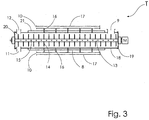
- the turbo-cooler T shown in figure 3 comprises a cylindrical tubular body 18, closed at opposite ends by respective end plates 19, 20, provided with a cooling jacket 21 for the inner wall thereof, intended for being run by a cooling fluid, generally constituted by water, an inlet opening 9 for coke, an inlet opening 10 for water from a set of manifolds 17 provided with nozzles 16, a discharge opening 11 for the cooled coke, a discharge opening 12 for steam and a rotor, rotatably supported in the cylindrical body and comprising a shaft 13 provided with radially projecting elements 14 , which are, for example, rod-, paddle- or plough-shaped and adapted to facilitate the advancement of coke and its mixing with water.
- a plurality of nozzle-shaped openings 15 is present in the shaft 13, for admitting water into the cylindrical tubular body 18.
- Coke is then fed into the turbo-cooler T through the inlet opening 9 placed near the bottom 19 whereas water intended for cooling the coke is fed through the inlet opening 10 of the manifolds 17 to the nozzles 16 located on the cylindrical body of the turbo-cooler and through the other inlet openings consisting of the nozzles 15 on the shaft 13 of the rotor.
- Result is that it is possible to obtain a lowering of the temperature of coke from 700-300°C to 200-100°C with a continuous process and with a residence time of coke inside the turbo-cooler not longer than 30 minutes.
- the steam which is generated inside the turbo-cooler following the heat exchange between coke and water and which has a temperature of about 600-200°C is discharged through the discharge opening 12 and transferred to the heat exchanger S, schematically shown in figure 1 .
- a heat exchange is carried out with water entering at a temperature lower than or equal to 50°C, typically 15-30°C, for bringing it to a temperature of about 70-100°C, so as it can be used with waste-to-energy techniques.
- Coke deriving from a coking phase and having a temperature of about 1100°C was discharged from the top into the conduction boiler C, with a mass flow-rate of 1000 kg/h, and placed into contact with the ducts 2 applied onto the walls 1 and the baffles 3 and fed with diathermic oil at about 230°C with a flow-rate of 2800 kg/h. Coke was periodically removed from the bottom of the boiler C by means of the drawer 4, after an average residence time inside the boiler of 150 minutes.
- the diathermic oil was brought to a temperature of about 300°C, always with a flow-rate of 2800 kg/h, and was transferred to a generator for energy recovery.
- Coke exiting from the boiler having a temperature of about 400°C, was continuously fed with a flow-rate of about 1000 kg/h, to the inside of a turbo-cooler T as described before, through the inlet opening 9.
- a flow-rate of about 1000 kg/h was continuously fed with a flow-rate of about 1000 kg/h, to the inside of a turbo-cooler T as described before, through the inlet opening 9.
- water was introduced into the turbo-cooler T at a temperature of about 60°C with a total flow-rate of 150 kg/h.
- the shaft 13 of the paddled rotor was rotated at a speed of 5 rpm and after an average residence time of 15 minutes coke was continuously discharged from the discharge opening 11 at a temperature of about 100°C, whereas a continuous flow of water wapor was discharged from the opening 12, at a temperature of about 400°C.
- Coke exiting from the turbo-cooler was transferred to the subsequent working steps of the iron and steel industry, in particular to the agglomeration step.
Landscapes
- Engineering & Computer Science (AREA)
- Chemical & Material Sciences (AREA)
- Mechanical Engineering (AREA)
- General Engineering & Computer Science (AREA)
- Oil, Petroleum & Natural Gas (AREA)
- Organic Chemistry (AREA)
- Materials Engineering (AREA)
- Thermal Sciences (AREA)
- Physics & Mathematics (AREA)
- Combustion & Propulsion (AREA)
- Production Of Liquid Hydrocarbon Mixture For Refining Petroleum (AREA)
- Coke Industry (AREA)
- Heat-Exchange Devices With Radiators And Conduit Assemblies (AREA)
- Yarns And Mechanical Finishing Of Yarns Or Ropes (AREA)
- Organic Low-Molecular-Weight Compounds And Preparation Thereof (AREA)
Claims (16)
- Verfahren zum Abschrecken von Koks, der aus der Destillation von Kohle stammt und eine Temperatur von mehr als oder gleich 900°C aufweist, umfassend die folgenden Schritte:a) Absenken der Temperatur des Kokses auf 700 bis 300°C durch Wärmeaustausch mit einem Fluid durch Wände aus einem wärmeleitfähigen Material, das zwischen dem Koks und dem Fluid angeordnet ist,b) Zuführen eines kontinuierlichen Stroms von Koks bei 700 bis 300°C in einen Turbo-Kühler (T), der einen zylindrischen rohrförmigen Körper (18) aufweist, der an gegenüberliegenden Enden jeweils durch Endplatten (19, 20) verschlossen ist, welcher mit einem optionalen Kühlmantel (21) für dessen Innenwand (19, 20), mindestens einer Einlassöffnung (9) für den Koks, mindestens einer Einlassöffnung (10, 15, 16) für Wasser, mindestens einer Austrittsöffnung (11, 12) und einem im zylindrischen Rohrkörper (5) drehbar gelagerten Rotor mit einer Welle (13), die radial von der Welle vorstehenden Elementen (14) umfasst, versehen ist, und der für die Handhabung und den Vorschub des Kokses ausgebildet ist;c) Zuführen eines kontinuierlichen Wasserstroms bei einer Temperatur von weniger als oder gleich 100°C in den Turbo-Kühler (T) durch die mindestens eine Einlassöffnung (10, 15, 16) und Unterwerfen des Koks- und Wasserstroms der Wirkung des Rotors, der den Koks zu der mindestens einen Austrittsöffnung (11) hin vorantreibt;d) kontinuierliches Entnehmen eines Koksstroms bei einer Temperatur von weniger als oder gleich 200°C und eines Wasserdampfstroms aus der mindestens einen Austrittsöffnung (11, 12).
- Verfahren nach Anspruch 1, wobei das für den Wärmeaustausch mit dem Koks in Schritt a) verwendete Fluid diathermisches Öl ist.
- Verfahren nach Anspruch 1, dadurch gekennzeichnet, dass das für den Wärmeaustausch mit dem Koks in Schritt a) verwendete Fluid Wasser ist, das infolge des Wärmeaustausches bei hoher Temperatur in Dampf umgewandelt wird.
- Verfahren nach einem der Ansprüche 1 bis 3, wobei der kontinuierliche Wasserstrom in den Turbo-Kühler (T) durch in Längsrichtung und außerhalb des zylindrischen rohrförmigen Körpers (18) angeordnete Kollektoren (17) eingespeist wird und die Einlassöffnung für das Wasser mindestens eine Öffnung (10) umfasst, die an einem Ende der Kollektoren (17) angeordnet ist und eine Vielzahl von Düsen (16) aufweist, die von den Kollektoren (17) entlang ihrer gesamten Länge abzweigen und zur Innenwand des zylindrischen Rohrkörpers führen (18).
- Verfahren nach einem der Ansprüche 1 bis 4, wobei die mindestens eine Einlassöffnung für Wasser auch eine Mehrzahl von Düsen (15) zum Einführen von Wasser umfasst, die auf der Welle (13) des Rotors ausgebildet sind.
- Verfahren nach Anspruch 3, umfassend einen Schritt des Zuführens des in Schritt a) erzeugten Hochtemperaturdampfes zu einem Generator zur Energierückgewinnung (GT).
- Verfahren nach Anspruch 2, umfassend einen Schritt des Zuführens des diathermischen Öls, das durch Wärmeaustausch mit dem Koks auf eine hohe Temperatur gebracht wird, zu einem Generator (GT) zur Energierückgewinnung.
- Verfahren nach einem der Ansprüche 1 bis 7, umfassend einen Schritt des Durchführens eines Wärmeaustausches zwischen dem aus dem Turbo-Kühler (T) in Schritt d) ausgetragenen Wasserdampf, der eine Temperatur von 600-200°C aufweist und Wasser mit einer Temperatur unter 70°C, vorzugsweise etwa 10-50°C, wobei heißes Wasser von weniger als 100°C für die Verwendung bei der Umwandlung von Abfall zu Energie und Dampf mit einer Temperatur von mehr als 100°C, im Allgemeinen 450-120°C, erhalten werden.
- Verfahren nach Anspruch 8, wobei der Dampf mit einer Temperatur von mehr als 100°C, der durch den Wärmeaustausch mit Wasser erhalten wird, Wasch- und Kondensationsschritten unterworfen wird, wodurch Wasser erhalten wird, das dem Turbokühler (T) in Schritt c) wieder zugeführt werden kann, und Schlamm, der getrocknet wird, erhalten werden.
- Verfahren nach Anspruch 9, wobei der getrocknete Schlamm, der im Wesentlichen die gleiche chemische Zusammensetzung wie der Koks aufweist, in einen Rückgewinnungszyklus geleitet wird.
- Verfahren nach einem der Ansprüche 1, 3 und 6, wobei der Schritt a) des Absenkens der Temperatur des Kokses auf 700-300°C durch die folgenden Schritte erfolgt:- Bereitstellen eines Wärmetauscherkessels (C) mit einem polygonalen Querschnitt, einem Gehäuse mit Wänden (1) aus wärmeleitendem Material, vorzugsweise aus Metall, und einer Mehrzahl von Leitblechen (3) aus wärmeleitendem Material, vorzugsweise Metall, die sich nebeneinander und vertikal relativ zu der Basis erstrecken, wobei Kanäle (2) aus wärmeleitendem Material, vorzugsweise Metall, auf die Wände (1) und auf die Leitbleche (3) aufgebracht sind und sich in vertikaler Richtung relativ zu der Basis erstrecken, wobei die Kanäle in Fluidverbindung miteinander stehen und verbunden sind, um eine Art Serpentine auszubilden, die mit einem Einlass (5) für Wasser und einem Auslass (6) für Dampf versehen ist und- Einführen von Koks mit einer Temperatur höher oder gleich 900°C in den Kessel in Räume, die zwischen den Leitblechen (3) und zwischen den Leitblechen (3) und den Wänden (1) definiert sind, um die Wärme des Kokses zu dem in den Kanälen (2) zirkulierenden Wasser zu übertragen und Dampf von hoher Temperatur zu erzeugen, der von diesen ausgegeben wird.
- Verfahren nach einem der Ansprüche 1, 2 und 7, wobei der Schritt a) des Absenkens der Temperatur des Kokses auf 700-300°C erfolgt durch die folgenden Schritte:- Bereitstellen eines Wärmetauscherkessels (C) mit einem polygonalen Querschnitt, einem Gehäuse mit Wänden (1) aus wärmeleitendem Material, vorzugsweise aus Metall, und einer Mehrzahl von Leitblechen (3) aus wärmeleitendem Material, vorzugsweise Metall, die sich nebeneinander und vertikal relativ zu der Basis erstrecken, wobei die Kanäle (2) aus wärmeleitendem Material, vorzugsweise Metall, auf die Wände (1) und auf die Leitbleche (3) aufgebracht sind und sich in vertikaler Richtung relativ zu der Basis erstrecken, wobei die Kanäle in Fluidverbindung miteinander stehen und miteinander verbunden sind, um eine Art Serpentine auszubilden, die mit einem Einlass (5) und einem Auslass (6) für diathermisches Öl versehen sind, und- Einführen von Koks mit einer Temperatur größer oder gleich 900°C in den Kessel in Räume, die zwischen den Leitblechen (3) und zwischen den Leitblechen (3) und den Wänden (1) definiert sind, um die Wärme des Kokses auf das in den Kanälen (2) zirkulierende diathermische Öl zu übertragen und diathermisches Öl von hoher Temperatur zu erhalten, der von diesen ausgegeben wird.
- Verfahren nach einem der Ansprüche 11 und 12, umfassend den Schritt des Einspeicherns eines Stromes von Inertgas in den Wärmetauscherkessel (C) im Gegenstrom zum Koksstrom.
- Anlage zur Durchführung des Verfahrens nach einem der Ansprüche 11 bis 13, umfassend:einen Wärmetauscherkessel (C) mit einer Basis mit einem polygonalen Querschnitt, einem Gehäuse mit Wänden (1) aus wärmeleitendem Material, vorzugsweise aus Metall, und eine Mehrzahl von Leitblechen (3) aus wärmeleitendem Material, vorzugsweise Metall, die sich nebeneinander und vertikal in Bezug auf die Basis erstrecken, wobei Kanäle (2) aus wärmeleitendem Material, vorzugsweise Metall, auf die Wände (1) und auf die Leitbleche (3) aufgebracht sind und sich in vertikaler Richtung relativ zu der Basis erstrecken, wobei die Kanäle in Fluidverbindung miteinander stehen und miteinander verbunden sind, um eine Art Serpentine zu bilden, die mit einem Einlaß (5) für ein Fluid, ausgewählt aus Wasser und diathermischem Öl, und einem Auslaß (6) für ein Fluid, ausgewählt aus Wasserdampf und diathermischem Öl, undeinen Turbokühler (T) mit einem zylindrischen rohrförmigen Körper (18), der an gegenüberliegenden Enden durch jeweilige Endplatten (19, 20) geschlossen ist, der mit einem optionalen Kühlmantel (21) für die Innenwand hiervon versehen ist, mindestens einer Einlassöffnung (9) für den Koks, mindestens einer Einlassöffnung (10, 15, 16) für Wasser, mindestens einer Austrittsöffnung (11, 12) und einem Rotor, der drehbar in dem zylindrischen rohrförmigen Körper (18) gelagert ist und eine Welle (13) aufweist, die mit radial von der Welle vorstehenden Elementen (14) versehen ist, die für die Handhabung und den Vorschub des Kokses ausgelegt sind.
- Anlage nach Anspruch 14, wobei der Turbo-Kühler (T) mehrere Kollektoren (17) aufweist, die in Längsrichtung und außerhalb des zylindrischen rohrförmigen Körpers (18) angeordnet sind und die mindestens eine Einlassöffnung für Wasser des Turbokühlers mindestens eine an einem Ende der Kollektoren (17) angeordnete Öffnung (10) und eine Vielzahl von Düsen (16), die von den Kollektoren (17) abzweigen und in die Innenwand des zylindrischen rohrförmigen Körpers (18) über dessen gesamte Länge führen, umfasst.
- Anlage nach Anspruch 15, wobei die mindestens eine Einlassöffnung für Wasser auch eine Mehrzahl von Düsen (15) zum Einführen von Wasser umfasst, die auf der Welle (13) des mit Schaufeln versehenen Rotors ausgebildet sind.
Applications Claiming Priority (2)
| Application Number | Priority Date | Filing Date | Title |
|---|---|---|---|
| IT000826A ITMI20130826A1 (it) | 2013-05-21 | 2013-05-21 | Procedimento per lo spegnimento di coke |
| PCT/IB2014/061577 WO2014188346A1 (en) | 2013-05-21 | 2014-05-21 | A process and apparatus for quenching coke |
Publications (2)
| Publication Number | Publication Date |
|---|---|
| EP2999768A1 EP2999768A1 (de) | 2016-03-30 |
| EP2999768B1 true EP2999768B1 (de) | 2017-10-11 |
Family
ID=48670712
Family Applications (1)
| Application Number | Title | Priority Date | Filing Date |
|---|---|---|---|
| EP14733328.0A Not-in-force EP2999768B1 (de) | 2013-05-21 | 2014-05-21 | Verfahren und vorrichtung zur löschung von koks |
Country Status (11)
| Country | Link |
|---|---|
| US (1) | US9567529B2 (de) |
| EP (1) | EP2999768B1 (de) |
| JP (1) | JP6377140B2 (de) |
| KR (1) | KR102159297B1 (de) |
| CN (1) | CN105264045B (de) |
| BR (1) | BR112015029262A2 (de) |
| IT (1) | ITMI20130826A1 (de) |
| MX (1) | MX363401B (de) |
| RU (1) | RU2669605C9 (de) |
| UA (1) | UA116658C2 (de) |
| WO (1) | WO2014188346A1 (de) |
Families Citing this family (13)
| Publication number | Priority date | Publication date | Assignee | Title |
|---|---|---|---|---|
| EP3265740B1 (de) | 2015-03-03 | 2018-12-05 | Johnson Matthey Process Technologies, Inc. | Wärmetauscher |
| CN106010591A (zh) * | 2016-06-30 | 2016-10-12 | 中国重型机械研究院股份公司 | 一种高温粉焦有机热载体余热回收系统 |
| CN107779210A (zh) * | 2016-08-31 | 2018-03-09 | 邢台旭阳科技有限公司 | 一种湿法熄焦系统及熄焦蒸汽回收的方法 |
| CN108329950A (zh) * | 2018-02-24 | 2018-07-27 | 余军 | 生物质活性炭的输送器 |
| CN108998054A (zh) * | 2018-08-01 | 2018-12-14 | 青岛京润石化设计研究院有限公司 | 一种流化床煤焦粉冷却方法 |
| CN110835543B (zh) * | 2018-08-16 | 2021-02-12 | 内蒙古万众炜业科技环保股份公司 | 兰炭余氨去除装置及其使用方法 |
| CN109575959A (zh) * | 2018-12-10 | 2019-04-05 | 五冶集团上海有限公司 | 炼焦工业中红焦炭的熄焦装置及其使用方法 |
| GB2599581B (en) * | 2019-06-24 | 2023-08-02 | Kellogg Brown & Root Llc | Integrated desolidification for solid-containing residues |
| CN110437850A (zh) * | 2019-08-23 | 2019-11-12 | 西安华江环保科技股份有限公司 | 一种干法熄焦双超发电循环水冷却系统 |
| CN110734778B (zh) * | 2019-11-12 | 2021-01-22 | 佛山科学技术学院 | 一种有机质微波热解炭化装置 |
| CN112179183B (zh) * | 2020-08-24 | 2021-11-19 | 西安交通大学 | 一种用于电石余热回收的高效冷却装置 |
| CN112127664A (zh) * | 2020-09-22 | 2020-12-25 | 中国五冶集团有限公司 | 熄焦塔室复合墙结构及其施工方法 |
| CN116925790B (zh) * | 2023-09-18 | 2023-11-24 | 太原市凯特嘉机械有限公司 | 一种干熄焦装置、干熄焦系统和干熄焦工艺 |
Family Cites Families (19)
| Publication number | Priority date | Publication date | Assignee | Title |
|---|---|---|---|---|
| US2840922A (en) * | 1956-07-18 | 1958-07-01 | Link Belt Co | Rotary cooler |
| SU110910A1 (ru) * | 1957-08-31 | 1957-11-30 | С.Д. Мовчан | Закрытый вагон дл тушени кокса водой и вод ным паром |
| DE2315024C3 (de) * | 1973-03-26 | 1979-09-20 | Linde Ag, 6200 Wiesbaden | Kokskühler |
| JPS53128602A (en) * | 1977-04-15 | 1978-11-09 | Mitsui Eng & Shipbuild Co Ltd | Heat recovery device of high-temperature coke |
| JPS5829350B2 (ja) * | 1981-04-16 | 1983-06-22 | フイルマ・カ−ル・シユテイル・ゲゼルシヤフト・ミツト・ベシユレンクテル・ハフツング・ウント・コンパニ−・コマンデイ−トゲゼルシヤフト | しやく熱コ−クスを乾式冷却するための装置 |
| DE3130582A1 (de) * | 1981-08-01 | 1983-02-17 | Thyssen Industrie Ag, 4300 Essen | Verfahren und vorrichtung zur kuehlung von heissem schuettgut |
| US4627174A (en) * | 1982-02-04 | 1986-12-09 | Bergwerksverband Gmbh | Process and system for the dry quenching of coke |
| DE3346618A1 (de) * | 1983-12-23 | 1985-07-11 | Carl Still Gmbh & Co Kg, 4350 Recklinghausen | Verfahren zur erzeugung eines ueberhitzten hochdruckdampfes bei der kokstrockenkuehlung und geeignete vorrichtungen dazu |
| DE3606071C1 (de) * | 1986-02-21 | 1987-09-03 | Mannesmann Ag | Doppelwandiger Koksloeschbehaelter |
| DE3785456D1 (de) * | 1986-11-08 | 1993-05-19 | Still Otto Gmbh | Verfahren und vorrichtung zur kuehlung und entstaubung von hochtemperaturkoks. |
| US5622604A (en) * | 1995-02-27 | 1997-04-22 | Atlantic Richfield Company | Coke cooling apparatus |
| AUPO451397A0 (en) | 1997-01-08 | 1997-01-30 | Technological Resources Pty Limited | High pressure reactor |
| US6077399A (en) * | 1998-03-24 | 2000-06-20 | Calderon Energy Company Of Bowling Green, Inc. | Method for producing uniform quality coke |
| CN2688711Y (zh) * | 2003-12-03 | 2005-03-30 | 安敬红 | 一种浸水式熄焦设备 |
| ITMI20061846A1 (it) | 2006-09-27 | 2008-03-28 | Geoline Srl | Sistema per la messa in sicurezza di impianti di essicamento di sostanze organiche suscettibili di causare reazioni eplosive e procedimento per l'essiccamento di dette sostanze |
| CN201074222Y (zh) * | 2007-07-23 | 2008-06-18 | 山东东阿创新科技开发有限公司 | 型焦回转式息焦装置 |
| US8968520B2 (en) * | 2011-06-03 | 2015-03-03 | National Institute Of Clean And Low-Carbon Energy (Nice) | Coal processing to upgrade low rank coal having low oil content |
| DE102011115699A1 (de) * | 2011-10-12 | 2013-04-18 | Thyssenkrupp Uhde Gmbh | Verfahren zur trockenen Kühlung von Koks mit Kohlendioxid mit anschließender Verwendung des erzeugten Kohlenmonoxids |
| CN103087734B (zh) * | 2013-01-29 | 2014-04-16 | 中国中煤能源集团有限公司 | 粉末半焦冷却系统及其取热冷却器 |
-
2013
- 2013-05-21 IT IT000826A patent/ITMI20130826A1/it unknown
-
2014
- 2014-05-21 US US14/891,818 patent/US9567529B2/en active Active
- 2014-05-21 MX MX2015015930A patent/MX363401B/es unknown
- 2014-05-21 CN CN201480029940.1A patent/CN105264045B/zh not_active Expired - Fee Related
- 2014-05-21 WO PCT/IB2014/061577 patent/WO2014188346A1/en not_active Ceased
- 2014-05-21 KR KR1020157036009A patent/KR102159297B1/ko active Active
- 2014-05-21 UA UAA201512589A patent/UA116658C2/uk unknown
- 2014-05-21 BR BR112015029262A patent/BR112015029262A2/pt not_active Application Discontinuation
- 2014-05-21 JP JP2016514515A patent/JP6377140B2/ja not_active Expired - Fee Related
- 2014-05-21 EP EP14733328.0A patent/EP2999768B1/de not_active Not-in-force
- 2014-05-21 RU RU2015149284A patent/RU2669605C9/ru active
Non-Patent Citations (1)
| Title |
|---|
| None * |
Also Published As
| Publication number | Publication date |
|---|---|
| US9567529B2 (en) | 2017-02-14 |
| MX363401B (es) | 2019-03-22 |
| JP2016522286A (ja) | 2016-07-28 |
| RU2015149284A (ru) | 2017-06-22 |
| KR20160012178A (ko) | 2016-02-02 |
| KR102159297B1 (ko) | 2020-09-24 |
| JP6377140B2 (ja) | 2018-08-22 |
| ITMI20130826A1 (it) | 2014-11-22 |
| BR112015029262A2 (pt) | 2017-07-25 |
| UA116658C2 (uk) | 2018-04-25 |
| RU2669605C2 (ru) | 2018-10-12 |
| EP2999768A1 (de) | 2016-03-30 |
| RU2669605C9 (ru) | 2019-01-17 |
| CN105264045A (zh) | 2016-01-20 |
| WO2014188346A1 (en) | 2014-11-27 |
| MX2015015930A (es) | 2016-06-28 |
| CN105264045B (zh) | 2017-10-10 |
| US20160145495A1 (en) | 2016-05-26 |
Similar Documents
| Publication | Publication Date | Title |
|---|---|---|
| US9567529B2 (en) | Process and apparatus for quenching coke | |
| US20240361074A1 (en) | Parallel-flow regenerative shaft kiln and method for burning carbonate rock | |
| US4434004A (en) | Method for recovery and recycling of heat from hot gases in metallurigical processing | |
| TW201400601A (zh) | 藉由與來自焦炭乾燥冷卻設備之冷卻氣體進行熱交換而改進煤的預加熱之方法及裝置 | |
| US10041667B2 (en) | Apparatuses for controlling heat for rapid thermal processing of carbonaceous material and methods for the same | |
| US4211607A (en) | Dry coke quenching process | |
| AU2011240700A1 (en) | Tunnel-type coke furnace with movable sliding bed and its using method | |
| BRPI1000208A2 (pt) | equipamento trocador de calor vibrante para conversão de baixa temperatura para tratamento de resìduos orgánicos e processo de tratamento de resìduos orgánicos mediante emprego de equipamento trocador de calor vibrante para conversão de baixa temperatura | |
| CN104130790A (zh) | 一种间接换热的煤干馏工艺 | |
| JP6242797B2 (ja) | 生成される一酸化炭素の後続利用を含む二酸化炭素によるコークスの乾式急冷法 | |
| CN110906763A (zh) | 一种基于联合冷却高温固体颗粒的余热回收系统及方法 | |
| CN110520507B (zh) | 利用碳质原料的器件和方法及其用途 | |
| CN108779397B (zh) | 低温下使用的多架炉 | |
| CN110520506B (zh) | 用于在含碳原料的焦化期间回收气体的器件和方法及用途 | |
| HU177192B (en) | Combined boiler equipment utilizing the heat of flue gas for glass ovens of recuperative system | |
| US3003756A (en) | Pellet furnace | |
| JPS5980492A (ja) | コ−クス冷却中に廃熱の利用と水性ガスの製造を行なう方法および装置 | |
| NO132698B (de) | ||
| US2087893A (en) | Recovery of sulphur | |
| JP2003003172A (ja) | コークスの改質方法 | |
| EP3950634A1 (de) | Verfahren und vorrichtung zur herstellung von schnellkalk mit kokstrockenabschreckanlage und wärmetauscher | |
| US4306941A (en) | Dry coke quenching apparatus | |
| CN120349806A (zh) | 一种基于电磁热连续炼焦系统及工艺 | |
| GB2257927A (en) | Removal of chemical coatings from sand by combustion | |
| KR20230122364A (ko) | 초음파를 이용한 열분해장치 |
Legal Events
| Date | Code | Title | Description |
|---|---|---|---|
| PUAI | Public reference made under article 153(3) epc to a published international application that has entered the european phase |
Free format text: ORIGINAL CODE: 0009012 |
|
| 17P | Request for examination filed |
Effective date: 20151215 |
|
| AK | Designated contracting states |
Kind code of ref document: A1 Designated state(s): AL AT BE BG CH CY CZ DE DK EE ES FI FR GB GR HR HU IE IS IT LI LT LU LV MC MK MT NL NO PL PT RO RS SE SI SK SM TR |
|
| AX | Request for extension of the european patent |
Extension state: BA ME |
|
| DAX | Request for extension of the european patent (deleted) | ||
| GRAP | Despatch of communication of intention to grant a patent |
Free format text: ORIGINAL CODE: EPIDOSNIGR1 |
|
| RIC1 | Information provided on ipc code assigned before grant |
Ipc: C10B 39/10 20060101ALI20170111BHEP Ipc: C10B 39/12 20060101ALI20170111BHEP Ipc: F27D 15/02 20060101ALI20170111BHEP Ipc: C10B 39/02 20060101AFI20170111BHEP Ipc: F28C 3/12 20060101ALI20170111BHEP |
|
| INTG | Intention to grant announced |
Effective date: 20170210 |
|
| GRAS | Grant fee paid |
Free format text: ORIGINAL CODE: EPIDOSNIGR3 |
|
| GRAJ | Information related to disapproval of communication of intention to grant by the applicant or resumption of examination proceedings by the epo deleted |
Free format text: ORIGINAL CODE: EPIDOSDIGR1 |
|
| GRAL | Information related to payment of fee for publishing/printing deleted |
Free format text: ORIGINAL CODE: EPIDOSDIGR3 |
|
| GRAP | Despatch of communication of intention to grant a patent |
Free format text: ORIGINAL CODE: EPIDOSNIGR1 |
|
| INTC | Intention to grant announced (deleted) | ||
| INTG | Intention to grant announced |
Effective date: 20170713 |
|
| GRAA | (expected) grant |
Free format text: ORIGINAL CODE: 0009210 |
|
| AK | Designated contracting states |
Kind code of ref document: B1 Designated state(s): AL AT BE BG CH CY CZ DE DK EE ES FI FR GB GR HR HU IE IS IT LI LT LU LV MC MK MT NL NO PL PT RO RS SE SI SK SM TR |
|
| REG | Reference to a national code |
Ref country code: GB Ref legal event code: FG4D |
|
| REG | Reference to a national code |
Ref country code: CH Ref legal event code: EP |
|
| REG | Reference to a national code |
Ref country code: IE Ref legal event code: FG4D |
|
| REG | Reference to a national code |
Ref country code: AT Ref legal event code: REF Ref document number: 936011 Country of ref document: AT Kind code of ref document: T Effective date: 20171115 |
|
| REG | Reference to a national code |
Ref country code: DE Ref legal event code: R096 Ref document number: 602014015691 Country of ref document: DE |
|
| REG | Reference to a national code |
Ref country code: NL Ref legal event code: MP Effective date: 20171011 |
|
| REG | Reference to a national code |
Ref country code: LT Ref legal event code: MG4D |
|
| REG | Reference to a national code |
Ref country code: AT Ref legal event code: MK05 Ref document number: 936011 Country of ref document: AT Kind code of ref document: T Effective date: 20171011 |
|
| PG25 | Lapsed in a contracting state [announced via postgrant information from national office to epo] |
Ref country code: NL Free format text: LAPSE BECAUSE OF FAILURE TO SUBMIT A TRANSLATION OF THE DESCRIPTION OR TO PAY THE FEE WITHIN THE PRESCRIBED TIME-LIMIT Effective date: 20171011 |
|
| REG | Reference to a national code |
Ref country code: FR Ref legal event code: PLFP Year of fee payment: 5 |
|
| PG25 | Lapsed in a contracting state [announced via postgrant information from national office to epo] |
Ref country code: LT Free format text: LAPSE BECAUSE OF FAILURE TO SUBMIT A TRANSLATION OF THE DESCRIPTION OR TO PAY THE FEE WITHIN THE PRESCRIBED TIME-LIMIT Effective date: 20171011 Ref country code: ES Free format text: LAPSE BECAUSE OF FAILURE TO SUBMIT A TRANSLATION OF THE DESCRIPTION OR TO PAY THE FEE WITHIN THE PRESCRIBED TIME-LIMIT Effective date: 20171011 Ref country code: FI Free format text: LAPSE BECAUSE OF FAILURE TO SUBMIT A TRANSLATION OF THE DESCRIPTION OR TO PAY THE FEE WITHIN THE PRESCRIBED TIME-LIMIT Effective date: 20171011 Ref country code: NO Free format text: LAPSE BECAUSE OF FAILURE TO SUBMIT A TRANSLATION OF THE DESCRIPTION OR TO PAY THE FEE WITHIN THE PRESCRIBED TIME-LIMIT Effective date: 20180111 Ref country code: SE Free format text: LAPSE BECAUSE OF FAILURE TO SUBMIT A TRANSLATION OF THE DESCRIPTION OR TO PAY THE FEE WITHIN THE PRESCRIBED TIME-LIMIT Effective date: 20171011 |
|
| PG25 | Lapsed in a contracting state [announced via postgrant information from national office to epo] |
Ref country code: HR Free format text: LAPSE BECAUSE OF FAILURE TO SUBMIT A TRANSLATION OF THE DESCRIPTION OR TO PAY THE FEE WITHIN THE PRESCRIBED TIME-LIMIT Effective date: 20171011 Ref country code: IS Free format text: LAPSE BECAUSE OF FAILURE TO SUBMIT A TRANSLATION OF THE DESCRIPTION OR TO PAY THE FEE WITHIN THE PRESCRIBED TIME-LIMIT Effective date: 20180211 Ref country code: RS Free format text: LAPSE BECAUSE OF FAILURE TO SUBMIT A TRANSLATION OF THE DESCRIPTION OR TO PAY THE FEE WITHIN THE PRESCRIBED TIME-LIMIT Effective date: 20171011 Ref country code: AT Free format text: LAPSE BECAUSE OF FAILURE TO SUBMIT A TRANSLATION OF THE DESCRIPTION OR TO PAY THE FEE WITHIN THE PRESCRIBED TIME-LIMIT Effective date: 20171011 Ref country code: GR Free format text: LAPSE BECAUSE OF FAILURE TO SUBMIT A TRANSLATION OF THE DESCRIPTION OR TO PAY THE FEE WITHIN THE PRESCRIBED TIME-LIMIT Effective date: 20180112 Ref country code: BG Free format text: LAPSE BECAUSE OF FAILURE TO SUBMIT A TRANSLATION OF THE DESCRIPTION OR TO PAY THE FEE WITHIN THE PRESCRIBED TIME-LIMIT Effective date: 20180111 Ref country code: LV Free format text: LAPSE BECAUSE OF FAILURE TO SUBMIT A TRANSLATION OF THE DESCRIPTION OR TO PAY THE FEE WITHIN THE PRESCRIBED TIME-LIMIT Effective date: 20171011 |
|
| REG | Reference to a national code |
Ref country code: DE Ref legal event code: R097 Ref document number: 602014015691 Country of ref document: DE |
|
| PG25 | Lapsed in a contracting state [announced via postgrant information from national office to epo] |
Ref country code: DK Free format text: LAPSE BECAUSE OF FAILURE TO SUBMIT A TRANSLATION OF THE DESCRIPTION OR TO PAY THE FEE WITHIN THE PRESCRIBED TIME-LIMIT Effective date: 20171011 Ref country code: EE Free format text: LAPSE BECAUSE OF FAILURE TO SUBMIT A TRANSLATION OF THE DESCRIPTION OR TO PAY THE FEE WITHIN THE PRESCRIBED TIME-LIMIT Effective date: 20171011 Ref country code: SK Free format text: LAPSE BECAUSE OF FAILURE TO SUBMIT A TRANSLATION OF THE DESCRIPTION OR TO PAY THE FEE WITHIN THE PRESCRIBED TIME-LIMIT Effective date: 20171011 Ref country code: CZ Free format text: LAPSE BECAUSE OF FAILURE TO SUBMIT A TRANSLATION OF THE DESCRIPTION OR TO PAY THE FEE WITHIN THE PRESCRIBED TIME-LIMIT Effective date: 20171011 |
|
| PLBE | No opposition filed within time limit |
Free format text: ORIGINAL CODE: 0009261 |
|
| STAA | Information on the status of an ep patent application or granted ep patent |
Free format text: STATUS: NO OPPOSITION FILED WITHIN TIME LIMIT |
|
| PG25 | Lapsed in a contracting state [announced via postgrant information from national office to epo] |
Ref country code: RO Free format text: LAPSE BECAUSE OF FAILURE TO SUBMIT A TRANSLATION OF THE DESCRIPTION OR TO PAY THE FEE WITHIN THE PRESCRIBED TIME-LIMIT Effective date: 20171011 Ref country code: IT Free format text: LAPSE BECAUSE OF FAILURE TO SUBMIT A TRANSLATION OF THE DESCRIPTION OR TO PAY THE FEE WITHIN THE PRESCRIBED TIME-LIMIT Effective date: 20171011 Ref country code: SM Free format text: LAPSE BECAUSE OF FAILURE TO SUBMIT A TRANSLATION OF THE DESCRIPTION OR TO PAY THE FEE WITHIN THE PRESCRIBED TIME-LIMIT Effective date: 20171011 Ref country code: PL Free format text: LAPSE BECAUSE OF FAILURE TO SUBMIT A TRANSLATION OF THE DESCRIPTION OR TO PAY THE FEE WITHIN THE PRESCRIBED TIME-LIMIT Effective date: 20171011 |
|
| 26N | No opposition filed |
Effective date: 20180712 |
|
| PG25 | Lapsed in a contracting state [announced via postgrant information from national office to epo] |
Ref country code: SI Free format text: LAPSE BECAUSE OF FAILURE TO SUBMIT A TRANSLATION OF THE DESCRIPTION OR TO PAY THE FEE WITHIN THE PRESCRIBED TIME-LIMIT Effective date: 20171011 |
|
| REG | Reference to a national code |
Ref country code: CH Ref legal event code: PL |
|
| GBPC | Gb: european patent ceased through non-payment of renewal fee |
Effective date: 20180521 |
|
| REG | Reference to a national code |
Ref country code: BE Ref legal event code: MM Effective date: 20180531 |
|
| PG25 | Lapsed in a contracting state [announced via postgrant information from national office to epo] |
Ref country code: MC Free format text: LAPSE BECAUSE OF FAILURE TO SUBMIT A TRANSLATION OF THE DESCRIPTION OR TO PAY THE FEE WITHIN THE PRESCRIBED TIME-LIMIT Effective date: 20171011 |
|
| REG | Reference to a national code |
Ref country code: IE Ref legal event code: MM4A |
|
| PG25 | Lapsed in a contracting state [announced via postgrant information from national office to epo] |
Ref country code: CH Free format text: LAPSE BECAUSE OF NON-PAYMENT OF DUE FEES Effective date: 20180531 Ref country code: LI Free format text: LAPSE BECAUSE OF NON-PAYMENT OF DUE FEES Effective date: 20180531 |
|
| PG25 | Lapsed in a contracting state [announced via postgrant information from national office to epo] |
Ref country code: LU Free format text: LAPSE BECAUSE OF NON-PAYMENT OF DUE FEES Effective date: 20180521 |
|
| PG25 | Lapsed in a contracting state [announced via postgrant information from national office to epo] |
Ref country code: GB Free format text: LAPSE BECAUSE OF NON-PAYMENT OF DUE FEES Effective date: 20180521 Ref country code: IE Free format text: LAPSE BECAUSE OF NON-PAYMENT OF DUE FEES Effective date: 20180521 |
|
| PG25 | Lapsed in a contracting state [announced via postgrant information from national office to epo] |
Ref country code: BE Free format text: LAPSE BECAUSE OF NON-PAYMENT OF DUE FEES Effective date: 20180531 |
|
| PG25 | Lapsed in a contracting state [announced via postgrant information from national office to epo] |
Ref country code: MT Free format text: LAPSE BECAUSE OF NON-PAYMENT OF DUE FEES Effective date: 20180521 |
|
| PG25 | Lapsed in a contracting state [announced via postgrant information from national office to epo] |
Ref country code: TR Free format text: LAPSE BECAUSE OF FAILURE TO SUBMIT A TRANSLATION OF THE DESCRIPTION OR TO PAY THE FEE WITHIN THE PRESCRIBED TIME-LIMIT Effective date: 20171011 |
|
| PG25 | Lapsed in a contracting state [announced via postgrant information from national office to epo] |
Ref country code: PT Free format text: LAPSE BECAUSE OF FAILURE TO SUBMIT A TRANSLATION OF THE DESCRIPTION OR TO PAY THE FEE WITHIN THE PRESCRIBED TIME-LIMIT Effective date: 20171011 |
|
| PG25 | Lapsed in a contracting state [announced via postgrant information from national office to epo] |
Ref country code: MK Free format text: LAPSE BECAUSE OF NON-PAYMENT OF DUE FEES Effective date: 20171011 Ref country code: CY Free format text: LAPSE BECAUSE OF FAILURE TO SUBMIT A TRANSLATION OF THE DESCRIPTION OR TO PAY THE FEE WITHIN THE PRESCRIBED TIME-LIMIT Effective date: 20171011 Ref country code: HU Free format text: LAPSE BECAUSE OF FAILURE TO SUBMIT A TRANSLATION OF THE DESCRIPTION OR TO PAY THE FEE WITHIN THE PRESCRIBED TIME-LIMIT; INVALID AB INITIO Effective date: 20140521 |
|
| PG25 | Lapsed in a contracting state [announced via postgrant information from national office to epo] |
Ref country code: AL Free format text: LAPSE BECAUSE OF FAILURE TO SUBMIT A TRANSLATION OF THE DESCRIPTION OR TO PAY THE FEE WITHIN THE PRESCRIBED TIME-LIMIT Effective date: 20171011 |
|
| REG | Reference to a national code |
Ref country code: DE Ref legal event code: R082 Ref document number: 602014015691 Country of ref document: DE Representative=s name: PATENTANWAELTE BAUER VORBERG KAYSER PARTNERSCH, DE |
|
| REG | Reference to a national code |
Ref country code: DE Ref legal event code: R082 Ref document number: 602014015691 Country of ref document: DE Representative=s name: PATENTANWAELTE BAUER VORBERG KAYSER PARTNERSCH, DE |
|
| REG | Reference to a national code |
Ref country code: DE Ref legal event code: R081 Ref document number: 602014015691 Country of ref document: DE Owner name: VOMM IMPIANTI E PROCESSI S.P.A., IT Free format text: FORMER OWNER: AMBIENTE E NUTRIZIONE S.R.L., ROZZANO, IT |
|
| P01 | Opt-out of the competence of the unified patent court (upc) registered |
Effective date: 20230517 |
|
| PGFP | Annual fee paid to national office [announced via postgrant information from national office to epo] |
Ref country code: DE Payment date: 20240418 Year of fee payment: 11 |
|
| PGFP | Annual fee paid to national office [announced via postgrant information from national office to epo] |
Ref country code: FR Payment date: 20240418 Year of fee payment: 11 |
|
| REG | Reference to a national code |
Ref country code: DE Ref legal event code: R119 Ref document number: 602014015691 Country of ref document: DE |
|
| PG25 | Lapsed in a contracting state [announced via postgrant information from national office to epo] |
Ref country code: DE Free format text: LAPSE BECAUSE OF NON-PAYMENT OF DUE FEES Effective date: 20251202 |
|
| PG25 | Lapsed in a contracting state [announced via postgrant information from national office to epo] |
Ref country code: FR Free format text: LAPSE BECAUSE OF NON-PAYMENT OF DUE FEES Effective date: 20250531 |