EP2999429B1 - Aufsteigendes aorta-stentimplantatsystem - Google Patents
Aufsteigendes aorta-stentimplantatsystem Download PDFInfo
- Publication number
- EP2999429B1 EP2999429B1 EP14801036.6A EP14801036A EP2999429B1 EP 2999429 B1 EP2999429 B1 EP 2999429B1 EP 14801036 A EP14801036 A EP 14801036A EP 2999429 B1 EP2999429 B1 EP 2999429B1
- Authority
- EP
- European Patent Office
- Prior art keywords
- stent
- graft
- proximally
- proximal
- radially
- Prior art date
- Legal status (The legal status is an assumption and is not a legal conclusion. Google has not performed a legal analysis and makes no representation as to the accuracy of the status listed.)
- Active
Links
Images


Classifications
-
- A—HUMAN NECESSITIES
- A61—MEDICAL OR VETERINARY SCIENCE; HYGIENE
- A61F—FILTERS IMPLANTABLE INTO BLOOD VESSELS; PROSTHESES; DEVICES PROVIDING PATENCY TO, OR PREVENTING COLLAPSING OF, TUBULAR STRUCTURES OF THE BODY, e.g. STENTS; ORTHOPAEDIC, NURSING OR CONTRACEPTIVE DEVICES; FOMENTATION; TREATMENT OR PROTECTION OF EYES OR EARS; BANDAGES, DRESSINGS OR ABSORBENT PADS; FIRST-AID KITS
- A61F2/00—Filters implantable into blood vessels; Prostheses, i.e. artificial substitutes or replacements for parts of the body; Appliances for connecting them with the body; Devices providing patency to, or preventing collapsing of, tubular structures of the body, e.g. stents
- A61F2/02—Prostheses implantable into the body
- A61F2/04—Hollow or tubular parts of organs, e.g. bladders, tracheae, bronchi or bile ducts
- A61F2/06—Blood vessels
- A61F2/07—Stent-grafts
-
- A—HUMAN NECESSITIES
- A61—MEDICAL OR VETERINARY SCIENCE; HYGIENE
- A61F—FILTERS IMPLANTABLE INTO BLOOD VESSELS; PROSTHESES; DEVICES PROVIDING PATENCY TO, OR PREVENTING COLLAPSING OF, TUBULAR STRUCTURES OF THE BODY, e.g. STENTS; ORTHOPAEDIC, NURSING OR CONTRACEPTIVE DEVICES; FOMENTATION; TREATMENT OR PROTECTION OF EYES OR EARS; BANDAGES, DRESSINGS OR ABSORBENT PADS; FIRST-AID KITS
- A61F2/00—Filters implantable into blood vessels; Prostheses, i.e. artificial substitutes or replacements for parts of the body; Appliances for connecting them with the body; Devices providing patency to, or preventing collapsing of, tubular structures of the body, e.g. stents
- A61F2/95—Instruments specially adapted for placement or removal of stents or stent-grafts
- A61F2/954—Instruments specially adapted for placement or removal of stents or stent-grafts for placing stents or stent-grafts in a bifurcation
-
- A—HUMAN NECESSITIES
- A61—MEDICAL OR VETERINARY SCIENCE; HYGIENE
- A61F—FILTERS IMPLANTABLE INTO BLOOD VESSELS; PROSTHESES; DEVICES PROVIDING PATENCY TO, OR PREVENTING COLLAPSING OF, TUBULAR STRUCTURES OF THE BODY, e.g. STENTS; ORTHOPAEDIC, NURSING OR CONTRACEPTIVE DEVICES; FOMENTATION; TREATMENT OR PROTECTION OF EYES OR EARS; BANDAGES, DRESSINGS OR ABSORBENT PADS; FIRST-AID KITS
- A61F2/00—Filters implantable into blood vessels; Prostheses, i.e. artificial substitutes or replacements for parts of the body; Appliances for connecting them with the body; Devices providing patency to, or preventing collapsing of, tubular structures of the body, e.g. stents
- A61F2/95—Instruments specially adapted for placement or removal of stents or stent-grafts
- A61F2/962—Instruments specially adapted for placement or removal of stents or stent-grafts having an outer sleeve
- A61F2/966—Instruments specially adapted for placement or removal of stents or stent-grafts having an outer sleeve with relative longitudinal movement between outer sleeve and prosthesis, e.g. using a push rod
-
- A—HUMAN NECESSITIES
- A61—MEDICAL OR VETERINARY SCIENCE; HYGIENE
- A61F—FILTERS IMPLANTABLE INTO BLOOD VESSELS; PROSTHESES; DEVICES PROVIDING PATENCY TO, OR PREVENTING COLLAPSING OF, TUBULAR STRUCTURES OF THE BODY, e.g. STENTS; ORTHOPAEDIC, NURSING OR CONTRACEPTIVE DEVICES; FOMENTATION; TREATMENT OR PROTECTION OF EYES OR EARS; BANDAGES, DRESSINGS OR ABSORBENT PADS; FIRST-AID KITS
- A61F2/00—Filters implantable into blood vessels; Prostheses, i.e. artificial substitutes or replacements for parts of the body; Appliances for connecting them with the body; Devices providing patency to, or preventing collapsing of, tubular structures of the body, e.g. stents
- A61F2/82—Devices providing patency to, or preventing collapsing of, tubular structures of the body, e.g. stents
- A61F2/86—Stents in a form characterised by the wire-like elements; Stents in the form characterised by a net-like or mesh-like structure
- A61F2/89—Stents in a form characterised by the wire-like elements; Stents in the form characterised by a net-like or mesh-like structure the wire-like elements comprising two or more adjacent rings flexibly connected by separate members
-
- A—HUMAN NECESSITIES
- A61—MEDICAL OR VETERINARY SCIENCE; HYGIENE
- A61F—FILTERS IMPLANTABLE INTO BLOOD VESSELS; PROSTHESES; DEVICES PROVIDING PATENCY TO, OR PREVENTING COLLAPSING OF, TUBULAR STRUCTURES OF THE BODY, e.g. STENTS; ORTHOPAEDIC, NURSING OR CONTRACEPTIVE DEVICES; FOMENTATION; TREATMENT OR PROTECTION OF EYES OR EARS; BANDAGES, DRESSINGS OR ABSORBENT PADS; FIRST-AID KITS
- A61F2/00—Filters implantable into blood vessels; Prostheses, i.e. artificial substitutes or replacements for parts of the body; Appliances for connecting them with the body; Devices providing patency to, or preventing collapsing of, tubular structures of the body, e.g. stents
- A61F2/02—Prostheses implantable into the body
- A61F2/04—Hollow or tubular parts of organs, e.g. bladders, tracheae, bronchi or bile ducts
- A61F2/06—Blood vessels
- A61F2002/061—Blood vessels provided with means for allowing access to secondary lumens
-
- A—HUMAN NECESSITIES
- A61—MEDICAL OR VETERINARY SCIENCE; HYGIENE
- A61F—FILTERS IMPLANTABLE INTO BLOOD VESSELS; PROSTHESES; DEVICES PROVIDING PATENCY TO, OR PREVENTING COLLAPSING OF, TUBULAR STRUCTURES OF THE BODY, e.g. STENTS; ORTHOPAEDIC, NURSING OR CONTRACEPTIVE DEVICES; FOMENTATION; TREATMENT OR PROTECTION OF EYES OR EARS; BANDAGES, DRESSINGS OR ABSORBENT PADS; FIRST-AID KITS
- A61F2/00—Filters implantable into blood vessels; Prostheses, i.e. artificial substitutes or replacements for parts of the body; Appliances for connecting them with the body; Devices providing patency to, or preventing collapsing of, tubular structures of the body, e.g. stents
- A61F2/02—Prostheses implantable into the body
- A61F2/04—Hollow or tubular parts of organs, e.g. bladders, tracheae, bronchi or bile ducts
- A61F2/06—Blood vessels
- A61F2002/065—Y-shaped blood vessels
-
- A—HUMAN NECESSITIES
- A61—MEDICAL OR VETERINARY SCIENCE; HYGIENE
- A61F—FILTERS IMPLANTABLE INTO BLOOD VESSELS; PROSTHESES; DEVICES PROVIDING PATENCY TO, OR PREVENTING COLLAPSING OF, TUBULAR STRUCTURES OF THE BODY, e.g. STENTS; ORTHOPAEDIC, NURSING OR CONTRACEPTIVE DEVICES; FOMENTATION; TREATMENT OR PROTECTION OF EYES OR EARS; BANDAGES, DRESSINGS OR ABSORBENT PADS; FIRST-AID KITS
- A61F2/00—Filters implantable into blood vessels; Prostheses, i.e. artificial substitutes or replacements for parts of the body; Appliances for connecting them with the body; Devices providing patency to, or preventing collapsing of, tubular structures of the body, e.g. stents
- A61F2/02—Prostheses implantable into the body
- A61F2/04—Hollow or tubular parts of organs, e.g. bladders, tracheae, bronchi or bile ducts
- A61F2/06—Blood vessels
- A61F2/07—Stent-grafts
- A61F2002/075—Stent-grafts the stent being loosely attached to the graft material, e.g. by stitching
-
- A—HUMAN NECESSITIES
- A61—MEDICAL OR VETERINARY SCIENCE; HYGIENE
- A61F—FILTERS IMPLANTABLE INTO BLOOD VESSELS; PROSTHESES; DEVICES PROVIDING PATENCY TO, OR PREVENTING COLLAPSING OF, TUBULAR STRUCTURES OF THE BODY, e.g. STENTS; ORTHOPAEDIC, NURSING OR CONTRACEPTIVE DEVICES; FOMENTATION; TREATMENT OR PROTECTION OF EYES OR EARS; BANDAGES, DRESSINGS OR ABSORBENT PADS; FIRST-AID KITS
- A61F2230/00—Geometry of prostheses classified in groups A61F2/00 - A61F2/26 or A61F2/82 or A61F9/00 or A61F11/00 or subgroups thereof
- A61F2230/0002—Two-dimensional shapes, e.g. cross-sections
- A61F2230/0004—Rounded shapes, e.g. with rounded corners
- A61F2230/0013—Horseshoe-shaped, e.g. crescent-shaped, C-shaped, U-shaped
-
- A—HUMAN NECESSITIES
- A61—MEDICAL OR VETERINARY SCIENCE; HYGIENE
- A61F—FILTERS IMPLANTABLE INTO BLOOD VESSELS; PROSTHESES; DEVICES PROVIDING PATENCY TO, OR PREVENTING COLLAPSING OF, TUBULAR STRUCTURES OF THE BODY, e.g. STENTS; ORTHOPAEDIC, NURSING OR CONTRACEPTIVE DEVICES; FOMENTATION; TREATMENT OR PROTECTION OF EYES OR EARS; BANDAGES, DRESSINGS OR ABSORBENT PADS; FIRST-AID KITS
- A61F2230/00—Geometry of prostheses classified in groups A61F2/00 - A61F2/26 or A61F2/82 or A61F9/00 or A61F11/00 or subgroups thereof
- A61F2230/0002—Two-dimensional shapes, e.g. cross-sections
- A61F2230/0028—Shapes in the form of latin or greek characters
- A61F2230/005—Rosette-shaped, e.g. star-shaped
Definitions
- the present application claims the benefit of US Provisional Application 61/826,544, filed May 23, 2013 , which is assigned to the assignee of the present application.
- the present application relates generally to prostheses, and specifically to tubular prostheses, including endovascular grafts and stent-grafts, and examples of surgical techniques for using the prostheses to maintain patency of body passages such as blood vessels, and treating aneurysms and arterial wall dissections.
- Endovascular prostheses are sometimes used to treat aortic aneurysms.
- Such treatment includes implanting a stent or stent-graft within the diseased vessel to bypass the anomaly.
- An aneurysm is a sac formed by the dilation of the wall of the artery. Aneurysms may be congenital, but are usually caused by disease or, occasionally, by trauma.
- Aortic aneurysms which commonly form between the renal arteries and the iliac arteries are referred to as abdominal aortic aneurysms ("AAAs").
- TAAs thoracic aortic aneurysms
- AUI aortic uni-iliac
- a TAA may occur downstream the aortic arch, i.e., in the descending aorta.
- a TAA may occur in the aortic arch itself, where the aorta branches to supply the brachiocephalic, left carotid and subclavian arteries, or may occur in the ascending aorta.
- Endo-Vascular Aneurysm Repair has transformed the practice of treatment of aortic aneurysms from an open surgical approach to a much less invasive surgical approach.
- Blood vessels occasionally weaken or even rupture.
- the vascular wall can weaken or tear, resulting in dangerous conditions such as aneurysm and dissection.
- Treatment of such conditions can be performed by implanting a prosthesis within the vascular system using minimally-invasive surgical procedures.
- An endoluminal prosthesis typically includes one or more stents affixed to graft material and is delivered to the treatment site by endovascular insertion. Once the endoluminal prosthesis is radially enlarged, it should remain in place indefinitely by self-attachment to the vessel wall, acting as a substitute vessel for the flow of blood or other fluids.
- Aortic dissection is a tear or partial tear in the inner wall of the aorta, which causes blood to flow between the layers of the wall of the aorta, forcing the layers apart.
- Aortic dissections may be divided into two types in accordance with the Stanford classification: Type A dissections involve the ascending aorta and/or aortic arch, and possibly the descending aorta.
- Type B dissections involve the descending aorta or the arch (distal to right brachiocephalic artery origin), without involvement of the ascending aorta.
- Document WO 2009/104000 discloses an apparatus comprising a stent-graft and a delivery tool, the stent graft comprising a support element and a covering element comprising proximally-extending pieces defining fenestrations.
- a multi-component stent-graft system for treating an ascending aorta suffering from an aneurysm or a dissection.
- the system is configured to be deployed in the ascending aorta, aortic sinuses, and left and right coronary arteries.
- the multi-component stent-graft system defines blood-flow paths both through the ascending aorta and into the coronary arteries.
- the multi-component stent-graft system comprises a generally tubular main stent-graft, and, typically, two generally tubular branching covered stents.
- a proximal end portion of a covering element thereof is shaped so as to define at least first and second proximally-extending pieces.
- the proximally-extending pieces are configured to be positioned at least partially in the aortic sinuses so as to provide a proximal landing zone for the stent-graft.
- the proximally-extending pieces When the stent-graft is unconstrained in its radially-expanded state and the proximally-extending pieces are fully proximally extended, the proximally-extending pieces typically:
- the first and the second proximally-extending pieces are shaped so as to define respective fenestrations through the covering element.
- the first and the second branching covered stents have respective end portions that are sized and configured to form blood-impervious seals with the respective fenestrations.
- the proximal end portion of the covering element is shaped so as to define a third proximally-extending piece, which typically does not define a fenestration.
- a delivery tool is provided to convey the stent-graft in the radially-compressed state to a target location in vasculature of a subject, and deploy the stent-graft at the target location.
- the delivery tool comprises at least one inner shaft and an external sheath.
- the at least one inner shaft is shaped so as to define a primary bore and first and second secondary bores therethrough.
- the stent-graft is removably positioned such that the distal stent-graft end surrounds an axial portion of the at least one inner shaft.
- the at least one inner shaft comprises (a) a primary inner shaft, which is shaped so as to define the primary bore therethrough, and (b) first and second secondary inner shafts, which are shaped so as to define the first and the second secondary bores therethrough, respectively.
- the stent-graft is removably positioned such that (a) the distal stent-graft end surrounds respective axial portions of the primary inner shaft and the first and the second secondary inner shafts, (b) the proximal stent-graft end surrounds an axial portion of the primary inner shaft, and (c) the first and the second secondary inner shafts extend proximally beyond the proximal stent-graft end.
- the first and the second secondary inner shafts pass through the first and the second fenestrations, respectively, when the stent-graft is removably positioned such that the first and the second secondary inner shafts extend proximally beyond the proximal stent-graft end.
- This positioning of the secondary inner shafts enables the threading of secondary guidewires through the fenestrations, as described hereinbelow.
- the delivery tool comprises a proximal tip that is coupled to a proximal end portion of the at least one inner shaft, typically of the primary inner shaft when provided.
- the proximal tip is configured to reduce potential damage to a blood vessel wall when the delivery tool is proximally translated relative to the vessel wall.
- an external surface of the proximal tip is shaped so as to define first and second grooves.
- the grooves extend axially along at least an axial portion of the tip, and are shaped and sized so as to reversibly receive the proximal end portions of the first and the second secondary inner shafts, respectively.
- the grooves reach a distal end of the proximal tip.
- the grooves taper from their distal ends toward their proximal ends.
- the proximal tip is shaped so as to define a tip bore therethrough, and the tip bore and the primary bore are arranged axially continuously.
- a primary guidewire and two secondary guidewires are endovascularly (typically percutaneously) introduced into the vasculature.
- the guidewires are advanced to the ascending aorta, typically via the descending aorta.
- the primary guidewire is typically advanced between leaflets of an aortic valve into a left ventricle.
- the secondary guidewires are advanced into left and right coronary arteries, respectively.
- a distal end of the primary guidewire is threaded through the tip bore and the primary bore, and respective distal ends of the secondary guidewires are threaded through the first and the second secondary bores, respectively.
- the delivery tool is advanced over the three guidewires into the ascending aorta, while the stent-graft is removably positioned, while in the radially-compressed state, within the external sheath.
- the external sheath is distally axially translated, so as to facilitate a partial transition of the stent-graft from the radially-compressed state to the radially-expanded state.
- the secondary guidewires guide the respective fenestrations of the proximally-extending pieces to the respective left and right coronary ostia, and align the fenestrations with the ostia. Such alignment facilitates the deployment of the branching covered stents in the coronary arteries, as described below.
- the external sheath is further distally axially translated, so as to facilitate the remainder of the transition of the stent-graft from the radially-compressed state to the radially-expanded state.
- the proximally-extending pieces, as well as the third proximally-extending piece, if provided, are positioned at least partially in the aortic sinuses, respectively, so as to provide a proximal landing zone for the stent-graft.
- a relatively long landing zone of blood vessel wall such as about 3 cm, is desirable to provide good anchoring and sealing in the ascending aorta, because the ascending aorta is highly motile and pulsatile.
- the proximal-most portions of the proximally-extending pieces, and of the third proximally-extending piece if provided, are positioned in the aortic sinuses, respectively.
- the fenestrations are aligned with the coronary ostia.
- the delivery tool is removed from the vasculature.
- the branching covered stents are separately deployed in the left and the right coronary arteries, respectively, and are coupled to the stent-graft so as to form blood-impervious seals with the respective fenestrations.
- the stent-graft and the branching covered stents together provide blood-flow paths (a) through the ascending aorta, bypassing the aneurysm or dissection, and (b) to the left and the right coronary arteries.
- apparatus including a generally tubular stent-graft, which has distal and proximal stent-graft ends and includes:
- the first and the second proximally-extending pieces when fully proximally extended, have respective surface areas equal to at least 15% of the square of the respective base lengths.
- the first and the second proximally-extending pieces have substantially a same shape and size.
- one or more proximal-most points of the covering element coincide with the proximal stent-graft end.
- the first proximally-extending piece is attached to one or more of the structural stent elements
- the second proximally-extending piece is attached to one or more of the structural stent elements.
- the respective axial lengths of the proximally-extending piece are between 15 mm and 30 mm, when the stent-graft is unconstrained in the radially-expanded state and the proximally-extending pieces are fully proximally extended.
- the proximally-extending pieces are outwardly convex when the stent-graft is unconstrained in the radially-expanded state.
- the proximally-extending pieces are outwardly conically flared at an angle of between 10 and 30 degrees with a central longitudinal axis of the stent-graft, when the stent-graft is unconstrained in the radially-expanded state and the proximally-extending pieces are fully proximally extended.
- the first and the second proximally-extending pieces may be shaped so as to define respective fenestrations through the covering element, each of which fenestrations has an area of at least 100 mm2 when the stent-graft is unconstrained in the radially-expanded state and the proximally-extending pieces are fully proximally extended.
- the apparatus includes a multi-component stent-graft system, which includes the stent-graft and first and second branching covered stents, which have respective end portions that are sized and configured to form blood-impervious seals with the fenestrations of the first and the second proximally-extending pieces of the stent-graft, respectively.
- one or more of the structural stent elements are attached to each of the first and the second proximally-extending pieces, such that at least a portion of the one or more of the structural stent elements is proximal to the fenestrations when the stent-graft is unconstrained in the radially-expanded state and the proximally-extending pieces are fully proximally extended.
- each of the fenestrations is generally circular when the stent-graft is unconstrained in the radially-expanded state and the proximally-extending pieces are fully proximally extended.
- a diameter of each of the fenestrations is between 3 and 8 mm, when the stent-graft is unconstrained in the radially-expanded state and the proximally-extending pieces are fully proximally extended.
- the fenestrations are circumferentially centered on the respective proximally-extending pieces when the stent-graft is unconstrained in the radially-expanded state and the proximally-extending pieces are fully proximally extended.
- respective closest distances of the fenestrations to the proximal-most portions equal between 10% and 30% of the respective axial lengths, when the stent-graft is unconstrained in the radially-expanded state and the proximally-extending pieces are fully proximally extended.
- the stent-graft further includes a radiopaque wire that is securely mounted around one of the fenestrations.
- the first and the second proximally-extending pieces may be shaped so as to define respective scallops, which have respective axial lengths measured from respective distal-most portions of the scallops to the respective proximal most-portions of the respective proximally-extending pieces, each of which axial lengths is at least 7 mm when the stent-graft is unconstrained in the radially-expanded state and the proximally-extending pieces are fully proximally extended.
- one or more of the structural stent elements are attached to each of the first and the second proximally-extending pieces such that respective portions of at least one of the one or more of the structural stent elements traverse the scallops when the stent-graft is unconstrained in the radially-expanded state and the proximally-extending pieces are fully proximally extended.
- the first and the second proximally-extending pieces may be shaped as first and second lobes, respectively, when the stent-graft is unconstrained in the radially-expanded state and the proximally-extending pieces are fully proximally extended.
- the first and the second lobes are semicircular, when the stent-graft is unconstrained in the radially-expanded state and the lobes are fully proximally extended.
- each of the first and the second semicircular lobes are shaped so as to circumscribe approximately 180 degrees of a circle, when the stent-graft is unconstrained in the radially-expanded state and the lobes are fully proximally extended.
- each of the first and the second semicircular lobes are shaped so as to circumscribe 100 to 170 degrees of a circle, when the stent-graft is unconstrained in the radially-expanded state and the lobes are fully proximally extended.
- each of the first and the second semicircular lobes are shaped so as to circumscribe approximately 190 to 270 of a circle, when the stent-graft is unconstrained in the radially-expanded state and the lobes are fully proximally extended.
- an arc between circumferentially nearest portions of the first and the second proximally-extending pieces may have an angle of no more than 50 degrees, when the stent-graft is unconstrained in the radially-expanded state.
- the angle of the arc between the circumferentially nearest portions is at least 5 degrees, when the stent-graft is unconstrained in the radially-expanded state.
- the proximal end portion of the covering element may be shaped so as to define a third proximally-extending piece, and when the stent-graft is unconstrained in the radially-expanded state and the third proximally-extending piece is fully proximally extended, the third proximally-extending piece:
- the first and the second proximally-extending pieces are shaped so as to define respective fenestrations through the covering element, each of which fenestrations has an area of at least 6 mm2 when the stent-graft is unconstrained in the radially-expanded state and the proximally-extending pieces are fully proximally extended; and the third proximally-extending piece is not shaped so as to define any fenestrations through the covering element.
- the first and the second proximally-extending pieces are shaped so as to define respective scallops, which have respective axial lengths measured from respective distal-most portions to the respective proximal most-portions of the respective proximally-extending pieces, each of which axial lengths is at least 7 mm when the stent-graft is unconstrained in the radially-expanded state and the proximally-extending pieces are fully proximally extended; and the third proximally-extending piece is not shaped so as to define any scallops.
- the apparatus may further include a delivery tool, which (a) is configured to convey the stent-graft in the radially-compressed state to a target location in vasculature of a subject, and deploy the stent-graft at the target location, and (b) includes (i) at least one inner shaft, which is shaped so as to define a primary bore and first and second secondary bores therethrough; and (ii) an external sheath, the stent-graft may be removably positioned, while in the radially-compressed state, within the external sheath, such that the distal stent-graft end surrounds an axial portion of the at least one inner shaft, and the delivery tool may be is configured such that axial translation of the external sheath facilitates a transition of the stent-graft from the radially-compressed state to the radially-expanded state.
- a delivery tool which (a) is configured to convey the stent-graft in the radially-compressed state
- the at least one inner shaft includes: a primary inner shaft, which is shaped so as to define the primary bore therethrough; and first and second secondary inner shafts, which are shaped so as to define the first and the second secondary bores therethrough, respectively, and the stent-graft is removably positioned, while in the radially-compressed state, within the external sheath, such that (a) the distal stent-graft end surrounds respective axial portions of the primary inner shaft and the first and the second secondary inner shafts, (b) the proximal stent-graft end surrounds an axial portion of the primary inner shaft, and (c) the first and the second secondary inner shafts extend proximally beyond the proximal stent-graft end.
- the first and the second proximally-extending pieces are shaped so as to define respective first and second fenestrations through the covering element, and the first and the second secondary inner shafts pass through the first and the second fenestrations, respectively, when the stent-graft is removably positioned such that the first and the second secondary inner shafts extend proximally beyond the proximal stent-graft end.
- first and the second proximally-extending pieces are shaped so as to define respective first and second scallops, and the first and the second secondary inner shafts pass through the first and the second scallops, respectively, when the stent-graft is removably positioned such that the first and the second secondary inner shafts extend proximally beyond the proximal stent-graft end.
- the delivery tool further includes a proximal tip coupled to a proximal end portion of the primary inner shaft, and an external surface of the proximal tip is shaped so as to define first and second grooves, which (a) extend axially along at least an axial portion of the tip, and (b) are shaped and sized so as to reversibly receive respective proximal end portions of the first and the second secondary inner shafts.
- the delivery tool further includes at least one stent-graft support member which is securely fixed to an external surface of the primary inner shaft, and which is configured to prevent distal axial translation of the stent-graft as the external sheath is distally axially translated to facilitate the transition of the stent-graft from the radially-compressed state to the radially-expanded state.
- the stent-graft support member is circumferentially disposed around the primary inner shaft.
- the stent-graft support member is positioned proximally adjacent to the proximal stent-graft end, when the stent-graft is removably positioned, while in the radially-compressed state, within the external sheath with the proximal stent-graft end surrounding the axial portion of the primary inner shaft.
- the delivery tool further includes a proximal tip coupled to a proximal end portion of the at least one inner shaft.
- the proximal tip is conically shaped, such that the tip has a smallest cross-sectional area at a proximal-most portion of the tip.
- the proximal tip is hemispherically shaped, such that the tip has a smallest cross-sectional area at a proximal-most portion of the tip.
- the proximal tip is shaped so as to define a tip bore therethrough, and the tip bore and the primary bore are arranged axially continuously.
- a diameter of the stent-graft may be between 30 and 48 mm, such as between 35 and 45 mm, when the stent-graft is unconstrained in the radially-expanded state.
- the structural stent elements may include a metal, such as an elastic metal, e.g., a superelastic alloy, e.g., Nitinol.
- the elastic metal includes stainless steel.
- the covering element may include polyester, such as polyethylene terephthalate (PET) and/or expanded polytetrafluoroethylene (ePTFE).
- PET polyethylene terephthalate
- ePTFE expanded polytetrafluoroethylene
- the stent-graft may further include one or more radiopaque markers, which are securely mounted to the stent-graft to distinguish between the first and the second proximally-extending pieces.
- at least a first one of the radiopaque markers is positioned on the first proximally-extending piece.
- at least a second one of the radiopaque markers is positioned on the second proximally-extending piece.
- the first and the second radiopaque markers have different respective shapes.
- apparatus for delivering at least a first stent-graft including a delivery tool, which (a) is configured to convey the first stent-graft in a radially-compressed state to a target location in vasculature of a subject, and (b) includes:
- the delivery tool further includes an external sheath, which is removably disposed surrounding (a) the primary inner shaft and (b) a distal portion of the at least one secondary inner shaft, such that a proximal end of the at least one secondary inner shaft extends proximally from the external sheath.
- the external sheath is configured to hold the proximal end portion of the at least one secondary inner shaft in place when the external sheath is removably disposed surrounding (a) the primary inner shaft and (b) the distal portion of the at least one second secondary inner shaft.
- the proximal end portion of the at least one secondary inner shaft extends radially no more than does an external surface of the external sheath, when the external sheath is removably disposed surrounding (a) the primary inner shaft and (b) the distal portion of the at least one second secondary inner shaft.
- the proximal tip may be conically shaped, such that the tip has a smallest cross-sectional area at a proximal-most portion of the tip.
- the proximal tip may be hemispherically shaped, such that the tip has a smallest cross-sectional area at a proximal-most portion of the tip.
- the proximal tip may be shaped so as to define a tip bore therethrough, and the tip bore and the primary bore may be arranged axially continuously.
- the apparatus may further include the at least a first stent-graft.
- providing the stent-graft includes providing the stent-graft in which the first and the second proximally-extending pieces are shaped so as to define respective fenestrations through the covering element, each of which fenestrations has an area of at least 100 mm2 when the stent-graft is unconstrained in the radially-expanded state and the proximally-extending pieces are fully proximally extended; and implanting the stent-graft includes implanting the stent-graft such that the fenestrations are aligned with left and right coronary ostia of the subject, respectively.
- the method further includes providing first and second branching covered stents; and implanting the first and the second branching covered stents in left and right coronary arteries of the subject, respectively, and coupling respective end portions thereof to form blood-impervious seals with the fenestrations of the first and the second proximally-extending pieces of the stent-graft, respectively.
- providing the stent-graft includes providing the stent-graft in which the first and the second proximally-extending pieces are shaped so as to define respective scallops, which have respective axial lengths measured from respective distal-most portions of the scallops to the respective proximal most-portions of the respective proximally-extending pieces, each of which axial lengths is at least 7 mm when the stent-graft is unconstrained in the radially-expanded state and the proximally-extending pieces are fully proximally extended; and implanting the stent-graft includes implanting the stent-graft such that the scallops are aligned with left and right coronary ostia of the subject, respectively.
- providing the stent-graft includes providing the stent-graft in which, when the stent-graft is unconstrained in the radially-expanded state, the proximal end portion of the covering element is shaped so as to define a third proximally-extending piece, and when the stent-graft is unconstrained in the radially-expanded state and the third proximally-extending piece is fully proximally extended, the third proximally-extending piece: (i) is shaped so as to define a third distal base, which (a) has a third base length measured circumferentially around the stent-graft, and (b) circumferentially circumscribes a third base arc, which third base arc has an angle of between 100 and 140 degrees, (ii) is shaped so as to define a third proximal-most portion, which is more proximal than all other portions of the covering element that circumscribe the third base arc, and (iii)
- implanting the stent-graft includes using a delivery tool, advancing the stent-graft to the ascending aorta while removably positioned in the radially-compressed state within an external sheath of the delivery tool, such that the distal stent-graft end surrounds an axial portion of at least one inner shaft of the delivery tool, which at least one inner shaft is shaped so as to define a primary bore and first and second secondary bores therethrough; and deploying the stent-graft in the ascending aorta by axially translating the external sheath so as to transition the stent-graft from the radially-compressed state to the radially-expanded state.
- the at least one inner shaft includes a primary inner shaft, which is shaped so as to define the primary bore therethrough, and first and second secondary inner shafts, which are shaped so as to define the first and the second secondary bores therethrough, respectively; and advancing the stent-graft includes advancing the stent-graft while removably positioned in the radially-compressed state within the external sheath, such that (a) the distal stent-graft end surrounds respective axial portions of the primary inner shaft and the first and the second secondary inner shafts, (b) the proximal stent-graft end surrounds an axial portion of the primary inner shaft, and (c) the first and the second secondary inner shafts extend proximally beyond the proximal stent-graft end.
- the first and the second proximally-extending pieces are shaped so as to define respective first and second fenestrations through the covering element, and advancing the stent-graft includes advancing the stent-graft while removably positioned in the radially-compressed state within the external sheath, such that the first and the second secondary inner shafts pass through the first and the second fenestrations, respectively.
- first and the second proximally-extending pieces are shaped so as to define respective first and second scallops
- advancing the stent-graft includes advancing the stent-graft while removably positioned in the radially-compressed state within the external sheath, such that the first and the second secondary inner shafts pass through the first and the second scallops, respectively.
- the delivery tool further includes a proximal tip coupled to a proximal end portion of the primary inner shaft; an external surface of the proximal tip is shaped so as to define first and second grooves, which (a) extend axially along at least an axial portion of the tip, and (b) are shaped and sized so as to reversibly receive respective proximal end portions of the first and the second secondary inner shafts; and advancing the stent-graft includes advancing the stent-graft while the proximal end portion of the first and the second secondary inner shafts are reversibly positioned at least partially within the first and the second grooves, respectively.
- the delivery tool further includes at least one stent-graft support member which is securely fixed to an external surface of the primary inner shaft, and which is configured to prevent distal axial translation of the stent-graft as the external sheath is distally axially translated to facilitate the transition of the stent-graft from the radially-compressed state to the radially-expanded state.
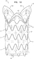
- Figs. 1A-B are schematic illustrations of a multi-component stent-graft system 10, in accordance with respective applications of the present invention.
- multi-component stent-graft system 10 is provided for treating an ascending aorta suffering from an aneurysm or a dissection (a Type A dissection).
- the system is configured to be deployed in the ascending aorta, aortic sinuses, and left and right coronary arteries.
- the multi-component stent-graft system defines blood-flow paths both through the ascending aorta and into the coronary arteries.
- Multi-component stent-graft system 10 comprises a generally tubular main stent-graft 20, and, typically, two generally tubular branching covered stents 22.
- the main stent-graft and covered stents are configured to assume radially-compressed states, such as when initially positioned in one or more delivery tools, and to assume radially-expanded states upon being deployed in respective target locations in vasculature of a subject.
- FIG. 1A-B show stent-graft 20 and branching covered stents 22 unconstrained in their radially-expanded states, i.e., no forces are applied to the stent-graft or the branching covered stents by a delivery tool, walls of a blood vessel, or otherwise.
- the stent-graft and branching covered stents are relaxed in their radially-expanded states.
- the stent-graft and branching covered stents are configured to be self-expanding. For example, they may be heat-set to assume their radially-expanded states.
- Stent-graft 20 has distal and proximal stent-graft ends 26 and 28.
- Stent-graft 20 comprises a generally tubular support element 30 and a covering element 32 that is attached to and at least partially covers (e.g., only partially covers) the support element.
- Support element 30 typically comprises a plurality of structural stent elements 31.
- structural stent elements 31 are arranged as a plurality of circumferential stent springs 33.
- support element 30 comprises a metal (such as an elastic metal, or stainless steel), a super-elastic alloy (such as Nitinol).
- Covering element 32 serves as a blood flow guide through at least a portion of the stent-graft.
- Covering element 32 typically comprises at least one biologically-compatible substantially blood-impervious flexible sheet, which is attached (such as by stitching) to at least a portion of the respective support element, on either side of the surfaces defined by the support element.
- the flexible sheet may comprise, for example, a polymeric material (e.g., polyester, or polytetrafluoroethylene), a textile material (e.g., polyethylene terephthalate (PET), or expanded polytetrafluoroethylene (ePTFE)), natural tissue (e.g., saphenous vein or collagen), or a combination thereof.
- a polymeric material e.g., polyester, or polytetrafluoroethylene
- textile material e.g., polyethylene terephthalate (PET), or expanded polytetrafluoroethylene (ePTFE)
- natural tissue e.g., saphenous vein or collagen
- a diameter D1 (labeled in Fig. 2A ) of stent-graft 20 is at least 30 mm, no more than 48 mm, and/or between 30 and 48 mm, such as at least 35 mm, no more than 45 mm, and/or between 35 and 45 mm, when stent-graft 20 is unconstrained in the radially-expanded state.
- Each of branching covered stents 22 comprises a generally tubular support element and a covering element that is attached to and at least partially covers (e.g., only partially covers) the support element.
- the support element typically comprises a plurality of structural stent elements.
- the structural stent elements are arranged as a plurality of circumferential stent springs.
- the support element comprises a metal (such as an elastic metal, or stainless steel), a super-elastic alloy (such as Nitinol).
- the covering element serves as a blood flow guide through at least a portion of the branching covered stent.
- the covering element typically comprises at least one biologically-compatible substantially blood-impervious flexible sheet, which is attached (such as by stitching) to at least a portion of the respective support element, on either side of the surfaces defined by the support element.
- the flexible sheet may comprise, for example, a polymeric material (e.g., polyester, or polytetrafluoroethylene), a textile material (e.g., polyethylene terephthalate (PET), or expanded polytetrafluoroethylene (ePTFE)), natural tissue (e.g., saphenous vein or collagen), or a combination thereof.
- Fig. 3 is a schematic illustration of a single proximally-extending piece 42, in accordance with an application of the present invention.
- a proximal end portion 40 of covering element 32 is shaped so as to define at least first and second proximally-extending pieces 42A and 42B.
- the proximally-extending pieces are configured to be positioned at least partially in the aortic sinuses so as to provide a proximal landing zone for stent-graft 20, such as described hereinbelow with reference to Fig. 9F .
- proximally-extending pieces 42 When stent-graft 20 is unconstrained in its radially-expanded state and proximally-extending pieces 42 are fully proximally extended, proximally-extending pieces 42 typically:
- base lengths L1 of first and second proximally-extending pieces 42A and 42B are each at least 30 mm, no more than 50 mm, and/or between 30 and 50 mm.
- first and second proximally-extending pieces 42A and 42B when fully proximally extended, have respective surface areas equal to at least 15% (such as at least 30%, no more than 150%, and/or between 15% (such as 30%) and 150% of the square of respective base lengths L1.
- the surface area of each of the proximally-extending pieces may be equal to at least 100 mm2, no more than 400 mm2, and/or between 100 and 400 mm2.
- an arc ⁇ (beta) (labeled in Fig.
- first and second proximally-extending pieces 42A and 42B have an angle of at least 5 degrees, no more than 50 degrees, and/or between 5 and 50 degrees, when stent-graft 20 is unconstrained in the radially-expanded state.
- first and second proximally-extending pieces 42A and 42B have substantially a same shape and size.
- first and second proximally-extending pieces 42A and 42B are shaped so as to define respective fenestrations 50 through covering element 32.
- each of fenestrations 50 has an area of at least 6 mm2, no more than 35 mm2, and/or between 6 and 35 mm2 when stent-graft 20 is unconstrained in the radially-expanded state and proximally-extending pieces 42 are fully proximally extended.
- First and second branching covered stents 22 (shown in Figs.
- each of fenestrations 50 is generally circular when the stent-graft is unconstrained in the radially-expanded state and the proximally-extending pieces are fully proximally extended.
- a diameter of each of fenestrations 50 may be at least 3 mm, no more than 8 mm, and/or between 3 and 8 mm, when stent-graft 20 is unconstrained in the radially-expanded state and proximally-extending pieces 42 are fully proximally extended.
- first proximally-extending piece 42A is attached to one or more of structural stent elements 31, and second proximally-extending piece 42B is attached to one or more of structural stent elements 31.
- first and second proximally-extending pieces 42A and 42B are attached to the same one or more structural elements 31, such as shown in Figs. 1A-B and 2A-C ; alternatively, they are attached to different ones of the structural elements (configuration not shown).
- structural stent elements 31 are attached such that at least a portion of the one or more of the structural stent elements is proximal to fenestrations 50 when stent-graft 20 is unconstrained in the radially-expanded state and proximally-extending pieces 42 are fully proximally extended.
- one or more of the structural stent elements may be attached along at least a portion of a proximal border of each of proximally-extending pieces 42A and 42B. These proximally-positioned structural stent elements may provide structure to the proximally-extending pieces, and may help anchor the proximally-extending pieces to the walls of the aortic sinuses.
- fenestrations 50 are circumferentially centered on respective proximally-extending pieces 42 when stent-graft 20 is unconstrained in the radially-expanded state and proximally-extending pieces 42 are fully proximally extended.
- respective closest distances D2 of fenestrations 50 to proximal-most portions 48 equal at least 10%, no more than 30%, and/or between 10% and 30% of respective axial lengths L2, when stent-graft 20 is unconstrained in the radially-expanded state and proximally-extending pieces 42 are fully proximally extended.
- stent-graft 20 further comprises at least one radiopaque wire 60 that is securely mounted around one of fenestrations 50, e.g., two radiopaque wires 60 that are securely mounted around respective fenestrations 50.
- Radiopaque wires 60 may facilitate proper positioning of fenestrations 50 with respect to the coronary ostia in the aortic sinuses, such as described hereinbelow with reference to Figs. 9D-E .
- the radiopaque wires may provide structural support to the borders of the fenestrations for good coupling with branching covered stents 22.
- non-radiopaque wires are instead provided around the fenestrations for providing such coupling without the radiopacity.
- first and the second proximally-extending pieces 42A and 42B are shaped so as to define respective scallops 70.
- Scallops 70 have respective axial lengths L3 measured from respective distal-most portions 72 of scallops 70 to respective proximal most-portions 48 of respective proximally-extending pieces 42, each of which axial lengths L3 is at least 7 mm, no more than 25 mm, and/or between 7 and 25 mm when stent-graft 20 is unconstrained in the radially-expanded state and proximally-extending pieces 42 are fully proximally extended.
- one or more of structural stent elements 31 are attached to each of first and second proximally-extending pieces 42A and 42B such that respective portions of at least one of the one or more of structural stent elements 31 traverse scallops 70 when stent-graft 20 is unconstrained in the radially-expanded state and the proximally-extending pieces are fully proximally extended.
- These traversing portions may serve to provide structure to the proximally-extending pieces and/or to provide elements to which branching covered stents 22 are securely coupled.
- one or more of structural stent elements 31 are attached to each of first and second proximally-extending pieces 42A and 42B such that respective portions of at least one of the one or more of structural stent elements 31 are disposed proximal to proximal most-portions 48 of proximally-extending pieces. These proximally-extending portions may help anchor the proximally-extending pieces to the walls of the aortic sinuses.
- first and second proximally-extending pieces 42A and 42B are shaped as first and second lobes 80 (labeled in Fig. 3 ), respectively, when stent-graft 20 is unconstrained in the radially-expanded state and proximally-extending pieces 42 are fully proximally extended.
- first and second lobes 80 are semicircular, when the stent-graft is unconstrained in the radially-expanded state and the lobes are fully proximally extended; for example, each of first and second semicircular lobes 80 may be shaped so as to circumscribe approximately 180 degrees of a circle, between 100 and 180 degrees of a circle (e.g., between 100 and 170 degrees of a circle), or between 180 to 270 degrees of a circle (e.g., between 190 and 270 degrees of a circle), when the stent-graft is unconstrained in the radially-expanded state and the lobes are fully proximally extended.
- proximal end portion 40 of covering element 32 is shaped so as to define a third proximally-extending piece 42C.
- third proximally-extending piece 42C When fully proximally extended, third proximally-extending piece 42C:
- first and second proximally-extending pieces 42A and 42B are shaped so as to define respective fenestrations 50
- third proximally-extending piece 42C is not shaped so as to define any fenestrations through covering element 32.
- Fig. 2C For some applications in which first and the second proximally-extending pieces 42A and 42B are shaped so as to define respective scallops 70, third proximally-extending piece 42C is not shaped so as to define any scallops.
- first, second, and third proximally-extending pieces 42A, 42B, and 42C have substantially a same shape and size, except that third proximally-extending piece 42C typically does not define a fenestration or scallop.
- one or more of the structural stent elements 31 are attached to third proximally-extending piece 42C, which may provide structure to the proximally-extending piece.
- proximally-extending pieces 42A, 42B, and/or 42C are outwardly convex (i.e., convex as viewed from outside the stent-graft) when stent-graft 20 is unconstrained in the radially-expanded state.
- convexity may facilitate good contact between the proximally-extending pieces and the walls of the aortic sinuses.
- proximally-extending pieces 42A, 42B, and/or 42C may be outwardly conically flared at an angle ⁇ (gamma) (labeled in Fig.
- ⁇ is at least 10 degrees, no more than 30 degrees, and/or between 10 and 30 degrees.
- proximally-extending pieces 42A, 42B, and/or 42C are not outwardly convex, e.g., generally conform to the tubular geometry of stent-graft 20, when stent-graft 20 is unconstrained in the radially-expanded state.
- stent-graft 20 further comprises one or more radiopaque markers 110, which are securely mounted to stent-graft 20 to distinguish between first and second proximally-extending pieces 42A and 42B.
- at least a first one 110A of radiopaque markers 110 is positioned on first proximally-extending piece 42A, and/or at least a second one 110B of radiopaque markers 110 is positioned on second proximally-extending piece 42B.
- first and second radiopaque markers 110A and 110B have different respective shapes.
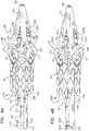
- Figs. 4A-B are schematic illustrations of components of a delivery tool, upon which stent-graft 20 is removably positioned, in accordance with respective applications of the present invention.
- Delivery tool 200 is configured to convey stent-graft 20 in the radially-compressed state to a target location in vasculature of a subject, and deploy the stent-graft at the target location, such as described hereinbelow with reference to Figs. 9A-J .
- Delivery tool 200 comprises at least one inner shaft 210 and an external sheath 212, described hereinbelow with reference to Figs. 7A-D .
- the at least one inner shaft 210 is shaped so as to define a primary bore 220 and first and second secondary bores 222A and 222B therethrough.
- stent-graft 20 is removably positioned such that distal stent-graft end 26 surrounds an axial portion 224 of the at least one inner shaft 210.
- Stent-graft 20 is shown in Figs. 4A and 4B in the radially-expanded state.
- the at least one inner shaft 210 comprises (a) a primary inner shaft 230, which is shaped so as to define primary bore 220 therethrough, and (b) first and second secondary inner shafts 232A and 232B, which are shaped so as to define first and second secondary bores 222A and 222B therethrough, respectively.
- first and second secondary inner shafts 232A and 232B which are shaped so as to define first and second secondary bores 222A and 222B therethrough, respectively.
- first and second secondary inner shafts 232A and 232B pass through first and second fenestrations 50, respectively, when stent-graft 20 is removably positioned such that first and second secondary inner shafts 232A and 232B extend proximally beyond proximal stent-graft end 28.
- a distal-to-proximal path along the secondary inner shafts passes from radially within to radially outside the proximally-extending pieces. This positioning of the secondary inner shafts enables the threading of secondary guidewires through fenestrations 50, as described hereinbelow with reference to Figs. 9A-B .
- first and second secondary inner shafts 232A and 232B pass through first and second scallops 70, respectively, when stent-graft 20 is removably positioned such that first and second secondary inner shafts 232A and 232B extend proximally beyond proximal stent-graft end 28 (configuration not shown).
- a distal-to-proximal path along the secondary inner shafts passes from radially within to radially outside the proximally-extending pieces. This positioning of the secondary inner shafts enables the threading of secondary guidewires through fenestrations 50, as described hereinbelow with reference to Figs. 9A-B .
- FIGS. 4A and 4B are schematic illustrations of a portion of primary inner shaft 230 and first and second secondary inner shafts 232A and 232B, in accordance with respective applications of the present invention.
- the configurations shown in Figs. 5A and 5B correspond with the configurations shown in Figs. 4A and 4B , respectively.
- a distal end portion 250 of the at least one inner shaft 210 is shaped so as to define primary bore 220 and first and second secondary bores 222A and 222B.
- the at least one inner shaft 210 trifurcates into primary inner shaft 230 and first and second secondary inner shafts 232A and 232B.
- the at least one inner shaft 210 along an entire length thereof, comprises separate primary inner shaft 230 and first and second secondary inner shafts 232A and 232B.
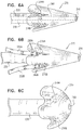
- Figs. 4A and 4B are schematic illustrations of a proximal tip 270 of delivery tool 200, in accordance with respective applications of the present invention.
- Proximal tip 270 is coupled to a proximal end portion of the at least one inner shaft 210, typically of primary inner shaft 230 when provided.
- Proximal tip 270 is configured to reduce potential damage to a blood vessel wall when the delivery tool is proximally translated relative to the vessel wall.
- proximal tip 270 is conically shaped, such that the tip has a smallest cross-sectional area at a proximal-most portion of the tip.
- the proximal tip is hemispherically shaped, such that the tip has a smallest cross-sectional area at a proximal-most portion of the tip.
- an external surface 274 of proximal tip 270 is shaped so as to define first and second grooves 276A and 276B.
- the grooves extend axially along at least an axial portion 278 of tip 270, and are shaped and sized so as to reversibly receive proximal end portions 280A and 280B of first and second secondary inner shafts 232A and 232B, respectively, such that proximal end portions 280A and 280B are disposed in the respective grooves.
- the grooves reach a distal end of proximal tip 270.
- the grooves taper from their distal ends toward their proximal ends.
- the grooves have (a) widths, measured circumferentially around the tip, approximately equal to an outer diameter of secondary inner shafts 232, and/or (b) depths equal to between 50% and 150% of the outer diameter of secondary inner shafts 232.
- external surface 274 of proximal tip 270 is shaped so as to define exactly one groove 276, such as for applications in which only a single secondary inner shaft 232 is provided.
- proximal tip 270 is shaped so as to define a tip bore 290 therethrough, and the tip bore and primary bore 220 are arranged axially continuously, such as shown in Fig. 6A .
- Figs. 7A-D are schematic illustrations of a portion of a deployment using delivery tool 200, in accordance with an application of the present invention.
- stent-graft 20 is removably positioned, while in the radially-compressed state, within external sheath 212, such that distal stent-graft end 26 surrounds axial portion 224 of the at least one inner shaft 210, as shown in Figs. 4A-B .
- grooves 276A and 276B and first and second inner shafts 232A and 232B are sized and shaped such that proximal end portions 280A and 280B of first and second secondary inner shafts 232A and 232B extend radially no more than does an external surface of external sheath 212, so as to provide smooth proximal advancement of the delivery tool through the vasculature.
- delivery tool 200 is configured such that axial translation of external sheath 212 (distally, to the left in Figs. 7B-D ) facilitates a transition of stent-graft 20 from the radially-compressed state to the radially-expanded state.
- grooves 276 and secondary inner shafts 232 are sized and shaped such that the secondary inner shafts rest in the grooves loosely enough to passively disengage with external sheath 212 is withdrawn, as shown in Fig. 7B .
- secondary inner shafts 232 are typically held in place in the grooves by external sheath 212, as shown in Fig. 7A .
- delivery tool 200 further comprises at least one stent-graft support member 292 that is securely fixed to an external surface of primary inner shaft 230, typically circumferentially disposed around the primary inner shaft.
- Stent-graft support member 292 is configured to prevent distal axial translation of stent-graft 20 as external sheath 212 is distally axially translated to facilitate the transition of stent-graft 20 from the radially-compressed state to the radially-expanded state, as described hereinabove with reference to Figs. 7A-D .
- stent-graft support member 292 is positioned proximally adjacent to proximal stent-graft end 28, when stent-graft 20 is removably positioned, while in the radially-compressed state, within external sheath 212 with proximal stent-graft end 28 surrounding the axial portion of primary inner shaft 230.
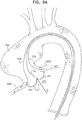
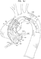
- Figs. 9A-K are schematic illustrations of an exemplary method, not part of the invention, of deploying stent-graft 20 and two branching covered stents 22 in an ascending aorta 300, using delivery tool 200, in accordance with an application of the present invention.
- the aorta is aneurysmatic, or the aortic wall may suffer from a dissection.
- a "lesion" of a blood vessel means an aneurysm and/or a dissection.
- a primary guidewire 310 and two secondary guidewires 312A and 312B are endovascularly (typically percutaneously) introduced into the vasculature at a vascular access site, such as a femoral artery or an iliac artery.
- the guidewires are advanced to ascending aorta 300, typically via the descending aorta.
- Primary guidewire 310 is typically advanced between leaflets 316 of an aortic valve 318 into a left ventricle 320.
- Secondary guidewires 312A and 312B are advanced into left and right coronary arteries 322A and 322B, respectively.
- primary guidewire 310 has a diameter of between 0.635 mm (0.025”) and 1.016 mm (0.04"), such as 0.889 mm (0.035”), and secondary guidewires 312 have a smaller diameter, such as between 0.254 mm (0.01”) and 0.508 mm (0.02”), e.g., 0.3556 mm (0.014").
- a distal end of primary guidewire 310 is threaded through tip bore 290 and primary bore 220, and respective distal ends of secondary guidewires 312A and 312B are threaded through first and second secondary bores 222A and 222B, respectively.
- secondary inner shafts 232A and 232B are kink-resistant, so that the secondary guidewires can be readily threaded through the secondary bores despite the radial compression of stent-graft 20 and the secondary inner shafts in external sheath 212. As shown in Fig.
- delivery tool 200 is advanced over the three guidewires into ascending aorta 300, while stent-graft 20 is removably positioned, while in the radially-compressed state, within external sheath 212 (stent-graft 20 is not visible in the sheath in Fig. 9B ).
- external sheath 212 is distally axially translated, so as to facilitate a partial transition of stent-graft 20 from the radially-compressed state to the radially-expanded state.
- first and second secondary inner shafts 232A and 232B pass through first and second fenestrations 50, as do secondary guidewires 312A and 312B, which pass through the secondary inner shafts, respectively.
- Stent-graft support member 292 if provided, prevents distal axial translation of stent-graft 20 as external sheath 212 is distally translated.
- secondary guidewires 312A and 312B guide respective fenestrations 50 of proximally-extending pieces 42A and 42B to respective left and right coronary ostia 330A and 330B, and align the fenestrations with the ostia.
- Such alignment facilitates the deployment of branching covered stents 22 in coronary arteries 322A and 322B, as described hereinbelow with reference to Fig. 9K .
- Proximal tip 270 may be advanced through leaflets 316 of aortic valve 318 into left ventricle 320, which may improve the stabilization of the delivery system while deploying the stent grafts and covered branching stents.
- secondary guidewires 312A and 312B guide respective scallops 70 of proximally-extending pieces 42A and 42B to respective left and right coronary ostia 330A and 330B, and align the scallops with the ostia.
- proximally-extending pieces 42A and 42B, as well as third proximally-extending piece 42C, if provided, are positioned at least partially in aortic sinuses 332, respectively, so as to provide a proximal landing zone for stent-graft 20.
- a relatively long landing zone of blood vessel wall is desirable to provide good anchoring and sealing in the ascending aorta, because the ascending aorta is highly motile and pulsatile.
- Proximal-most portions 48 of proximally-extending pieces 42A and 42B, and of third proximally-extending piece 42C if provided, are positioned in aortic sinuses 332, respectively.
- Proximal-most portions 48 of proximally-extending pieces 42A and 42B may touch the sinus floors at respective bases of leaflets 316.
- Fenestrations 50 are aligned with coronary ostia 330, or for configurations of stent-graft 20 in which proximally-extending pieces 42 are shaped so as to define scallops 70, such as described hereinabove with reference to Fig. 2C , the scallops are aligned with coronary ostia 330.
- delivery tool 200 is withdrawn from ascending aorta 300 and the patient's vasculature, typically leaving at least secondary guidewires 312A and 312B in place, extending into the coronary arteries.
- branching covered stents 22 are deployed, typically over secondary guidewires 312A and 312B, into coronary arteries 322A and 322B.
- Branching covered stents 22 are coupled to stent-graft 20 so as to form blood-impervious seals with respective fenestrations 50.
- the coupling may be performed using stent-graft coupling techniques known in the art and/or described in PCT Publications WO 2011/007354 , WO 2011/064782 , and/or WO 2013/005207 , all of which are assigned to the assignee of the present application.
- proximally-extending pieces 42 are shaped so as to define scallops 70, such as described hereinabove with reference to Fig. 2C
- branching covered stents 22 are coupled to stent-graft 20 so as to form blood-impervious seals with the partial borders of the scallops, respectively.
- Fig. 9K shows stent-graft 20 fully implanted in ascending aorta 300 and branching covered stents 22 fully implanted in left and right coronary arteries 322A and 322B.
- Stent-graft 20 and branching covered stents 22 together provide blood-flow paths (a) through ascending aorta 300, bypassing the aneurysm or the dissection, and (b) to left and right coronary arteries 322A and 322B.
- the coronary arteries typically provide stability to the branching covered stents.
- a "fenestration” is an opening entirely surrounded by a covering element.
- scallops 70 described hereinabove with reference to Fig. 2C , are not fenestrations, because the scallops are open to the proximal ends of the proximally-extending pieces and thus are not surrounded by the covering element.
- tubular means having the form of an elongated hollow object that defines a conduit therethrough.
- a “tubular” structure may have varied cross-sections therealong, and the cross-sections are not necessarily circular.
- one or more of the cross-sections may be generally circular, or generally elliptical but not circular, or circular.
- first and second secondary inner shafts 232A and 232B typically pass through first and second fenestrations 50 while stent-graft 20 is radially compressed within external sheath 212. It is also noted that in these applications, as well as the other applications described herein, first and second secondary inner shafts 232A and 232B typically do not contain any stent-grafts.
Landscapes
- Health & Medical Sciences (AREA)
- Engineering & Computer Science (AREA)
- Biomedical Technology (AREA)
- Cardiology (AREA)
- Oral & Maxillofacial Surgery (AREA)
- Transplantation (AREA)
- Heart & Thoracic Surgery (AREA)
- Vascular Medicine (AREA)
- Life Sciences & Earth Sciences (AREA)
- Animal Behavior & Ethology (AREA)
- General Health & Medical Sciences (AREA)
- Public Health (AREA)
- Veterinary Medicine (AREA)
- Gastroenterology & Hepatology (AREA)
- Pulmonology (AREA)
- Prostheses (AREA)
Claims (14)
- Vorrichtung, die ein generell röhrenförmiges Stenttransplantat (20) beinhaltet, das ein distales und proximales Stenttransplantatende (26, 28) aufweist und Folgendes beinhaltet:ein generell röhrenförmiges Stützelement (30), das eine Vielzahl von strukturellen Stentelementen (31) beinhaltet; undein Abdeckelement (32), das am Stützelement (30) angebracht ist und dieses mindestens teilweise abdeckt,wobei, wenn das Stenttransplantat (20) in einem radial expandierten Zustand ungebunden ist, ein proximaler Endabschnitt (40) des Abdeckelements (32) so geformt ist, dass mindestens ein erstes und zweites sich proximal erstreckendes Stück (42A, 42B) definiert wird,wobei, wenn das Stenttransplantat (20) im radial expandierten Zustand ungebunden ist und die sich proximal erstreckenden Stücke (42A, 42B) vollständig proximal erstreckt sind, die sich proximal erstreckenden Stücke (42A, 42B):so geformt sind, dass jeweilige distale Basen (46) definiert werden, die (a) jeweilige Basislängen (L1) aufweisen, umlaufend um das Stenttransplantat (20) gemessen, und (b) umlaufend jeweilige Basisbögen (α) abgrenzen, wobei jeder Basisbogen (α) einen Winkel zwischen 100 und 140 Grad aufweist,so geformt sind, dass jeweilige proximalste Abschnitte (48) definiert werden, die proximaler sind als alle anderen jeweiligen Abschnitte des Abdeckelements (32), die die jeweiligen Basisbögen (α) abgrenzen, undjeweilige Axiallängen (L2) aufweisen, axial zwischen den jeweiligen distalen Basen (46) und den jeweiligen proximalsten Abschnitten (48) gemessen, wobei die Längen (L2) zwischen 50 % und 150 % den jeweiligen Basislängen (L1) gleichen, undwobei, wenn das Stenttransplantat (20) im radial expandierten Zustand ungebunden ist und die sich proximal erstreckenden Stücke (42A, 42B) vollständig proximal erstreckt sind, das erste und zweite sich proximal erstreckende Stück (42A, 42B) so geformt sind, dass eine erste und zweite Fenestration (50) durch das Abdeckelement (32) definiert wird, wobei jede Fenestration (50) eine Fläche von mindestens 6 mm2 aufweist,wobei die Vorrichtung ferner ein Zustellwerkzeug (200) beinhaltet, das (a) konfiguriert ist, um das Stenttransplantat (20) im radial komprimierten Zustand an eine Zielstelle in der Vaskulatur eines Subjekts zu befördern und das Stenttransplantat (20) an der Zielstelle zu entfalten, und (b) Folgendes beinhaltet:einen primären Innenschaft (230), der so geformt ist, dass eine primäre Bohrung (220) definiert wird;einen ersten und zweiten, sekundären Innenschaft (232A, 232B), die so geformt sind, dass eine erste bzw. zweite, sekundäre Bohrung (222A, 222B) durch diese definiert wird; undeine externe Umhüllung (212), undwobei das Zustellwerkzeug (200) konfiguriert ist, sodass axiale Translation der externen Umhüllung (212) einen Übergang des Stenttransplantats (20) vom radial komprimierten Zustand zum radial expandierten Zustand erleichtert,dadurch gekennzeichnet, dass das Stenttransplantat (20) innerhalb der externen Umhüllung (212) entfernbar positioniert ist, während es im radial komprimierten Zustand ist, sodass:(a) das distale Stenttransplantatende (26) jeweilige axiale Abschnitte (224) des primären Innenschafts (230) und des ersten und des zweiten sekundären Innenschafts (232A, 232B) umgibt,(b) das proximale Stenttransplantatende (28) einen axialen Abschnitt (238) des primären Innenschafts (230) umgibt und(c) sich der erste und der zweite sekundäre Innenschaft (232A, 232B) proximal über das proximale Stenttransplantatende (28) hinaus erstrecken und durch die erste bzw. die zweite Fenestration (50) hindurch gehen.
- Vorrichtung gemäß Anspruch 1, wobei die sich proximal erstreckenden Stücke (42A, 42B) in einem Winkel zwischen 10 und 30 Grad zu einer zentralen Längsachse (20) nach außen konisch aufgeweitet sind, wenn das Stenttransplantat (20) im radial expandierten Zustand ungebunden ist und die sich proximal erstreckenden Stücke (42A, 42B) vollständig proximal erstreckt werden.
- Vorrichtung gemäß einem der Ansprüche 1-2, die ein Mehrkomponenten-Stenttransplantatsystem (10) beinhaltet, das Folgendes beinhaltet:das Stenttransplantat (20); undeinen ersten und zweiten verzweigten, abgedeckten Stent (22), die jeweilige Endabschnitte (52) aufweisen, die bemessen und konfiguriert sind, um blutundurchlässige Dichtungen mit der ersten und der zweiten Fenestration (50) des ersten bzw. des zweiten sich proximal erstreckenden Stückes (42A, 42B) des Stenttransplantats (20) zu bilden.
- Vorrichtung gemäß einem der Ansprüche 1-2, wobei jede der ersten und der zweiten Fenestration (50) eine Fläche von nicht mehr als 35 mm2 aufweist, wenn das Stenttransplantat (20) im radial expandierten Zustand ungebunden ist und die sich proximal erstreckenden Stücke (42A, 42B) vollständig proximal erstreckt sind.
- Vorrichtung gemäß einem der Ansprüche 1-2, wobei das erste und das zweite sich proximal erstreckende Stück (42A, 42B) als erster bzw. zweiter Lappen geformt sind, wenn das Stenttransplantat (20) im radial expandierten Zustand ungebunden ist und die sich proximal erstreckenden Stücke (42A, 42B) vollständig proximal erstreckt sind.
- Vorrichtung gemäß einem der Ansprüche 1-2,
wobei, wenn das Stenttransplantat (20) im radial expandierten Zustand ungebunden ist, der proximale Endabschnitt (40) des Abdeckelements (32) so geformt ist, dass ein drittes sich proximal erstreckende Stück (42C) definiert wird, und
wobei, wenn das Stenttransplantat (20) im radial expandierten Zustand ungebunden ist und das dritte sich proximal erstreckende Stück (42C) vollständig proximal erstreckt ist, das dritte sich proximal erstreckende Stück (42C):so geformt ist, dass eine dritte distale Basis (90) definiert wird, die (a) eine dritte Basislänge aufweist, umlaufend um das Stenttransplantat (20) gemessen, und (b) umlaufend einen dritten Basisbogen abgrenzt, wobei der dritte Basisbogen einen Winkel zwischen 100 und 140 Grad aufweist,so geformt ist, dass ein dritter proximalster Abschnitt (92) definiert wird, der proximaler ist als alle anderen jeweiligen Abschnitte des Abdeckelements (32), die den dritten Basisbogen abgrenzen, undeine dritte Axiallänge aufweist, axial zwischen der dritten distalen Basis (90) und dem dritten proximalsten Abschnitt (92) gemessen, wobei die Länge zwischen 50 % und 150 % der dritten Basislänge gleicht. - Vorrichtung gemäß Anspruch 6, wobei das dritte sich proximal erstreckende Stück (42C) nicht so geformt ist, dass Fenestrationen durch das Abdeckelement (32) definiert werden.
- Vorrichtung gemäß einem der Ansprüche 1-2,
wobei das Zustellwerkzeug (200) ferner eine proximale Spitze (270) beinhaltet, die mit einem proximalen Endabschnitt des primären Innenschafts (230) gekoppelt ist, und
wobei eine externe Oberfläche der proximalen Spitze (270) so geformt ist, dass eine erste und zweite Rille (276A, 276B) gebildet wird, die sich (a) axial entlang mindestens einem axialen Abschnitt der Spitze (270) erstrecken, und (b) so geformt und bemessen sind, um reversibel jeweilige proximale Endabschnitte (280A, 280B) des ersten und des zweiten sekundären Innenschafts (232A, 232B) aufzunehmen. - Vorrichtung gemäß einem der Ansprüche 1-2, wobei das Zustellwerkzeug (200) ferner mindestens ein Stenttransplantat-Stützglied (292) beinhaltet, das sicher an einer externen Oberfläche des primären Innenschafts (230) fixiert ist und das konfiguriert ist, um distale axiale Translation des Stenttransplantats (20) zu verhindern, wenn die externe Umhüllung (212) distal axial translatiert wird, um den Übergang des Stenttransplantats (20) vom radial komprimierten Zustand zum radial expandierten Zustand zu erleichtern.
- Vorrichtung gemäß Anspruch 9, wobei das Stenttransplantat-Stützglied (292) umlaufend um den primären Innenschaft (230) angeordnet ist.
- Vorrichtung gemäß Anspruch 9, wobei das Stenttransplantat-Stützglied (292) proximal neben dem proximalen Stenttransplantatende (28) positioniert ist, wenn das Stenttransplantat (20) innerhalb der externen Umhüllung (212) entfernbar positioniert ist, während es im radial komprimierten Zustand ist, mit dem proximalen Stenttransplantatende (28) den axialen Abschnitt (238) des primären Innenschafts (230) umgebend.
- Vorrichtung gemäß einem der Ansprüche 1-2, wobei das Zustellwerkzeug (200) ferner eine proximale Spitze (270) beinhaltet, die mit einem proximalen Endabschnitt des primären Innenschafts (230) gekoppelt ist.
- Vorrichtung gemäß Anspruch 12, wobei die proximale Spitze (270) konisch geformt ist, sodass die Spitze (270) eine kleinste Querschnittsfläche an einem proximalsten Abschnitt der Spitze (270) aufweist.
- Vorrichtung gemäß Anspruch 12, wobei die proximale Spitze (270) halbkugelförmig geformt ist, sodass die Spitze (270) eine kleinste Querschnittsfläche an einem proximalsten Abschnitt der Spitze (270) aufweist.
Applications Claiming Priority (2)
| Application Number | Priority Date | Filing Date | Title |
|---|---|---|---|
| US201361826544P | 2013-05-23 | 2013-05-23 | |
| PCT/IL2014/050434 WO2014188412A2 (en) | 2013-05-23 | 2014-05-18 | Ascending aorta stent-graft system |
Publications (3)
| Publication Number | Publication Date |
|---|---|
| EP2999429A2 EP2999429A2 (de) | 2016-03-30 |
| EP2999429A4 EP2999429A4 (de) | 2016-11-30 |
| EP2999429B1 true EP2999429B1 (de) | 2018-07-04 |
Family
ID=51934276
Family Applications (1)
| Application Number | Title | Priority Date | Filing Date |
|---|---|---|---|
| EP14801036.6A Active EP2999429B1 (de) | 2013-05-23 | 2014-05-18 | Aufsteigendes aorta-stentimplantatsystem |
Country Status (4)
| Country | Link |
|---|---|
| US (1) | US20160193029A1 (de) |
| EP (1) | EP2999429B1 (de) |
| CN (1) | CN105407836B (de) |
| WO (1) | WO2014188412A2 (de) |
Cited By (2)
| Publication number | Priority date | Publication date | Assignee | Title |
|---|---|---|---|---|
| US10888414B2 (en) | 2019-03-20 | 2021-01-12 | inQB8 Medical Technologies, LLC | Aortic dissection implant |
| US11324583B1 (en) | 2021-07-06 | 2022-05-10 | Archo Medical LTDA | Multi-lumen stent-graft and related surgical methods |
Families Citing this family (24)
| Publication number | Priority date | Publication date | Assignee | Title |
|---|---|---|---|---|
| WO2010150208A2 (en) | 2009-06-23 | 2010-12-29 | Endospan Ltd. | Vascular prostheses for treating aneurysms |
| US9839510B2 (en) | 2011-08-28 | 2017-12-12 | Endospan Ltd. | Stent-grafts with post-deployment variable radial displacement |
| WO2013065040A1 (en) | 2011-10-30 | 2013-05-10 | Endospan Ltd. | Triple-collar stent-graft |
| WO2013084235A2 (en) | 2011-12-04 | 2013-06-13 | Endospan Ltd. | Branched stent-graft system |
| WO2013171730A1 (en) | 2012-05-15 | 2013-11-21 | Endospan Ltd. | Stent-graft with fixation elements that are radially confined for delivery |
| WO2014108895A2 (en) | 2013-01-08 | 2014-07-17 | Endospan Ltd. | Minimization of stent-graft migration during implantation |
| US9668892B2 (en) | 2013-03-11 | 2017-06-06 | Endospan Ltd. | Multi-component stent-graft system for aortic dissections |
| US9861474B2 (en) | 2013-07-18 | 2018-01-09 | The Trustees Of The University Of Pennsylvania | Cardiac repair prosthesis sets and methods |
| WO2015075708A1 (en) | 2013-11-19 | 2015-05-28 | Endospan Ltd. | Stent system with radial-expansion locking |
| US10485684B2 (en) | 2014-12-18 | 2019-11-26 | Endospan Ltd. | Endovascular stent-graft with fatigue-resistant lateral tube |
| CA3074918C (en) | 2015-01-11 | 2023-08-08 | Ascyrus Medical, Llc | Hybrid device for surgical aortic repair and method of using the same |
| CN107205811B (zh) | 2015-01-12 | 2019-06-25 | 恩都思潘有限公司 | 自弯曲的支架移植物 |
| US20180021157A1 (en) | 2015-02-02 | 2018-01-25 | Endospan Ltd. | Self-orienting endovascular delivery system |
| WO2017081679A1 (en) | 2015-11-12 | 2017-05-18 | Endospan Ltd. | Stent-grafts systems with skirt |
| GB201622215D0 (en) | 2016-12-23 | 2017-02-08 | Tonkin Liu Stents Ltd | Expanding device |
| CN106726038B (zh) * | 2017-01-23 | 2018-05-25 | 中国人民解放军第二军医大学 | 一种升主动脉腔内隔绝移植装置 |
| JP2020512914A (ja) | 2017-03-21 | 2020-04-30 | エンドスパン リミテッド | 外部擾乱の周りを密封するためのステントグラフト |
| US20200237496A1 (en) * | 2017-07-25 | 2020-07-30 | KHOYNEZHAD, Ali | Endovascular replacement of aortic valve, aortic root, and ascending aorta |
| EP3449871A3 (de) * | 2017-09-01 | 2019-06-12 | Cook Medical Technologies LLC | Endoluminale prothese mit einer aortensinusstentanordnung |
| WO2019205599A1 (zh) * | 2018-04-25 | 2019-10-31 | 上海长海医院 | 升主动脉支架移植物 |
| IT201800006821A1 (it) * | 2018-06-29 | 2019-12-29 | Felice Pecoraro | Strumento medico per inserimenti intraluminali |
| WO2020126001A1 (de) | 2018-12-20 | 2020-06-25 | Medizinische Universität Wien | Stentgraft und vorrichtung zum zuführen und setzen eines solchen stentgrafts in die aorta ascendens |
| WO2024057320A1 (en) | 2022-09-15 | 2024-03-21 | Endospan Ltd. | Double-branching ascending aortic stent-graft systems |
| GB2623515A (en) * | 2022-10-17 | 2024-04-24 | Cook Medical Technologies Llc | Stent graft assembly |
Family Cites Families (19)
| Publication number | Priority date | Publication date | Assignee | Title |
|---|---|---|---|---|
| US6596020B2 (en) * | 1996-11-04 | 2003-07-22 | Advanced Stent Technologies, Inc. | Method of delivering a stent with a side opening |
| US7628803B2 (en) * | 2001-02-05 | 2009-12-08 | Cook Incorporated | Implantable vascular device |
| US6544285B1 (en) * | 2000-01-17 | 2003-04-08 | Heinemen Medical Research, Inc. | Aortic root prosthesis with compliant sinuses |
| US7018404B2 (en) * | 2002-01-24 | 2006-03-28 | St. Jude Medical, Inc. | Conduit for aorta or pulmonary artery replacement |
| US7550004B2 (en) * | 2002-08-20 | 2009-06-23 | Cook Biotech Incorporated | Endoluminal device with extracellular matrix material and methods |
| US7763063B2 (en) * | 2003-09-03 | 2010-07-27 | Bolton Medical, Inc. | Self-aligning stent graft delivery system, kit, and method |
| DE602005005495T2 (de) * | 2004-09-02 | 2009-04-16 | Med Institute, Inc., West Lafayette | Modulare prothese und verfahren für verzweigte gefässe |
| US7914574B2 (en) * | 2005-08-02 | 2011-03-29 | Reva Medical, Inc. | Axially nested slide and lock expandable device |
| US9757260B2 (en) * | 2006-03-30 | 2017-09-12 | Medtronic Vascular, Inc. | Prosthesis with guide lumen |
| GB0803302D0 (en) * | 2008-02-22 | 2008-04-02 | Barts & London Nhs Trust | Blood vessel prosthesis and delivery apparatus |
| US20090264993A1 (en) * | 2008-04-18 | 2009-10-22 | Medtronic Vascular, Inc. | Endovascular Prosthesis for Ascending Aorta |
| JP5509491B2 (ja) * | 2009-03-26 | 2014-06-04 | クック メディカル テクノロジーズ エルエルシー | ステントグラフト |
| WO2010127040A1 (en) * | 2009-04-28 | 2010-11-04 | Endologix, Inc. | Apparatus and method of placement of a graft or graft system |
| US8795354B2 (en) * | 2010-03-05 | 2014-08-05 | Edwards Lifesciences Corporation | Low-profile heart valve and delivery system |
| WO2011122444A1 (ja) * | 2010-03-30 | 2011-10-06 | テルモ株式会社 | ステントデリバリーシステム |
| US8864811B2 (en) * | 2010-06-08 | 2014-10-21 | Veniti, Inc. | Bi-directional stent delivery system |
| US8870939B2 (en) * | 2010-08-21 | 2014-10-28 | Cook Medical Technologies Llc | Prosthesis having pivoting fenestration |
| CN103547238B (zh) * | 2011-04-27 | 2016-01-20 | 百乐仕医疗器械有限公司 | 支架 |
| EP3053545B1 (de) * | 2011-04-28 | 2019-09-18 | Cook Medical Technologies LLC | Vorrichtung zur ermöglichung des einsetzens einer endoluminalen prothese |
-
2014
- 2014-05-18 US US14/893,201 patent/US20160193029A1/en not_active Abandoned
- 2014-05-18 WO PCT/IL2014/050434 patent/WO2014188412A2/en active Application Filing
- 2014-05-18 CN CN201480041652.8A patent/CN105407836B/zh active Active
- 2014-05-18 EP EP14801036.6A patent/EP2999429B1/de active Active
Non-Patent Citations (1)
| Title |
|---|
| None * |
Cited By (2)
| Publication number | Priority date | Publication date | Assignee | Title |
|---|---|---|---|---|
| US10888414B2 (en) | 2019-03-20 | 2021-01-12 | inQB8 Medical Technologies, LLC | Aortic dissection implant |
| US11324583B1 (en) | 2021-07-06 | 2022-05-10 | Archo Medical LTDA | Multi-lumen stent-graft and related surgical methods |
Also Published As
| Publication number | Publication date |
|---|---|
| EP2999429A4 (de) | 2016-11-30 |
| CN105407836B (zh) | 2018-10-02 |
| WO2014188412A2 (en) | 2014-11-27 |
| EP2999429A2 (de) | 2016-03-30 |
| US20160193029A1 (en) | 2016-07-07 |
| CN105407836A (zh) | 2016-03-16 |
| WO2014188412A3 (en) | 2015-01-22 |
Similar Documents
| Publication | Publication Date | Title |
|---|---|---|
| EP2999429B1 (de) | Aufsteigendes aorta-stentimplantatsystem | |
| US10888413B2 (en) | Multi-component stent-graft system for implantation in a blood vessel with multiple branches | |
| US9597204B2 (en) | Branched stent-graft system | |
| US10952884B2 (en) | Multi-fabric endovascular stent-graft | |
| EP2967830B1 (de) | Mehrteiliges stent-transplantatsystem für aorta-dissektionen | |
| US20160157990A1 (en) | Endovascular fenestrated stent-grafting | |
| EP2509535B1 (de) | Endovaskuläres stentpfropfsystem mit perforierten und querlaufenden stentpfropfen | |
| EP2579811B1 (de) | Endovaskuläres system mit rundum überlappenden stent-pfropfen | |
| US20120310324A1 (en) | Treatment of a main body lumen in the vicinity of a branching body lumen | |
| EP3244828B1 (de) | Selbstkrümmendes stenttransplantat | |
| US11389313B2 (en) | Self-orienting endovascular delivery system | |
| EP3150167A1 (de) | Modulares system mit mindestens einem astgraft |
Legal Events
| Date | Code | Title | Description |
|---|---|---|---|
| PUAI | Public reference made under article 153(3) epc to a published international application that has entered the european phase |
Free format text: ORIGINAL CODE: 0009012 |
|
| 17P | Request for examination filed |
Effective date: 20151203 |
|
| AK | Designated contracting states |
Kind code of ref document: A2 Designated state(s): AL AT BE BG CH CY CZ DE DK EE ES FI FR GB GR HR HU IE IS IT LI LT LU LV MC MK MT NL NO PL PT RO RS SE SI SK SM TR |
|
| AX | Request for extension of the european patent |
Extension state: BA ME |
|
| DAX | Request for extension of the european patent (deleted) | ||
| A4 | Supplementary search report drawn up and despatched |
Effective date: 20161027 |
|
| RIC1 | Information provided on ipc code assigned before grant |
Ipc: A61F 2/90 20130101ALI20161021BHEP Ipc: A61F 2/66 20060101ALI20161021BHEP Ipc: A61F 2/06 20060101AFI20161021BHEP Ipc: A61F 2/07 20130101ALI20161021BHEP |
|
| GRAP | Despatch of communication of intention to grant a patent |
Free format text: ORIGINAL CODE: EPIDOSNIGR1 |
|
| STAA | Information on the status of an ep patent application or granted ep patent |
Free format text: STATUS: GRANT OF PATENT IS INTENDED |
|
| INTG | Intention to grant announced |
Effective date: 20180103 |
|
| GRAS | Grant fee paid |
Free format text: ORIGINAL CODE: EPIDOSNIGR3 |
|
| GRAJ | Information related to disapproval of communication of intention to grant by the applicant or resumption of examination proceedings by the epo deleted |
Free format text: ORIGINAL CODE: EPIDOSDIGR1 |
|
| GRAL | Information related to payment of fee for publishing/printing deleted |
Free format text: ORIGINAL CODE: EPIDOSDIGR3 |
|
| STAA | Information on the status of an ep patent application or granted ep patent |
Free format text: STATUS: REQUEST FOR EXAMINATION WAS MADE |
|
| GRAR | Information related to intention to grant a patent recorded |
Free format text: ORIGINAL CODE: EPIDOSNIGR71 |
|
| STAA | Information on the status of an ep patent application or granted ep patent |
Free format text: STATUS: GRANT OF PATENT IS INTENDED |
|
| GRAC | Information related to communication of intention to grant a patent modified |
Free format text: ORIGINAL CODE: EPIDOSCIGR1 |
|
| GRAJ | Information related to disapproval of communication of intention to grant by the applicant or resumption of examination proceedings by the epo deleted |
Free format text: ORIGINAL CODE: EPIDOSDIGR1 |
|
| GRAL | Information related to payment of fee for publishing/printing deleted |
Free format text: ORIGINAL CODE: EPIDOSDIGR3 |
|
| GRAP | Despatch of communication of intention to grant a patent |
Free format text: ORIGINAL CODE: EPIDOSNIGR1 |
|
| GRAA | (expected) grant |
Free format text: ORIGINAL CODE: 0009210 |
|
| STAA | Information on the status of an ep patent application or granted ep patent |
Free format text: STATUS: THE PATENT HAS BEEN GRANTED |
|
| INTC | Intention to grant announced (deleted) | ||
| INTG | Intention to grant announced |
Effective date: 20180522 |
|
| AK | Designated contracting states |
Kind code of ref document: B1 Designated state(s): AL AT BE BG CH CY CZ DE DK EE ES FI FR GB GR HR HU IE IS IT LI LT LU LV MC MK MT NL NO PL PT RO RS SE SI SK SM TR |
|
| REG | Reference to a national code |
Ref country code: GB Ref legal event code: FG4D |
|
| REG | Reference to a national code |
Ref country code: CH Ref legal event code: EP |
|
| REG | Reference to a national code |
Ref country code: AT Ref legal event code: REF Ref document number: 1013696 Country of ref document: AT Kind code of ref document: T Effective date: 20180715 |
|
| REG | Reference to a national code |
Ref country code: IE Ref legal event code: FG4D |
|
| REG | Reference to a national code |
Ref country code: DE Ref legal event code: R096 Ref document number: 602014027979 Country of ref document: DE |
|
| REG | Reference to a national code |
Ref country code: NL Ref legal event code: FP |
|
| REG | Reference to a national code |
Ref country code: LT Ref legal event code: MG4D |
|
| REG | Reference to a national code |
Ref country code: AT Ref legal event code: MK05 Ref document number: 1013696 Country of ref document: AT Kind code of ref document: T Effective date: 20180704 |
|
| PG25 | Lapsed in a contracting state [announced via postgrant information from national office to epo] |
Ref country code: AT Free format text: LAPSE BECAUSE OF FAILURE TO SUBMIT A TRANSLATION OF THE DESCRIPTION OR TO PAY THE FEE WITHIN THE PRESCRIBED TIME-LIMIT Effective date: 20180704 Ref country code: BG Free format text: LAPSE BECAUSE OF FAILURE TO SUBMIT A TRANSLATION OF THE DESCRIPTION OR TO PAY THE FEE WITHIN THE PRESCRIBED TIME-LIMIT Effective date: 20181004 Ref country code: PL Free format text: LAPSE BECAUSE OF FAILURE TO SUBMIT A TRANSLATION OF THE DESCRIPTION OR TO PAY THE FEE WITHIN THE PRESCRIBED TIME-LIMIT Effective date: 20180704 Ref country code: IS Free format text: LAPSE BECAUSE OF FAILURE TO SUBMIT A TRANSLATION OF THE DESCRIPTION OR TO PAY THE FEE WITHIN THE PRESCRIBED TIME-LIMIT Effective date: 20181104 Ref country code: SE Free format text: LAPSE BECAUSE OF FAILURE TO SUBMIT A TRANSLATION OF THE DESCRIPTION OR TO PAY THE FEE WITHIN THE PRESCRIBED TIME-LIMIT Effective date: 20180704 Ref country code: FI Free format text: LAPSE BECAUSE OF FAILURE TO SUBMIT A TRANSLATION OF THE DESCRIPTION OR TO PAY THE FEE WITHIN THE PRESCRIBED TIME-LIMIT Effective date: 20180704 Ref country code: NO Free format text: LAPSE BECAUSE OF FAILURE TO SUBMIT A TRANSLATION OF THE DESCRIPTION OR TO PAY THE FEE WITHIN THE PRESCRIBED TIME-LIMIT Effective date: 20181004 Ref country code: GR Free format text: LAPSE BECAUSE OF FAILURE TO SUBMIT A TRANSLATION OF THE DESCRIPTION OR TO PAY THE FEE WITHIN THE PRESCRIBED TIME-LIMIT Effective date: 20181005 Ref country code: RS Free format text: LAPSE BECAUSE OF FAILURE TO SUBMIT A TRANSLATION OF THE DESCRIPTION OR TO PAY THE FEE WITHIN THE PRESCRIBED TIME-LIMIT Effective date: 20180704 Ref country code: CZ Free format text: LAPSE BECAUSE OF FAILURE TO SUBMIT A TRANSLATION OF THE DESCRIPTION OR TO PAY THE FEE WITHIN THE PRESCRIBED TIME-LIMIT Effective date: 20180704 Ref country code: LT Free format text: LAPSE BECAUSE OF FAILURE TO SUBMIT A TRANSLATION OF THE DESCRIPTION OR TO PAY THE FEE WITHIN THE PRESCRIBED TIME-LIMIT Effective date: 20180704 |
|
| PG25 | Lapsed in a contracting state [announced via postgrant information from national office to epo] |
Ref country code: HR Free format text: LAPSE BECAUSE OF FAILURE TO SUBMIT A TRANSLATION OF THE DESCRIPTION OR TO PAY THE FEE WITHIN THE PRESCRIBED TIME-LIMIT Effective date: 20180704 Ref country code: AL Free format text: LAPSE BECAUSE OF FAILURE TO SUBMIT A TRANSLATION OF THE DESCRIPTION OR TO PAY THE FEE WITHIN THE PRESCRIBED TIME-LIMIT Effective date: 20180704 Ref country code: LV Free format text: LAPSE BECAUSE OF FAILURE TO SUBMIT A TRANSLATION OF THE DESCRIPTION OR TO PAY THE FEE WITHIN THE PRESCRIBED TIME-LIMIT Effective date: 20180704 Ref country code: ES Free format text: LAPSE BECAUSE OF FAILURE TO SUBMIT A TRANSLATION OF THE DESCRIPTION OR TO PAY THE FEE WITHIN THE PRESCRIBED TIME-LIMIT Effective date: 20180704 |
|
| REG | Reference to a national code |
Ref country code: DE Ref legal event code: R097 Ref document number: 602014027979 Country of ref document: DE |
|
| PG25 | Lapsed in a contracting state [announced via postgrant information from national office to epo] |
Ref country code: RO Free format text: LAPSE BECAUSE OF FAILURE TO SUBMIT A TRANSLATION OF THE DESCRIPTION OR TO PAY THE FEE WITHIN THE PRESCRIBED TIME-LIMIT Effective date: 20180704 Ref country code: EE Free format text: LAPSE BECAUSE OF FAILURE TO SUBMIT A TRANSLATION OF THE DESCRIPTION OR TO PAY THE FEE WITHIN THE PRESCRIBED TIME-LIMIT Effective date: 20180704 |
|
| PLBE | No opposition filed within time limit |
Free format text: ORIGINAL CODE: 0009261 |
|
| STAA | Information on the status of an ep patent application or granted ep patent |
Free format text: STATUS: NO OPPOSITION FILED WITHIN TIME LIMIT |
|
| PG25 | Lapsed in a contracting state [announced via postgrant information from national office to epo] |
Ref country code: SK Free format text: LAPSE BECAUSE OF FAILURE TO SUBMIT A TRANSLATION OF THE DESCRIPTION OR TO PAY THE FEE WITHIN THE PRESCRIBED TIME-LIMIT Effective date: 20180704 Ref country code: DK Free format text: LAPSE BECAUSE OF FAILURE TO SUBMIT A TRANSLATION OF THE DESCRIPTION OR TO PAY THE FEE WITHIN THE PRESCRIBED TIME-LIMIT Effective date: 20180704 Ref country code: SM Free format text: LAPSE BECAUSE OF FAILURE TO SUBMIT A TRANSLATION OF THE DESCRIPTION OR TO PAY THE FEE WITHIN THE PRESCRIBED TIME-LIMIT Effective date: 20180704 |
|
| 26N | No opposition filed |
Effective date: 20190405 |
|
| PG25 | Lapsed in a contracting state [announced via postgrant information from national office to epo] |
Ref country code: SI Free format text: LAPSE BECAUSE OF FAILURE TO SUBMIT A TRANSLATION OF THE DESCRIPTION OR TO PAY THE FEE WITHIN THE PRESCRIBED TIME-LIMIT Effective date: 20180704 |
|
| REG | Reference to a national code |
Ref country code: CH Ref legal event code: PL |
|
| PG25 | Lapsed in a contracting state [announced via postgrant information from national office to epo] |
Ref country code: LI Free format text: LAPSE BECAUSE OF NON-PAYMENT OF DUE FEES Effective date: 20190531 Ref country code: CH Free format text: LAPSE BECAUSE OF NON-PAYMENT OF DUE FEES Effective date: 20190531 Ref country code: MC Free format text: LAPSE BECAUSE OF FAILURE TO SUBMIT A TRANSLATION OF THE DESCRIPTION OR TO PAY THE FEE WITHIN THE PRESCRIBED TIME-LIMIT Effective date: 20180704 |
|
| REG | Reference to a national code |
Ref country code: BE Ref legal event code: MM Effective date: 20190531 |
|
| PG25 | Lapsed in a contracting state [announced via postgrant information from national office to epo] |
Ref country code: LU Free format text: LAPSE BECAUSE OF NON-PAYMENT OF DUE FEES Effective date: 20190518 |
|
| PG25 | Lapsed in a contracting state [announced via postgrant information from national office to epo] |
Ref country code: TR Free format text: LAPSE BECAUSE OF FAILURE TO SUBMIT A TRANSLATION OF THE DESCRIPTION OR TO PAY THE FEE WITHIN THE PRESCRIBED TIME-LIMIT Effective date: 20180704 |
|
| PG25 | Lapsed in a contracting state [announced via postgrant information from national office to epo] |
Ref country code: IE Free format text: LAPSE BECAUSE OF NON-PAYMENT OF DUE FEES Effective date: 20190518 |
|
| PG25 | Lapsed in a contracting state [announced via postgrant information from national office to epo] |
Ref country code: BE Free format text: LAPSE BECAUSE OF NON-PAYMENT OF DUE FEES Effective date: 20190531 |
|
| PG25 | Lapsed in a contracting state [announced via postgrant information from national office to epo] |
Ref country code: PT Free format text: LAPSE BECAUSE OF FAILURE TO SUBMIT A TRANSLATION OF THE DESCRIPTION OR TO PAY THE FEE WITHIN THE PRESCRIBED TIME-LIMIT Effective date: 20181104 |
|
| PG25 | Lapsed in a contracting state [announced via postgrant information from national office to epo] |
Ref country code: CY Free format text: LAPSE BECAUSE OF FAILURE TO SUBMIT A TRANSLATION OF THE DESCRIPTION OR TO PAY THE FEE WITHIN THE PRESCRIBED TIME-LIMIT Effective date: 20180704 |
|
| PG25 | Lapsed in a contracting state [announced via postgrant information from national office to epo] |
Ref country code: MT Free format text: LAPSE BECAUSE OF FAILURE TO SUBMIT A TRANSLATION OF THE DESCRIPTION OR TO PAY THE FEE WITHIN THE PRESCRIBED TIME-LIMIT Effective date: 20180704 Ref country code: HU Free format text: LAPSE BECAUSE OF FAILURE TO SUBMIT A TRANSLATION OF THE DESCRIPTION OR TO PAY THE FEE WITHIN THE PRESCRIBED TIME-LIMIT; INVALID AB INITIO Effective date: 20140518 |
|
| PG25 | Lapsed in a contracting state [announced via postgrant information from national office to epo] |
Ref country code: MK Free format text: LAPSE BECAUSE OF FAILURE TO SUBMIT A TRANSLATION OF THE DESCRIPTION OR TO PAY THE FEE WITHIN THE PRESCRIBED TIME-LIMIT Effective date: 20180704 |
|
| P01 | Opt-out of the competence of the unified patent court (upc) registered |
Effective date: 20230522 |
|
| PGFP | Annual fee paid to national office [announced via postgrant information from national office to epo] |
Ref country code: NL Payment date: 20230519 Year of fee payment: 10 Ref country code: IT Payment date: 20230526 Year of fee payment: 10 Ref country code: FR Payment date: 20230526 Year of fee payment: 10 Ref country code: DE Payment date: 20230519 Year of fee payment: 10 |
|
| PGFP | Annual fee paid to national office [announced via postgrant information from national office to epo] |
Ref country code: GB Payment date: 20230524 Year of fee payment: 10 |