EP2999286B1 - Methods and apparatus for requesting resources in a wireless communication system - Google Patents
Methods and apparatus for requesting resources in a wireless communication system Download PDFInfo
- Publication number
- EP2999286B1 EP2999286B1 EP15185676.2A EP15185676A EP2999286B1 EP 2999286 B1 EP2999286 B1 EP 2999286B1 EP 15185676 A EP15185676 A EP 15185676A EP 2999286 B1 EP2999286 B1 EP 2999286B1
- Authority
- EP
- European Patent Office
- Prior art keywords
- data
- bsr
- timing
- new
- referred
- Prior art date
- Legal status (The legal status is an assumption and is not a legal conclusion. Google has not performed a legal analysis and makes no representation as to the accuracy of the status listed.)
- Active
Links
- 238000000034 method Methods 0.000 title claims description 73
- 238000004891 communication Methods 0.000 title claims description 54
- 230000005540 biological transmission Effects 0.000 claims description 80
- 230000001960 triggered effect Effects 0.000 claims description 42
- 239000000872 buffer Substances 0.000 claims description 32
- 230000004044 response Effects 0.000 description 19
- 230000008569 process Effects 0.000 description 11
- 238000010586 diagram Methods 0.000 description 9
- 101150014328 RAN2 gene Proteins 0.000 description 7
- 230000006399 behavior Effects 0.000 description 6
- 230000000737 periodic effect Effects 0.000 description 6
- 238000013468 resource allocation Methods 0.000 description 6
- 230000002441 reversible effect Effects 0.000 description 6
- 238000013461 design Methods 0.000 description 5
- 238000005259 measurement Methods 0.000 description 4
- 230000011664 signaling Effects 0.000 description 4
- 230000008859 change Effects 0.000 description 3
- 230000001143 conditioned effect Effects 0.000 description 3
- 230000006870 function Effects 0.000 description 3
- 239000011159 matrix material Substances 0.000 description 3
- 230000007246 mechanism Effects 0.000 description 3
- 238000012545 processing Methods 0.000 description 3
- 101150071746 Pbsn gene Proteins 0.000 description 2
- 101150069124 RAN1 gene Proteins 0.000 description 2
- 101100355633 Salmo salar ran gene Proteins 0.000 description 2
- 238000004590 computer program Methods 0.000 description 2
- 239000013256 coordination polymer Substances 0.000 description 2
- 238000005516 engineering process Methods 0.000 description 2
- 230000007774 longterm Effects 0.000 description 2
- 238000010295 mobile communication Methods 0.000 description 2
- 230000003287 optical effect Effects 0.000 description 2
- 239000002245 particle Substances 0.000 description 2
- 238000009827 uniform distribution Methods 0.000 description 2
- 101100481912 Neurospora crassa (strain ATCC 24698 / 74-OR23-1A / CBS 708.71 / DSM 1257 / FGSC 987) tpc-1 gene Proteins 0.000 description 1
- 102100040255 Tubulin-specific chaperone C Human genes 0.000 description 1
- 238000013459 approach Methods 0.000 description 1
- 230000001174 ascending effect Effects 0.000 description 1
- 238000013475 authorization Methods 0.000 description 1
- 230000009286 beneficial effect Effects 0.000 description 1
- 230000001413 cellular effect Effects 0.000 description 1
- 230000000295 complement effect Effects 0.000 description 1
- 230000001276 controlling effect Effects 0.000 description 1
- 230000001419 dependent effect Effects 0.000 description 1
- 230000003116 impacting effect Effects 0.000 description 1
- 230000000977 initiatory effect Effects 0.000 description 1
- 230000010354 integration Effects 0.000 description 1
- 238000013507 mapping Methods 0.000 description 1
- 230000000873 masking effect Effects 0.000 description 1
- 238000012544 monitoring process Methods 0.000 description 1
- 230000008520 organization Effects 0.000 description 1
- 239000005022 packaging material Substances 0.000 description 1
- 230000001105 regulatory effect Effects 0.000 description 1
- 108010093459 tubulin-specific chaperone C Proteins 0.000 description 1
Images


Classifications
-
- H—ELECTRICITY
- H04—ELECTRIC COMMUNICATION TECHNIQUE
- H04W—WIRELESS COMMUNICATION NETWORKS
- H04W72/00—Local resource management
- H04W72/50—Allocation or scheduling criteria for wireless resources
- H04W72/56—Allocation or scheduling criteria for wireless resources based on priority criteria
- H04W72/566—Allocation or scheduling criteria for wireless resources based on priority criteria of the information or information source or recipient
- H04W72/569—Allocation or scheduling criteria for wireless resources based on priority criteria of the information or information source or recipient of the traffic information
-
- H—ELECTRICITY
- H04—ELECTRIC COMMUNICATION TECHNIQUE
- H04W—WIRELESS COMMUNICATION NETWORKS
- H04W28/00—Network traffic management; Network resource management
- H04W28/16—Central resource management; Negotiation of resources or communication parameters, e.g. negotiating bandwidth or QoS [Quality of Service]
-
- H—ELECTRICITY
- H04—ELECTRIC COMMUNICATION TECHNIQUE
- H04W—WIRELESS COMMUNICATION NETWORKS
- H04W72/00—Local resource management
- H04W72/50—Allocation or scheduling criteria for wireless resources
- H04W72/53—Allocation or scheduling criteria for wireless resources based on regulatory allocation policies
Definitions
- This disclosure generally relates to wireless communication networks, and more particularly, to methods and apparatus for requesting resources in a wireless communication system.
- the invention concerns method for a user equipment to request resources in a wireless communication system.
- Such methods are known from 3GPP document R1-141390 .
- This document discloses aspects of resource allocation for D2D networks.
- IP Internet Protocol
- E-UTRAN Evolved Universal Terrestrial Radio Access Network
- the E-UTRAN system can provide high data throughput in order to realize the above-noted voice over IP and multimedia services.
- the E-UTRAN system's standardization work is currently being performed by the 3GPP standards organization. Accordingly, changes to the current body of 3GPP standard are currently being submitted and considered to evolve and finalize the 3GPP standard.
- a method and apparatus are disclosed for requesting resources in a wireless communication system and are defined in independent claims 1, 6, 7 and 13, respectively.
- the respective dependent claims define preferred embodiments thereof, respectively.
- Wireless communication systems are widely deployed to provide various types of communication such as voice, data, and so on. These systems may be based on code division multiple access (CDMA), time division multiple access (TDMA), orthogonal frequency division multiple access (OFDMA), 3GPP LTE (Long Term Evolution) wireless access, 3GPP LTE-A or LTE-Advanced (Long Term Evolution Advanced), 3GPP2 UMB (Ultra Mobile Broadband), WiMax, or some other modulation techniques.
- CDMA code division multiple access
- TDMA time division multiple access
- OFDMA orthogonal frequency division multiple access
- 3GPP LTE Long Term Evolution
- 3GPP LTE-A or LTE-Advanced Long Term Evolution Advanced
- 3GPP2 UMB Ultra Mobile Broadband
- WiMax Worldwide Interoperability for Mobile communications
- the exemplary wireless communication systems devices described below may be designed to support one or more standards such as the standard offered by a consortium named “ 3rd Generation Partnership Project” referred to herein as 3GPP, including SP-110638, "WID on Proposal for a study on Proximity-based Services "; R2-141256, “Layer 2 procedures for D2D Communication", Ericsson ; R2-140625, “Resource allocation for D2D transmitters in coverage", Ericsson ; TS 36.321 V11.2.0, “Medium Access Control (MAC) protocol specification "; R1-143590, "Chairman's Notes of Agenda Item 7.2.3 LTE Device to Device Proximity Services ", Session Chairman (Alcatel-Lucent).
- 3GPP 3rd Generation Partnership Project
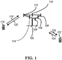
- FIG. 1 shows a multiple access wireless communication system according to one embodiment of the invention.
- An access network 100 includes multiple antenna groups, one including 104 and 106, another including 108 and 110, and an additional including 112 and 114. In FIG. 1 , only two antennas are shown for each antenna group, however, more or fewer antennas may be utilized for each antenna group.
- Access terminal 116 is in communication with antennas 112 and 114, where antennas 112 and 114 transmit information to access terminal 116 over forward link 120 and receive information from access terminal 116 over reverse link 118.
- Access terminal (AT) 122 is in communication with antennas 106 and 108, where antennas 106 and 108 transmit information to access terminal (AT) 122 over forward link 126 and receive information from access terminal (AT) 122 over reverse link 124.
- communication links 118, 120, 124 and 126 may use different frequency for communication.
- forward link 120 may use a different frequency then that used by reverse link 118.
- antenna groups each are designed to communicate to access terminals in a sector of the areas covered by access network 100.
- the transmitting antennas of access network 100 may utilize beamforming in order to improve the signal-to-noise ratio of forward links for the different access terminals 116 and 122. Also, an access network using beamforming to transmit to access terminals scattered randomly through its coverage causes less interference to access terminals in neighboring cells than an access network transmitting through a single antenna to all its access terminals.
- An access network may be a fixed station or base station used for communicating with the terminals and may also be referred to as an access point, a Node B, a base station, an enhanced base station, an evolved Node B (eNB), or some other terminology.
- An access terminal may also be called user equipment (UE), a wireless communication device, terminal, access terminal or some other terminology.
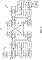
- FIG. 2 is a simplified block diagram of an embodiment of a transmitter system 210 (also known as the access network) and a receiver system 250 (also known as access terminal (AT) or user equipment (UE)) in a MIMO system 200.
- a transmitter system 210 also known as the access network
- a receiver system 250 also known as access terminal (AT) or user equipment (UE)
- traffic data for a number of data streams is provided from a data source 212 to a transmit (TX) data processor 214.
- TX transmit
- each data stream is transmitted over a respective transmit antenna.
- TX data processor 214 formats, codes, and interleaves the traffic data for each data stream based on a particular coding scheme selected for that data stream to provide coded data.
- the coded data for each data stream may be multiplexed with pilot data using OFDM techniques.
- the pilot data is typically a known data pattern that is processed in a known manner and may be used at the receiver system to estimate the channel response.
- the multiplexed pilot and coded data for each data stream is then modulated (i.e., symbol mapped) based on a particular modulation scheme (e.g., BPSK, QPSK, M-PSK, or M-QAM) selected for that data stream to provide modulation symbols.
- a particular modulation scheme e.g., BPSK, QPSK, M-PSK, or M-QAM
- the data rate, coding, and modulation for each data stream may be determined by instructions performed by processor 230.
- TX MIMO processor 220 may further process the modulation symbols (e.g., for OFDM).
- TX MIMO processor 220 then provides N T modulation symbol streams to N T transmitters (TMTR) 222a through 222t.
- TMTR TX MIMO processor 220 applies beamforming weights to the symbols of the data streams and to the antenna from which the symbol is being transmitted.
- Each transmitter 222 receives and processes a respective symbol stream to provide one or more analog signals, and further conditions (e.g., amplifies, filters, and upconverts) the analog signals to provide a modulated signal suitable for transmission over the MIMO channel.
- N T modulated signals from transmitters 222a through 222t are then transmitted from N T antennas 224a through 224t, respectively.
- the transmitted modulated signals are received by N R antennas 252a through 252r and the received signal from each antenna 252 is provided to a respective receiver (RCVR) 254a through 254r.
- Each receiver 254 conditions (e.g., filters, amplifies, and downconverts) a respective received signal, digitizes the conditioned signal to provide samples, and further processes the samples to provide a corresponding "received" symbol stream.
- An RX data processor 260 then receives and processes the N R received symbol streams from N R receivers 254 based on a particular receiver processing technique to provide N T "detected" symbol streams.
- the RX data processor 260 then demodulates, deinterleaves, and decodes each detected symbol stream to recover the traffic data for the data stream.
- the processing by RX data processor 260 is complementary to that performed by TX MIMO processor 220 and TX data processor 214 at transmitter system 210.
- a processor 270 periodically determines which pre-coding matrix to use (discussed below). Processor 270 formulates a reverse link message comprising a matrix index portion and a rank value portion.
- the reverse link message may comprise various types of information regarding the communication link and/or the received data stream.
- the reverse link message is then processed by a TX data processor 238, which also receives traffic data for a number of data streams from a data source 236, modulated by a modulator 280, conditioned by transmitters 254a through 254r, and transmitted back to transmitter system 210.
- the modulated signals from receiver system 250 are received by antennas 224, conditioned by receivers 222, demodulated by a demodulator 240, and processed by a RX data processor 242 to extract the reserve link message transmitted by the receiver system 250.
- Processor 230 determines which pre-coding matrix to use for determining the beamforming weights then processes the extracted message.
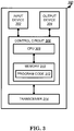
- FIG. 3 shows an alternative simplified functional block diagram of a communication device according to one embodiment of the invention.
- the communication device 300 in a wireless communication system can be utilized for realizing the UEs (or ATs) 116 and 122 in FIG. 1 , and the wireless communications system is preferably the LTE system.
- the communication device 300 may include an input device 302, an output device 304, a control circuit 306, a central processing unit (CPU) 308, a memory 310, a program code 312, and a transceiver 314.
- the control circuit 306 executes the program code 312 in the memory 310 through the CPU 308, thereby controlling an operation of the communications device 300.
- the communications device 300 can receive signals input by a user through the input device 302, such as a keyboard or keypad, and can output images and sounds through the output device 304, such as a monitor or speakers.
- the transceiver 314 is used to receive and transmit wireless signals, delivering received signals to the control circuit 306, and outputting signals generated by the control circuit 306 wirelessly.
- the communication device 300 in a wireless communication system can also be utilized for realizing the AN 100 in FIG. 1 .
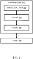
- FIG. 4 is a simplified block diagram of the program code 312 shown in FIG. 3 in accordance with one embodiment of the invention.
- the program code 312 includes an application layer 400, a Layer 3 portion 402, and a Layer 2 portion 404, and is coupled to a Layer 1 portion 406.
- the Layer 3 portion 402 generally performs radio resource control.
- the Layer 2 portion 404 generally performs link control.
- the Layer 1 portion 406 generally performs physical connections.
- 3GPP SP-110638 proposes a new study item on proximity-based services (ProSe), i.e., D2D (Device to Device) services.
- ProSe proximity-based services
- D2D Device to Device
- Proximity-based applications and services represent a recent and enormous socio-technological trend.
- the principle of these applications is to discover instances of the applications running in devices that are within proximity of each other, and ultimately also exchange application-related data.
- proximity-based discovery and communications in the public safety community.
- 3GPP technology has the opportunity to become the platform of choice to enable proximity-based discovery and communication between devices, and promote a vast array of future and more advanced proximity-based applications.
- the objective is to study use cases and identify potential requirements for an operator network controlled discovery and communications between devices that are in proximity, under continuous network control, and are under a 3GPP network coverage, for:
- RA Random Access
- 3GPP R2-141256 introduces a D2D resource request/grant procedure using random access (RA) procedure and a new MAC (Medium Access Control) control element, called D2D BSR (Buffer Status Report), as follows:
- This procedure applies only to communication mode 1.
- the UE has been configured with a logical channel for D2D Communication. It is also assumed that the UE is in RRC_CONNECTED. The purpose of this procedure is for the UE to get a grant from the eNB to transmit on the ProSe physical channel. There are two cases, whether the UE has a PUCCH resource to send the Scheduling Request on or not.
- the UE does not have a PUCCH resource
- Figure 1 shows how the random access procedure is used to support D2D Communication requests and grants.
- the D2D-BSR should be transmitted on the PUSCH similar to legacy BSR.
- the purpose of the D2D-BSR is for the UE to inform the eNB about the amount of data the UE has on logical channels related to D2D.
- the eNB configures the UE with a logical channel ID to be used for D2D communication. Although this makes it possible to reuse the existing BSR, it would require at least one logical channel group for D2D communication. If the UE is also configured with legacy LTE bearers and D2D discovery, the four existing logical channel groups may become a restriction.
- ProSe BSR MAC CE
- Proposal 3 Introduce a new MAC CE (ProSe BSR) which the UE uses to indicate the buffer status of D2D services.
- 3GPP R2-140625 proposes a mechanism, which is similar with legacy mechanism, for transmitting D2D BSR as follows:
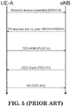
- Step 1.1 UE sends SR (Scheduling Request) to eNB via PUCCH; Step 1.2 eNB grants UL resource (for UE to send BSR) via PDCCH, scrambled by C-RNTI; Step 1.3 UE sends D2D BSR indicating the buffer status via PUSCH; Step 1.4 eNB grants D2D resource (for UE to send data) via PDCCH, scrambled by D2D-RNTI.
- SR Service Request
- Step 1.2 grants UL resource (for UE to send BSR) via PDCCH, scrambled by C-RNTI
- Step 1.3 UE sends D2D BSR indicating the buffer status via PUSCH;
- Step 1.4 eNB grants D2D resource (for UE to send data) via PDCCH, scrambled by D2D-RNTI.
- the UE Upon completion of this procedure the UE will have a D2D resource to transmit the data on.
- the UE Before performing a D2D transmission in coverage, the UE shall get a grant from the network.
- 3GPP TS 36.321 v11.2.0 introduces and describes how a BSR triggers a SR (Schedule Request)/D-SR (Dynamic Schedule Request) procedure or a Random Access procedure for transmission and legacy BSR format as follows:
- the random-access procedure shall be performed as follows:
- the UE shall monitor the PDCCH of the PCell for Random Access Response(s) identified by the RA-RNTI defined below, in the RA Response window which starts at the subframe that contains the end of the preamble transmission [7] plus three subframes and has length ra-ResponseWindowSize subframes.
- the UE may stop monitoring for Random Access Response(s) after successful reception of a Random Access Response containing Random Access Preamble identifiers that matches the transmitted Random Access Preamble.
- the eNB should not provide a grant smaller than 56 bits in the Random Access Response.
- Random Access Response reception is considered not successful and the UE shall:
- Contention Resolution is based on either C-RNTI on PDCCH of the PCell or UE Contention Resolution Identity on DL-SCH.
- the UE shall:
- the Scheduling Request (SR) is used for requesting UL-SCH resources for new transmission.
- the UE shall set the SR_COUNTER to 0.
- the UE shall for each TTI:
- the Buffer Status reporting procedure is used to provide the serving eNB with information about the amount of data available for transmission in the UL buffers of the UE.
- RRC controls BSR reporting by configuring the two timers periodicBSR-Timer and retxBSR-Timer and by, for each logical channel, optionally signalling logicalChannelGroup which allocates the logical channel to an LCG [8].
- the UE shall consider all radio bearers which are not suspended and may consider radio bearers which are suspended.
- a Buffer Status Report shall be triggered if any of the following events occur:
- a MAC PDU shall contain at most one MAC BSR control element, even when multiple events trigger a BSR by the time a BSR can be transmitted in which case the Regular BSR and the Periodic BSR shall have precedence over the padding BSR.
- the UE shall restart retxBSR-Timer upon indication of a grant for transmission of new data on any UL-SCH.
- All triggered BSRs shall be cancelled in case the UL grant(s) in this subframe can accommodate all pending data available for transmission but is not sufficient to additionally accommodate the BSR MAC control element plus its subheader. All triggered BSRs shall be cancelled when a BSR is included in a MAC PDU for transmission.
- the UE shall transmit at most one Regular/Periodic BSR in a TTI. If the UE is requested to transmit multiple MAC PDUs in a TTI, it may include a padding BSR in any of the MAC PDUs which do not contain a Regular/Periodic BSR.
- All BSRs transmitted in a TTI always reflect the buffer status after all MAC PDUs have been built for this TTI.
- Each LCG shall report at the most one buffer status value per TTI and this value shall be reported in all BSRs reporting buffer status for this LCG.
- a Padding BSR is not allowed to cancel a triggered Regular/Periodic BSR.
- a Padding BSR is triggered for a specific MAC PDU only and the trigger is cancelled when this MAC PDU has been built.
- a MAC PDU consists of a MAC header, zero or more MAC Service Data Units (MAC SDU), zero, or more MAC control elements, and optionally padding; as described in Figure 6 .1.2-3.
- MAC SDU MAC Service Data Units
- Both the MAC header and the MAC SDUs are of variable sizes.
- a MAC PDU header consists of one or more MAC PDU subheaders; each subheader corresponds to either a MAC SDU, a MAC control element or padding.
- a MAC PDU subheader consists of the six header fields R/R/E/LCID/F/L but for the last subheader in the MAC PDU and for fixed sized MAC control elements.
- the last subheader in the MAC PDU and subheaders for fixed sized MAC control elements consist solely of the four header fields R/R/E/LCID.
- a MAC PDU subheader corresponding to padding consists of the four header fields R/R/E/LCID.
- FIG. 6 [ Fig. 6 . 1 .2-1 of 3GPP TS 36.321 v11.2.0 has been reproduced as FIG. 6 .]
- FIG. 7 [ Fig. 6 . 1 .2-2 of 3GPP TS 36.321 v11.2.0 has been reproduced as FIG. 7 .]
- MAC PDU subheaders have the same order as the corresponding MAC SDUs, MAC control elements and padding.
- MAC control elements are always placed before any MAC SDU.
- Padding occurs at the end of the MAC PDU, except when single-byte or two-byte padding is required. Padding may have any value and the UE shall ignore it. When padding is performed at the end of the MAC PDU, zero or more padding bytes are allowed.
- one or two MAC PDU subheaders corresponding to padding are placed at the beginning of the MAC PDU before any other MAC PDU subheader.
- a maximum of one MAC PDU can be transmitted per TB per UE.
- a maximum of one MCH MAC PDU can be transmitted per TTI.
- FIG. 8 [ Fig. 6 . 1 .2-3 of 3GPP TS 36.321 v11.2.0 has been reproduced as FIG. 8 .]
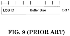
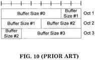
- BSR Buffer Status Report
- the BSR formats are identified by MAC PDU subheaders with LCIDs as specified in table 6.2.1-2.
- FIG. 9 [ Fig. 6 . 1 .3-1 of 3GPP TS 36.321 v11.2.0 has been reproduced as FIG. 9 .]
- FIG. 10 [ Fig. 6 . 1 .3-2 of 3GPP TS 36.321 v11.2.0 has been reproduced as FIG. 10 .]
- the MAC header and subheaders are octet aligned.
- Table 6.2.1-2 Values of LCID for UL-SCH Index LCID values 00000 CCCH 00001-01010 Identity of the logical channel 01011-11000 Reserved 11001 Extended Power Headroom Report 11010 Power Headroom Report 11011 C-RNTI 11100 Truncated BSR 11101 Short BSR 11110 Long BSR 11111 Padding
- 3GPP R1-143590 states:
- the only possible value of the number of transmissions of a given D2D communication MAC PDU is 4.
- Each transmission takes place in one subframe.
- the UE may need to consider (if possible) (i) how to use the transmission opportunities, or (ii) whether to send a Scheduling Assignment in the subsequent SA period and then be able to send the D2D data and/or the ProSe BSR through the resources associated with the subsequent SA period.
- the latency of transmitting the D2D data and transmission robustness between transmitter and receiver might need to be studied, especially for some services like urgent data or VoIP.
- the general concept of the invention is that UE needs to determine whether to send BSR and/or SR based on the available resources which have been allocated before the determination. More specifically, if D2D data arrives or ProSe BSR is triggered, UE would check if there are any available (whether sufficient or not) transmission opportunities / D2D grants in the current or the subsequent SA/Data Cycle, and would determine whether to trigger ProSe BSR or to cancel (or not send) the triggered ProSe BSR, or whether to send a scheduling request for D2D grant.
- the UE may not send the ProSe BSR to the base station if the data can be sent through D3 and/or D4, or even D5 ⁇ D7. If the D2D grant has been allocated previously by the base station and not yet used by the UE then UE may not trigger Scheduling Request for the new D2D data.
- Mode 1 means the UE needs to by itself select SA (randomly or following some specific rule) and derives the D2D resource associated with the SA.
- SA randomly or following some specific rule
- Mode 2 means the UE should send a request to base station, and the base station can then schedule D2D resource for the UE.
- the UE could skip D3/D4 of SA/Data Cycle 1 and could send a SA in the next SA period to send the data in the SA/Data Cycle 2.
- ProSe BSR or information of amount of D2D data could be sent by a first UE to the network or to a second UE (i.e., buffer status could be also sent between two different UEs except for between UE and network) since it might be also beneficial for the second UE to know how much data will be transmitted roughly in advance by the first UE.
- FIG. 13 is a flow chart 1300 in accordance with one first exemplary embodiment from the perspective of a UE.
- the UE sends a first scheduling assignment (SA) in a first SA period at a first timing.
- the UE considers a data available in the UE at a second timing, wherein the data needs to be transmitted and the second timing is later than the first timing.
- the UE skips a resource associated with the first SA for sending the data at a third timing, wherein the third timing is later than the second timing and earlier than a second SA period which is later than the first SA period.
- the first SA and the second SA are associated with a plurality of resources in a SA/Data Cycle.
- the plurality of resources could be associated with a T-RPT (Time Resource Pattern for Transmission).
- the UE sends a second SA in the second SA period.
- the UE transmits or sends the data on a resource associated with the second SA.
- the data could include control information (such as a BSR) and/or data information (such as upper layer data on the UE side).
- the UE determines whether to send a scheduling request or to trigger a BSR associated with the data based on the amount of existing or remaining resources associated with the SA which the UE could use.
- the UE does not trigger the BSR associated with the data.
- the UE triggers the BSR associated with the data.
- the UE does not send a base station (BS) the scheduling request (SR) associated with the triggered BSR.
- BS base station
- SR scheduling request
- the final UE behavior does not send a SR since the remaining resources are sufficient to carry all remaining buffered data. Since a triggered BSR could trigger SR, it is then foreseen not to send the triggered SR to request an UL grant for sending the triggered BSR.
- the device 300 includes a program code 312 stored in memory 310 of a UE.
- the CPU 308 could execute program code 312 to enable the UE to (i) send a first SA in a first SA period at a first timing, (ii) consider a data available in the UE at a second timing, wherein the data needs to be transmitted and the second timing is later than the first timing, (iii) skip a resource associated with the first SA for sending the data at a third timing, wherein the third timing is later than the second timing and earlier than a second SA period which is later than the first SA period, (iv) send a second SA in the second SA period, and (v) transmit or send the data on a resource associated with the second SA.
- the CPU could further execute program code 312 to enable the UE to determine whether to send a scheduling request or to trigger a BSR associated with the data based on the amount of existing or remaining resources associated with a SA which the UE could use.
- the UE does not trigger the BSR associated with the data.
- the UE triggers the BSR associated with the data.
- the UE does not send a base station the scheduling request (SR) associated with the triggered BSR.
- SR scheduling request
- the CPU 308 could execute the program code 312 to perform all of the above-described actions and steps or others described herein, in particular those described in paragraphs [0050] to [0054] above.
- FIG. 14 is a flow chart 1400 in accordance with one second exemplary embodiment from the perspective of a UE.
- the UE establishes a connection with a BS.
- the UE sends a first scheduling request to the BS.
- the UE receives a control signal from the BS.
- the UE sends a SA associated with the control signal at a first timing.
- the UE considers a data available in the UE at a second timing, wherein the data needs to be transmitted and the second timing is later than the first timing.
- the UE determines whether there is an available resource associated with the SA for transmitting the data.
- the SA is associated with a plurality of resources in a SA/Data Cycle.
- the plurality of resources could be associated with a T-RPT.
- the UE transmits or sends the data on the available resource at a third timing, wherein the third timing is later than the second timing.
- the data could include control information (such as a BSR) and/or data information (such as upper layer data in the UE side).
- the UE determines whether to send a second scheduling request or to trigger a BSR associated with the data based on the amount of remaining resources associated with the SA which the UE could use.
- the UE does not trigger the BSR associated with the data.
- the UE triggers the BSR associated with the data.
- the UE does not send the base station the second SR associated with the triggered BSR since the amount of remaining resources associated with the SA can accommodate the data to result in BSR cancellation.
- the final UE behavior does not send a SR since the remaining resources are sufficient to carry all remaining buffered data.
- a triggered BSR could trigger SR, it is foreseen not to send the triggered SR to request an UL grant for sending the triggered BSR.
- UE needs to send SR, which is triggered by the BSR, to request an UL grant and UE would use the UL grant for sending the BSR.
- SR which is triggered by the BSR
- the device 300 includes a program code 312 stored in memory 310 of a UE.
- the CPU 308 could execute program code 312 to enable the UE to (i) establish a connection with a BS, (ii) send a first scheduling request to the BS, (iii) receive a control signal from the BS, (iv) sending a SA associated with the control signal at a first timing, (v) consider a data available in the UE at a second timing, wherein the data needs to be transmitted and the second timing is later than the first timing, (vi) determine whether there is an available resource associated with the SA for transmitting the data, and (vii) transmit or send the data on the available resource at a third timing, wherein the third timing is later than the second timing.
- the CPU could further execute program code 312 to enable the UE to determine whether to send a second scheduling request or to trigger a BSR associated with the data based on the amount of existing or remaining resources associated with the SA which the UE could use.
- the UE does not trigger the BSR associated with the data.
- the UE triggers the BSR associated with the data.
- the UE does not send a base station the second scheduling request (SR) associated with the triggered BSR since the amount of remaining resources associated with the SA can accommodate the data to result in BSR cancellation.
- SR second scheduling request
- the CPU 308 could execute the program code 312 to perform all of the above-described actions and steps or others described herein, in particular those described in paragraphs [0057] to [0060] above.
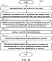
- FIG. 15 is a flow chart 1500 in accordance with one third exemplary embodiment from the perspective of a UE.
- the UE establishes a connection with a base station.
- the UE sends a first scheduling request to the BS.
- the UE receives a control signal from the BS.
- the UE sends a SA associated with the control signal in a SA period at a first timing.
- the SA is associated with a plurality of resources in a SA/Data Cycle.
- the plurality of resources could be associated with a T-RPT.
- the UE considers a data available in the UE at a second timing, wherein the data needs to be transmitted and the second timing is later than the first timing.
- the data could include control information (such as a BSR) and/or data information (such as upper layer data in the UE side).
- step 1530 the UE triggers a BSR associated with the data.
- step 1535 the UE cancels the BSR since the amount of remaining resources associated with the SA can accommodate the data.
- step 1540 the UE transmits the data on the remaining resources at a third timing, wherein the third timing is later than the second timing. In any case, the final UE behavior does not send a SR since the remaining resources are sufficient to carry all remaining buffered data. Since a triggered BSR could trigger SR, it is foreseen to cancel the just triggered BSR. Then it would not trigger any SR of course.
- steps 1530 and 1535 it is described that a BSR is triggered and then cancelled so actually UE would not send any SR for requesting an UL grant for sending any BSR (like doing nothing intentionally here).
- UE needs to send SR, which is triggered by the BSR, to request an UL grant and UE would use the UL grant for sending the BSR.
- SR which is triggered by the BSR
- the UE determines whether to send a second scheduling request or to trigger a BSR associated with the data based on the amount of existing or remaining resources associated with the SA which the UE could use. Alternatively or additionally preferably, the UE does not trigger the BSR associated with the data. As an alternative thereto, alternatively or additionally preferably, the UE triggers the BSR associated with the data. However, the UE does not send the base station the second SR associated with the triggered BSR since the amount of remaining resources associated with the SA can accommodate the data to result in BSR cancellation. In any case, the final UE behavior does not send a SR since the remaining resources are sufficient to carry all remaining buffered data.
- a triggered BSR could trigger SR, it is foreseen not to send the triggered SR to request an UL grant for sending the triggered BSR.
- UE needs to send SR, which is triggered by the BSR, to request an UL grant and UE would use the UL grant for sending the BSR.
- SR which is triggered by the BSR
- the device 300 includes a program code 312 stored in memory 310 of a UE.
- the CPU 308 could execute program code 312 to enable the UE to (i) establish a connection with a BS, (ii) send a first scheduling request to the BS, (iii) receive a control signal from the BS, (iv) sending a SA associated with the control signal in a SA period at a first timing, (v) consider a data available at a second timing, wherein the data needs to be transmitted and the second timing is later than the first timing, (vi) triggers a BSR associated with the data, (vii) cancel the BSR since the amount of remaining resources associated with the SA can accommodate the data, and (viii) transmit or send the data on the remaining resources at a third timing, wherein the third timing is later than the second timing.
- the CPU could further execute program code 312 to enable the UE to determine whether to send a second scheduling request or to trigger a BSR associated with the data based on the amount of existing or remaining resources associated with the SA which the UE could use.
- the UE does not trigger the BSR associated with the data.
- the UE triggers the BSR associated with the data.
- the UE does not send a base station the second scheduling request (SR) associated with the triggered BSR since the amount of remaining resources associated with the SA can accommodate the data to result in BSR cancellation.
- SR second scheduling request
- the CPU 308 could execute the program code 312 to perform all of the above-described actions and steps or others described herein, in particular those described in paragraphs [0064] to [0067] above.
- the control signal from the BS could be a D2D grant received on PDCCH in the physical layer.
- the D2D grant informs the UE which time and frequency resource the UE should send the SA (scheduling assignment) and D2D data in a specific SA/Data cycle.
- the control information could be a BSR (Buffer Status Report) Control Element in the MAC layer.
- concurrent channels may be established based on pulse repetition frequencies.
- concurrent channels may be established based on pulse position or offsets.
- concurrent channels may be established based on time hopping sequences.
- concurrent channels may be established based on pulse repetition frequencies, pulse positions or offsets, and time hopping sequences.
- the various illustrative logical blocks, modules, and circuits described in connection with the aspects disclosed herein may be implemented within or performed by an integrated circuit ("IC"), an access terminal, or an access point.
- the IC may comprise a general purpose processor, a digital signal processor (DSP), an application specific integrated circuit (ASIC), a field programmable gate array (FPGA) or other programmable logic device, discrete gate or transistor logic, discrete hardware components, electrical components, optical components, mechanical components, or any combination thereof designed to perform the functions described herein, and may execute codes or instructions that reside within the IC, outside of the IC, or both.
- a general purpose processor may be a microprocessor, but in the alternative, the processor may be any conventional processor, controller, microcontroller, or state machine.
- a processor may also be implemented as a combination of computing devices, e.g., a combination of a DSP and a microprocessor, a plurality of microprocessors, one or more microprocessors in conjunction with a DSP core, or any other such configuration.
- a software module e.g., including executable instructions and related data
- other data may reside in a data memory such as RAM memory, flash memory, ROM memory, EPROM memory, EEPROM memory, registers, a hard disk, a removable disk, a CD-ROM, or any other form of computer-readable storage medium known in the art.
- a sample storage medium may be coupled to a machine such as, for example, a computer/processor (which may be referred to herein, for convenience, as a "processor") such the processor can read information (e.g., code) from and write information to the storage medium.
- a sample storage medium may be integral to the processor.
- the processor and the storage medium may reside in an ASIC.
- the ASIC may reside in user equipment.
- the processor and the storage medium may reside as discrete components in user equipment.
- any suitable computer-program product may comprise a computer-readable medium comprising codes relating to one or more of the aspects of the disclosure.
- a computer program product may comprise packaging materials.
Landscapes
- Engineering & Computer Science (AREA)
- Computer Networks & Wireless Communication (AREA)
- Signal Processing (AREA)
- Quality & Reliability (AREA)
- Mobile Radio Communication Systems (AREA)
Applications Claiming Priority (1)
| Application Number | Priority Date | Filing Date | Title |
|---|---|---|---|
| US201462051500P | 2014-09-17 | 2014-09-17 |
Publications (2)
| Publication Number | Publication Date |
|---|---|
| EP2999286A1 EP2999286A1 (en) | 2016-03-23 |
| EP2999286B1 true EP2999286B1 (en) | 2020-04-15 |
Family
ID=54196788
Family Applications (1)
| Application Number | Title | Priority Date | Filing Date |
|---|---|---|---|
| EP15185676.2A Active EP2999286B1 (en) | 2014-09-17 | 2015-09-17 | Methods and apparatus for requesting resources in a wireless communication system |
Country Status (7)
| Country | Link |
|---|---|
| US (1) | US10568114B2 (ja) |
| EP (1) | EP2999286B1 (ja) |
| JP (1) | JP6649728B2 (ja) |
| KR (1) | KR101780375B1 (ja) |
| CN (1) | CN105451273B (ja) |
| ES (1) | ES2798312T3 (ja) |
| TW (1) | TWI612833B (ja) |
Families Citing this family (37)
| Publication number | Priority date | Publication date | Assignee | Title |
|---|---|---|---|---|
| KR102289116B1 (ko) * | 2014-08-08 | 2021-08-12 | 주식회사 아이티엘 | 단말간 통신을 지원하는 무선 통신 시스템에서 신호의 송수신 방법 및 장치 |
| CN106717052B (zh) * | 2014-09-25 | 2020-05-19 | Lg 电子株式会社 | 无线通信系统中取消触发的prose bsr的方法和装置 |
| US10165580B2 (en) * | 2014-10-30 | 2018-12-25 | Lg Electronics Inc. | Method for prohibiting from triggering scheduling request in a D2D communication system and device therefor |
| EP3216263A4 (en) * | 2014-11-06 | 2018-06-13 | LG Electronics Inc. | Method for canceling a sidelink buffer status report in a d2d communication system and device therefor |
| WO2016072590A1 (en) * | 2014-11-06 | 2016-05-12 | Lg Electronics Inc. | Method for canceling scheduling requests triggered by a sidelink buffer status report in a d2d communication system and device therefor |
| CN107006028A (zh) * | 2014-12-31 | 2017-08-01 | 富士通株式会社 | 缓存状态报告的生成方法、装置以及通信系统 |
| US10512105B2 (en) * | 2015-03-09 | 2019-12-17 | Lg Electronics Inc. | Method for operating a fast random access procedure in a wireless communication system and a device therefor |
| WO2016165124A1 (en) * | 2015-04-17 | 2016-10-20 | Panasonic Intellectual Property Corporation Of America | Multiple prose group communication during a sidelink control period |
| US20160323777A1 (en) * | 2015-04-28 | 2016-11-03 | Asustek Computer Inc. | Method and apparatus for supporting ue-to-network relay based on device to device service in a wireless communication system |
| EP3322248B1 (en) * | 2015-09-18 | 2023-08-02 | Huawei Technologies Co., Ltd. | Control information transmission method, transmitting end and receiving end |
| US10743336B2 (en) * | 2015-09-23 | 2020-08-11 | Telefonaktiebolaget Lm Ericsson (Publ) | Scheduling and transmitting control information and data for direct communication |
| EP3366074A4 (en) * | 2015-10-21 | 2019-05-01 | LG Electronics Inc. | METHOD FOR SELECTION OF PROSE DESTINATIONS OR SL ALLOCATIONS IN A D2D COMMUNICATION SYSTEM AND DEVICE THEREFOR |
| JP6726679B2 (ja) * | 2015-11-05 | 2020-07-22 | 富士通株式会社 | 通信装置および無線通信方法 |
| CN108293247B (zh) * | 2016-02-05 | 2020-12-25 | Oppo广东移动通信有限公司 | 通信方法、终端设备和网络设备 |
| BR112018068887A2 (pt) * | 2016-03-21 | 2019-01-22 | Ericsson Telefon Ab L M | equipamento de usuário, nó de rede e método desempenhado pelos mesmos na indicação de dados de enlace ascendente |
| CN108702771A (zh) * | 2016-03-31 | 2018-10-23 | 华为技术有限公司 | 一种缓存处理方法和用户设备 |
| EP3439410B1 (en) * | 2016-03-31 | 2021-10-13 | Ntt Docomo, Inc. | User equipment reporting buffer status |
| WO2017166311A1 (zh) * | 2016-04-01 | 2017-10-05 | 华为技术有限公司 | 一种上行信息的传输方法及设备、系统 |
| KR102554339B1 (ko) | 2016-04-15 | 2023-07-10 | 광동 오포 모바일 텔레커뮤니케이션즈 코포레이션 리미티드 | 무선 통신 방법 및 장치 |
| WO2018006313A1 (en) * | 2016-07-07 | 2018-01-11 | Panasonic Intellectual Property Corporation Of America | Improved semi-persistent resource allocation behavior for v2x transmissions |
| WO2018030710A1 (en) | 2016-08-11 | 2018-02-15 | Samsung Electronics Co., Ltd. | Method and apparatus for scheduling uplink data in mobile communication system |
| US11191073B2 (en) | 2016-08-12 | 2021-11-30 | Telefonaktiebolaget Lm Ericsson (Publ) | UL scheduling timing in TDD with 1 MS TTI and reduced processing time |
| WO2018084614A1 (en) * | 2016-11-02 | 2018-05-11 | Samsung Electronics Co., Ltd. | Resource selection method and corresponding equipment |
| CN110268758A (zh) * | 2016-11-30 | 2019-09-20 | 瑞典爱立信有限公司 | 操控具有不同定时对齐要求的用户的方法 |
| US11405939B2 (en) * | 2017-01-05 | 2022-08-02 | Motorola Mobility Llc | Scheduling request indication |
| US11291036B2 (en) | 2017-03-24 | 2022-03-29 | Qualcomm Incorporated | Scheduling requests and buffer status reports for low latency wireless communications |
| JP6637541B2 (ja) | 2017-04-26 | 2020-01-29 | 華碩電腦股▲ふん▼有限公司 | 無線通信システムにおいて、制御要素送信のためにリソースを要求するための方法及び装置 |
| CN108809582B (zh) | 2017-05-05 | 2021-07-20 | 华为技术有限公司 | 一种数据传输的方法和装置 |
| SG11202002512SA (en) * | 2017-09-21 | 2020-04-29 | Guangdong Oppo Mobile Telecommunications Corp Ltd | Buffer status reporting method, terminal, and computer storage medium |
| US10645610B2 (en) * | 2017-11-24 | 2020-05-05 | Mediatek Singapore Pte. Ltd. | Method and apparatus for skipping uplink transmission in mobile communications |
| CN111344959B (zh) * | 2017-12-27 | 2024-04-30 | 联想(新加坡)私人有限公司 | 波束恢复过程 |
| PL3751892T3 (pl) * | 2018-02-09 | 2023-09-25 | Beijing Xiaomi Mobile Software Co., Ltd. | Sposób powstrzymywania wyzwalacza i urządzenie do powstrzymywania wyzwalacza |
| CN110461021B (zh) * | 2018-02-13 | 2020-07-14 | 华为技术有限公司 | 一种调度请求取消方法及设备 |
| WO2020113433A1 (zh) * | 2018-12-04 | 2020-06-11 | Oppo广东移动通信有限公司 | 一种处理调度请求的方法及装置、终端 |
| US11350453B2 (en) | 2019-07-18 | 2022-05-31 | Samsung Electronics Co., Ltd. | System and method for performing transmission cancellation indication monitoring |
| CN112099832B (zh) * | 2020-11-04 | 2021-04-20 | 中国人民解放军国防科技大学 | 星载设备的单粒子翻转恢复方法及系统 |
| RU2762254C1 (ru) * | 2021-05-31 | 2021-12-17 | Бейджин Сяоми Мобайл Софтвеа Ко., Лтд. | Способ сохранения возможности запуска и аппарат для сохранения возможности запуска |
Family Cites Families (22)
| Publication number | Priority date | Publication date | Assignee | Title |
|---|---|---|---|---|
| KR100932264B1 (ko) | 2007-10-04 | 2009-12-16 | 한국전자통신연구원 | 피드백 메시지 기반의 상향 트래픽 전송 스케줄링 방법 및장치 |
| RU2672859C2 (ru) * | 2007-10-29 | 2018-11-20 | Анвайрд Плэнет, ЭлЭлСи | Способ и устройство в телекоммуникационной системе |
| US8559365B2 (en) * | 2007-10-30 | 2013-10-15 | Coppergate Communications Ltd. | After transmission return signal |
| KR101782759B1 (ko) * | 2008-02-01 | 2017-09-27 | 옵티스 와이어리스 테크놀로지, 엘엘씨 | 통신 단말기 및 우선순위가 매겨진 제어 정보를 사용하는 방법 |
| KR101494907B1 (ko) | 2008-02-01 | 2015-02-23 | 엘지전자 주식회사 | 기할당된 무선 자원을 이용한 효율적인 Buffer Status Report(BSR) 과정 수행 방법 |
| CN101778418B (zh) * | 2009-01-13 | 2014-03-19 | 中兴通讯股份有限公司 | 无线网络中触发或上报调度请求的方法和设备 |
| MA33263B1 (fr) * | 2009-05-05 | 2012-05-02 | Ericsson Telefon Ab L M | Traitement d'un déclencheur de demande de programmation |
| US8897252B2 (en) * | 2009-06-17 | 2014-11-25 | Htc Corporation | Method for transmitting data in a wireless communication system and system thereof |
| US9065545B2 (en) * | 2012-03-12 | 2015-06-23 | Blackberry Limited | Handling scheduling request collisions with an ACK/NACK repetition signal |
| EP2661138A1 (en) * | 2012-05-04 | 2013-11-06 | Panasonic Corporation | Threshold-based and power-efficient scheduling request procedure |
| US9526092B2 (en) * | 2012-05-14 | 2016-12-20 | Industrial Technology Research Institute | Method of allocating resources for scheduling request and user equipment using the same and a control node using the same |
| TWI620459B (zh) * | 2012-05-31 | 2018-04-01 | 內數位專利控股公司 | 在蜂巢式通訊系統中賦能直鏈通訊排程及控制方法 |
| US8913518B2 (en) * | 2012-08-03 | 2014-12-16 | Intel Corporation | Enhanced node B, user equipment and methods for discontinuous reception in inter-ENB carrier aggregation |
| US10123344B2 (en) | 2013-03-06 | 2018-11-06 | Qualcomm Incorporated | Methods and apparatus for multi-subframe scheduling |
| WO2015021185A1 (en) * | 2013-08-07 | 2015-02-12 | Interdigital Patent Holdings, Inc. | Distributed scheduling for device-to-device communication |
| CN105682137B (zh) * | 2013-08-09 | 2019-04-30 | 株式会社Kt | 终端之间直接通信中缓冲状态报告传输方法及其装置 |
| JP6169442B2 (ja) * | 2013-08-30 | 2017-07-26 | 京セラ株式会社 | 移動通信システム及びユーザ端末 |
| US10045249B2 (en) * | 2014-03-19 | 2018-08-07 | Lg Electronics Inc. | Method and apparatus for configuring buffer status report for public safety transmission or vehicle-related transmission in wireless communication system |
| KR101759609B1 (ko) * | 2014-03-20 | 2017-07-20 | 엘지전자 주식회사 | 무선 통신 시스템에서 신호를 송수신하기 위한 방법 및 이를 위한 장치 |
| US10462807B2 (en) * | 2014-05-09 | 2019-10-29 | Telefonaktiebolaget Lm Ericsson (Publ) | Methods, apparatus, and systems for determining communication priority |
| US9247546B2 (en) * | 2014-05-13 | 2016-01-26 | Lg Electronics Inc. | Allocation of resources for device-to-device (D2D) communication and method and apparatus for transmitting and receiving signal on the basis of the resource allocation |
| JP6601808B2 (ja) * | 2014-08-01 | 2019-11-06 | サン パテント トラスト | 通信装置、通信方法および集積回路 |
-
2015
- 2015-09-17 JP JP2015184528A patent/JP6649728B2/ja active Active
- 2015-09-17 ES ES15185676T patent/ES2798312T3/es active Active
- 2015-09-17 US US14/856,942 patent/US10568114B2/en active Active
- 2015-09-17 CN CN201510593881.7A patent/CN105451273B/zh active Active
- 2015-09-17 TW TW104130740A patent/TWI612833B/zh active
- 2015-09-17 KR KR1020150131666A patent/KR101780375B1/ko active IP Right Grant
- 2015-09-17 EP EP15185676.2A patent/EP2999286B1/en active Active
Non-Patent Citations (1)
| Title |
|---|
| None * |
Also Published As
| Publication number | Publication date |
|---|---|
| US20160081108A1 (en) | 2016-03-17 |
| CN105451273A (zh) | 2016-03-30 |
| KR101780375B1 (ko) | 2017-09-21 |
| CN105451273B (zh) | 2020-03-31 |
| JP6649728B2 (ja) | 2020-02-19 |
| TW201613399A (en) | 2016-04-01 |
| TWI612833B (zh) | 2018-01-21 |
| JP2016063545A (ja) | 2016-04-25 |
| EP2999286A1 (en) | 2016-03-23 |
| ES2798312T3 (es) | 2020-12-10 |
| KR20160033059A (ko) | 2016-03-25 |
| US10568114B2 (en) | 2020-02-18 |
Similar Documents
| Publication | Publication Date | Title |
|---|---|---|
| EP2999286B1 (en) | Methods and apparatus for requesting resources in a wireless communication system | |
| EP3007514B1 (en) | Method and apparatus for performing device to device (d2d) content estimation and triggering of buffer status reporting (bsr) in a wireless communication system | |
| CN109699088B (zh) | 无线通信系统中基于msg3的系统信息请求的方法和设备 | |
| US11317446B2 (en) | Method and apparatus of handling BWP inactivity timer during random access procedure in a wireless communication system | |
| US20210105126A1 (en) | Feedback for Wireless Communications | |
| US11595991B2 (en) | Method for indicating the allocated resources for a HARQ message in a random access procedure for a low-complexity, narrowband terminal | |
| EP3247054B1 (en) | Control information transmission method and apparatus in wireless communication system | |
| CN109526247B (zh) | 用于v2x传输的数据的改进的初始传输和重传 | |
| US10433343B2 (en) | Method and apparatus for improving random access procedure in a wireless communication system | |
| EP2975903B1 (en) | Method and apparatus for performing a random access (ra) procedure for device-to-device (d2d) service in a wireless communication system | |
| US11291012B2 (en) | Method and apparatus for selecting beam for preconfigured uplink resources in a wireless communication system | |
| WO2016175398A1 (ko) | 무선 통신 시스템에서 경쟁 기반 자원을 이용한 상향링크 데이터 송수신 방법 및 이를 위한 장치 | |
| EP2928253A1 (en) | Allocation of resources for concurrent device-to-device (d2d) communication sessions to a wireless device | |
| EP3387867B1 (en) | Terminal device, infrastructure equipment and methods for resource selection and updating of access class information | |
| EP4133648A2 (en) | Harq feedback of multicast and broadcast services | |
| KR20220154115A (ko) | 사이드링크 통신을 위한 리소스 예약 | |
| EP2963986A1 (en) | Method and apparatus for performing a random access (ra) procedure for a device-to-device (d2d) communication | |
| KR102598052B1 (ko) | 무선 이동 통신 시스템에서 물리 하향링크 제어 채널 명령에 기반해서 랜덤 액세스를 위한 상향 링크와 랜덤 액세스 설정을 선택하는 방법 및 장치 | |
| US20240163905A1 (en) | Channel Access Priority Class for Sidelink Feedback Transmission with Conflict Information |
Legal Events
| Date | Code | Title | Description |
|---|---|---|---|
| PUAI | Public reference made under article 153(3) epc to a published international application that has entered the european phase |
Free format text: ORIGINAL CODE: 0009012 |
|
| AK | Designated contracting states |
Kind code of ref document: A1 Designated state(s): AL AT BE BG CH CY CZ DE DK EE ES FI FR GB GR HR HU IE IS IT LI LT LU LV MC MK MT NL NO PL PT RO RS SE SI SK SM TR |
|
| AX | Request for extension of the european patent |
Extension state: BA ME |
|
| 17P | Request for examination filed |
Effective date: 20160923 |
|
| RBV | Designated contracting states (corrected) |
Designated state(s): AL AT BE BG CH CY CZ DE DK EE ES FI FR GB GR HR HU IE IS IT LI LT LU LV MC MK MT NL NO PL PT RO RS SE SI SK SM TR |
|
| STAA | Information on the status of an ep patent application or granted ep patent |
Free format text: STATUS: EXAMINATION IS IN PROGRESS |
|
| 17Q | First examination report despatched |
Effective date: 20170526 |
|
| GRAP | Despatch of communication of intention to grant a patent |
Free format text: ORIGINAL CODE: EPIDOSNIGR1 |
|
| STAA | Information on the status of an ep patent application or granted ep patent |
Free format text: STATUS: GRANT OF PATENT IS INTENDED |
|
| INTG | Intention to grant announced |
Effective date: 20191122 |
|
| GRAS | Grant fee paid |
Free format text: ORIGINAL CODE: EPIDOSNIGR3 |
|
| GRAA | (expected) grant |
Free format text: ORIGINAL CODE: 0009210 |
|
| STAA | Information on the status of an ep patent application or granted ep patent |
Free format text: STATUS: THE PATENT HAS BEEN GRANTED |
|
| AK | Designated contracting states |
Kind code of ref document: B1 Designated state(s): AL AT BE BG CH CY CZ DE DK EE ES FI FR GB GR HR HU IE IS IT LI LT LU LV MC MK MT NL NO PL PT RO RS SE SI SK SM TR |
|
| REG | Reference to a national code |
Ref country code: CH Ref legal event code: EP |
|
| REG | Reference to a national code |
Ref country code: DE Ref legal event code: R096 Ref document number: 602015050628 Country of ref document: DE |
|
| REG | Reference to a national code |
Ref country code: IE Ref legal event code: FG4D |
|
| REG | Reference to a national code |
Ref country code: AT Ref legal event code: REF Ref document number: 1258779 Country of ref document: AT Kind code of ref document: T Effective date: 20200515 |
|
| REG | Reference to a national code |
Ref country code: NL Ref legal event code: MP Effective date: 20200415 |
|
| REG | Reference to a national code |
Ref country code: LT Ref legal event code: MG4D |
|
| PG25 | Lapsed in a contracting state [announced via postgrant information from national office to epo] |
Ref country code: NL Free format text: LAPSE BECAUSE OF FAILURE TO SUBMIT A TRANSLATION OF THE DESCRIPTION OR TO PAY THE FEE WITHIN THE PRESCRIBED TIME-LIMIT Effective date: 20200415 Ref country code: PT Free format text: LAPSE BECAUSE OF FAILURE TO SUBMIT A TRANSLATION OF THE DESCRIPTION OR TO PAY THE FEE WITHIN THE PRESCRIBED TIME-LIMIT Effective date: 20200817 Ref country code: FI Free format text: LAPSE BECAUSE OF FAILURE TO SUBMIT A TRANSLATION OF THE DESCRIPTION OR TO PAY THE FEE WITHIN THE PRESCRIBED TIME-LIMIT Effective date: 20200415 Ref country code: LT Free format text: LAPSE BECAUSE OF FAILURE TO SUBMIT A TRANSLATION OF THE DESCRIPTION OR TO PAY THE FEE WITHIN THE PRESCRIBED TIME-LIMIT Effective date: 20200415 Ref country code: IS Free format text: LAPSE BECAUSE OF FAILURE TO SUBMIT A TRANSLATION OF THE DESCRIPTION OR TO PAY THE FEE WITHIN THE PRESCRIBED TIME-LIMIT Effective date: 20200815 Ref country code: SE Free format text: LAPSE BECAUSE OF FAILURE TO SUBMIT A TRANSLATION OF THE DESCRIPTION OR TO PAY THE FEE WITHIN THE PRESCRIBED TIME-LIMIT Effective date: 20200415 Ref country code: GR Free format text: LAPSE BECAUSE OF FAILURE TO SUBMIT A TRANSLATION OF THE DESCRIPTION OR TO PAY THE FEE WITHIN THE PRESCRIBED TIME-LIMIT Effective date: 20200716 Ref country code: NO Free format text: LAPSE BECAUSE OF FAILURE TO SUBMIT A TRANSLATION OF THE DESCRIPTION OR TO PAY THE FEE WITHIN THE PRESCRIBED TIME-LIMIT Effective date: 20200715 |
|
| REG | Reference to a national code |
Ref country code: AT Ref legal event code: MK05 Ref document number: 1258779 Country of ref document: AT Kind code of ref document: T Effective date: 20200415 |
|
| PG25 | Lapsed in a contracting state [announced via postgrant information from national office to epo] |
Ref country code: BG Free format text: LAPSE BECAUSE OF FAILURE TO SUBMIT A TRANSLATION OF THE DESCRIPTION OR TO PAY THE FEE WITHIN THE PRESCRIBED TIME-LIMIT Effective date: 20200715 Ref country code: RS Free format text: LAPSE BECAUSE OF FAILURE TO SUBMIT A TRANSLATION OF THE DESCRIPTION OR TO PAY THE FEE WITHIN THE PRESCRIBED TIME-LIMIT Effective date: 20200415 Ref country code: HR Free format text: LAPSE BECAUSE OF FAILURE TO SUBMIT A TRANSLATION OF THE DESCRIPTION OR TO PAY THE FEE WITHIN THE PRESCRIBED TIME-LIMIT Effective date: 20200415 Ref country code: LV Free format text: LAPSE BECAUSE OF FAILURE TO SUBMIT A TRANSLATION OF THE DESCRIPTION OR TO PAY THE FEE WITHIN THE PRESCRIBED TIME-LIMIT Effective date: 20200415 |
|
| REG | Reference to a national code |
Ref country code: ES Ref legal event code: FG2A Ref document number: 2798312 Country of ref document: ES Kind code of ref document: T3 Effective date: 20201210 |
|
| PG25 | Lapsed in a contracting state [announced via postgrant information from national office to epo] |
Ref country code: AL Free format text: LAPSE BECAUSE OF FAILURE TO SUBMIT A TRANSLATION OF THE DESCRIPTION OR TO PAY THE FEE WITHIN THE PRESCRIBED TIME-LIMIT Effective date: 20200415 |
|
| REG | Reference to a national code |
Ref country code: DE Ref legal event code: R097 Ref document number: 602015050628 Country of ref document: DE |
|
| PG25 | Lapsed in a contracting state [announced via postgrant information from national office to epo] |
Ref country code: SM Free format text: LAPSE BECAUSE OF FAILURE TO SUBMIT A TRANSLATION OF THE DESCRIPTION OR TO PAY THE FEE WITHIN THE PRESCRIBED TIME-LIMIT Effective date: 20200415 Ref country code: CZ Free format text: LAPSE BECAUSE OF FAILURE TO SUBMIT A TRANSLATION OF THE DESCRIPTION OR TO PAY THE FEE WITHIN THE PRESCRIBED TIME-LIMIT Effective date: 20200415 Ref country code: EE Free format text: LAPSE BECAUSE OF FAILURE TO SUBMIT A TRANSLATION OF THE DESCRIPTION OR TO PAY THE FEE WITHIN THE PRESCRIBED TIME-LIMIT Effective date: 20200415 Ref country code: RO Free format text: LAPSE BECAUSE OF FAILURE TO SUBMIT A TRANSLATION OF THE DESCRIPTION OR TO PAY THE FEE WITHIN THE PRESCRIBED TIME-LIMIT Effective date: 20200415 Ref country code: AT Free format text: LAPSE BECAUSE OF FAILURE TO SUBMIT A TRANSLATION OF THE DESCRIPTION OR TO PAY THE FEE WITHIN THE PRESCRIBED TIME-LIMIT Effective date: 20200415 Ref country code: DK Free format text: LAPSE BECAUSE OF FAILURE TO SUBMIT A TRANSLATION OF THE DESCRIPTION OR TO PAY THE FEE WITHIN THE PRESCRIBED TIME-LIMIT Effective date: 20200415 |
|
| PLBE | No opposition filed within time limit |
Free format text: ORIGINAL CODE: 0009261 |
|
| STAA | Information on the status of an ep patent application or granted ep patent |
Free format text: STATUS: NO OPPOSITION FILED WITHIN TIME LIMIT |
|
| PG25 | Lapsed in a contracting state [announced via postgrant information from national office to epo] |
Ref country code: PL Free format text: LAPSE BECAUSE OF FAILURE TO SUBMIT A TRANSLATION OF THE DESCRIPTION OR TO PAY THE FEE WITHIN THE PRESCRIBED TIME-LIMIT Effective date: 20200415 Ref country code: SK Free format text: LAPSE BECAUSE OF FAILURE TO SUBMIT A TRANSLATION OF THE DESCRIPTION OR TO PAY THE FEE WITHIN THE PRESCRIBED TIME-LIMIT Effective date: 20200415 |
|
| 26N | No opposition filed |
Effective date: 20210118 |
|
| PG25 | Lapsed in a contracting state [announced via postgrant information from national office to epo] |
Ref country code: MC Free format text: LAPSE BECAUSE OF FAILURE TO SUBMIT A TRANSLATION OF THE DESCRIPTION OR TO PAY THE FEE WITHIN THE PRESCRIBED TIME-LIMIT Effective date: 20200415 |
|
| REG | Reference to a national code |
Ref country code: CH Ref legal event code: PL |
|
| PG25 | Lapsed in a contracting state [announced via postgrant information from national office to epo] |
Ref country code: SI Free format text: LAPSE BECAUSE OF FAILURE TO SUBMIT A TRANSLATION OF THE DESCRIPTION OR TO PAY THE FEE WITHIN THE PRESCRIBED TIME-LIMIT Effective date: 20200415 |
|
| REG | Reference to a national code |
Ref country code: BE Ref legal event code: MM Effective date: 20200930 |
|
| PG25 | Lapsed in a contracting state [announced via postgrant information from national office to epo] |
Ref country code: LU Free format text: LAPSE BECAUSE OF NON-PAYMENT OF DUE FEES Effective date: 20200917 |
|
| PG25 | Lapsed in a contracting state [announced via postgrant information from national office to epo] |
Ref country code: IE Free format text: LAPSE BECAUSE OF NON-PAYMENT OF DUE FEES Effective date: 20200917 Ref country code: LI Free format text: LAPSE BECAUSE OF NON-PAYMENT OF DUE FEES Effective date: 20200930 Ref country code: CH Free format text: LAPSE BECAUSE OF NON-PAYMENT OF DUE FEES Effective date: 20200930 Ref country code: BE Free format text: LAPSE BECAUSE OF NON-PAYMENT OF DUE FEES Effective date: 20200930 |
|
| PG25 | Lapsed in a contracting state [announced via postgrant information from national office to epo] |
Ref country code: TR Free format text: LAPSE BECAUSE OF FAILURE TO SUBMIT A TRANSLATION OF THE DESCRIPTION OR TO PAY THE FEE WITHIN THE PRESCRIBED TIME-LIMIT Effective date: 20200415 Ref country code: MT Free format text: LAPSE BECAUSE OF FAILURE TO SUBMIT A TRANSLATION OF THE DESCRIPTION OR TO PAY THE FEE WITHIN THE PRESCRIBED TIME-LIMIT Effective date: 20200415 Ref country code: CY Free format text: LAPSE BECAUSE OF FAILURE TO SUBMIT A TRANSLATION OF THE DESCRIPTION OR TO PAY THE FEE WITHIN THE PRESCRIBED TIME-LIMIT Effective date: 20200415 |
|
| PG25 | Lapsed in a contracting state [announced via postgrant information from national office to epo] |
Ref country code: MK Free format text: LAPSE BECAUSE OF FAILURE TO SUBMIT A TRANSLATION OF THE DESCRIPTION OR TO PAY THE FEE WITHIN THE PRESCRIBED TIME-LIMIT Effective date: 20200415 |
|
| P01 | Opt-out of the competence of the unified patent court (upc) registered |
Effective date: 20230509 |
|
| PGFP | Annual fee paid to national office [announced via postgrant information from national office to epo] |
Ref country code: IT Payment date: 20230919 Year of fee payment: 9 Ref country code: GB Payment date: 20230811 Year of fee payment: 9 |
|
| PGFP | Annual fee paid to national office [announced via postgrant information from national office to epo] |
Ref country code: FR Payment date: 20230811 Year of fee payment: 9 Ref country code: DE Payment date: 20230818 Year of fee payment: 9 |
|
| PGFP | Annual fee paid to national office [announced via postgrant information from national office to epo] |
Ref country code: ES Payment date: 20231017 Year of fee payment: 9 |