EP2998937B1 - Display apparatus for vehicles, in particular for commercial vehicles - Google Patents
Display apparatus for vehicles, in particular for commercial vehicles Download PDFInfo
- Publication number
- EP2998937B1 EP2998937B1 EP15185665.5A EP15185665A EP2998937B1 EP 2998937 B1 EP2998937 B1 EP 2998937B1 EP 15185665 A EP15185665 A EP 15185665A EP 2998937 B1 EP2998937 B1 EP 2998937B1
- Authority
- EP
- European Patent Office
- Prior art keywords
- vehicle
- obstacle
- display
- calculation unit
- display system
- Prior art date
- Legal status (The legal status is an assumption and is not a legal conclusion. Google has not performed a legal analysis and makes no representation as to the accuracy of the status listed.)
- Active
Links
- 235000004522 Pentaglottis sempervirens Nutrition 0.000 claims description 8
- 230000001419 dependent effect Effects 0.000 claims description 5
- 240000004050 Pentaglottis sempervirens Species 0.000 claims description 4
- 238000009877 rendering Methods 0.000 claims 3
- 238000001514 detection method Methods 0.000 description 9
- 230000006399 behavior Effects 0.000 description 4
- 238000000034 method Methods 0.000 description 4
- 239000003086 colorant Substances 0.000 description 2
- 230000006870 function Effects 0.000 description 2
- 238000002604 ultrasonography Methods 0.000 description 2
- 230000000007 visual effect Effects 0.000 description 2
- 241000542420 Sphyrna tudes Species 0.000 description 1
- 238000004040 coloring Methods 0.000 description 1
- 239000012530 fluid Substances 0.000 description 1
- 230000012447 hatching Effects 0.000 description 1
- 210000003128 head Anatomy 0.000 description 1
- 230000004886 head movement Effects 0.000 description 1
- 230000001795 light effect Effects 0.000 description 1
- 230000007935 neutral effect Effects 0.000 description 1
- 230000003287 optical effect Effects 0.000 description 1
Images


Classifications
-
- G—PHYSICS
- G06—COMPUTING; CALCULATING OR COUNTING
- G06V—IMAGE OR VIDEO RECOGNITION OR UNDERSTANDING
- G06V20/00—Scenes; Scene-specific elements
- G06V20/50—Context or environment of the image
- G06V20/56—Context or environment of the image exterior to a vehicle by using sensors mounted on the vehicle
- G06V20/58—Recognition of moving objects or obstacles, e.g. vehicles or pedestrians; Recognition of traffic objects, e.g. traffic signs, traffic lights or roads
-
- G—PHYSICS
- G06—COMPUTING; CALCULATING OR COUNTING
- G06T—IMAGE DATA PROCESSING OR GENERATION, IN GENERAL
- G06T11/00—2D [Two Dimensional] image generation
-
- B—PERFORMING OPERATIONS; TRANSPORTING
- B60—VEHICLES IN GENERAL
- B60R—VEHICLES, VEHICLE FITTINGS, OR VEHICLE PARTS, NOT OTHERWISE PROVIDED FOR
- B60R1/00—Optical viewing arrangements; Real-time viewing arrangements for drivers or passengers using optical image capturing systems, e.g. cameras or video systems specially adapted for use in or on vehicles
- B60R1/20—Real-time viewing arrangements for drivers or passengers using optical image capturing systems, e.g. cameras or video systems specially adapted for use in or on vehicles
- B60R1/22—Real-time viewing arrangements for drivers or passengers using optical image capturing systems, e.g. cameras or video systems specially adapted for use in or on vehicles for viewing an area outside the vehicle, e.g. the exterior of the vehicle
- B60R1/23—Real-time viewing arrangements for drivers or passengers using optical image capturing systems, e.g. cameras or video systems specially adapted for use in or on vehicles for viewing an area outside the vehicle, e.g. the exterior of the vehicle with a predetermined field of view
- B60R1/24—Real-time viewing arrangements for drivers or passengers using optical image capturing systems, e.g. cameras or video systems specially adapted for use in or on vehicles for viewing an area outside the vehicle, e.g. the exterior of the vehicle with a predetermined field of view in front of the vehicle
-
- G—PHYSICS
- G06—COMPUTING; CALCULATING OR COUNTING
- G06V—IMAGE OR VIDEO RECOGNITION OR UNDERSTANDING
- G06V20/00—Scenes; Scene-specific elements
- G06V20/50—Context or environment of the image
- G06V20/52—Surveillance or monitoring of activities, e.g. for recognising suspicious objects
-
- H—ELECTRICITY
- H04—ELECTRIC COMMUNICATION TECHNIQUE
- H04N—PICTORIAL COMMUNICATION, e.g. TELEVISION
- H04N23/00—Cameras or camera modules comprising electronic image sensors; Control thereof
- H04N23/50—Constructional details
- H04N23/54—Mounting of pick-up tubes, electronic image sensors, deviation or focusing coils
-
- H—ELECTRICITY
- H04—ELECTRIC COMMUNICATION TECHNIQUE
- H04N—PICTORIAL COMMUNICATION, e.g. TELEVISION
- H04N23/00—Cameras or camera modules comprising electronic image sensors; Control thereof
- H04N23/60—Control of cameras or camera modules
- H04N23/63—Control of cameras or camera modules by using electronic viewfinders
-
- B—PERFORMING OPERATIONS; TRANSPORTING
- B60—VEHICLES IN GENERAL
- B60R—VEHICLES, VEHICLE FITTINGS, OR VEHICLE PARTS, NOT OTHERWISE PROVIDED FOR
- B60R2300/00—Details of viewing arrangements using cameras and displays, specially adapted for use in a vehicle
- B60R2300/30—Details of viewing arrangements using cameras and displays, specially adapted for use in a vehicle characterised by the type of image processing
- B60R2300/304—Details of viewing arrangements using cameras and displays, specially adapted for use in a vehicle characterised by the type of image processing using merged images, e.g. merging camera image with stored images
- B60R2300/305—Details of viewing arrangements using cameras and displays, specially adapted for use in a vehicle characterised by the type of image processing using merged images, e.g. merging camera image with stored images merging camera image with lines or icons
Definitions
- the present invention relates to a display device for vehicles, in particular commercial vehicles.
- Usually vehicles are equipped with devices for indirect vision in the immediate vehicle environment, such as side mirrors.
- Commercial vehicles for example, as a device for indirect vision, a main mirror on each of the driver side and the passenger side provided with which the driver can see a flat and horizontal part of the lane of certain width, which extends from a specified distance behind the eyes of the driver to the Horizon stretches. A strip of lesser width is also visible by means of these mirrors for the driver, but already starts at a shorter distance behind the eyes of the driver.
- wide-angle mirrors are also provided on both sides of the commercial vehicle, with which in each case an area behind the eyes of the driver can be viewed in a certain extension in the longitudinal direction of the vehicle, which is wider than the area visible through the main mirror, but only a certain length extends along the vehicle.
- a vehicle-mounted display can display at least a stylized recording of the passenger car from a bird's eye view. Sensors can detect an immediate area around the passenger car. If there is an appropriate detection of an obstacle, corresponding symbols flash on the display.
- an image acquisition unit continuously acquires an image, which is supplied by the image acquisition unit (video) data, for example by means of a calculation unit and, optionally after further processing, to a display located in the cab reproducing the driver permanently and at any time the corresponding surrounding area of the vehicle and possibly additional information, such.
- video image acquisition unit
- a display located in the cab reproducing the driver permanently and at any time the corresponding surrounding area of the vehicle and possibly additional information, such.
- collision indications, distances and the like represents the area around the vehicle.
- DE 10 2010 042 026 A1 discloses a method and apparatus for generating an image of at least one object in an environment of a vehicle in which the object has areas that are not visible to a sensor / camera of the vehicle.
- US 2014/0036064 A1 discloses a vision system for a vehicle which is particularly suitable for reversing the vehicle.
- DE 10 2010 010912 A1 discloses a driver assistance device with optical representation of detected objects.
- the DE 10 2011 010 624 A1 a display device for legally prescribed fields of view of a commercial vehicle in a cab of the commercial vehicle, the at least a display unit adapted to display at least two of the legally prescribed fields of view permanently and in real time on the display unit in the cab.
- an image display apparatus and method which allows any differences between the relative position of an obstacle, as it appears in a bird's-eye view image and in its current relative position, to be checked on the same display.
- a bird's eye view image is created from various captured images, which can display the vehicle environment. Thereupon, the bird's-eye view image and a single image captured by a camera are simultaneously displayed when an obstacle in the vehicle environment has been detected.
- a real image captured by a camera is usually displayed in real time by a reproduction unit for the driver in order to provide the driver with insight into areas which are difficult to see.
- the real images captured by the camera are a detailed representation of the prevailing scene of the vehicle environment at the time of acquisition.
- the real images captured by the camera have a wealth of information that, however, may be only partially of interest to the driver of the vehicle.
- directional indications refer to a vehicle, in particular commercial vehicle, during normal forward travel.
- lateral direction thus means that direction which is along the vertical to a forward direction of travel vector of the motor vehicle and corresponds to the left-right direction.
- immediate vehicle environment describes an area that extends directly from the vehicle adjacent to a predetermined distance, for example about 5 m, and around the vehicle.
- remote vehicle environment describes an area adjacent to the "immediate vehicle environment” and extending outward from the immediate vehicle environment.
- the term “remote vehicle environment” describes an area around the vehicle that is, for example, more than 5 meters away from the vehicle, as described above.
- a "stylized representation” is to be understood as a representation of an object whose appearance, as occurs in nature or reality, is abstracted and represented only in its essential basic structures.
- a “symbolic representation” describes a representation of an object whose appearance, as occurs in nature or reality, is greatly modified and represented with a predetermined symbol shape.
- obstacles in the description of this invention refer to any objects that may be in the immediate or distant vehicle environment while traveling with a vehicle, particularly a commercial vehicle.
- objects are meant that are of interest to the driver, eg. B. those objects with which the vehicle can collide and cause an accident.
- obstacles are in particular mobile objects, such as other road users, vehicles, cyclists, motorcyclists, pedestrians, etc. to call, for the most part an increased risk from the vehicle and represent an increased risk to the vehicle.
- stationary objects such as street signs, street posts, street lamps, garbage cans, Litfubbklalen, parked vehicles or other non-moving objects to name, which may also be of interest to the driver in addition to the moving obstacles.
- this may be an advantage in a Auspark- or maneuvering, so that the driver does not accidentally overlooks one of the stationary objects and causes a collision with this.
- they are moving objects of primary interest to the driver.
- those stationary object obstacles may be obstacles in the sense of the present application which are of interest to the driver for the current driving behavior and driving maneuvers and be critical, for example a street lamp located at an intersection in the area of the lane during a turning operation.
- the invention is based on the idea of providing a display device for a vehicle, in particular a commercial vehicle, which has a detection device that can be attached to the vehicle, a calculation unit that is connected to the detection device and a display unit that is connected to the calculation unit.
- the detection device is configured to detect at least a part of the immediate vehicle environment and to generate corresponding signals to the detected part of the immediate vehicle environment.
- the calculation unit is configured to receive the signals generated by the detection device, to detect obstacles in the detected vehicle environment and to generate a playback image.
- the playback image contains the vehicle in stylized or symbolic representation and, if at least one obstacle has been determined, the at least one detected obstacle in stylized or symbolic representation.
- the at least one detected obstacle is arranged on the display image relative to the vehicle in such a way as it is in reality relative to the vehicle.
- the reproduction unit is designed to display the playback image generated by the calculation unit inside the vehicle by the driver.
- the display device provides the driver with a playback image that represents the vehicle and at least one detected obstacle, which is located in the immediate vicinity of the vehicle, each stylized or symbolic.
- the driver can be presented with the current vehicle environment in a stylized and simplified manner and the driver quickly, easily and reliably provided with the relevant information about any obstacles in the immediate vehicle environment.
- the driver is provided and displayed only the necessary and relevant information of the vehicle environment, which is why the driver can "inform at a glance" about the vehicle environment, without being distracted by additional, irrelevant and annoying for the driver and irritating information.
- additional, irrelevant and disturbing for the driver and irritating information (video) to name ads that z.
- the playback image has a neutral background, such as a monochrome background, on which the vehicle and the detected obstacles are stylized or symbolized, so that the driver can quickly and easily read the necessary information.
- the display device may be adapted to have at least two different symbols, each of which may be associated with different obstacles, in particular movable and non-movable obstacles, stored and capable of displaying at least one of the symbols at a particular time. Further, as described in more detail below, the display device may be adapted to select the icons to be displayed after the obstacle has been removed from the vehicle (i.e., relative position) and / or type of obstacle (ie, moving obstacle or stationary obstacle).
- the display device can continuously, i.e. continuously, change over time the representation of the obstacle on the display image. in real time, or clocked, i. at intervals, done.
- movement of the obstacle on the display image may be fluid or halting, i. gradually, be imaged.
- the playback image represents the vehicle and the detected obstacle in plan view.
- the playback image represents the vehicle and the detected obstacle in bird's eye view in the forward direction of the vehicle from back to front, although other known representation perspectives are possible. With the two perspectives mentioned, it is easier for the driver to quickly gain an overview of the immediate vehicle environment, since he can quickly and reliably orientate himself to the stylized or symbolic representations, in particular of his own vehicle.
- the type and / size of the detected obstacle can be determined and the stylized or symbolic representation of the detected obstacle can be modified depending on the specific type and / or size of the obstacle.
- the modified representation of the obstacle or the selected symbol for the obstacle of the driver on the playback picture Quickly identify what type of obstacle, such as pedestrians, cyclists, motorcyclists or another vehicle, it is.
- the size of the obstacle can be determined and stylized in the case of symbolic representation are taken into account. So z. For example, a small vehicle may be represented with a smaller icon than a large bus, and both the small vehicle and the large bus may be represented with the same symbol.
- At least a part of a remote vehicle environment can also be detected.
- the playback image may be modified such that the playback image includes at least one hint area indicative of the obstacle detected in the remote vehicle environment and the location of the detected obstacle relative to the vehicle.
- the playback image in the lower and / or upper area each have a picture strip as a hint area, the z. Flashing, discoloring or otherwise indicating if an obstacle has been detected in the remote vehicle environment.
- the display unit is adapted to project the display image onto the windshield of the vehicle or onto a screen mounted separately in the driver's compartment of the vehicle, which is transparent, semi-transparent or non-transparent, for example by means of a head-up display or an OLED ( Organic Light Emitting Diode) displays.
- a head-up display or an OLED ( Organic Light Emitting Diode) displays By projecting the playback image on the windshield an at least partially transparent image is generated that affects the direct view of the driver through the windscreen only limited.
- the driver can still safely control the vehicle while continuing to be informed of any obstacles in the immediate and distant vehicle surroundings by means of the playback picture.
- the display image is projected onto a lower portion of the windshield and centered in front of the driver, so that the driver can pivot back and forth with the direct view from the direct view of the playback image with only small eye and head movements. This also contributes to the fast, uncomplicated and reliable informing about the vehicle environment.
- the playback image can also be projected onto other surfaces located in the interior of the vehicle, for example on the A-pillar.
- the playback image may be output on a display arranged inside the vehicle, for example on the display of a currently unused navigation device.
- the playback image can be viewed on a separate display in the driver's cab of the vehicle display or screen for the driver.
- the detection device is adapted to detect the entire immediate vehicle environment, i. H. the area completely directly around the vehicle.
- the display device according to the invention is able to detect the entire immediate vehicle environment and evaluate with respect to obstacles. The driver can therefore be provided with a playback image informing him of all objects in the immediate vicinity of the vehicle.
- the detection device can detect the immediate and remote vehicle surroundings by means of radar sensors and / or ultrasound sensors and / or image recording units, such as cameras, which can be attached to the vehicle, in particular commercial vehicle.
- the radar sensors and / or ultrasonic sensors and / or image recording units can send signals corresponding to the calculation unit, which can then be evaluated with regard to obstacles.
- the radar sensors and / or ultrasound sensors and / or image recording units can directly detect an obstacle in the detected part of the vehicle environment and send a corresponding signal to the calculation unit.
- the determination of the type of obstacle can be based on the movement behavior of the detected obstacle.
- previously determined obstacle data can be stored in a memory of the calculation unit and taken into account when determining new obstacles. For example, a pedestrian can make abrupt changes in direction while another vehicle, such as a car, can make only certain changes of direction in a given time.
- the playback image can be modified such that a plurality of detected obstacles of the same kind, which are relative to the vehicle in a certain area, to an obstacle group summarized and can be provided with a visual reference, such as a bracket or a frame around the obstacle group. This leads to an additional simplification of the playback image and can inform the driver qualitatively about obstacles in the bracket and indicate accordingly.
- the playback image permanently has the stylized or symbolically represented vehicle.
- the reproduction unit is designed to display the reproduction image generated and received by the calculation unit permanently and in real time.
- the detection device is also preferably designed to detect permanently and in real time part of the immediate and / or remote vehicle environment.
- the calculation unit is then designed to process the received signals permanently and in real time. Permanent means here that, for example, the presentation of the playback image is not interrupted by other information (temporally), so that the driver at any time can look at the playback unit in the vehicle environment and pointed out relevant obstacles.
- condition which is to be described as “permanently” and to be encompassed by it may also optionally be based on the ignition state of the vehicle or, for example, on a state in which a driver may be in the vehicle, eg. B. depending on detecting a located in the vicinity of the vehicle or in the vehicle key device, be extended.
- the vehicle is centrally located on the playback image so that the immediate vehicle environment contained in the playback image is approximately equal on all sides and thus the driver is informed equivalently of the entire immediate vehicle environment.
- the stylized or symbolic representation of the vehicle can take place instead of in digital form in the playback image as a replica of the vehicle applied to a display.
- the vehicle may be glued as a molded part on the display, wherein behind the display, the playback image is displayed digitally, which represents only the detected obstacles.
- the movement speed and / or direction of movement of the determined obstacle can be determined and the stylized or symbolic representation of the detected obstacle can be modified depending on the determined movement speed and / or movement direction of the obstacle.
- the symbol shape of the obstacle on the display image may be distorted depending on the speed of movement of the obstacle, and thus may preferably indicate the approximate direction of movement and, depending on the magnitude of the distortion, the speed of movement of the obstacle.
- a stationary pedestrian can be represented as a circular point
- a moving pedestrian can be represented as an oval or elliptical point.
- the longitudinal axis of the oval or elliptical point can indicate the direction of movement of the obstacle.
- the calculation unit may generate an arrow in the playback image that indicates the direction of movement of the obstacle. The length of the arrow can be selected in proportion to the speed of the obstacle.
- the playback image can be subdivided into several zones which, for example, can be arranged substantially concentrically around the vehicle stylized or symbolically represented on the playback image.
- the plurality of zones preferably represent critical and less critical zones, with the critical zones closer to the vehicle and the less critical zones further away from the vehicle.
- the zones may, for example, be displayed in the form of lines on the playback picture or, alternatively, be invisible.
- the calculation unit may be further configured to determine in which zone the detected obstacle is located.
- the calculation unit may be configured to modify the stylized or symbolic representation of the obstacle on the playback image, for example in different colors or in different brightness (brightness levels) or by a certain other symbol or in different sizes.
- the display device may represent the obstacle (s) differently depending on its distance.
- the playback image can also be modified such that the playback image additionally lane lines having a trace of the vehicle limit. Should the driver unintentionally deviate from the lane, for example without setting a turn signal, the lane line to which the vehicle deviates from the optimum lane can be graphically highlighted. As a result, the calculation unit can further help to provide the driver with a kind of lane keeping assistance.
- the lane lines can be displayed permanently and / or immutable in the playback image.
- the permanently displayed lane lines which indicate the lane of the vehicle, support the driver and have the function to better and faster oriented on the playback picture.
- the trajectory of the obstacle located in the immediate vicinity of the vehicle can be recorded and displayed in the form of an obstacle lane, wherein the displayed obstacle lane, consisting of various previously displayed positions of the obstacle, becomes time-faded and transparent.
- the driver can be informed of the past trajectory of the obstacle, from which he may possibly estimate a future trajectory.
- the future trajectory of the obstacle can be estimated and displayed on the playback image by means of z. B. an arrow or a future obstacle track are displayed.
- the obstacle type can be determined by means of object recognition, with each movement type being assigned a movement behavior.
- the assigned movement behavior can be stored specific to obstacles in a memory or a database.
- the Fig. 1 schematically represents the immediate vehicle environment of a vehicle 10, in particular a commercial vehicle.
- the non-hatched areas 11-16 respectively represent areas that can be detected by a front mirror, a front side mirror and the main mirrors and the wide-angle mirrors.
- the stand in the Fig. 1 hatched areas 17 and 18, each representing areas that can not be detected by the facilities for indirect vision.
- Fig. 2 are schematically those viewing range of the vehicle 10 of the Fig. 1 shown that can be detected directly by the driver of the vehicle 10.
- the non-hatched areas 21-25 each represent areas that can be directly detected by drivers.
- the stands in the Fig. 2 hatched area 26, which represents the area that can not be detected directly by the driver of the vehicle 10.
- the area 26 therefore separates the areas 22 and 23 or the areas 23 and 26 from one another, since the A pillars of the vehicle 10 block the direct view here.
- main mirror and wide-angle mirror see Fig. 5 ), which partially obstruct the driver's direct vision, so that the area 26 separates the areas 21 and 22 and the areas 24 and 25, respectively.
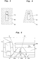
- FIG. 3 a reproduced image 20 produced by a display device according to the invention and viewable by the driver.
- the reproduction image 20 has a reproduction image 20 in FIG Fig. 3 shown stylized representation of the vehicle 10 and a detected by a detection device of the display device according to the invention immediate vehicle environment 30 on.
- the playback image 20 is in the Fig.
- the playback image 20 may have any other shape, such as round, oval, elliptical, triangular, trapezoidal.
- the vehicle 10 and the detected immediate vehicle environment 30 are shown in plan view.
- the playback image 20 is shown in trapezoidal shape and represents the vehicle 10 and the detected immediate vehicle environment 30 in bird's eye view in the forward direction of the vehicle 10 from the rear to the front. Due to the bird's-eye view of Fig. 4 For example, the vehicle 10 is partially distorted on the display image 20.
- the Fig. 5 schematically shows the driver's compartment of the vehicle 10 from the perspective of a driver. From the Fig. 5 shows, among other things, that the main mirror 2, the wide-angle mirror 4 and the A-pillar 6, the direct view into the vehicle environment partially obstruct (see Fig. 2 ). Furthermore, in the Fig. 5 shown different positions at which a display unit of the display device according to the invention can represent the playback image 20 - 20d.
- the position of the reproduction image 20 on the windshield 8 of the vehicle 10 is preferred, wherein the reproduction image 20 can be projected by the reproduction unit, for example a projector, head-up display or OLED display.
- the playback image 20 is preferably located at the lower portion of the windshield 8 and centered in front of the driver, so just above the steering wheel 9.
- Alternative positions for the playback image 20a - 20d are z.
- B a projection on the A-pillar 6, a representation in the instrument panel 7, a representation or projection next to the steering wheel 9 or in an upper, substantially central region
- a separate screen can be mounted in the vehicle interior, onto which the playback image 20 can be projected.
- the screen is preferably located between the driver and the windshield 8, for example on the dashboard.
- the screen can be angled relative to the front screen 8.
- commercial vehicles have Almost vertically extending windscreens, which is why an angled canvas can lead to a better projection and representation of the playback image 20.
- the canvas can be completely transparent, semitransparent or even not transparent.
- exemplary playback images 20 are shown at various times, each representing the vehicle and an obstacle 40 detected in the immediate vehicle environment 30, such as an automobile. As a pedestrian, have. That in the Fig. 6a to 6c illustrated obstacle 40 is symbolically contained in the form of a circular dot in the playback image 20.
- FIGS Fig. 6a - 6c the vehicle 10 standing at an intersection in front of a red traffic light.
- the obstacle 40 is still right behind the vehicle 10, for example, on a pavement, not shown in the playback image.
- the obstacle 40 has moved to right next to the vehicle 10.
- the driver can not detect the obstacle via the direct view and even with difficulty through the side mirrors.
- the obstacle 40 has moved further forward and is now right in front of the vehicle 10. Even at this time, the driver 40 can detect the obstacle 40 on the direct view or the mirror of the vehicle 10 only difficult.
- the driver can be provided continuously or at timed intervals a playback image that him to the in the Fig. 6a - 6b informed about the immediate vehicle environment and he can quickly and reliably detect the obstacle 40.
- FIG. 12 shows an exemplary playback image 20 that includes the vehicle 10, detected obstacles 40, 42, and 44, such as pedestrians, and a detected obstacle 46, such as a vehicle. Furthermore, goes from the Fig. 7 that the immediate vehicle environment 30 contained in the playback image 20 is divided into three zones, namely a near-vehicle zone 52, a middle zone 54 and a more remote zone 56.
- the zones 52, 54, 56 are each delimited by dashed lines, the dashed lines can be displayed in the playback image 20 or alternatively can be invisible on the playback image 20. Zones 52, 54, and 56 are critical, less critical, and sometimes noncritical regions depending on the distance from the vehicle 10.
- zones 52, 54, 56 may be dependent on other parameters, such as driver visibility of the vehicle , To be defined, so that directly visible areas classified as uncritical and not directly visible areas, such. As the range of the blind spot, can be classified as a critical area.
- a calculation unit of the display device detects an obstacle 40 located in the zone 52
- the calculation unit can modify the playback image such that the critical obstacle 40 is highlighted, for example in red and / or flashing and / or otherwise changed.
- the obstacles 42 and 44 located in different zones 54, 56 are also shown differently, for example, with different colors or brightness or luminance.
- the obstacle 46 which is partially in the zone 54 and partially in the zone 56, can be represented as a function of the larger portion in which it is located in one of the two zones 54, 56.
- the representation of the obstacle 46 corresponds to the representation of an obstacle in the zone 54, i. the zone in which the main part of the obstacle 46 lies.
- the playback image 20 comprises the vehicle 10 in a stylized representation and a plurality of obstacles 40 - 45, which are relative to the vehicle in a common area of the vehicle environment 30.
- the computing unit may combine obstacles 40-45 located in a common area in the vehicle environment to form an obstacle group 48 and mark it by means of an indicator 50, for example a bracket ,
- the obstacles 40 - 45 as in the Fig. 8 shown to be of the same obstacle type.
- different types of obstacles located in a common area in the vehicle environment may be grouped together to form an obstacle group.
- the hint 50 may be configured to frame the obstacle group 48 only partially so that the individual obstacles 40-45 are still clearly visible.
- the indication 50 can be configured such that the individual obstacles 40-45 are completely covered by the reference 50 and accordingly the obstacles 40-45 can no longer be recognized individually.
- the indicia 50 covers the obstacles 40-45, but is at least partially transparent, so that the obstacles 40 - 45 are still partially visible individually.
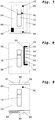
- FIG. 9 another example playback image 20 is shown. That in the Fig. 9 Playback image 20 shown has the vehicle 10 and a detected in the immediate vehicle environment 30 obstacle 40 in stylized or symbolic representation.
- the playback image 20 has the Fig. 9 an upper reference area 60 subdivided into two sections 61, 62, and a lower reference area 64 divided into two sections 65, 66, wherein in other embodiments the reference areas 60 and 64 may each have only one section or more than two sections.
- the calculation unit may modify that indication area corresponding to the approximate position of the obstacle determined in the remote vehicle area relative to the vehicle such that the driver receives an indication of the obstacle located in the remote vehicle environment.
- the computing unit modifies the representation of the left portion 65 of the lower hint area 64, for example, by hatching, coloring, or otherwise indicating that the driver is aware that an obstacle may be moving from the remote vehicle environment into the immediate vehicle environment 30 ,
- FIG. 10 - 12 Further exemplary playback images 20 are shown.
- the in the Fig. 10 - 12 Playback images 20 shown each have the vehicle 10 and the lane 70 of the vehicle 10 limiting lane lines 72, 74.
- Lane lines 72, 74 may, for example, correspond to the lane lines actually on the roadway.
- the lane lines 72, 74 are stationary relative to the vehicle and shown in identical shape.
- the calculation unit may modify the reproduction image 20 such that the lane line (in FIG Fig. 11 the lane line 72) is highlighted. As a result, the driver can be signaled that an unwanted lane deviation exists.
- the lane generator may generate the lane lines 72, 74 on the display image 20 during the lane change such that the lane lines correspond to the actual position of the lane lines 72, 74 relative to the vehicle (see FIG Fig. 12 ).
Description
Die vorliegende Erfindung betrifft eine Anzeigeeinrichtung für Fahrzeuge, insbesondere Nutzfahrzeuge.The present invention relates to a display device for vehicles, in particular commercial vehicles.
Üblicherweise sind Fahrzeuge mit Einrichtungen zur indirekten Sicht in die unmittelbare Fahrzeugumgebung, wie beispielsweise Seitenspiegel, ausgestattet. An Nutzfahrzeugen ist beispielsweise als Einrichtung zur indirekten Sicht ein Hauptspiegel auf jeweils der Fahrerseite und der Beifahrerseite vorgesehen, mit welchem der Fahrzeugführer einen ebenen und horizontalen Teil der Fahrbahn von bestimmter Breite einsehen kann, der sich ab einer festgelegten Entfernung hinter den Augenpunkten des Fahrzeugführers bis zum Horizont erstreckt. Ein Streifen geringerer Breite ist ebenfalls mittels dieser Spiegel für den Fahrzeugführer einsehbar, der jedoch bereits in kürzerer Entfernung hinter den Augenpunkten des Fahrers beginnt.Usually vehicles are equipped with devices for indirect vision in the immediate vehicle environment, such as side mirrors. Commercial vehicles, for example, as a device for indirect vision, a main mirror on each of the driver side and the passenger side provided with which the driver can see a flat and horizontal part of the lane of certain width, which extends from a specified distance behind the eyes of the driver to the Horizon stretches. A strip of lesser width is also visible by means of these mirrors for the driver, but already starts at a shorter distance behind the eyes of the driver.
Neben diesen Hauptspiegeln sind beidseitig des Nutzfahrzeugs ferner Weitwinkelspiegel vorgesehen, mit denen jeweils ein Bereich hinter den Augenpunkten des Fahrers in einer bestimmten Erstreckung in Längsrichtung des Fahrzeugs eingesehen werden kann, welcher breiter als der durch den Hauptspiegel einsehbare Bereich ist, sich jedoch nur eine bestimmte Länge entlang des Fahrzeugs erstreckt.In addition to these primary mirrors, wide-angle mirrors are also provided on both sides of the commercial vehicle, with which in each case an area behind the eyes of the driver can be viewed in a certain extension in the longitudinal direction of the vehicle, which is wider than the area visible through the main mirror, but only a certain length extends along the vehicle.
Darüber hinaus sind Einparkhilfen für Personenkraftwagen bekannt, bei denen ein im Fahrzeuginneren angeordnetes Display zumindest eine stilisierte Aufnahme des Personenraftwagens aus der Vogelperspektive anzeigen kann. Sensoren können einen unmittelbaren Bereich um den Personenkraftwagen herum erfassen. Wenn eine entsprechende Erfassung eines Hindernisses vorliegt, blinken entsprechende Symbole auf dem Display auf.In addition, parking aids for passenger cars are known in which a vehicle-mounted display can display at least a stylized recording of the passenger car from a bird's eye view. Sensors can detect an immediate area around the passenger car. If there is an appropriate detection of an obstacle, corresponding symbols flash on the display.
In letzter Zeit ist es zunehmend angedacht, neben herkömmlichen Spiegeln als Einrichtungen zur indirekten Sicht entweder in Ergänzung oder als Ersatz für die Spiegel Kamerasysteme bzw. Bildaufnahmesysteme als Einrichtungen zur indirekten Sicht einzusetzen. Bei solchen Bildaufnahmesystemen erfasst eine Bildaufnahmeeinheit kontinuierlich ein Bild, wobei diese von der Bildaufnahmeeinheit erfassten (Video-)Daten, beispielsweise mittels einer Berechnungseinheit und, gegebenenfalls nach Weiterbearbeitung, an eine im Fahrerhaus befindliche Wiedergabeeinrichtung geliefert werden, welche für den Fahrer dauerhaft und jederzeit einsehbar den entsprechenden Umgebungsbereich des Fahrzeugs und ggf. ergänzende Information, wie z. B. Kollisionshinweise, Abstände und Ähnliches, für den Bereich rund um das Fahrzeug darstellt.Recently, it is increasingly being considered, in addition to conventional mirrors as devices for indirect vision either in addition or as a replacement for the mirror camera systems or image recording systems as devices for indirect vision. In such image recording systems, an image acquisition unit continuously acquires an image, which is supplied by the image acquisition unit (video) data, for example by means of a calculation unit and, optionally after further processing, to a display located in the cab reproducing the driver permanently and at any time the corresponding surrounding area of the vehicle and possibly additional information, such. As collision indications, distances and the like, represents the area around the vehicle.
Trotz dieser vorgeschriebenen Spiegel bzw. Einrichtungen für indirekte Sicht ist es jedoch für einen Fahrzeugführer kaum möglich bzw. sehr schwierig, die unfallkritischen Bereiche rund um ein Nutzfahrzeug jederzeit vollständig und ausreichend im Auge zu behalten. Zudem ist aufgrund der Vielzahl der Spiegel die Anforderung an den Fahrzeugführer erhöht, diese Spiegel nahezu gleichzeitig im Auge zu behalten.Despite these prescribed mirrors or devices for indirect vision, however, it is hardly possible or very difficult for a driver to keep track of the accident-critical areas around a commercial vehicle at all times and sufficiently. In addition, due to the large number of mirrors, the requirement for the driver to keep track of these mirrors almost simultaneously.
Gerade bei Nutzfahrzeugen wie LKWs, Bussen etc. ist die Einsehbarkeit auf den Fahrerseiten kritisch. Hindernisse und andere Verkehrsteilnehmer werden schlecht erkannt, da die Bereiche der toten Winkel verhältnismäßig groß sind und somit Hindernisse, wie beispielsweise andere Verkehrsteilnehmer, in der Einrichtung zur indirekten Sicht nicht erkennbar sind. Auch ist die Orientierung für den Fahrer auf den verhältnismäßig zahlreichen Einrichtungen für indirekte Sicht schwierig, so dass die Gefahr besteht, dass gerade bei Abbiege- oder Rangiervorgängen Hindernisse übersehen werden, obwohl sie in der Einrichtung für indirekte Sicht abgebildet sind. So werden häufig Unfälle aufgrund dessen verursacht, dass der Fahrer des Nutzfahrzeugs nicht ausreichenden Einblick in seitliche Bereiche des Fahrzeugs besitzt, insbesondere in die toten Winkel, die einen seitlichen Bereich neben dem Fahrzeug darstellen, der durch den Fahrer trotz der oben beschriebenen Außenspiegel kaum bzw. nicht einsehbar ist.Especially with commercial vehicles such as trucks, buses, etc., the visibility on the driver's side is critical. Obstacles and other road users are poorly recognized because the areas of the blind spots are relatively large and thus obstacles, such as other road users, are not recognizable in the device for indirect vision. Also, the orientation for the driver on the relatively numerous devices for indirect vision is difficult, so that there is a risk that especially in turning or maneuvering obstacles are overlooked, although they are displayed in the device for indirect vision. Thus, accidents are often caused due to the fact that the driver of the utility vehicle does not have sufficient insight into lateral areas of the vehicle, in particular in the blind spots, which represent a lateral area next to the vehicle, by the driver despite the above-described mirrors hardly or is not visible.
Daher ist es bekannt, Hindernisse auf einem Wiedergabebild durch graphische Einblendung, wie beispielsweise farbige Rahmen oder dergleichen, hervorzuheben. Auch akustische bzw. visuelle Warnsignale mittels Lautsprechern bzw. Lichteffekten zum Hinweisen auf Hindernisse, die sich in der unmittelbaren Fahrzeugumgebung befinden, sind bekannt. Nachteilig hierbei ist, dass durch die graphischen Einblendungen Teile des Wiedergabebilds verdeckt werden und dadurch häufig die genaue Lokalisierung des Hindernisses auf dem Wiedergabebild nicht eindeutig ist bzw. die Orientierung für den Fahrer auf dem Wiedergabebild erschwert ist.Therefore, it is known to highlight obstacles on a display image by graphic fade, such as colored frames or the like. Also, acoustic or visual warning signals by means of loudspeakers or light effects for indicating obstacles which are located in the immediate vehicle environment are known. The disadvantage here is that parts of the playback image are obscured by the graphic overlays and thus often the exact location of the obstacle on the playback image is not clear or the orientation for the driver on the playback image is difficult.
Ferner offenbart die
In der
Aus der
Weitere Fahrerassistenzsysteme sind aus der
Bei den bekannten Systemen und Verfahren wird jeweils zumeist ein mit einer Kamera erfasstes reales Bild in Echtzeit von einer Wiedergabeeinheit für den Fahrer einsehbar dargestellt, um dem Fahrer einen Einblick in schwer einsehbare Bereiche zu verschaffen. Die von der Kamera erfassten realen Bilder sind eine detailgetreue Abbildung der zum Zeitpunkt der Erfassung vorherrschenden Szenerie der Fahrzeugumgebung. Somit weisen die von der Kamera erfassten realen Bilder eine Fülle von Informationen auf, die jedoch nur teilweise für den Fahrer des Fahrzeugs von Interesse sein können.In the case of the known systems and methods, a real image captured by a camera is usually displayed in real time by a reproduction unit for the driver in order to provide the driver with insight into areas which are difficult to see. The real images captured by the camera are a detailed representation of the prevailing scene of the vehicle environment at the time of acquisition. Thus, the real images captured by the camera have a wealth of information that, however, may be only partially of interest to the driver of the vehicle.
Davon ausgehend ist es Aufgabe der Erfindung eine Anzeigeeinrichtung für ein Fahrzeug, insbesondere Nutzfahrzeug, bereitzustellen, das den Fahrer zuverlässig und vereinfacht über sich in der Fahrzeugumgebung befindliche Hindernisse informiert.On this basis, it is the object of the invention to provide a display device for a vehicle, in particular a commercial vehicle, which informs the driver reliably and simply about obstacles in the vehicle environment.
Diese Aufgabe wird mit einer Anzeigeeinrichtung für Fahrzeuge, insbesondere Nutzfahrzeuge, mit den Merkmalen des Anspruchs 1 gelöst. Bevorzugte Ausführungsformen sind in den abhängigen Ansprüchen angegeben.This object is achieved with a display device for vehicles, in particular commercial vehicles, with the features of claim 1. Preferred embodiments are given in the dependent claims.
In der Beschreibung dieser Erfindung beziehen sich Richtungsangaben auf ein Fahrzeug, insbesondere Nutzfahrzeug, bei normaler Vorwärtsfahrt. In seitlicher Richtung bedeutet somit diejenige Richtung, die entlang der Senkrechten zu einem Vorwärtsfahrtrichtungsvektor des Kraftfahrzeugs ist und der Links-Rechts-Richtung entspricht. Ferner beschreibt der Begriff "unmittelbare Fahrzeugumgebung" einen Bereich, der sich direkt vom Fahrzeug angrenzend zu einem vorbestimmten Abstand, beispielsweise ungefähr 5 m, und um das Fahrzeug herum erstreckt. Im Gegensatz dazu beschreibt der Begriff "entfernte Fahrzeugumgebung" einen Bereich, der an die "unmittelbare Fahrzeugumgebung" angrenzt und sich von der unmittelbaren Fahrzeugumgebung nach außen erstreckt. Beispielsweise beschreibt der Begriff "entfernte Fahrzeugumgebung" einen Bereich um das Fahrzeug herum, der beispielsweise mehr als die oben beschriebenen 5 m vom Fahrzeug beabstandet ist. Ferner ist unter einer "stilisierten Darstellung" eine Darstellung eines Objekts zu verstehen, dessen Erscheinungsbild, wie es in der Natur bzw. Wirklichkeit vorkommt, abstrahiert und nur in seinen wesentlichen Grundstrukturen dargestellt wird. Außerdem beschreibt eine "symbolische Darstellung" eine Darstellung eines Objekts, dessen Erscheinungsbild, wie es in der Natur bzw. Wirklichkeit vorkommt, stark abgewandelt und mit einer vorbestimmten Symbolform dargestellt wird.In the description of this invention, directional indications refer to a vehicle, in particular commercial vehicle, during normal forward travel. In the lateral direction thus means that direction which is along the vertical to a forward direction of travel vector of the motor vehicle and corresponds to the left-right direction. Further, the term "immediate vehicle environment" describes an area that extends directly from the vehicle adjacent to a predetermined distance, for example about 5 m, and around the vehicle. In contrast, the term "remote vehicle environment" describes an area adjacent to the "immediate vehicle environment" and extending outward from the immediate vehicle environment. For example, the term "remote vehicle environment" describes an area around the vehicle that is, for example, more than 5 meters away from the vehicle, as described above. Furthermore, a "stylized representation" is to be understood as a representation of an object whose appearance, as occurs in nature or reality, is abstracted and represented only in its essential basic structures. In addition, a "symbolic representation" describes a representation of an object whose appearance, as occurs in nature or reality, is greatly modified and represented with a predetermined symbol shape.
Ferner beziehen sich Hindernisse in der Beschreibung dieser Erfindung auf jegliche Objekte, die sich während einer Fahrt mit einem Fahrzeug, insbesondere Nutzfahrzeug, in der unmittelbaren oder entfernten Fahrzeugumgebung befinden können. Als Hindernisse sind beispielsweise Objekte gemeint, die für den Fahrer von Interesse sind, z. B. diejenigen Objekte, mit denen das Fahrzeug kollidieren und einen Unfall verursachen kann. Als beispielhafte Hindernisse sind insbesondere bewegliche Objekte, wie beispielsweise andere Verkehrsteilnehmer, Fahrzeuge, Fahrradfahrer, Motorradfahrer, Fußgänger, etc. zu nennen, für die zumeist eine erhöhte Gefahr von dem Fahrzeug ausgeht und die eine erhöhte Gefahr für das Fahrzeug darstellen.Further, obstacles in the description of this invention refer to any objects that may be in the immediate or distant vehicle environment while traveling with a vehicle, particularly a commercial vehicle. As obstacles, for example, objects are meant that are of interest to the driver, eg. B. those objects with which the vehicle can collide and cause an accident. As example obstacles are in particular mobile objects, such as other road users, vehicles, cyclists, motorcyclists, pedestrians, etc. to call, for the most part an increased risk from the vehicle and represent an increased risk to the vehicle.
Es sind aber auch neben den beweglichen Hindernissen auch stationäre Objekte, wie beispielsweise Straßenschilder, Straßenpfosten, Straßenlaternen, Mülltonnen, Litfaßsäulen, parkende Fahrzeuge oder sonstige nicht bewegliche Objekte zu nennen, die unter Umständen für den Fahrer auch von Interesse sein können. Beispielsweise kann dies bei einem Auspark- oder Rangiervorgang von Vorteil sein, damit der Fahrer nicht versehentlich eines der stationären Objekte übersieht und mit diesem eine Kollision verursacht. Bevorzugt sind es jedoch die beweglichen Objekte, die für den Fahrer primär von Interesse sind. Es können jedoch zusätzlich diejenigen stationären Objekt Hindernisse im Sinne der vorliegenden Anmeldung sein, die für das aktuelle Fahrverhalten und Fahrmanöver für den Fahrer von Interesse sind und kritisch sein, beispielsweise eine an einer Kreuzung befindliche Straßenlaterne im Bereich der Fahrspur bei einem Abbiegevorgang.But there are also stationary objects, such as street signs, street posts, street lamps, garbage cans, Litfaßsäulen, parked vehicles or other non-moving objects to name, which may also be of interest to the driver in addition to the moving obstacles. For example, this may be an advantage in a Auspark- or maneuvering, so that the driver does not accidentally overlooks one of the stationary objects and causes a collision with this. Preferably, however, they are moving objects of primary interest to the driver. However, in addition, those stationary object obstacles may be obstacles in the sense of the present application which are of interest to the driver for the current driving behavior and driving maneuvers and be critical, for example a street lamp located at an intersection in the area of the lane during a turning operation.
Der Erfindung liegt der Gedanke zugrunde, eine Anzeigeeinrichtung für ein Fahrzeug, insbesondere Nutzfahrzeug, bereitzustellen, die eine am Fahrzeug anbringbare Erfassungsvorrichtung, eine mit der Erfassungsvorrichtung in Verbindung stehende Berechnungseinheit und eine mit der Berechnungseinheit in Verbindung stehende Wiedergabeeinheit aufweist. Die Erfassungsvorrichtung ist dazu ausgebildet, zumindest einen Teil der unmittelbaren Fahrzeugumgebung zu erfassen und dem erfassten Teil der unmittelbaren Fahrzeugumgebung entsprechende Signale zu erzeugen. Die Berechnungseinheit ist dazu ausgebildet, die von der Erfassungsvorrichtung erzeugten Signale zu empfangen, Hindernisse in der erfassten Fahrzeugumgebung zu ermitteln und ein Wiedergabebild zu erzeugen. Das Wiedergabebild enthält das Fahrzeug in stilisierter oder symbolischer Darstellung und, sofern zumindest ein Hindernis ermittelt worden ist, das zumindest eine ermittelte Hindernis in stilisierter oder symbolischer Darstellung. Das zumindest eine ermittelte Hindernis befindet sich dabei auf dem Wiedergabebild relativ zum Fahrzeug derart angeordnet, wie es sich in Wirklichkeit relativ zum Fahrzeug befindet. Die Wiedergabeeinheit ist dazu ausgebildet, das von der Berechnungseinheit erzeugte Wiedergabebild im Inneren des Fahrzeugs durch den Fahrer einsehbar darzustellen.The invention is based on the idea of providing a display device for a vehicle, in particular a commercial vehicle, which has a detection device that can be attached to the vehicle, a calculation unit that is connected to the detection device and a display unit that is connected to the calculation unit. The detection device is configured to detect at least a part of the immediate vehicle environment and to generate corresponding signals to the detected part of the immediate vehicle environment. The calculation unit is configured to receive the signals generated by the detection device, to detect obstacles in the detected vehicle environment and to generate a playback image. The playback image contains the vehicle in stylized or symbolic representation and, if at least one obstacle has been determined, the at least one detected obstacle in stylized or symbolic representation. The at least one detected obstacle is arranged on the display image relative to the vehicle in such a way as it is in reality relative to the vehicle. The reproduction unit is designed to display the playback image generated by the calculation unit inside the vehicle by the driver.
Durch die erfindungsgemäße Anzeigeeinrichtung wird dem Fahrer ein Wiedergabebild bereitgestellt, das das Fahrzeug und zumindest ein ermitteltes Hindernis, das sich in unmittelbarer Fahrzeugumgebung befindet, jeweils stilisiert oder symbolisch darstellt. Dadurch kann dem Fahrer die aktuelle Fahrzeugumgebung stilisiert und vereinfacht dargestellt und dem Fahrer schnell, unkompliziert und zuverlässig die relevanten Informationen über etwaigen Hindernisse in der unmittelbaren Fahrzeugumgebung verschafft werden. Somit werden dem Fahrer nur die für ihn nötigen und relevanten Informationen der Fahrzeugumgebung bereitgestellt und angezeigt, weshalb sich der Fahrer "auf einen Blick" über die Fahrzeugumgebung informieren kann, ohne durch zusätzliche, irrelevante und für den Fahrer störende und irritierende Informationen abgelenkt zu werden. Beispielsweise sind als zusätzliche, irrelevante und für den Fahrer störende und irritierende Informationen (Video)Anzeigen zu nennen, die z. B. unkritische Objekte wie Bäume, Gebäude, Hintergründe und unkritische Objekte aufweisen. Vorzugsweise hat das Wiedergabebild einen neutralen Hintergrund, beispielsweise einen einfarbigen Hintergrund, auf dem das Fahrzeug und die ermittelten Hindernisse stilisiert oder symbolisch dargestellt werden, damit der Fahrer schnell und einfach die nötigen Informationen ablesen kann.The display device according to the invention provides the driver with a playback image that represents the vehicle and at least one detected obstacle, which is located in the immediate vicinity of the vehicle, each stylized or symbolic. In this way, the driver can be presented with the current vehicle environment in a stylized and simplified manner and the driver quickly, easily and reliably provided with the relevant information about any obstacles in the immediate vehicle environment. Thus, the driver is provided and displayed only the necessary and relevant information of the vehicle environment, which is why the driver can "inform at a glance" about the vehicle environment, without being distracted by additional, irrelevant and annoying for the driver and irritating information. For example, as additional, irrelevant and disturbing for the driver and irritating information (video) to name ads that z. B. uncritical Objects such as trees, buildings, backgrounds and uncritical objects exhibit. Preferably, the playback image has a neutral background, such as a monochrome background, on which the vehicle and the detected obstacles are stylized or symbolized, so that the driver can quickly and easily read the necessary information.
Die Anzeigevorrichtung kann derart angepasst sein, dass sie zumindest zwei verschiedene Symbole, die jeweils unterschiedlichen Hindernissen zugeordnet sein können, insbesondere beweglichen und nicht beweglichen Hindernissen, gespeichert vorliegen hat und zumindest eines der Symbole zu einem jeweiligen Zeitpunkt anzeigen kann. Des Weiteren, wie nachfolgend noch detaillierter beschrieben, kann die Anzeigevorrichtung derart angepasst sein, dass die Auswahl der anzuzeigenden Symbole nach Entfernung des Hindernisses zum Fahrzeug (d.h. Relativposition) und/oder Art des Hindernisses (insbesondere bewegliches Hindernis oder stationäres Hindernis) getroffen wird.The display device may be adapted to have at least two different symbols, each of which may be associated with different obstacles, in particular movable and non-movable obstacles, stored and capable of displaying at least one of the symbols at a particular time. Further, as described in more detail below, the display device may be adapted to select the icons to be displayed after the obstacle has been removed from the vehicle (i.e., relative position) and / or type of obstacle (ie, moving obstacle or stationary obstacle).
Ferner kann die erfindungsgemäße Anzeigeeinrichtung die zeitliche Änderung der Darstellung des Hindernisses auf dem Wiedergabebild kontinuierlich, d.h. in Echtzeit, oder getaktet, d.h. in zeitlichen Abständen, erfolgen. So kann ein die Bewegung des Hindernisses auf dem Wiedergabebild fließend oder stockend, d.h. schrittweise, abgebildet werden.Furthermore, the display device according to the invention can continuously, i.e. continuously, change over time the representation of the obstacle on the display image. in real time, or clocked, i. at intervals, done. Thus, movement of the obstacle on the display image may be fluid or halting, i. gradually, be imaged.
Vorzugsweise stellt das Wiedergabebild das Fahrzeug und das ermittelte Hindernis in Draufsicht dar. In einer weiteren Ausgestaltung stellt das Wiedergabebild das Fahrzeug und das ermittelte Hindernis in Vogelperspektive in Vorwärtsrichtung des Fahrzeugs von hinten nach vorne dar, wobei auch andere bekannte Darstellungsperspektiven möglich sind. Mit den beiden genannten Perspektiven ist es für den Fahrer vereinfacht, sich schnell einen Überblick über die unmittelbare Fahrzeugumgebung zu verschaffen, da er sich an den stilisierten oder symbolischen Darstellungen, insbesondere des eigenen Fahrzeugs, schnell und zuverlässig orientieren kann.Preferably, the playback image represents the vehicle and the detected obstacle in plan view. In another embodiment, the playback image represents the vehicle and the detected obstacle in bird's eye view in the forward direction of the vehicle from back to front, although other known representation perspectives are possible. With the two perspectives mentioned, it is easier for the driver to quickly gain an overview of the immediate vehicle environment, since he can quickly and reliably orientate himself to the stylized or symbolic representations, in particular of his own vehicle.
In einer weiteren Ausgestaltung der erfindungsgemäßen Anzeigeeinrichtung kann die Art und/Größe des ermittelten Hindernisses bestimmt werden und die stilisierte oder symbolische Darstellung des ermittelten Hindernisses in Abhängigkeit der bestimmten Art und/oder Größe des Hindernisses modifiziert werden. Anhand der modifizierten Darstellung des Hindernisses bzw. des gewählten Symbols für das Hindernis kann der Fahrer auf dem Wiedergabebild schnell erkennen, um welche Hindernisart, beispielsweise Fußgänger, Fahrradfahrer, Motorradfahrer oder ein weiteres Fahrzeug, es sich handelt. Hierbei kann z. B. jeder Hindernisart ein unterschiedliches Symbol, wie beispielsweise Kreis, Rechteck, Quadrat, Dreieck oder sonstige Formen, zugeordnet werden, das auf die entsprechende Hindernisart hinweist. Zusätzlich oder alternativ kann die Größe des Hindernisses ermittelt und bei der stilisierten oder symbolischen Darstellung berücksichtigt werden. So kann z. B. ein kleines Fahrzeug mit einem kleineren Symbol dargestellt werden als ein großer Bus, wobei sowohl das kleine Fahrzeug als auch der große Bus mit dem gleichen Symbol dargestellt sein können.In a further embodiment of the display device according to the invention, the type and / size of the detected obstacle can be determined and the stylized or symbolic representation of the detected obstacle can be modified depending on the specific type and / or size of the obstacle. Based on the modified representation of the obstacle or the selected symbol for the obstacle of the driver on the playback picture Quickly identify what type of obstacle, such as pedestrians, cyclists, motorcyclists or another vehicle, it is. This z. B. each Obstisart a different symbol, such as circle, rectangle, square, triangle or other forms, are assigned, which indicates the appropriate obstacle type. Additionally or alternatively, the size of the obstacle can be determined and stylized in the case of symbolic representation are taken into account. So z. For example, a small vehicle may be represented with a smaller icon than a large bus, and both the small vehicle and the large bus may be represented with the same symbol.
In einer weiteren Ausgestaltung der erfindungsgemäßen Anzeigeeinrichtung kann ferner zumindest ein Teil einer entfernten Fahrzeugumgebung erfasst werden. Das Wiedergabebild kann derart modifiziert werden, dass das Wiedergabebild zumindest einen Hinweisbereich enthält, der auf das in der entfernten Fahrzeugumgebung ermittelte Hindernis und die Position des ermittelten Hindernisses relativ zum Fahrzeug hinweist. Beispielsweise kann das Wiedergabebild im unteren und/oder oberen Bereich jeweils einen Bildstreifen als Hinweisbereich aufweisen, der z. B. aufblinkt, sich verfärbt oder anderweitig einen Hinweis gibt, wenn ein Hindernis in der entfernten Fahrzeugumgebung erfasst wurde.In a further embodiment of the display device according to the invention, at least a part of a remote vehicle environment can also be detected. The playback image may be modified such that the playback image includes at least one hint area indicative of the obstacle detected in the remote vehicle environment and the location of the detected obstacle relative to the vehicle. For example, the playback image in the lower and / or upper area each have a picture strip as a hint area, the z. Flashing, discoloring or otherwise indicating if an obstacle has been detected in the remote vehicle environment.
Vorzugsweise ist die Wiedergabeeinheit dazu ausgebildet, das Wiedergabebild auf die Frontscheibe des Fahrzeugs oder auf eine separat in der Fahrerzelle des Fahrzeugs angebrachte Leinwand, die transparent, semi-transparent oder nicht transparent ist, zu projizieren, beispielsweise mittels eines Head Up Displays oder eines OLED(Organic Light Emitting Diode)-Displays. Durch die Projektion des Wiedergabebildes auf die Frontscheibe wird ein zumindest teilweise transparentes Bild erzeugt, dass die direkte Sicht des Fahrers durch die Frontscheibe nur beschränkt beeinträchtigt. Somit kann der Fahrer aufgrund der direkten Sicht das Fahrzeug weiterhin sicher steuern, während er weiterhin mittels dem Wiedergabebild über etwaige Hindernisse in der unmittelbaren und entfernten Fahrzeugumgebung informiert wird. Vorzugsweise wird das Wiedergabebild auf einen unteren Bereich der Frontscheibe und mittig vor den Fahrer projiziert, so dass der Fahrer mit nur kleinen Augen- und Kopfbewegungen von der direkten Sicht auf das Wiedergabebild hin und wieder zurück auf die direkte Sicht schwenken kann. Dies trägt ebenfalls dem schnellen, unkomplizierten und zuverlässigen Informieren über die Fahrzeugumgebung bei.Preferably, the display unit is adapted to project the display image onto the windshield of the vehicle or onto a screen mounted separately in the driver's compartment of the vehicle, which is transparent, semi-transparent or non-transparent, for example by means of a head-up display or an OLED ( Organic Light Emitting Diode) displays. By projecting the playback image on the windshield an at least partially transparent image is generated that affects the direct view of the driver through the windscreen only limited. Thus, due to the direct view, the driver can still safely control the vehicle while continuing to be informed of any obstacles in the immediate and distant vehicle surroundings by means of the playback picture. Preferably, the display image is projected onto a lower portion of the windshield and centered in front of the driver, so that the driver can pivot back and forth with the direct view from the direct view of the playback image with only small eye and head movements. This also contributes to the fast, uncomplicated and reliable informing about the vehicle environment.
In einer weiteren Ausgestaltung der erfindungsgemäßen Anzeigeeinrichtung kann das Wiedergabebild auch auf andere sich im Inneren des Fahrzeugs befindlichen Flächen, wie beispielsweise auf die A-Säule, projiziert werden. Alternativ kann das Wiedergabebild auf einem im Inneren des Fahrzeugs angeordneten Display ausgegeben werden, beispielsweise auf dem Display eines momentan nicht verwendeten Navigationsgeräts. In einer weiteren Ausgestaltung kann das Wiedergabebild auf einem separat in der Fahrerzelle des Fahrzeugs angeordneten Display oder Bildschirm für den Fahrer einsehbar dargestellt sein.In a further embodiment of the display device according to the invention, the playback image can also be projected onto other surfaces located in the interior of the vehicle, for example on the A-pillar. Alternatively, the playback image may be output on a display arranged inside the vehicle, for example on the display of a currently unused navigation device. In a further embodiment For example, the playback image can be viewed on a separate display in the driver's cab of the vehicle display or screen for the driver.
Vorzugsweise ist die Erfassungsvorrichtung dazu ausgebildet, die gesamte unmittelbare Fahrzeugumgebung zu erfassen, d. h. den sich vollständig unmittelbar um das Fahrzeug erstreckenden Bereich. Somit ist die erfindungsgemäße Anzeigeeinrichtung in der Lage, die gesamte unmittelbare Fahrzeugumgebung zu erfassen und hinsichtlich Hindernisse auszuwerten. Dem Fahrer kann deshalb ein Wiedergabebild bereitgestellt werden, das ihn über alle sich in der unmittelbaren Fahrzeugumgebung befindlichen Objekte informiert.Preferably, the detection device is adapted to detect the entire immediate vehicle environment, i. H. the area completely directly around the vehicle. Thus, the display device according to the invention is able to detect the entire immediate vehicle environment and evaluate with respect to obstacles. The driver can therefore be provided with a playback image informing him of all objects in the immediate vicinity of the vehicle.
In einer weiteren Ausgestaltung der erfindungsgemäßen Anzeigeeinrichtung kann die Erfassungsvorrichtung die unmittelbare und entfernte Fahrzeugumgebung mittels Radarsensoren und/oder Ultraschallsensoren und/oder Bildaufnahmeeinheiten, wie beispielsweise Kameras, erfassen, die am Fahrzeug, insbesondere Nutzfahrzeug, anbringbar sind. Die Radarsensoren und/oder Ultraschallsensoren und/oder Bildaufnahmeeinheiten können an die Berechnungseinheit entsprechende Signale senden, die daraufhin hinsichtlich Hindernisse ausgewertet werden können. Alternativ oder zusätzlich können die Radarsensoren und/oder Ultraschallsensoren und/oder Bildaufnahmeeinheiten direkt ein Hindernis im erfassten Teil der Fahrzeugumgebung ermitteln und ein entsprechendes Signal an die Berechnungseinheit senden. Ferner kann es vorteilhaft sein, aus der zeitlichen Änderung des Orts des Hindernisses auf dem Wiedergabebild die Bewegungsgeschwindigkeit und/oder Bewegungsrichtung des Hindernisses festzustellen.In a further embodiment of the display device according to the invention, the detection device can detect the immediate and remote vehicle surroundings by means of radar sensors and / or ultrasound sensors and / or image recording units, such as cameras, which can be attached to the vehicle, in particular commercial vehicle. The radar sensors and / or ultrasonic sensors and / or image recording units can send signals corresponding to the calculation unit, which can then be evaluated with regard to obstacles. Alternatively or additionally, the radar sensors and / or ultrasound sensors and / or image recording units can directly detect an obstacle in the detected part of the vehicle environment and send a corresponding signal to the calculation unit. Furthermore, it may be advantageous to determine the movement speed and / or direction of movement of the obstacle from the time change of the location of the obstacle on the playback image.
In einer weiteren Ausgestaltung der erfindungsgemäßen Anzeigeeinrichtung kann die Bestimmung der Art des Hindernisses basierend auf dem Bewegungsverhalten des erfassten Hindernisses erfolgen. Dabei können bereits zuvor ermittelte Hindernisdaten in einem Speicher der Berechnungseinheit gespeichert sein und beim Ermitteln erneuter Hindernisse berücksichtigt werden. Beispielsweise kann ein Fußgänger abrupte Richtungsänderungen durchführen, während ein anderes Fahrzeug, wie beispielsweise ein PKW, in einer bestimmten Zeit nur bestimmte Richtungsänderungen vollziehen kann.In a further embodiment of the display device according to the invention, the determination of the type of obstacle can be based on the movement behavior of the detected obstacle. In this case, previously determined obstacle data can be stored in a memory of the calculation unit and taken into account when determining new obstacles. For example, a pedestrian can make abrupt changes in direction while another vehicle, such as a car, can make only certain changes of direction in a given time.
In einer weiteren Ausgestaltung der erfindungsgemäßen Anzeigeeinrichtung kann das Wiedergabebild derart modifiziert werden, dass mehrere ermittelte Hindernisse gleicher Art, die sich relativ zum Fahrzeug in einem bestimmten Bereich befinden, zu einer Hindernisgruppe zusammengefasst und mit einem visuellen Hinweis, beispielsweise einer Klammer oder einem Rahmen um die Hindernisgruppe, versehen werden können. Dies führt zu einer zusätzlichen Vereinfachung des Wiedergabebildes und kann den Fahrer qualitativ über sich in der Klammer befindliche Hindernisse informieren und entsprechend darauf hinweisen.In a further embodiment of the display device according to the invention, the playback image can be modified such that a plurality of detected obstacles of the same kind, which are relative to the vehicle in a certain area, to an obstacle group summarized and can be provided with a visual reference, such as a bracket or a frame around the obstacle group. This leads to an additional simplification of the playback image and can inform the driver qualitatively about obstacles in the bracket and indicate accordingly.
In einer weiteren Ausgestaltung der erfindungsgemäßen Anzeigeeinrichtung weist das Wiedergabebild das stilisiert oder symbolisch dargestellte Fahrzeug dauerhaft auf. Ferner ist es bevorzugt, dass die Wiedergabeeinheit dazu ausgebildet ist, das von der Berechnungseinheit erzeugte und empfangene Wiedergabebild dauerhaft und in Echtzeit darzustellen. Dabei ist auch die Erfassungsvorrichtung vorzugsweise dazu ausgebildet, dauerhaft und in Echtzeit einen Teil der unmittelbaren und/oder entfernten Fahrzeugumgebung zu erfassen. Bevorzugt ist dann auch die Berechnungseinheit dazu ausgebildet, die empfangenen Signale dauerhaft und in Echtzeit zu verarbeiten. Dauerhaft bedeutet hier, dass beispielsweise die Darstellung des Wiedergabebildes nicht durch andere Angaben (zeitlich) unterbrochen wird, so dass der Fahrer jederzeit bei einem Blick auf die Wiedergabeeinheit in die Fahrzeugumgebung einsehen und auf relevante Hindernisse hingewiesen werden kann. Der Zustand, der mit "dauerhaft" beschrieben und davon umfasst werden soll, kann auch optional auf den Zündzustand des Fahrzeugs oder beispielsweise auf einen Zustand, in dem sich ein Fahrer im Fahrzeug befinden kann, z. B. abhängig vom Erfassen einer sich in der Nähe des Fahrzeugs oder im Fahrzeug befinden Schlüsseleinrichtung, ausgeweitet werden.In a further embodiment of the display device according to the invention, the playback image permanently has the stylized or symbolically represented vehicle. Furthermore, it is preferred that the reproduction unit is designed to display the reproduction image generated and received by the calculation unit permanently and in real time. In this case, the detection device is also preferably designed to detect permanently and in real time part of the immediate and / or remote vehicle environment. Preferably, the calculation unit is then designed to process the received signals permanently and in real time. Permanent means here that, for example, the presentation of the playback image is not interrupted by other information (temporally), so that the driver at any time can look at the playback unit in the vehicle environment and pointed out relevant obstacles. The condition which is to be described as "permanently" and to be encompassed by it may also optionally be based on the ignition state of the vehicle or, for example, on a state in which a driver may be in the vehicle, eg. B. depending on detecting a located in the vicinity of the vehicle or in the vehicle key device, be extended.
Außerdem ist es bevorzugt, dass sich das Fahrzeug zentral auf dem Wiedergabebild befindet, so dass die im Wiedergabebild enthaltene unmittelbare Fahrzeugumgebung an allen Seiten ungefähr gleich ist und der Fahrer somit gleichwertig über die gesamte unmittelbare Fahrzeugumgebung informiert wird.In addition, it is preferable that the vehicle is centrally located on the playback image so that the immediate vehicle environment contained in the playback image is approximately equal on all sides and thus the driver is informed equivalently of the entire immediate vehicle environment.
In einer weiteren Ausgestaltung der erfindungsgemäßen Anzeigeeinrichtung kann die stilisierte oder symbolische Darstellung des Fahrzeugs anstelle in digitaler Form im Wiedergabebild als eine auf ein Display aufgebrachte Nachbildung des Fahrzeugs erfolgen. Beispielsweise kann zur Orientierung des Fahrers das Fahrzeug als Formteil auf das Display aufgeklebt sein, wobei dahinter auf dem Display das Wiedergabebild digital dargestellt wird, das lediglich die ermittelten Hindernisse darstellt.In a further embodiment of the display device according to the invention, the stylized or symbolic representation of the vehicle can take place instead of in digital form in the playback image as a replica of the vehicle applied to a display. For example, for orientation of the driver, the vehicle may be glued as a molded part on the display, wherein behind the display, the playback image is displayed digitally, which represents only the detected obstacles.
In einer weiteren Ausgestaltung der erfindungsgemäßen Anzeigeeinrichtung kann die Bewegungsgeschwindigkeit und/oder Bewegungsrichtung des ermittelten Hindernisses bestimmt und die stilisierte oder symbolische Darstellung des ermittelten Hindernisses in Abhängigkeit der bestimmten Bewegungsgeschwindigkeit und/oder Bewegungsrichtung des Hindernisses modifiziert werden. Beispielsweise kann die Symbolform des Hindernisses auf dem Wiedergabebild in Abhängigkeit der Bewegungsgeschwindigkeit des Hindernisses verzerrt werden und kann bevorzugt somit die ungefähre Bewegungsrichtung und, in Abhängigkeit der Stärke der Verzerrung, die Bewegungsgeschwindigkeit des Hindernisses anzeigen. So kann ein stillstehender Fußgänger als kreisrunder Punkt dargestellt werden, wohingegen ein sich bewegender Fußgänger als ovaler oder elliptischer Punkt dargestellt werden kann. Zusätzlich oder alternativ kann dabei die Längsachse des ovalen oder elliptischen Punkt die Bewegungsrichtung des Hindernisses anzeigen. Zusätzlich oder alternativ kann die Berechnungseinheit im Wiedergabebild einen Pfeil erzeugen, der die Bewegungsrichtung des Hindernisses anzeigt. Die Länge des Pfeils kann dabei proportional zur Geschwindigkeit des Hindernisses gewählt werden.In a further embodiment of the display device according to the invention, the movement speed and / or direction of movement of the determined obstacle can be determined and the stylized or symbolic representation of the detected obstacle can be modified depending on the determined movement speed and / or movement direction of the obstacle. For example, the symbol shape of the obstacle on the display image may be distorted depending on the speed of movement of the obstacle, and thus may preferably indicate the approximate direction of movement and, depending on the magnitude of the distortion, the speed of movement of the obstacle. Thus, a stationary pedestrian can be represented as a circular point, whereas a moving pedestrian can be represented as an oval or elliptical point. Additionally or alternatively, the longitudinal axis of the oval or elliptical point can indicate the direction of movement of the obstacle. Additionally or alternatively, the calculation unit may generate an arrow in the playback image that indicates the direction of movement of the obstacle. The length of the arrow can be selected in proportion to the speed of the obstacle.
In einer weiteren Ausgestaltung der erfindungsgemäßen Anzeigeeinrichtung kann das Wiedergabebild in mehrere Zonen unterteilt werden, die beispielsweise im Wesentlichen konzentrisch um das auf dem Wiedergabebild stilisiert oder symbolisch dargestellte Fahrzeug angeordnet sein können. Die mehreren Zonen stellen bevorzugt kritische und weniger kritische Zonen dar, wobei sich die kritischen Zonen näher am Fahrzeug befinden und die weniger kritischen Zonen vom Fahrzeug weiter entfernt sind. Die Zonen können beispielsweise in Form von Linien auf dem Wiedergabebild angezeigt oder alternativ unsichtbar sein. In Abhängigkeit der Position eines ermittelten Hindernisses relativ zum Fahrzeug kann die Berechnungseinheit ferner dazu ausgebildet sein, zu bestimmen, in welcher Zone sich das ermittelte Hindernis befindet. In Abhängigkeit davon kann die Berechnungseinheit dazu ausgebildet sein, die stilisierte oder symbolische Darstellung des Hindernisses auf dem Wiedergabebild modifizieren, beispielsweise in unterschiedlichen Farben oder in unterschiedlicher Helligkeit (Helligkeitsstufen) oder durch ein bestimmtes anderes Symbol oder in unterschiedlicher Größe darstellen. Mit anderen Worten kann die Anzeigevorrichtung das oder die Hindernisse in Abhängigkeit von dessen/deren Entfernung unterschiedlich darstellen.In a further embodiment of the display device according to the invention, the playback image can be subdivided into several zones which, for example, can be arranged substantially concentrically around the vehicle stylized or symbolically represented on the playback image. The plurality of zones preferably represent critical and less critical zones, with the critical zones closer to the vehicle and the less critical zones further away from the vehicle. The zones may, for example, be displayed in the form of lines on the playback picture or, alternatively, be invisible. Depending on the position of a detected obstacle relative to the vehicle, the calculation unit may be further configured to determine in which zone the detected obstacle is located. Depending on this, the calculation unit may be configured to modify the stylized or symbolic representation of the obstacle on the playback image, for example in different colors or in different brightness (brightness levels) or by a certain other symbol or in different sizes. In other words, the display device may represent the obstacle (s) differently depending on its distance.
In einer weiteren Ausgestaltung der erfindungsgemäßen Anzeigeeinrichtung kann das Wiedergabebild ferner derart modifiziert werden, dass das Wiedergabebild zusätzlich Fahrbahnlinien aufweist, die eine Spur des Fahrzeugs begrenzen. Sollte der Fahrer ungewollt von der Spur abweichen, beispielsweise ohne Setzen eines Blinkers, kann diejenige Fahrbahnlinie graphisch hervorgehoben werden, zu der das Fahrzeug von der optimalen Spur abweicht. Demzufolge kann die Berechnungseinheit ferner dazu beitragen, dem Fahrer eine Art Spurhalteassistenz bereitzustellen.In a further embodiment of the display device according to the invention, the playback image can also be modified such that the playback image additionally lane lines having a trace of the vehicle limit. Should the driver unintentionally deviate from the lane, for example without setting a turn signal, the lane line to which the vehicle deviates from the optimum lane can be graphically highlighted. As a result, the calculation unit can further help to provide the driver with a kind of lane keeping assistance.
In einer weiteren Ausgestaltung der erfindungsgemäßen Anzeigeeinrichtung können die Fahrbahnlinien dauerhaft und/oder unveränderbar im Wiedergabebild dargestellt sein. Dabei können die dauerhaft dargestellten Fahrbahnlinien, die die Fahrspur des Fahrzeugs anzeigen, den Fahrer dabei unterstützen und die Funktion aufweisen, sich besser und schneller auf dem Wiedergabebild orientieren.In a further embodiment of the display device according to the invention, the lane lines can be displayed permanently and / or immutable in the playback image. In this case, the permanently displayed lane lines, which indicate the lane of the vehicle, support the driver and have the function to better and faster oriented on the playback picture.
In einer weiteren Ausgestaltung der erfindungsgemäßen Anzeigeeinrichtung kann die Trajektorie des sich in der unmittelbaren Fahrzeugumgebung befindlichen Hindernisses aufgezeichnet und in Form einer Hindernisspur angezeigt werden, wobei die angezeigte Hindernisspur, bestehend aus verschieden vorangehend angezeigten Positionen des Hindernisses, zeitlich verblasst und transparent wird. Somit kann der Fahrer über die vergangene Trajektorie des Hindernisses informiert werden, woraus er möglicherweise eine zukünftige Trajektorie abschätzen kann.In a further embodiment of the display device according to the invention, the trajectory of the obstacle located in the immediate vicinity of the vehicle can be recorded and displayed in the form of an obstacle lane, wherein the displayed obstacle lane, consisting of various previously displayed positions of the obstacle, becomes time-faded and transparent. Thus, the driver can be informed of the past trajectory of the obstacle, from which he may possibly estimate a future trajectory.
In einer weiteren Ausgestaltung der erfindungsgemäßen Anzeigeeinrichtung kann die zukünf tige Trajektorie des Hindernisses abgeschätzt und auf dem Wiedergabebild mittels z. B. einem Pfeil oder einer zukünftigen Hindernisspur abgebildet werden. Dazu kann mittels Objekterkennung die Hindernisart bestimmt werden, wobei jeder bestimmten Hindernisart ein Bewegungsverhalten zugeordnet sein kann. Die zugeordneten Bewegungsverhalten können Hindernisspezifisch in einem Speicher oder einer Datenbank hinterlegt sein.In a further embodiment of the display device according to the invention, the future trajectory of the obstacle can be estimated and displayed on the playback image by means of z. B. an arrow or a future obstacle track are displayed. For this purpose, the obstacle type can be determined by means of object recognition, with each movement type being assigned a movement behavior. The assigned movement behavior can be stored specific to obstacles in a memory or a database.
Nachfolgend wird die Erfindung beispielhaft anhand der beigefügten Figuren beschrieben, in denen:
- Fig. 1
- eine schematische Darstellung der durch eine Einrichtung für indirekte Sicht abgebildeten Sichtbereiche darstellt,
- Fig. 2
- eine schematische Darstellung der mittels direkter Sicht vom Fahrer eingesehenen Sichtbereiche darstellt,
- Fig. 3
- eine beispielhafte Darstellung einer perspektivischen Darstellung eines Wiedergabebildes darstellt,
- Fig. 4
- eine beispielhafte Darstellung einer weiteren perspektivischen Darstellung des Wiedergabebildes der
Fig. 3 darstellt, - Fig. 5
- eine schematische Darstellung eines beispielhaften Innenraums eines Fahrzeugs darstellt, mit mehreren möglichen Anordnungen des Wiedergabebildes,
- Fig. 6a - 6b
- ein beispielhaftes Wiedergabebild zu unterschiedlichen Zeitpunkten darstellt, das das Fahrzeug und ein in unmittelbarer Fahrzeugumgebung ermitteltes Hindernis in stilisierter bzw. symbolischer Darstellung aufweist,
- Fig. 7
- ein weiteres beispielhaftes Wiedergabebild darstellt, das in mehrere Zonen unterteilt ist und das Fahrzeug und zwei verschiedene in unmittelbarer Fahrzeugumgebung ermittelte Hindernisse in stilisierter bzw. symbolischer Darstellung aufweist,
- Fig. 8
- ein weiteres beispielhaftes Wiedergabebild darstellt, das einen zu einer Hindernisgruppe zusammengefassten Hinweis aufweist,
- Fig. 9
- ein weiteres beispielhaftes Wiedergabebild darstellt, das einen oberen und unteren Hinweisbereich für Hindernisse aufweist, die auf sich in der entfernten Fahrzeugumgebung befindliche Hindernisse hinweisen,
- Fig. 10
- ein weiteres beispielhaftes Wiedergabebild darstellt, das das Fahrzeug und Fahrbahnlinien zu einem Fahrzustand aufweist, während dem das Fahrzeug in der Spur gehalten wird,
- Fig. 11
- ein weiteres beispielhaftes Wiedergabebild darstellt, das das Fahrzeug und Fahrbahnlinien zu einem Fahrzustand aufweist, während dem das Fahrzeug ungewollt von der optimalen Spur nach links abweicht, und
- Fig. 12
- ein weiteres beispielhaftes Wiedergabebild darstellt, das das Fahrzeug und Fahrbahnlinien zu einem Fahrzustand aufweist, während dem das Fahrzeug beabsichtigt die Spur wechselt.
- Fig. 1
- Fig. 12 is a schematic representation of the viewing areas imaged by an indirect vision device;
- Fig. 2
- FIG. 2 is a schematic representation of the viewing areas viewed by the driver directly; FIG.
- Fig. 3
- 1 is an exemplary representation of a perspective view of a playback image,
- Fig. 4
- an exemplary representation of another perspective view of the playback image of
Fig. 3 represents, - Fig. 5
- FIG. 2 is a schematic illustration of an exemplary interior of a vehicle, with several possible arrangements of the playback image; FIG.
- Fig. 6a - 6b
- represents an exemplary playback image at different times, which has the vehicle and an obstacle determined in the immediate vehicle environment in a stylized or symbolic representation,
- Fig. 7
- represents another exemplary reproduction image, which is divided into several zones and has the vehicle and two different obstacles detected in immediate vehicle environment in stylized or symbolic representation,
- Fig. 8
- is another exemplary playback image having a hint grouped together into an obstacle group,
- Fig. 9
- FIG. 10 is another exemplary playback image having upper and lower hint areas for obstacles indicative of obstacles in the remote vehicle environment; FIG.
- Fig. 10
- FIG. 10 is another exemplary playback image showing the vehicle and lane lines to a driving condition during which the vehicle is kept in lane; FIG.
- Fig. 11
- FIG. 7 is another exemplary playback image showing the vehicle and lane lines to a driving condition during which the vehicle unintentionally deviates leftward from the optimum lane, and FIG
- Fig. 12
- is another exemplary playback image that includes the vehicle and lane lines to a driving condition during which the vehicle intentionally changes lanes.
Die
Unter Bezugnahme auf die
Aufgrund der jeweils nicht einsehbaren Bereiche 17, 18 und 26 der
Unter Verweis auf die
Die
In einer weiteren Ausgestaltung kann im Fahrzeuginneren eine separate Leinwand angebracht sein, auf die das Wiedergabebild 20 projiziert werden kann. Die Leinwand befindet sich bevorzugt zwischen dem Fahrer und der Frontscheibe 8, beispielsweise auf dem Armaturenbrett. Damit die Projektion des Wiedergabebilds 20 auf die Leinwand optimal ist, kann die Leinwand gegenüber der Frontscheibe 8 angewinkelt sein. Insbesondere Nutzfahrzeuge weisen nahezu vertikal verlaufende Frontscheiben auf, weshalb eine angewinkelte Leinwand zu einer besseren Projektion und Darstellung des Wiedergabebildes 20 führen kann. Die Leinwand kann dabei vollständig transparent, semitransparent oder sogar nicht transparent sein.In a further embodiment, a separate screen can be mounted in the vehicle interior, onto which the
In den
Die
Ermittelt eine Berechnungseinheit der erfindungsgemäßen Anzeigeeinrichtung ein sich in der Zone 52 befindliches Hindernis 40, kann die Berechnungseinheit das Wiedergabebild derart modifizieren, dass das kritische Hindernis 40 hervorgehoben dargestellt wird, beispielsweise in roter Farbe und/oder blinkend und/oder anderweitig verändert. In ähnlicher Weise werden die Hindernisse 42 und 44, die sich in unterschiedlichen Zonen 54, 56 befinden, ebenfalls unterschiedlich dargestellt, beispielsweise mit unterschiedlichen Farben oder unterschiedlicher Helligkeit oder unterschiedlicher Luminanz. Das Hindernis 46, das sich teilweise in der Zone 54 und teilweise in der Zone 56 befindet, kann in Abhängigkeit des größeren Anteils, zu dem es sich in einer der beiden Zonen 54, 56 befindet, dargestellt werden. Die Darstellung des Hindernisses 46 entspricht der Darstellung eines Hindernisses in der Zone 54, d.h. der Zone, in der der Hauptteil des Hindernisses 46 liegt.If a calculation unit of the display device according to the invention detects an
Unter Verweis auf die
Dabei können die Hindernisse 40 - 45, wie in der
Unter Bezugnahme auf die
Unter Verweis auf die
Wenn jedoch die Berechnungseinheit einen gewollten Spurwechsel des Fahrzeugs 10 erfasst, kann die Berechnungseinheit während dem Spurwechsel die Fahrbahnlinien 72, 74 derart auf dem Wiedergabebild 20 erzeugen, dass die Fahrbahnlinien der tatsächlichen Position der Fahrbahnlinien 72, 74 relativ zum Fahrzeug entsprechen (siehe
- 22
- Hauptspiegelmain mirror
- 44
- WeitwinkelspiegelWide-angle mirror
- 66
- A-SäuleA column
- 77
- Instrumententafeldashboard
- 88th
- Frontscheibewindscreen
- 99
- Lenkradsteering wheel
- 1010
- Fahrzeugvehicle
- 11 - 1611 - 16
- einsehbare indirekte SichtbereicheVisible indirect viewing areas
- 17, 1817, 18
- nicht einsehbare indirekte Sichtbereichenon-visible indirect viewing areas
- 20, 20a - 20d20, 20a-20d
- WiedergabebildPlayback picture
- 21 - 2521 - 25
- einsehbare direkte Sichtbereichevisible direct viewing areas
- 2626
- nicht einsehbarer direkter Sichtbereichnon-visible direct field of vision
- 3030
- unmittelbare Fahrzeugumgebungimmediate vehicle environment
- 40 - 4640 - 46
- Hindernisobstacle
- 4848
- Hindernisgruppeobstacle group
- 5050
- HinweisNote
- 52, 54, 5652, 54, 56
- Zonenzones
- 6060
- oberer Hinweisbereichupper reference area
- 61, 6261, 62
- Abschnitte des oberen HinweisbereichsSections of the upper notice area
- 6464
- unterer Hinweisbereichlower reference area
- 65, 6665, 66
- Abschnitte des unteren HinweisbereichsSections of the lower hint area
- 7070
- Fahrspurlane
- 72, 7472, 74
- Fahrbahnlinienlane lines
Claims (14)
- A display system for a vehicle (10), in particular a commercial vehicle, comprising:a capturing device mountable to a vehicle (10) and adapted to capture at least part of the immediate vehicle environment (30) and to generate signals corresponding to the captured part of the immediate vehicle environment (30),a calculation unit associated with said capturing device and adapted to receive the signals generated by the capturing device, to determine obstacles (40 - 46) in the captured immediate vehicle environment (30), and to generate a display image (20, 20a - 20d) displaying both the vehicle (30) in a stylized or symbolic representation and the obstacle (40 - 46) determined in the immediate vehicle environment in a stylized or symbolic representation and its relative position with regard to the vehicle (10), anda rendering unit associated with the calculation unit and adapted to display the display image (20, 20a - 20d) generated by the calculation unit in the vehicle (10) and visible to the driver,characterized in that the calculation unit is further adapted to determine a motion speed and/or motion direction of the obstacle and to illustrate the motion of the determined obstacle (40 - 46) relative to the vehicle (10) on the display images (20, 20a - 20d) in a continuous or clocked manner.
- The display system according to claim 1, wherein the display image (20, 20a - 20d) is a representation of the vehicle (10) and the determined obstacle (40 - 46) in top view or bird's-eye view in the forward direction of the vehicle (10) from back to front.
- The display system according to one of the preceding claims, wherein the calculation unit is further adapted to determine the kind and/or dimension of the identified obstacle (40 - 46) and to modify the stylized or symbolic representation of the identified obstacle (40 - 46) dependent on the determined kind and/or dimension of the obstacle (40 - 46).
- The display system according to one of the preceding claims, wherein
the capturing device is further adapted to capture at least part of a remote vehicle environment and to generate signals corresponding to the captured part of the remote vehicle environment, and
the calculation unit is further adapted to determine obstacles (40 - 46) in the remote vehicle environment and to modify the display image (20, 20a - 20b) such, that the display image (20, 20a - 20d) includes an information field (60, 64) which hints to the obstacle (40 - 46) determined in the remote vehicle environment, and to the relative position of the determined obstacle (40 - 46) with regard to the vehicle (10). - The display system according to one of the preceding claims, wherein the rendering unit is adapted to project the display image (20, 20a - 20d) to the windshield (8) of the vehicle (10), preferably at the lower portion of the windshield (8) and centrically ahead of the driver of the vehicle (10).
- The display system according to one of the preceding claims, wherein the rendering unit comprises a head-up display, an OLED display and/or a display unit in the instrument panel.
- The display system according to one of the preceding claims, wherein the capturing device is adapted to capture the entire immediate vehicle environment (30) around the vehicle (10).
- The display system according to one of the preceding claims, wherein the capturing device comprises at least one radar sensor and/or at least one ultrasonic sensor and/or at least one camera.
- The display system according to one of the preceding claims, wherein the calculation unit is further adapted to combine the obstacles (40-46) determined in the immediate vehicle environment (30) into a group of obstacles (48), and to modify the display image (20, 20a-20d) such that the display image (20, 20a-20d) comprises a hint (50) pointing to the group of obstacles (48).
- The display system according to one of the preceding claims, wherein the calculation unit is further adapted to divide the captured immediate vehicle environment (30) into at least two zones (52, 54, 56), and to modify the stylized or symbolic representation of the obstacle (40 - 46) dependent on the zone (52, 54, 56) in which the determined obstacle (40 - 46) is located.
- The display system according to one of the preceding claims, wherein the calculation unit is further adapted to determine a motion speed and/or motion direction of the obstacle (40 - 46), and to modify the stylized or symbolic representation of the obstacle (40 - 46) dependent on the motion speed and/or motion direction.
- The display system according to anyone of the preceding claims, wherein the calculation unit is further adapted to determine a motion speed and/or a motion direction of the obstacle (40 - 46) and to determine the trajectory of the determined obstacle (40 - 46) and to illustrate the same on the display image (20, 20a - 20d) in the form of an obstacle trace.
- The display system according to claim 12, wherein the calculation unit is further adapted to evaluate the prospective trajectory of the determined obstacle (40-46) and illustrate the same on the display image (20, 20a-20d) as prospective obstacle trace.
- The display system according to one of the preceding claims, wherein the calculation unit is further adapted to illustrate the road lines (72, 74) on the display image, which lines illustrate a lane of the vehicle (10).
Applications Claiming Priority (1)
| Application Number | Priority Date | Filing Date | Title |
|---|---|---|---|
| DE102014014662.6A DE102014014662A1 (en) | 2014-09-19 | 2014-09-19 | Display device for vehicles, in particular commercial vehicles |
Publications (3)
| Publication Number | Publication Date |
|---|---|
| EP2998937A2 EP2998937A2 (en) | 2016-03-23 |
| EP2998937A3 EP2998937A3 (en) | 2016-04-13 |
| EP2998937B1 true EP2998937B1 (en) | 2017-12-27 |
Family
ID=54238199
Family Applications (1)
| Application Number | Title | Priority Date | Filing Date |
|---|---|---|---|
| EP15185665.5A Active EP2998937B1 (en) | 2014-09-19 | 2015-09-17 | Display apparatus for vehicles, in particular for commercial vehicles |
Country Status (6)
| Country | Link |
|---|---|
| US (1) | US10192121B2 (en) |
| EP (1) | EP2998937B1 (en) |
| JP (1) | JP6147824B2 (en) |
| KR (1) | KR20160034235A (en) |
| DE (1) | DE102014014662A1 (en) |
| ES (1) | ES2660994T3 (en) |
Families Citing this family (13)
| Publication number | Priority date | Publication date | Assignee | Title |
|---|---|---|---|---|
| DE102016007522B4 (en) | 2016-06-20 | 2022-07-07 | Mekra Lang Gmbh & Co. Kg | Mirror replacement system for a vehicle |
| DE102016211229A1 (en) * | 2016-06-23 | 2017-12-28 | Zf Friedrichshafen Ag | Device for recognizing the environment of a mobile vehicle |
| WO2018168531A1 (en) * | 2017-03-13 | 2018-09-20 | マクセル株式会社 | Head-up display device |
| JP6919256B2 (en) * | 2017-03-22 | 2021-08-18 | 日本電気株式会社 | Bird's-eye view image generation device, bird's-eye view image display system, bird's-eye view image generation method and program |
| JP7193911B2 (en) * | 2017-09-28 | 2022-12-21 | 株式会社Subaru | Object information providing device for vehicle |
| KR102306790B1 (en) | 2017-11-08 | 2021-09-30 | 삼성전자주식회사 | Device and method to visualize content |
| CN109935107B (en) * | 2017-12-18 | 2023-07-14 | 姜鹏飞 | Method and device for improving traffic vision range |
| DE102018205965A1 (en) * | 2018-04-19 | 2019-10-24 | Zf Friedrichshafen Ag | Method and control device for identifying a person |
| US10360714B1 (en) * | 2018-09-14 | 2019-07-23 | Lyft, Inc. | Systems and methods for displaying autonomous vehicle environmental awareness |
| US11138449B2 (en) * | 2018-09-28 | 2021-10-05 | Intel Corporation | Obstacle representation display |
| KR102106976B1 (en) * | 2018-12-20 | 2020-05-29 | 재단법인대구경북과학기술원 | Apparatus for detecting rear or dead-zone of vehicle using doppler information and method thereof |
| CN110223400B (en) * | 2019-05-22 | 2022-04-05 | 未来(北京)黑科技有限公司 | Order receiving method and device for network appointment vehicle, storage medium and electronic device |
| JP2022186190A (en) * | 2021-06-04 | 2022-12-15 | トヨタ自動車株式会社 | Display device for vehicle, display system for vehicle, display method for vehicle, and program |
Family Cites Families (45)
| Publication number | Priority date | Publication date | Assignee | Title |
|---|---|---|---|---|
| JP3102250B2 (en) * | 1994-02-14 | 2000-10-23 | 三菱自動車工業株式会社 | Ambient information display device for vehicles |
| US7426437B2 (en) * | 1997-10-22 | 2008-09-16 | Intelligent Technologies International, Inc. | Accident avoidance systems and methods |
| JP4008252B2 (en) | 2001-05-25 | 2007-11-14 | 本田技研工業株式会社 | Dangerous vehicle information providing apparatus and program thereof |
| US7486803B2 (en) * | 2003-12-15 | 2009-02-03 | Sarnoff Corporation | Method and apparatus for object tracking prior to imminent collision detection |
| US7526103B2 (en) * | 2004-04-15 | 2009-04-28 | Donnelly Corporation | Imaging system for vehicle |
| US7720580B2 (en) * | 2004-12-23 | 2010-05-18 | Donnelly Corporation | Object detection system for vehicle |
| EP1696669B1 (en) | 2005-02-24 | 2013-07-03 | Aisin Seiki Kabushiki Kaisha | Vehicle surrounding monitoring device |
| JP4687160B2 (en) * | 2005-03-14 | 2011-05-25 | アイシン精機株式会社 | Perimeter monitoring device |
| JP2006341641A (en) * | 2005-06-07 | 2006-12-21 | Nissan Motor Co Ltd | Image display apparatus and image display method |
| US7786898B2 (en) * | 2006-05-31 | 2010-08-31 | Mobileye Technologies Ltd. | Fusion of far infrared and visible images in enhanced obstacle detection in automotive applications |
| JP2008219063A (en) * | 2007-02-28 | 2008-09-18 | Sanyo Electric Co Ltd | Apparatus and method for monitoring vehicle's surrounding |
| US8184159B2 (en) * | 2007-03-26 | 2012-05-22 | Trw Automotive U.S. Llc | Forward looking sensor system |
| US8451107B2 (en) * | 2007-09-11 | 2013-05-28 | Magna Electronics, Inc. | Imaging system for vehicle |
| JP5072576B2 (en) * | 2007-12-20 | 2012-11-14 | アルパイン株式会社 | Image display method and image display apparatus |
| US8305444B2 (en) | 2008-11-14 | 2012-11-06 | Toyota Motor Engineering & Manufacturing North America, Inc. | Integrated visual display system |
| JP5099451B2 (en) * | 2008-12-01 | 2012-12-19 | アイシン精機株式会社 | Vehicle periphery confirmation device |
| WO2010099416A1 (en) * | 2009-02-27 | 2010-09-02 | Magna Electronics | Alert system for vehicle |
| TWI365145B (en) * | 2009-11-02 | 2012-06-01 | Ind Tech Res Inst | Method and system for asisting driver |
| DE102010010912A1 (en) * | 2010-03-10 | 2010-12-02 | Daimler Ag | Driver assistance device for vehicle, has sensor unit for detecting object in surrounding of vehicle and display unit for optical representation of detected object by sensor unit to schematic top view of vehicle |
| JP5555526B2 (en) * | 2010-04-06 | 2014-07-23 | 東芝アルパイン・オートモティブテクノロジー株式会社 | Vehicle display device |
| DE102010042026B4 (en) * | 2010-10-06 | 2020-11-26 | Robert Bosch Gmbh | Method for generating an image of at least one object in the surroundings of a vehicle |
| EP2481637B1 (en) * | 2011-01-28 | 2014-05-21 | Nxp B.V. | Parking Assistance System and Method |
| DE102011010624B4 (en) * | 2011-02-08 | 2014-10-16 | Mekra Lang Gmbh & Co. Kg | Display device for fields of view of a commercial vehicle |
| CN103609101A (en) * | 2011-06-16 | 2014-02-26 | 爱信精机株式会社 | Vehicle periphery monitoring device |
| JP5682788B2 (en) * | 2011-09-27 | 2015-03-11 | アイシン精機株式会社 | Vehicle periphery monitoring device |
| KR20130037274A (en) * | 2011-10-06 | 2013-04-16 | 엘지이노텍 주식회사 | An apparatus and method for assisting parking using the multi-view cameras |
| TWI468647B (en) * | 2011-10-13 | 2015-01-11 | Altek Autotronics Corp | Obstacle detection system and obstacle detection method thereof |
| DE102011084762A1 (en) * | 2011-10-19 | 2013-04-25 | Robert Bosch Gmbh | Method and device for determining a position of an object in an environment of a vehicle |
| US9580013B2 (en) * | 2011-11-02 | 2017-02-28 | Magna Electronics Inc. | Vehicle vision system with asymmetric anamorphic lens |
| US10071687B2 (en) * | 2011-11-28 | 2018-09-11 | Magna Electronics Inc. | Vision system for vehicle |
| US9810785B2 (en) * | 2012-05-29 | 2017-11-07 | Brightway Vision Ltd. | Gated imaging using an adaptive depth of field |
| JP5829980B2 (en) * | 2012-06-19 | 2015-12-09 | トヨタ自動車株式会社 | Roadside detection device |
| US8810381B2 (en) | 2012-06-29 | 2014-08-19 | Yazaki North America, Inc. | Vehicular heads up display with integrated bi-modal high brightness collision warning system |
| KR102028720B1 (en) | 2012-07-10 | 2019-11-08 | 삼성전자주식회사 | Transparent display apparatus for displaying an information of danger element and method thereof |
| JP5629740B2 (en) * | 2012-09-21 | 2014-11-26 | 株式会社小松製作所 | Work vehicle periphery monitoring system and work vehicle |
| US9723272B2 (en) * | 2012-10-05 | 2017-08-01 | Magna Electronics Inc. | Multi-camera image stitching calibration system |
| US10081370B2 (en) * | 2012-12-21 | 2018-09-25 | Harman Becker Automotive Systems Gmbh | System for a vehicle |
| DE102013002111B4 (en) * | 2013-02-08 | 2021-11-18 | Mekra Lang Gmbh & Co. Kg | Vision system for vehicles, in particular commercial vehicles |
| JP6252316B2 (en) * | 2014-03-31 | 2017-12-27 | 株式会社デンソー | Display control device for vehicle |
| US20150339589A1 (en) * | 2014-05-21 | 2015-11-26 | Brain Corporation | Apparatus and methods for training robots utilizing gaze-based saliency maps |
| KR102051142B1 (en) * | 2014-06-13 | 2019-12-02 | 현대모비스 주식회사 | System for managing dangerous driving index for vehicle and method therof |
| IL236114A (en) * | 2014-12-07 | 2016-04-21 | Yoav Grauer | Object detection enhancement of reflection-based imaging unit |
| US9933264B2 (en) * | 2015-04-06 | 2018-04-03 | Hrl Laboratories, Llc | System and method for achieving fast and reliable time-to-contact estimation using vision and range sensor data for autonomous navigation |
| US9840003B2 (en) * | 2015-06-24 | 2017-12-12 | Brain Corporation | Apparatus and methods for safe navigation of robotic devices |
| US10446031B2 (en) * | 2017-03-14 | 2019-10-15 | Hyundai Mobis Co., Ltd. | Apparatus and method of safety support for vehicle |
-
2014
- 2014-09-19 DE DE102014014662.6A patent/DE102014014662A1/en not_active Withdrawn
-
2015
- 2015-09-16 JP JP2015183084A patent/JP6147824B2/en active Active
- 2015-09-17 ES ES15185665.5T patent/ES2660994T3/en active Active
- 2015-09-17 EP EP15185665.5A patent/EP2998937B1/en active Active
- 2015-09-18 US US14/857,979 patent/US10192121B2/en active Active
- 2015-09-21 KR KR1020150133248A patent/KR20160034235A/en active Search and Examination
Non-Patent Citations (1)
| Title |
|---|
| None * |
Also Published As
| Publication number | Publication date |
|---|---|
| EP2998937A3 (en) | 2016-04-13 |
| JP6147824B2 (en) | 2017-06-14 |
| EP2998937A2 (en) | 2016-03-23 |
| US20160086042A1 (en) | 2016-03-24 |
| DE102014014662A1 (en) | 2016-03-24 |
| US10192121B2 (en) | 2019-01-29 |
| JP2016105580A (en) | 2016-06-09 |
| KR20160034235A (en) | 2016-03-29 |
| ES2660994T3 (en) | 2018-03-27 |
Similar Documents
| Publication | Publication Date | Title |
|---|---|---|
| EP2998937B1 (en) | Display apparatus for vehicles, in particular for commercial vehicles | |
| EP3401167B1 (en) | Mirror replacement system as camera display system of a motor vehicle, in particular a commercial vehicle | |
| EP2073185B1 (en) | Method of displaying warnings in a motor vehicle and the corresponding display arrangement | |
| EP3437929B1 (en) | Visual system with visual field/view area display depending on the driving situation | |
| DE102004012604B4 (en) | Method for operating a display system in a vehicle for starting a parking space | |
| EP1931538A1 (en) | Night vision device for a motor vehicle | |
| DE102017100004A1 (en) | Method for providing at least one information from a surrounding area of a motor vehicle, display system for a motor vehicle, driver assistance system for a motor vehicle and motor vehicle | |
| DE102008028303A1 (en) | Display system and program | |
| EP3762684A1 (en) | Overlaying additional information on a display unit | |
| EP3219533A2 (en) | Viewing system for a motor vehicle, in particular a commercial vehicle | |
| DE102004047481A1 (en) | Method for displaying a vehicle driving space | |
| EP2869284B1 (en) | Driver assistance system for vehicles, in particular for commercial vehicles | |
| EP3781440A1 (en) | Method for the communication of a motor vehicle with a traffic participant, and motor vehicle for carrying out the method | |
| DE102011080928A1 (en) | Method for assisting driver of motor vehicle e.g. car for planned lane change adjacent to vehicle track, involves determining whether object is driven in adjacent track and issuing warning to driver, when object is on adjacent track | |
| DE102017116690A1 (en) | Device for visual field control | |
| DE102013210826A1 (en) | A method of operating a display device, computer program product, display device | |
| DE102011121763A1 (en) | Method for representing distance information to preceding vehicle on display device of motor car, involves generating virtual image portion as graphics element, and representing real image that is expanded around portion, on display device | |
| DE102010054221A1 (en) | Method for assisting driver of motor car during lane change, involves determining lane course of past travel path from information of lane and past travel path, and graphically displaying lane course of past travel distance to driver | |
| DE19911648A1 (en) | Procedure for displaying objects | |
| DE102017223439B4 (en) | Warning device against dangerous situations for a motor vehicle | |
| DE102016214046A1 (en) | Method for operating a driver assistance system with data glasses and a display system with data glasses | |
| DE102010008346A1 (en) | Review device for passenger car, has video camera aligned in review direction and electrically connected with reproducing apparatus, where camera is arranged in pillar, and reproducing apparatus is installed in view field of driver of car | |
| WO2010149184A1 (en) | Motor vehicle rear-view device without side rear-view mirrors | |
| DE102015121114A1 (en) | Optical feedback device for a motor vehicle, driver assistance system and motor vehicle |
Legal Events
| Date | Code | Title | Description |
|---|---|---|---|
| PUAL | Search report despatched |
Free format text: ORIGINAL CODE: 0009013 |
|
| PUAI | Public reference made under article 153(3) epc to a published international application that has entered the european phase |
Free format text: ORIGINAL CODE: 0009012 |
|
| AK | Designated contracting states |
Kind code of ref document: A2 Designated state(s): AL AT BE BG CH CY CZ DE DK EE ES FI FR GB GR HR HU IE IS IT LI LT LU LV MC MK MT NL NO PL PT RO RS SE SI SK SM TR |
|
| AX | Request for extension of the european patent |
Extension state: BA ME |
|
| AK | Designated contracting states |
Kind code of ref document: A3 Designated state(s): AL AT BE BG CH CY CZ DE DK EE ES FI FR GB GR HR HU IE IS IT LI LT LU LV MC MK MT NL NO PL PT RO RS SE SI SK SM TR |
|
| AX | Request for extension of the european patent |
Extension state: BA ME |
|
| RIC1 | Information provided on ipc code assigned before grant |
Ipc: G06T 11/60 20060101AFI20160308BHEP Ipc: G06T 11/00 20060101ALI20160308BHEP |
|
| 17P | Request for examination filed |
Effective date: 20160706 |
|
| RBV | Designated contracting states (corrected) |
Designated state(s): AL AT BE BG CH CY CZ DE DK EE ES FI FR GB GR HR HU IE IS IT LI LT LU LV MC MK MT NL NO PL PT RO RS SE SI SK SM TR |
|
| REG | Reference to a national code |
Ref country code: DE Ref legal event code: R079 Ref document number: 502015002680 Country of ref document: DE Free format text: PREVIOUS MAIN CLASS: G06T0011600000 Ipc: G06T0011000000 |
|
| GRAP | Despatch of communication of intention to grant a patent |
Free format text: ORIGINAL CODE: EPIDOSNIGR1 |
|
| RIC1 | Information provided on ipc code assigned before grant |
Ipc: G06T 11/00 20060101AFI20170627BHEP Ipc: B60R 1/00 20060101ALI20170627BHEP |
|
| INTG | Intention to grant announced |
Effective date: 20170727 |
|
| GRAS | Grant fee paid |
Free format text: ORIGINAL CODE: EPIDOSNIGR3 |
|
| GRAA | (expected) grant |
Free format text: ORIGINAL CODE: 0009210 |
|
| AK | Designated contracting states |
Kind code of ref document: B1 Designated state(s): AL AT BE BG CH CY CZ DE DK EE ES FI FR GB GR HR HU IE IS IT LI LT LU LV MC MK MT NL NO PL PT RO RS SE SI SK SM TR |
|
| REG | Reference to a national code |
Ref country code: GB Ref legal event code: FG4D Free format text: NOT ENGLISH |
|
| REG | Reference to a national code |
Ref country code: CH Ref legal event code: EP |
|
| REG | Reference to a national code |
Ref country code: AT Ref legal event code: REF Ref document number: 958900 Country of ref document: AT Kind code of ref document: T Effective date: 20180115 |
|
| REG | Reference to a national code |
Ref country code: IE Ref legal event code: FG4D Free format text: LANGUAGE OF EP DOCUMENT: GERMAN |
|
| REG | Reference to a national code |
Ref country code: DE Ref legal event code: R096 Ref document number: 502015002680 Country of ref document: DE |
|
| REG | Reference to a national code |
Ref country code: NL Ref legal event code: FP |
|
| REG | Reference to a national code |
Ref country code: ES Ref legal event code: FG2A Ref document number: 2660994 Country of ref document: ES Kind code of ref document: T3 Effective date: 20180327 |
|
| PG25 | Lapsed in a contracting state [announced via postgrant information from national office to epo] |
Ref country code: LT Free format text: LAPSE BECAUSE OF FAILURE TO SUBMIT A TRANSLATION OF THE DESCRIPTION OR TO PAY THE FEE WITHIN THE PRESCRIBED TIME-LIMIT Effective date: 20171227 Ref country code: FI Free format text: LAPSE BECAUSE OF FAILURE TO SUBMIT A TRANSLATION OF THE DESCRIPTION OR TO PAY THE FEE WITHIN THE PRESCRIBED TIME-LIMIT Effective date: 20171227 Ref country code: NO Free format text: LAPSE BECAUSE OF FAILURE TO SUBMIT A TRANSLATION OF THE DESCRIPTION OR TO PAY THE FEE WITHIN THE PRESCRIBED TIME-LIMIT Effective date: 20180327 |
|
| REG | Reference to a national code |
Ref country code: LT Ref legal event code: MG4D |
|
| PG25 | Lapsed in a contracting state [announced via postgrant information from national office to epo] |
Ref country code: LV Free format text: LAPSE BECAUSE OF FAILURE TO SUBMIT A TRANSLATION OF THE DESCRIPTION OR TO PAY THE FEE WITHIN THE PRESCRIBED TIME-LIMIT Effective date: 20171227 Ref country code: HR Free format text: LAPSE BECAUSE OF FAILURE TO SUBMIT A TRANSLATION OF THE DESCRIPTION OR TO PAY THE FEE WITHIN THE PRESCRIBED TIME-LIMIT Effective date: 20171227 Ref country code: RS Free format text: LAPSE BECAUSE OF FAILURE TO SUBMIT A TRANSLATION OF THE DESCRIPTION OR TO PAY THE FEE WITHIN THE PRESCRIBED TIME-LIMIT Effective date: 20171227 Ref country code: GR Free format text: LAPSE BECAUSE OF FAILURE TO SUBMIT A TRANSLATION OF THE DESCRIPTION OR TO PAY THE FEE WITHIN THE PRESCRIBED TIME-LIMIT Effective date: 20180328 Ref country code: BG Free format text: LAPSE BECAUSE OF FAILURE TO SUBMIT A TRANSLATION OF THE DESCRIPTION OR TO PAY THE FEE WITHIN THE PRESCRIBED TIME-LIMIT Effective date: 20180327 |
|
| PG25 | Lapsed in a contracting state [announced via postgrant information from national office to epo] |
Ref country code: CY Free format text: LAPSE BECAUSE OF FAILURE TO SUBMIT A TRANSLATION OF THE DESCRIPTION OR TO PAY THE FEE WITHIN THE PRESCRIBED TIME-LIMIT Effective date: 20171227 Ref country code: EE Free format text: LAPSE BECAUSE OF FAILURE TO SUBMIT A TRANSLATION OF THE DESCRIPTION OR TO PAY THE FEE WITHIN THE PRESCRIBED TIME-LIMIT Effective date: 20171227 Ref country code: SK Free format text: LAPSE BECAUSE OF FAILURE TO SUBMIT A TRANSLATION OF THE DESCRIPTION OR TO PAY THE FEE WITHIN THE PRESCRIBED TIME-LIMIT Effective date: 20171227 Ref country code: CZ Free format text: LAPSE BECAUSE OF FAILURE TO SUBMIT A TRANSLATION OF THE DESCRIPTION OR TO PAY THE FEE WITHIN THE PRESCRIBED TIME-LIMIT Effective date: 20171227 |
|
| PG25 | Lapsed in a contracting state [announced via postgrant information from national office to epo] |
Ref country code: PL Free format text: LAPSE BECAUSE OF FAILURE TO SUBMIT A TRANSLATION OF THE DESCRIPTION OR TO PAY THE FEE WITHIN THE PRESCRIBED TIME-LIMIT Effective date: 20171227 Ref country code: SM Free format text: LAPSE BECAUSE OF FAILURE TO SUBMIT A TRANSLATION OF THE DESCRIPTION OR TO PAY THE FEE WITHIN THE PRESCRIBED TIME-LIMIT Effective date: 20171227 Ref country code: RO Free format text: LAPSE BECAUSE OF FAILURE TO SUBMIT A TRANSLATION OF THE DESCRIPTION OR TO PAY THE FEE WITHIN THE PRESCRIBED TIME-LIMIT Effective date: 20171227 Ref country code: IS Free format text: LAPSE BECAUSE OF FAILURE TO SUBMIT A TRANSLATION OF THE DESCRIPTION OR TO PAY THE FEE WITHIN THE PRESCRIBED TIME-LIMIT Effective date: 20180427 |
|
| REG | Reference to a national code |
Ref country code: FR Ref legal event code: PLFP Year of fee payment: 4 |
|
| PG25 | Lapsed in a contracting state [announced via postgrant information from national office to epo] |
Ref country code: MT Free format text: LAPSE BECAUSE OF FAILURE TO SUBMIT A TRANSLATION OF THE DESCRIPTION OR TO PAY THE FEE WITHIN THE PRESCRIBED TIME-LIMIT Effective date: 20171227 |
|
| REG | Reference to a national code |
Ref country code: DE Ref legal event code: R097 Ref document number: 502015002680 Country of ref document: DE |
|
| PLBE | No opposition filed within time limit |
Free format text: ORIGINAL CODE: 0009261 |
|
| STAA | Information on the status of an ep patent application or granted ep patent |
Free format text: STATUS: NO OPPOSITION FILED WITHIN TIME LIMIT |
|
| PG25 | Lapsed in a contracting state [announced via postgrant information from national office to epo] |
Ref country code: DK Free format text: LAPSE BECAUSE OF FAILURE TO SUBMIT A TRANSLATION OF THE DESCRIPTION OR TO PAY THE FEE WITHIN THE PRESCRIBED TIME-LIMIT Effective date: 20171227 |
|
| 26N | No opposition filed |
Effective date: 20180928 |
|
| PG25 | Lapsed in a contracting state [announced via postgrant information from national office to epo] |
Ref country code: SI Free format text: LAPSE BECAUSE OF FAILURE TO SUBMIT A TRANSLATION OF THE DESCRIPTION OR TO PAY THE FEE WITHIN THE PRESCRIBED TIME-LIMIT Effective date: 20171227 |
|
| PG25 | Lapsed in a contracting state [announced via postgrant information from national office to epo] |
Ref country code: MC Free format text: LAPSE BECAUSE OF FAILURE TO SUBMIT A TRANSLATION OF THE DESCRIPTION OR TO PAY THE FEE WITHIN THE PRESCRIBED TIME-LIMIT Effective date: 20171227 |
|
| REG | Reference to a national code |
Ref country code: CH Ref legal event code: PL |
|
| REG | Reference to a national code |
Ref country code: BE Ref legal event code: MM Effective date: 20180930 |
|
| REG | Reference to a national code |
Ref country code: IE Ref legal event code: MM4A |
|
| PG25 | Lapsed in a contracting state [announced via postgrant information from national office to epo] |
Ref country code: LU Free format text: LAPSE BECAUSE OF NON-PAYMENT OF DUE FEES Effective date: 20180917 |
|
| PG25 | Lapsed in a contracting state [announced via postgrant information from national office to epo] |
Ref country code: IE Free format text: LAPSE BECAUSE OF NON-PAYMENT OF DUE FEES Effective date: 20180917 |
|
| PG25 | Lapsed in a contracting state [announced via postgrant information from national office to epo] |
Ref country code: CH Free format text: LAPSE BECAUSE OF NON-PAYMENT OF DUE FEES Effective date: 20180930 Ref country code: LI Free format text: LAPSE BECAUSE OF NON-PAYMENT OF DUE FEES Effective date: 20180930 Ref country code: BE Free format text: LAPSE BECAUSE OF NON-PAYMENT OF DUE FEES Effective date: 20180930 |
|
| PG25 | Lapsed in a contracting state [announced via postgrant information from national office to epo] |
Ref country code: TR Free format text: LAPSE BECAUSE OF FAILURE TO SUBMIT A TRANSLATION OF THE DESCRIPTION OR TO PAY THE FEE WITHIN THE PRESCRIBED TIME-LIMIT Effective date: 20171227 |
|
| PG25 | Lapsed in a contracting state [announced via postgrant information from national office to epo] |
Ref country code: PT Free format text: LAPSE BECAUSE OF FAILURE TO SUBMIT A TRANSLATION OF THE DESCRIPTION OR TO PAY THE FEE WITHIN THE PRESCRIBED TIME-LIMIT Effective date: 20171227 |
|
| PG25 | Lapsed in a contracting state [announced via postgrant information from national office to epo] |
Ref country code: SE Free format text: LAPSE BECAUSE OF FAILURE TO SUBMIT A TRANSLATION OF THE DESCRIPTION OR TO PAY THE FEE WITHIN THE PRESCRIBED TIME-LIMIT Effective date: 20171227 Ref country code: MK Free format text: LAPSE BECAUSE OF NON-PAYMENT OF DUE FEES Effective date: 20171227 Ref country code: HU Free format text: LAPSE BECAUSE OF FAILURE TO SUBMIT A TRANSLATION OF THE DESCRIPTION OR TO PAY THE FEE WITHIN THE PRESCRIBED TIME-LIMIT; INVALID AB INITIO Effective date: 20150917 |
|
| PG25 | Lapsed in a contracting state [announced via postgrant information from national office to epo] |
Ref country code: AL Free format text: LAPSE BECAUSE OF FAILURE TO SUBMIT A TRANSLATION OF THE DESCRIPTION OR TO PAY THE FEE WITHIN THE PRESCRIBED TIME-LIMIT Effective date: 20171227 |
|
| REG | Reference to a national code |
Ref country code: AT Ref legal event code: MM01 Ref document number: 958900 Country of ref document: AT Kind code of ref document: T Effective date: 20200917 |
|
| PG25 | Lapsed in a contracting state [announced via postgrant information from national office to epo] |
Ref country code: AT Free format text: LAPSE BECAUSE OF NON-PAYMENT OF DUE FEES Effective date: 20200917 |
|
| P01 | Opt-out of the competence of the unified patent court (upc) registered |
Effective date: 20230427 |
|
| REG | Reference to a national code |
Ref country code: DE Ref legal event code: R082 Ref document number: 502015002680 Country of ref document: DE Representative=s name: ALPSPITZ IP ALLGAYER UND PARTNER PATENTANWAELT, DE |
|
| PGFP | Annual fee paid to national office [announced via postgrant information from national office to epo] |
Ref country code: NL Payment date: 20230920 Year of fee payment: 9 Ref country code: GB Payment date: 20230921 Year of fee payment: 9 |
|
| PGFP | Annual fee paid to national office [announced via postgrant information from national office to epo] |
Ref country code: FR Payment date: 20230918 Year of fee payment: 9 Ref country code: DE Payment date: 20230919 Year of fee payment: 9 |
|
| PGFP | Annual fee paid to national office [announced via postgrant information from national office to epo] |
Ref country code: ES Payment date: 20231019 Year of fee payment: 9 |
|
| PGFP | Annual fee paid to national office [announced via postgrant information from national office to epo] |
Ref country code: IT Payment date: 20230929 Year of fee payment: 9 |