EP2998905A1 - Dispositif de détection de substances - Google Patents
Dispositif de détection de substances Download PDFInfo
- Publication number
- EP2998905A1 EP2998905A1 EP15183411.6A EP15183411A EP2998905A1 EP 2998905 A1 EP2998905 A1 EP 2998905A1 EP 15183411 A EP15183411 A EP 15183411A EP 2998905 A1 EP2998905 A1 EP 2998905A1
- Authority
- EP
- European Patent Office
- Prior art keywords
- light
- image
- wavelength
- monitoring range
- detection device
- Prior art date
- Legal status (The legal status is an assumption and is not a legal conclusion. Google has not performed a legal analysis and makes no representation as to the accuracy of the status listed.)
- Withdrawn
Links
- 239000000126 substance Substances 0.000 title claims abstract description 248
- 238000001514 detection method Methods 0.000 title claims abstract description 206
- 238000012544 monitoring process Methods 0.000 claims abstract description 246
- 238000005286 illumination Methods 0.000 claims description 79
- 230000004044 response Effects 0.000 claims description 18
- 239000004065 semiconductor Substances 0.000 claims description 10
- 238000012545 processing Methods 0.000 description 81
- 238000000034 method Methods 0.000 description 77
- 230000008569 process Effects 0.000 description 73
- XLYOFNOQVPJJNP-UHFFFAOYSA-N water Substances O XLYOFNOQVPJJNP-UHFFFAOYSA-N 0.000 description 55
- 230000008859 change Effects 0.000 description 12
- 238000010586 diagram Methods 0.000 description 12
- 238000001782 photodegradation Methods 0.000 description 9
- 230000008901 benefit Effects 0.000 description 8
- 241000233866 Fungi Species 0.000 description 7
- 238000010521 absorption reaction Methods 0.000 description 7
- 239000003921 oil Substances 0.000 description 6
- 230000010287 polarization Effects 0.000 description 6
- 230000006870 function Effects 0.000 description 5
- 230000035945 sensitivity Effects 0.000 description 5
- 238000011156 evaluation Methods 0.000 description 4
- 229910000530 Gallium indium arsenide Inorganic materials 0.000 description 2
- 230000015572 biosynthetic process Effects 0.000 description 2
- 239000003086 colorant Substances 0.000 description 2
- 230000003760 hair shine Effects 0.000 description 2
- 230000001678 irradiating effect Effects 0.000 description 2
- 230000031700 light absorption Effects 0.000 description 2
- 239000002480 mineral oil Substances 0.000 description 2
- 235000010446 mineral oil Nutrition 0.000 description 2
- 230000003287 optical effect Effects 0.000 description 2
- 229910052710 silicon Inorganic materials 0.000 description 2
- 239000010703 silicon Substances 0.000 description 2
- 238000003786 synthesis reaction Methods 0.000 description 2
- 241000227425 Pieris rapae crucivora Species 0.000 description 1
- 230000015556 catabolic process Effects 0.000 description 1
- 238000004140 cleaning Methods 0.000 description 1
- 238000004590 computer program Methods 0.000 description 1
- 238000006731 degradation reaction Methods 0.000 description 1
- 238000000605 extraction Methods 0.000 description 1
- 238000009408 flooring Methods 0.000 description 1
- 230000006872 improvement Effects 0.000 description 1
- 239000000463 material Substances 0.000 description 1
- 238000012986 modification Methods 0.000 description 1
- 230000004048 modification Effects 0.000 description 1
- 230000003746 surface roughness Effects 0.000 description 1
- 239000013076 target substance Substances 0.000 description 1
Images


Classifications
-
- G—PHYSICS
- G06—COMPUTING; CALCULATING OR COUNTING
- G06V—IMAGE OR VIDEO RECOGNITION OR UNDERSTANDING
- G06V20/00—Scenes; Scene-specific elements
- G06V20/50—Context or environment of the image
- G06V20/52—Surveillance or monitoring of activities, e.g. for recognising suspicious objects
-
- G—PHYSICS
- G01—MEASURING; TESTING
- G01J—MEASUREMENT OF INTENSITY, VELOCITY, SPECTRAL CONTENT, POLARISATION, PHASE OR PULSE CHARACTERISTICS OF INFRARED, VISIBLE OR ULTRAVIOLET LIGHT; COLORIMETRY; RADIATION PYROMETRY
- G01J1/00—Photometry, e.g. photographic exposure meter
- G01J1/02—Details
- G01J1/08—Arrangements of light sources specially adapted for photometry standard sources, also using luminescent or radioactive material
-
- G—PHYSICS
- G01—MEASURING; TESTING
- G01J—MEASUREMENT OF INTENSITY, VELOCITY, SPECTRAL CONTENT, POLARISATION, PHASE OR PULSE CHARACTERISTICS OF INFRARED, VISIBLE OR ULTRAVIOLET LIGHT; COLORIMETRY; RADIATION PYROMETRY
- G01J1/00—Photometry, e.g. photographic exposure meter
- G01J1/42—Photometry, e.g. photographic exposure meter using electric radiation detectors
- G01J1/44—Electric circuits
-
- G—PHYSICS
- G06—COMPUTING; CALCULATING OR COUNTING
- G06T—IMAGE DATA PROCESSING OR GENERATION, IN GENERAL
- G06T7/00—Image analysis
- G06T7/20—Analysis of motion
-
- G—PHYSICS
- G06—COMPUTING; CALCULATING OR COUNTING
- G06T—IMAGE DATA PROCESSING OR GENERATION, IN GENERAL
- G06T7/00—Image analysis
- G06T7/90—Determination of colour characteristics
-
- H—ELECTRICITY
- H04—ELECTRIC COMMUNICATION TECHNIQUE
- H04N—PICTORIAL COMMUNICATION, e.g. TELEVISION
- H04N23/00—Cameras or camera modules comprising electronic image sensors; Control thereof
- H04N23/60—Control of cameras or camera modules
- H04N23/68—Control of cameras or camera modules for stable pick-up of the scene, e.g. compensating for camera body vibrations
- H04N23/681—Motion detection
-
- H—ELECTRICITY
- H04—ELECTRIC COMMUNICATION TECHNIQUE
- H04N—PICTORIAL COMMUNICATION, e.g. TELEVISION
- H04N23/00—Cameras or camera modules comprising electronic image sensors; Control thereof
- H04N23/70—Circuitry for compensating brightness variation in the scene
- H04N23/74—Circuitry for compensating brightness variation in the scene by influencing the scene brightness using illuminating means
-
- H—ELECTRICITY
- H04—ELECTRIC COMMUNICATION TECHNIQUE
- H04N—PICTORIAL COMMUNICATION, e.g. TELEVISION
- H04N25/00—Circuitry of solid-state image sensors [SSIS]; Control thereof
-
- H—ELECTRICITY
- H04—ELECTRIC COMMUNICATION TECHNIQUE
- H04N—PICTORIAL COMMUNICATION, e.g. TELEVISION
- H04N25/00—Circuitry of solid-state image sensors [SSIS]; Control thereof
- H04N25/40—Extracting pixel data from image sensors by controlling scanning circuits, e.g. by modifying the number of pixels sampled or to be sampled
- H04N25/44—Extracting pixel data from image sensors by controlling scanning circuits, e.g. by modifying the number of pixels sampled or to be sampled by partially reading an SSIS array
- H04N25/447—Extracting pixel data from image sensors by controlling scanning circuits, e.g. by modifying the number of pixels sampled or to be sampled by partially reading an SSIS array by preserving the colour pattern with or without loss of information
-
- H—ELECTRICITY
- H04—ELECTRIC COMMUNICATION TECHNIQUE
- H04N—PICTORIAL COMMUNICATION, e.g. TELEVISION
- H04N25/00—Circuitry of solid-state image sensors [SSIS]; Control thereof
- H04N25/50—Control of the SSIS exposure
- H04N25/57—Control of the dynamic range
- H04N25/58—Control of the dynamic range involving two or more exposures
- H04N25/581—Control of the dynamic range involving two or more exposures acquired simultaneously
- H04N25/585—Control of the dynamic range involving two or more exposures acquired simultaneously with pixels having different sensitivities within the sensor, e.g. fast or slow pixels or pixels having different sizes
-
- G—PHYSICS
- G01—MEASURING; TESTING
- G01J—MEASUREMENT OF INTENSITY, VELOCITY, SPECTRAL CONTENT, POLARISATION, PHASE OR PULSE CHARACTERISTICS OF INFRARED, VISIBLE OR ULTRAVIOLET LIGHT; COLORIMETRY; RADIATION PYROMETRY
- G01J1/00—Photometry, e.g. photographic exposure meter
- G01J1/42—Photometry, e.g. photographic exposure meter using electric radiation detectors
- G01J1/44—Electric circuits
- G01J2001/4446—Type of detector
- G01J2001/448—Array [CCD]
-
- G—PHYSICS
- G06—COMPUTING; CALCULATING OR COUNTING
- G06T—IMAGE DATA PROCESSING OR GENERATION, IN GENERAL
- G06T2207/00—Indexing scheme for image analysis or image enhancement
- G06T2207/10—Image acquisition modality
- G06T2207/10024—Color image
-
- G—PHYSICS
- G06—COMPUTING; CALCULATING OR COUNTING
- G06V—IMAGE OR VIDEO RECOGNITION OR UNDERSTANDING
- G06V10/00—Arrangements for image or video recognition or understanding
- G06V10/10—Image acquisition
- G06V10/12—Details of acquisition arrangements; Constructional details thereof
- G06V10/14—Optical characteristics of the device performing the acquisition or on the illumination arrangements
- G06V10/141—Control of illumination
-
- G—PHYSICS
- G06—COMPUTING; CALCULATING OR COUNTING
- G06V—IMAGE OR VIDEO RECOGNITION OR UNDERSTANDING
- G06V10/00—Arrangements for image or video recognition or understanding
- G06V10/10—Image acquisition
- G06V10/12—Details of acquisition arrangements; Constructional details thereof
- G06V10/14—Optical characteristics of the device performing the acquisition or on the illumination arrangements
- G06V10/143—Sensing or illuminating at different wavelengths
Definitions
- the present disclosure relates to a substance detection device that detects a specific substance which is present in a monitoring range.
- the techniques disclosed here feature a substance detection device including: an illuminator that illuminates a monitoring range with light at a first wavelength and light at a second wavelength at different timings; an image capturer that obtains a first actual image by capturing an image of the monitoring range which is illuminated by the light at the first wavelength and obtains a second actual image by capturing an image of the monitoring range which is illuminated by the light at the second wavelength; and an image processor that acquires a difference in lightness of corresponding pixels between the first actual image and the second actual image that are obtained by the image capturer, compares the acquired difference in lightness of the corresponding pixels with a reference value, and detects a specific substance that is present in the monitoring range based on a result of the comparison.
- the present disclosure may realize a substance detection device with high detection accuracy that is not influenced by motion or a color of a substance.
- Japanese Unexamined Patent Application Publication No. 2-236787 discloses a substance detection device that detects presence of a substance in a monitoring target object based on a change (differential values) between plural successive captured images of the monitoring target object.
- Such a substance detection device in related art has a problem that detection of a still substance, a substance with little motion, or the like is difficult (low detection accuracy) because the substance detection device deals with the change between plural successive captured images.
- the substance detection device in related art captures, by a monitoring camera, images of a substance that is illuminated by natural light or common white illumination.
- a monitoring camera images of a substance that is illuminated by natural light or common white illumination.
- a colorless and transparent substance a substance that has the same type color as the background, or the like does not appear as clearly as the difference between the area where the substance is present and the area where the substance is not present is easily distinguished and thus the substance may not be detected. Therefore, a further improvement has been desired for the substance detection device.
- the present inventors have conceived a new original idea of a substance detection device with high detection accuracy by using illumination that irradiates a substance to be detected with specific light that is absorbed by the substance.
- a substance detection device includes:
- the one aspect may realize a substance detection device that may highly accurately detect a specific substance without being influenced by motion and colors in a monitoring range.
- the specific substance when the light at the first wavelength is set as light whose absorptance by the specific substance is higher than the light at the second wavelength, the specific substance may thereby be detected with yet higher accuracy.
- the substance detection device may include a memory
- the image capturer may obtain, before obtaining the first and second actual images, a first reference image by capturing an image of the monitoring range which is illuminated by the light at the first wavelength while the specific substance is absent, and may obtain, before obtaining the first and second actual images, a second reference image by capturing an image of the monitoring range which is illuminated by the light at the second wavelength while the specific substance is absent, each of the first reference image and the second reference image that are obtained by the image capturer may be stored in the memory, and a difference in lightness of corresponding pixels between the first reference image and the second reference image may be set as the reference value.
- the illuminator may include a scanner that changes areas which are illuminated by the light at the first wavelength and areas which are illuminated by the light at the second wavelength in the monitoring range.
- the scanner may include a mirror that reflects each of the light at the first wavelength and the light at the second wavelength and an actuator that changes a direction of the mirror.
- the illuminator may adjust an intensity of the light at the first wavelength in response to the area that is illuminated by the light at the first wavelength to cause lightness of each of the pixels that correspond to the monitoring range in the first reference image to become identical to each other, and the illuminator may adjust an intensity of the light at the second wavelength in response to the area that is illuminated by the light at the second wavelength to cause lightness of each of the pixels that correspond to the monitoring range in the second reference image to become identical to each other.
- a ratio between the intensity of the light at the first wavelength with which the illuminator illuminates the area in the monitoring range in a case of obtaining the first actual image and the intensity of the light at the first wavelength that illuminates the same area as the area in a case of obtaining the first reference image and a ratio between the intensity of the light at the second wavelength with which the illuminator illuminates the area in the monitoring range in a case of obtaining the second actual image and the intensity of the light at the second wavelength that illuminates the same area as the area in a case of obtaining the second reference image may be the same.
- a light source that produces the light at the first wavelength and the light at the second wavelength may be included.
- the substance detection device may be used as a common illuminating apparatus.
- the light source may include a first light source that produces the light at the first wavelength and a second light source that produces the light at the second wavelength.
- the light source may be any of a semiconductor laser, a light emitting diode, a super-luminescent diode, and a semiconductor-pumped solid-state laser.
- a substance detection device includes:
- the other aspect may also realize a substance detection device that may highly accurately detect a specific substance without being influenced by motion and colors.
- the specific substance when the light at the first wavelength of illumination by the illuminator is set as light whose absorptance by the specific substance is higher than a prescribed value, the specific substance may thereby be detected with yet higher accuracy.
- the substance detection device may include a memory
- the image capturer may obtain the initial image by capturing an image of the monitoring range which is illuminated by the light at the first wavelength and where the specific substance is not present, and the initial image that is obtained by the image capturer may be stored in the memory.
- the illuminator may include a scanner that changes areas which are illuminated by the light at the first wavelength in the monitoring range.
- the scanner may include a mirror that reflects the light at the first wavelength and an actuator that changes a direction of the mirror.
- the illuminator may adjust an intensity of the light at the first wavelength in response to the area that is illuminated by the light at the first wavelength to cause lightness of the pixels that correspond to the monitoring range in the initial image to become identical to each other.
- the intensity of the light at the first wavelength with which the illuminator illuminates the area in the monitoring range in a case of obtaining the actual image may be a constant multiple of the intensity of the light at the first wavelength that illuminates the same area as the area in a case of obtaining the initial image.
- a light source that produces the light at the first wavelength may be included.
- the light source may be any of a semiconductor laser, a light emitting diode, a super-luminescent diode, and a semiconductor-pumped solid-state laser.
- the illuminator may illuminate only an area whose image is captured by the image capturer in the monitoring range with the light.
- the image processor may detect the specific substance only in the designated area.
- the illuminator illuminates only the prescribed area with the light at the first wave length and the light at the second wave length at different timings.
- the substance detection device may further include a moving body detector that detects a moving body which is present in the monitoring range, and the illuminator may not illuminate the moving body which is present in the monitoring range with the light.
- the prescribed area means an area where the image processor detects the specific substance in the monitoring range, for example.
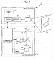
- Fig. 1 is a schematic configuration diagram that illustrates one example of a substance detection device 1 according to a first embodiment.
- the substance detection device 1 is configured with an illuminating unit 10 and a detection unit 40.
- the substance detection device 1 includes a processing circuit (not illustrated) and a memory (not illustrated), for example.
- the memory records a program for realizing the functions of the illuminating unit 10 and the detection unit 40, for example.
- the processing circuit executes the program and thereby allows the illuminating unit 10 and the detection unit 40 to function.
- Each of the illuminating unit 10 and the detection unit 40 may include the processing circuit. Further, each of the illuminating unit 10 and the detection unit 40 may include the memory. The memory that is included in each of the illuminating unit 10 and the detection unit 40 is also referred to as the memory of the substance detection device 1.
- the illuminating unit 10 irradiates a monitoring range 50 with light at a prescribed wavelength and thereby illuminates the monitoring range 50.
- the detection unit 40 captures an image of the monitoring range 50 illuminated by the illuminating unit 10 and determines whether or not a substance 51 to be detected is present in the monitoring range 50 based on light and shade (lightness) of the captured image.
- the illuminating unit 10 will first be described.
- the illuminating unit 10 exemplified in Fig. 1 includes solid-state light sources 11 a and 11 b, lenses 12a and 12b, a wavelength selective light branching element 13, a scanning unit 14, and an illumination control unit 15.
- the solid-state light sources 11 a and 11b, the lenses 12a and 12b, and the wavelength selective light branching element 13 configure a light source unit.
- the solid-state light source 11a is a light source that emits light at a wavelength ⁇ 1.
- the solid-state light source 11 b is a light source that emits light at a wavelength ⁇ 2.
- the solid-state light sources 11a and 11b are arranged such that a polarization plane of emission light of the solid-state light source 11a becomes parallel with the polarization plane of emission light of the solid-state light source 11 b.
- the wavelength ⁇ 1 and the wavelength ⁇ 2 are different values. For example, a wavelength that the substance 51 is likely to absorb (high absorptance) is set as " ⁇ 1", and a wavelength that the substance 51 is less likely to absorb (low absorptance) than the wavelength ⁇ 1 is set as " ⁇ 2".
- a light emitting diode LED
- a semiconductor laser a super-luminescent diode
- a semiconductor-pumped solid-state laser a semiconductor-pumped solid-state laser
- the solid-state light sources 11 a and 11 b may be individually and independently configured or may be configured by implementing those together on one semiconductor chip. Further, the solid-state light sources 11a and 11b may be a wavelength tunable semiconductor laser that may change the wavelength of produced light by control from the illumination control unit 15, which will be described below, for example.
- the lens 12a receives input of the light at the wavelength ⁇ 1 emitted from the solid-state light source 11 a, makes the light substantially parallel light, and outputs the substantially parallel light to one side of the wavelength selective light branching element 13.
- the lens 12b receives input of the light at the wavelength ⁇ 2 emitted from the solid-state light source 11 b, makes the light substantially parallel light, and outputs the substantially parallel light to another side of the wavelength selective light branching element 13.
- the lenses 12a and 12b may be omitted from the configuration.
- the wavelength selective light branching element 13 has functions of transmitting the light at the wavelength ⁇ 1 and reflecting the light at the wavelength ⁇ 2.
- the wavelength selective light branching element 13 transmits the substantially parallel light at the wavelength ⁇ 1 that is input from the lens 12a to the one side and outputs the substantially parallel light from the other side.
- the wavelength selective light branching element 13 outputs the substantially parallel light at the wavelength ⁇ 2 that is input from the lens 12b to the other side from the other side while changing an angle by reflection.
- a dichroic mirror, a dichroic prism, or the like may be used for the wavelength selective light branching element 13.
- the wavelength selective light branching element 13 may be omitted from the configuration.
- the scanning unit 14 is an optical component that receives input of each of the light emitted from the solid-state light source 11 a (the light at the wavelength ⁇ 1) and the light emitted from the solid-state light source 11 b (the light at the wavelength ⁇ 2) and illuminates the monitoring range 50 by two-dimensional scanning with reflected light.
- the scanning unit 14 is arranged on the light path of the light at the wavelength ⁇ 1 and the light at the wavelength at ⁇ 2.
- a movable mirror such as a galvanometer mirror, a polygon mirror, or a MEMS mirror driven by electromagnetic force or electrostatic force, an acousto-optic deflection element, or the like in related art may be used.
- the scanning unit 14 includes an actuator, which is not illustrated. The actuator changes the direction (inclination) of the movable mirror. The traveling direction of the light reflected by the movable mirror may thereby be changed.
- the actuator may incline the movable mirror in two different directions, for example.
- the actuator adjusts the inclination angle of the movable mirror and may thereby guide the reflected light to a prescribed area in the monitoring range 50.
- the area illuminated by the reflected light is moved (or scanned) by adjusting the inclination angle of the movable mirror, and whole the monitoring range 50 may thereby be illuminated.
- the illumination control unit 15 instructs the scanning unit 14 about the inclination angle of the movable mirror in order to guide each of the light at the wavelength ⁇ 1 and the light at the wavelength ⁇ 2 to the monitoring range 50, based on information about the monitoring range 50.
- whole a room to be a monitoring target may beforehand be set as the monitoring range 50, or a portion of the room to be the monitoring target (for example, a floor, a wall, a ceiling, a window, a door, and so forth) may be set as the monitoring range 50.
- the information about the monitoring range 50 may be stored in the memory of the substance detection device 1.
- the illumination control unit 15 drives and controls the solid-state light source 11 a when the monitoring range 50 is irradiated with the light at the wavelength ⁇ 1. Further, the illumination control unit 15 drives and controls the solid-state light source 11 b when the monitoring range 50 is irradiated with the light at the wavelength ⁇ 2.
- the illumination control unit 15 controls scanning by the scanning unit 14, that is, the inclination angle (scanning angle) of the movable mirror so that the monitoring range 50 is two-dimensionally scanned with the irradiating light and whole the monitoring range 50 (or a predetermined portion) is thereby illuminated.
- the illumination control unit 15 outputs information about the light that illuminates the monitoring range 50 to the detection unit 40.
- the information about the light that illuminates the monitoring range 50 is information about the wavelength of light of illumination, information about an area in the monitoring range 50 that is illuminated by the light, information about the amount of the light that illuminates the area, and so forth, for example.
- the information about the area in the monitoring range 50 that is illuminated by the light may be information that indicates the coordinates which correspond to the area illuminated by the light or information about the angle of the movable mirror that is inclined by the scanning unit 14.
- Those pieces of information may be output each time when the wavelength of the light of illumination is changed or each time when the area in the monitoring range 50 that is illuminated by the light is changed. Further, after whole the monitoring range 50 is illuminated by the light at the wavelength ⁇ 1 or by the light at the wavelength ⁇ 2 by scanning by the scanning unit 14, the illumination control unit 15 may output the information about the light that illuminates the monitoring range 50 to the detection unit 40.
- the illumination control unit 15 outputs the information about the light at the wavelength ⁇ 1 that illuminates the monitoring range 50 to the detection unit 40.
- the illumination control unit 15 outputs the information about the light at the wavelength ⁇ 2 that illuminates the monitoring range 50 to the detection unit 40.
- the illumination control unit 15 obtains light and shade information of an image of the monitoring range 50 from the detection unit 40.
- the image of the monitoring range 50 is an image (still image or moving image) in a case where the illuminating unit 10 illuminates the monitoring range 50 with each of the light at the wavelength ⁇ 1 and the light at the wavelength ⁇ 2, for example.
- the light and shade information of the image of the monitoring range 50 is information about the difference in lightness in the image of the monitoring range 50, for example.
- the illumination control unit 15 adjusts the intensities of light output from the solid-state light sources 11 a and 11 b in response to the respective areas illuminated by the light from the solid-state light sources 11 a and 11 b in accordance with the light and shade information of the image of the monitoring range 50.
- the detection unit 40 will next be described.
- the detection unit 40 exemplified in Fig. 1 includes an image-capturing unit 41, an image processing unit 42, and a display unit 43.
- Fig. 1 illustrates a configuration in which the detection unit 40 includes the display unit 43, but the configuration is not limited to this.
- the display unit 43 may physically be separated from the detection unit 40.
- the image-capturing unit 41 is a camera that has an image-capturing element and obtains images by photographing whole (or a predetermined portion of) the monitoring range 50.
- an image-capturing element such as a CCD or CMOS that uses silicon with a wavelength sensitivity band of approximately 350 nm to 1100 nm, an image-capturing element that uses InGaAs with a wavelength sensitivity band of approximately 500 nm to 2600 nm, or the like is possible.
- a wavelength filter that allows only a prescribed wavelength to pass through, a polarizing filter that allows only prescribed polarized light to pass through, or the like may be provided in front of the image-capturing unit 41 in accordance with the use.
- two kinds of wavelength filters may be used while those wavelength filters are switched in accordance with the case where the light at the wavelength ⁇ 1 is allowed to pass through and the case where the light at the wavelength ⁇ 2 is allowed to pass through.
- the output of the solid-state light source is modulated by a certain frequency, and the camera of the image-capturing unit 41 electronically opens and closes a shutter at the certain frequency. Signals that are thereby obtained are integrated, and only the light output by the solid-state light source may thereby be selectively taken in.
- the light at a specific wavelength or the specifically polarized light that is output by the solid-state light source may be received without the filter.
- the modulation frequency of the light output by the solid-state light source is caused to differ from the modulation frequency of the noise light, and only the light output by the solid-state light source may thereby be selectively taken out from the noise light.
- the modulation frequency of sunlight is several Hz or lower
- the modulation frequency of light of a fluorescent lamp is 50 to 60 Hz.
- the light output by the solid-state light source may selectively be obtained by setting the modulation frequency of the solid-state light source to 500 Hz or higher.
- the image-capturing unit 41 obtains respective still images or moving images (hereinafter, simply referred to as image) in a case where the illuminating unit 10 illuminates the monitoring range 50 with the light at the wavelength ⁇ 1 and the light at the wavelength ⁇ 2 from captured images.
- the image-capturing unit 41 may capture an image each time when the scanning unit 14 changes the illuminated areas.
- the image-capturing unit 41 may extract the image of the area that is illuminated by the light at the wavelength ⁇ 1 from captured images and perform a synthesis process. Accordingly, the image in a case where the monitoring range 50 is illuminated by the light at the wavelength ⁇ 1 (first image) may be obtained.
- image processing unit 42 may extract the image of the area that is illuminated by the light at the wavelength ⁇ 1 from captured images and perform a synthesis process, whereby the image in a case where the monitoring range 50 is illuminated by the light at the wavelength ⁇ 1 (first image) may be obtained.
- An image in a case where the illuminating unit 10 illuminates the monitoring range 50 with the light at the wavelength ⁇ 2 (second image) may be obtained by a similar process.
- the image processing unit 42 receives input of each of the first image and the second image that are obtained by the image-capturing unit 41.
- the image processing unit 42 determines whether the lightness in the monitoring range 50 is uniform with respect to each of the first image and the second image in an initialization process, which will be described below.
- the image processing unit 42 acquires the differences between the lightness values of the pixels that correspond to the monitoring range 50 and a predetermined value with respect to the first image, and determines that there is no difference in lightness if the acquired values are in a predetermined value range, otherwise determines that there is difference in lightness. In a case where the determination is made that there is difference in lightness, the image processing unit 42 generates information that indicates that there is difference in lightness (light and shade information).
- the predetermined value and the predetermined value range may arbitrarily be set by a manufacturer of the substance detection device 1 or a monitoring person who uses the substance detection device 1.
- the maximum value of the lightness values of the pixels that correspond to the monitoring range 50 with respect to the first image may be used as the predetermined value, for example.
- the value range is preferably set to a range where it may be determined that there is no difference in lightness in the monitoring range 50, for example.
- the image processing unit 42 acquires the differences between the lightness values of the pixels that correspond to the monitoring range 50 and a predetermined value with respect to the second image, and determines that there is no difference in lightness if the acquired values are in a predetermined value range, otherwise determines that there is difference in lightness. In a case where the determination is made there is difference in lightness, the image processing unit 42 generates information that indicates that there is difference in lightness (light and shade information).
- the predetermined value and the predetermined value range may arbitrarily be set by the manufacturer of the substance detection device 1 or the monitoring person who uses the substance detection device 1.
- the maximum value of the lightness values of the pixels that correspond to the monitoring range 50 with respect to the second image may be used as the predetermined value, for example.
- the value range is preferably set to a range where it may be determined that there is no difference in lightness in the monitoring range 50, for example.
- the image processing unit 42 outputs the light and shade information in the monitoring range 50 with respect to the first image to the illuminating unit 10.
- the illuminating unit 10 adjusts the amount of light in response to the area illuminated by the light at the wavelength ⁇ 1 and in accordance with the light and shade information that corresponds to the first image.
- the lightness in the monitoring range 50 in the first image which is obtained by this adjustment, becomes uniform.
- the image processing unit 42 determines that the lightness in the monitoring range 50 is uniform with respect to the first image, the image processing unit 42 stores the first image as a first reference image in the memory of the substance detection device 1.
- the first reference image is preferably stored in the memory.
- the illuminating unit 10 stores first control information that is used when the first reference image is obtained in the memory of the substance detection device 1.
- the first control information is preferably stored in the memory.
- the first control information includes information about the area to be illuminated by the light at the wavelength ⁇ 1 and information about the intensity of the light at the wavelength ⁇ 1 for illuminating the area, for example.
- the illuminating unit 10 controls the solid-state light source 11 a and the scanning unit 14 by using the first control information and may thereby illuminate the monitoring range 50 with the light at the wavelength ⁇ 1 in the same condition as the condition in which the first reference image is obtained.
- the illuminating unit 10 adjusts the amount of light in response to the area illuminated by the light at the wavelength ⁇ 2 and in accordance with the light and shade information that corresponds to the second image.
- the lightness in the monitoring range 50 in the second image which is obtained by this adjustment, becomes uniform.
- the second image in which the lightness in the monitoring range 50 is uniform is stored as a second reference image in the memory of the substance detection device 1.
- the second reference image is preferably stored in the memory.
- the illuminating unit 10 stores second control information that is used when the second reference image is obtained in the memory.
- the second control information is preferably stored in the memory.
- the second control information includes information about the area to be illuminated by the light at the wavelength ⁇ 2 and information about the intensity of the light at the wavelength ⁇ 2 for illuminating the area, for example.
- the illuminating unit 10 controls the solid-state light source 11 b and the scanning unit 14 by using the second control information and may thereby illuminate the monitoring range 50 with the light at the wavelength ⁇ 2 in the same condition as the condition in which the second reference image is obtained.
- the difference in the lightness or the ratio of the lightness of the pixels in the same position between the first reference image and the second reference image becomes the same value or a value that may be assumed as same, regardless of the position of the pixel.
- This value is used as a threshold value in a process of a flowchart that is explained by using Fig. 5 .
- the image-capturing unit 41 obtains a first actual image in a case where the illuminating unit 10 illuminates the monitoring range 50 with the light at the wavelength ⁇ 1 by using the first control information and a second actual image in a case where the illuminating unit 10 illuminates the monitoring range 50 with the light at the wavelength ⁇ 2 by using the second control information.
- the first actual image is the first image obtained by the image-capturing unit 41 in the substance detection process in a case where the illuminating unit 10 illuminates the monitoring range 50 with the light at the wavelength ⁇ 1 by using the first control information.
- the second actual image is the second image obtained by the image-capturing unit 41 in the substance detection process in a case where the illuminating unit 10 illuminates the monitoring range 50 with the light at the wavelength ⁇ 2 by using the second control information.
- the ratio between the respective intensities of the light at the wavelength ⁇ 1 for illuminating those areas is the same with respect to any area.
- the ratio between the respective intensities of the light at the wavelength ⁇ 2 for illuminating those areas is the same with respect to any area.
- the first ratio and the second ratio are preferably the same.
- the image processing unit 42 thereafter acquires the difference in lightness between two images, which is obtained by comparing the first actual image with the second actual image, and detects the specific substance 51 that is present in the monitoring range 50 based on this difference.
- the difference in lightness between the pixels is a lightness difference or a lightness ratio between the pixels, for example.
- the display unit 43 is an interface that is capable of displaying an image output from the image processing unit 42 (for example, a two-dimensional image whose display mode is changed in response to the difference in lightness).
- the display unit 43 may be a display that is provided in the image processing unit 42 or a display screen of a personal computer or a smart phone, which is separately configured from the image processing unit 42, for example. Further, the image processing unit 42 and the display unit 43 may be connected together by wired or wireless connection.
- Fig. 2 is a diagram that illustrates an example in which the substance detection device 1 is installed in a room.
- whole the room (the floor, the walls, the ceiling, the window, and the door) is set as the monitoring range 50.
- a substance for example, a colorless and transparent substance or water that has the same type color as the background is set as the substance 51 to be detected.
- the substance detection device 1 may not only be installed in an indoor space such as a room but also in an outdoor space.
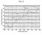
- Fig. 3 is a graph that explains the absorption wavelengths of water.
- the light absorption peaks of water are 1940 nm, 1450 nm, 980 nm, and 740 nm.
- Infrared light at 780 to 900 nm may be used as the light at the wavelength ⁇ 2 so that a person in the room may not perceive the illumination for substance detection.
- the light at such a wavelength is used to detect whether or not water is present in the room (the monitoring range 50) or the part where water is present, as follows:
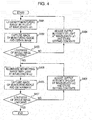
- Fig. 4 is a flowchart that illustrates one example of the initialization process that is executed by the substance detection device 1.
- the substance detection device 1 executes the initialization process before a substance detection process which will be described below. That is, the initialization process is performed before the image-capturing unit 41 obtains the first actual image and the second actual image.
- the initialization process is a process of setting a reference of illumination so that an evaluation result by using the illumination does not contain an error due to factors such as characteristics, an individual difference, and a circumstance of each of the illuminating unit 10, the detection unit 40, and the room (the monitoring range 50).
- the window becomes brighter than the wall due to outside light, and the floor portion on which the light entering from the window shines also becomes brighter than the other floor portions. Further, a portion corresponding to the fluorescent lamp, which is indoor illumination, becomes bright due to light emission.
- the reflectance and absorptance of illumination light change in accordance with the tone or the like of a carpet or a flooring material on the floor or wallpaper.
- the amount of light of reflected light changes when the incident angle of the illumination light changes (in a case where the device is installed in the ceiling, the reflected light from a floor surface is intense, but the reflected light from a wall surface is less intense).
- a camera lens has a characteristic that light captured in a periphery of the field of view is less than the center of the field of view (due to vignetting and the cosine-fourth law).
- the initialization process is performed while the substance 51 is not present in the room (the monitoring range 50).
- the illumination control unit 15 causes the solid-state light source 11a to emit the light at the wavelength ⁇ 1, and the room is illuminated by the light at the wavelength ⁇ 1 (step S401).
- the illuminated room is photographed by the image-capturing unit 41 of the detection unit 40, and the first image is thereby obtained.
- the obtained first image is stored in the memory of the substance detection device 1.
- the first image is preferably stored in the memory (step S402).
- the first image is analyzed by the image processing unit 42, and the light and shade in the first image are recognized.
- step S403 a determination is made whether the lightness of whole the first image is uniform. Specifically, the determination whether the lightness of whole the first image is uniform is made by the above-described analysis.
- the first image is divided into plural areas, and a determination is made whether the differences between the lightness values that correspond to the pixels included in the divided area and a predetermined value fall within a predetermined value range, with respect to each of the plural areas. In a case where the differences between the lightness values that correspond to the pixels and the predetermined value fall within the predetermined value range in any area, a determination is made that the lightness of whole the first image is uniform.
- the monitoring range 50 has a bright part or a dark part.
- the size of each of the areas in the case where the first image is divided into the plural areas is preferably set as the size of the area that may be illuminated by the light at the wavelength ⁇ 1 at a time. This is because in a case where it is determined that a certain area is a dark part, the light intensity may easily be adjusted when the area is illuminated by the light at the wavelength ⁇ 1.
- the image processing unit 42 In a case where a determination is made that the lightness of whole the first image is not uniform (No in step S403), in order to allow the lightness of the captured first image to be uniform lightness in any position in the monitoring range 50, the image processing unit 42 outputs the light and shade information (the coordinates of the bright part or the dark part, the light intensity for illuminating the area that includes the coordinates, and so forth) to the illumination control unit 15.
- the illumination control unit 15 adjusts the output intensity of the solid-state light source 11 a for illuminating the area including the part that is determined to be bright or dark with the light at the wavelength ⁇ 1 based on the received light and shade information, while synchronizing with scanning by the scanning unit 14 (step S404).
- the first control information that is used for this adjustment is stored as setting contents in the memory of the substance detection device 1.
- the first control information is preferably stored in the memory.
- the illumination control unit 15 performs the step S401 with using the first control information after the step S403.
- the image processing unit 42 stores the first image obtained in step S402 as the first reference image in the memory of the substance detection device 1, for example.
- the first reference image is preferably stored in the memory.
- the illumination control unit 15 causes the solid-state light source 11b to emit the light at the wavelength ⁇ 2, and the room is thereby illuminated (step S405).
- the illuminated room is photographed by the image-capturing unit 41 of the detection unit 40, and the second image is thereby obtained.
- the obtained second image is stored in the memory of the substance detection device 1, for example.
- the second image is preferably stored in the memory (step S406).
- the second image is analyzed by the image processing unit 42, and the light and shade in the second image are recognized.
- step S407 a determination is made whether the lightness of whole the second image is uniform. Specifically, the determination whether the lightness of whole the second image is uniform is made by the above-described analysis. This determination is similar to the determination about the first image. Thus, a detailed description will not be made.
- the image processing unit 42 In a case where a determination is made that the lightness of whole the second image is not uniform (No in step S407), in order to allow the lightness of the captured second image to become uniform lightness in any position in the monitoring range 50, the image processing unit 42 outputs the light and shade information (the coordinates of the bright or dark part, the light intensity for illuminating the area that includes the coordinates, and so forth) to the illumination control unit 15.
- the illumination control unit 15 adjusts the output intensity of the solid-state light source 11b for illuminating the area including the part that is determined as bright or dark with the light at the wavelength ⁇ 2 based on the received light and shade information, while synchronizing with scanning by the scanning unit 14 (step S408).
- the second control information that is used for this adjustment is stored as the setting contents in the memory of the substance detection device 1.
- the second control information is preferably stored in the memory.
- the illumination control unit 15 performs step S405 with using the second control information after step S408.
- the image processing unit 42 stores the second image obtained in step S406 as the second reference image in the memory of the substance detection device 1.
- the second reference image is preferably stored in the memory.
- the above-described process allows the lightness values that correspond to the pixels of the first reference image obtained by photographing the room illuminated by the light at the wavelength ⁇ 1 by the image-capturing unit 41 to become the same value.
- the second reference image obtained by photographing the room illuminated by the light at the wavelength ⁇ 2 by the image-capturing unit 41 has the same lightness value in any position in the image. For example, the amount of light of the illumination on the floor portion on which the light entering from the window shines or the portion corresponding to the fluorescent lamp of the indoor illumination is reduced, or the amount of light of the illumination in the periphery of the field of view is increased compared to the center of the field of view of the camera.
- the uniform lightness to obtain is preferably the lightness values that correspond to the pixels of the brightest portions in the first image and the second image. This is for the determination about the presence of the substance 51 to be made by using the darkness of the image. In addition, in order to improve accuracy (resolution) of the determination, it is preferable to obtain uniform lightness by the highest lightness value (or a yet higher value) in the image. Further, it is sufficient that the lightness is uniform with respect to the light at each of the wavelengths. Thus, the uniform lightness in irradiation with the light at the wavelength ⁇ 1 may not necessarily be the same as the uniform lightness in irradiation with the light at the wavelength ⁇ 2.
- the lightness values that correspond to the pixels in the first reference image stored in the memory are the same value or a value that may be assumed to be same.
- the reference value is the same value or a value that may be assumed to be same with respect to the pixel in any position in the monitoring range 50.
- the reference value is stored in the memory of the image processing unit 42.
- the reference value is used as the value for calculating a prescribed threshold value in the substance detection process (step S506), which will be described below and is illustrated in Fig. 5 .
- the substance detection process ( Fig. 5 ) in the room (the monitoring range 50) is executed.
- Fig. 5 is a flowchart that illustrates one example of the substance detection process that is executed by the substance detection device 1.
- the illumination control unit 15 first causes the solid-state light source 11 a to emit the light at the wavelength ⁇ 1, and the room is thereby illuminated by the light at the wavelength ⁇ 1 (step S501).
- the room is illuminated by the light at the wavelength ⁇ 1 in the same condition as the condition in which the first reference image is obtained in the initialization process.
- the illumination control unit 15 may control the solid-state light source and the scanning unit 14 by using first control information stored in the memory.
- An image of the room illuminated by the light at the wavelength ⁇ 1 is photographed by the image-capturing unit 41 of the detection unit 40, and the first actual image is thereby obtained.
- the obtained first actual image is stored in the memory of the substance detection device 1.
- the first actual image is preferably stored in the memory (step S502).
- the illumination control unit 15 causes the solid-state light source 11 b to emit the light at the wavelength ⁇ 2, and the room is thereby illuminated by the light at the wavelength ⁇ 2 (step S503).
- the room is illuminated by the light at the wavelength ⁇ 2 in the same condition as the condition in which the second reference image is obtained in the initialization process.
- second control information stored in the memory may be used.
- An image of the room illuminated by the light at the wavelength ⁇ 2 is photographed by the image-capturing unit 41 of the detection unit 40, and the second actual image is thereby obtained.
- the obtained second actual image is stored in the memory of the substance detection device 1.
- the second actual image is preferably stored in the memory (step S504).
- the first actual image and the second actual image that are stored in the memory are divided into respective predetermined areas by the image processing unit 42.
- the image processing unit 42 identifies one area in the divided areas of the first actual image and a corresponding area in the divided areas of the second actual image.
- the identified area in the first actual image and the corresponding area in the second actual image are partial image corresponding to an identical area which is a part of the monitoring range 50.
- the identified area in the first actual image and the corresponding area in the second actual image are compared by the image processing unit 42.
- the difference in lightness (lightness difference or lightness ratio) between the images is thereby calculated (step S505).
- the light at the wavelength ⁇ 1 is likely to be absorbed by water.
- the lightness in a case of illuminating the part where water is present with the light at the wavelength ⁇ 1 becomes lower (that is, darker) than the lightness in a case of illuminating the part where water is not present with the light at the wavelength ⁇ 1.
- the part is expressed darker than the other parts.
- the light at the wavelength ⁇ 2 is less likely to be absorbed.
- the lightness of the part where the water is present is expressed not very differently from the other parts in the second actual image. Accordingly, the difference in lightness between the two images is assessed, and a determination may thereby be made whether or not water is present in the room (the monitoring range 50). Further, this determination is performed with respect to each of the predetermined areas, and the part where water is present may thereby be specifically detected.
- the lightness values corresponding to the pixels of the first image, which correspond to the area are subtracted from or divided by the lightness values corresponding to the pixels of the second image, which correspond to the area, and the difference in lightness (lightness difference or lightness ratio) between the two images of the area may thereby be calculated.
- the prescribed threshold value in this case is the reference value, for example.
- the image processing unit 42 determines whether the process in step S506 is performed with respect to all of the plural divided areas in the first actual image (step S509). in a case where the image processing unit 42 determines that the process in step S506 is not performed with respect to all of the plural divided areas in the first actual image (No in step S509), the image processing unit 42 identifies one area in the plural divided areas in the first actual image, for which the process in step S506 is not performed, and corresponding one area in the plural divided areas in the second actual image. And the image processing unit 42 returns to step S505 to determine whether water is present or not with respect to the identified area.
- the image processing unit 42 determines that the process in step S506 is performed with respect to all of the plural divided areas in the first actual image (Yes in step S509), the image processing unit 42 ends the substance detection process illustrated in Fig. 5 .
- the substance detection process the part where water is present in the room (the monitoring range 50) may be identified with high accuracy.
- the image processing unit 42 generates the images of the monitoring range 50 that display the area with the determination that water is present and the area with the determination that water is not present in different display modes as necessary and displays the images on the display unit 43.
- steps S505 to S508 are performed with respect to each of the plural divided areas, and a determination is thereby made whether or not water is present with respect to each of the areas.
- embodiments do not have to be limited to this.
- a determination may thereby be made whether or not water is present with respect to each of the positions that correspond to the pixels. This enables the part where water is present to be identified with higher accuracy.
- the reference value that corresponds to the above-described lightness difference has to be changed in response to the above-described first ratio (or the second ratio).
- the substance detection device 1 compares the first image of the monitoring range 50 that is illuminated by the light at the wavelength ⁇ 1 with the second image of the monitoring range 50 that is illuminated by the light at the wavelength ⁇ 2, acquires the difference in lightness, and performs evaluation.
- a wavelength that the substance 51 to be detected is likely to absorb (the absorption amount is large) is set as the wavelength ⁇ 1
- the wavelength that is less likely to be absorbed (the absorption amount is small) is set as the wavelength ⁇ 2. Accordingly, determinations about presence or absence of the substance 51 and the part where the substance 51 is present may easily be made by using the difference in lightness.
- the substance detection device 1 uses the light at the wavelength that is less likely to be absorbed, other than the absorption wavelengths, in addition to the light at the wavelength that is likely to be absorbed by the substance 51 as a target of a determination about presence or absence.
- the variation (unevenness) in the amount of light due to the shape, the surface roughness, and dirt on the surface of the substance 51 may be corrected by using detection results by the wavelength that is less likely to be absorbed. Accordingly, this method that uses plural wavelengths enables the determinations about presence or absence of the substance 51 and the part where the substance 51 is present to be made with higher accuracy than a case where only the wavelength that the substance 51 is likely to absorb is used.
- a position where it is determined that the substance 51 is present may be notified to the monitoring person via the display unit 43.
- the monitoring person may take measures such as restricting entry to the location where water is spilt and causing a cleaning robot to automatically clean the location where water is spilt.
- colorless and transparent substances and substances that have the same type color as the background for example, oil and fungi
- a certain kind of mineral oil absorbs light at a wavelength of 3450 nm but does not absorb light at a wavelength of 2500 nm
- a certain kind of fungus absorbs light at a wavelength of 405 nm but does not absorb light at a wavelength of 500 nm or higher.
- the wavelengths ⁇ 1 and ⁇ 2 of the light emitted by the solid-state light sources 11 a and 11 b are appropriately set, and oil and fungi may thereby be detected similarly to water.
- the initialization process is performed, and each of the first reference image and the second reference image of the monitoring range 50 thereby obtains uniform lightness.
- This provides an advantage of using only one threshold value for the determination about presence or absence of the substance in the substance detection process.
- plural threshold values may be obtained for the image of the monitoring range 50 (for example, if m x n threshold values that correspond to m x n pixels which configure the image of the monitoring range 50 may be obtained)
- the determination about presence or absence of the substance may be made with an image where lightness is not uniform, and the initialization process illustrated in Fig. 4 may thus be omitted.
- the illuminating unit 10 of the substance detection device 1 the configuration in which the monitoring range 50 is irradiated with the light emitted from the solid-state light sources 11 a and 11 b by the two-dimensional scanning by using the scanning unit 14 is described.
- the light source unit itself that includes the solid-state light sources 11a and 11b, the lenses 12a and 12b, and the wavelength selective light branching element 13 may be moved in two-dimensional directions to illuminate the monitoring range 50 with light.
- Fig. 6 is a schematic configuration diagram that illustrates one example of a substance detection device 2 according to the second embodiment.
- the substance detection device 2 is configured with an illuminating unit 20 and the detection unit 40.
- the illuminating unit 20 exemplified in Fig. 6 includes the solid-state light source 11a, the lens 12a, the scanning unit 14, and an illumination control unit 25.
- the illuminating unit 20 has the configuration in which the solid-state light source 11 b, the lens 12b, and the wavelength selective light branching element 13 are omitted from the illuminating unit 10, which is described in the first embodiment.
- the detection unit 40 exemplified in Fig. 6 includes the image-capturing unit 41, the image processing unit 42, and the display unit 43.
- the solid-state light source 11a is a light source that emits light at a wavelength ⁇ 1.
- the wavelength ⁇ 1 is set to a wavelength that the substance 51 is more likely to absorb than a prescribed value (with high absorptance), for example.
- a light emitting diode (LED), a semiconductor laser, a super-luminescent diode, a semiconductor-pumped solid-state laser, and so forth may be used. Because use of the light emitting diode or the super-luminescent diode leads to a wide light emission wavelength width, the wavelength band may be narrowed by using a filter.
- the lens 12a receives input of the light at the wavelength ⁇ 1 emitted from the solid-state light source 11 a, makes the light substantially parallel light, and outputs the substantially parallel light to the scanning unit 14. In a case where the light emitted from the solid-state light source 11 a is already the substantially parallel light, the lens 12a may be omitted from the configuration.
- the scanning unit 14 is an optical component that receives input of the light emitted from the solid-state light source 11 a and illuminates the monitoring range 50 by two-dimensional scanning with reflected light.
- a galvanometer mirror, a polygon mirror, a MEMS mirror driven by electromagnetic force or electrostatic force, an acousto-optic deflection element, or the like in related art may be used.
- the illumination control unit 25 drives and controls the solid-state light source 11 a when the monitoring range 50 is irradiated with the light at the wavelength ⁇ 1.
- the illumination control unit 25 controls the scanning angle of the scanning unit 14 so that the monitoring range 50 is two-dimensionally scanned with the irradiating light and whole the monitoring range 50 (or a predetermined portion) is thereby illuminated.
- the illumination control unit 25 obtains the light and shade information of an image of the monitoring range 50 from the detection unit 40 and adjusts the intensity of the light emitted from the solid-state light source 11 a as necessary.
- the image-capturing unit 41 is a camera that has an image-capturing element and obtains images by photographing whole (or a predetermined portion of) the monitoring range 50.
- an image-capturing element such as a CCD or CMOS that uses silicon with a wavelength sensitivity band of approximately 350 nm to 1100 nm, an image-capturing element that uses InGaAs with a wavelength sensitivity band of approximately 500 nm to 2600 nm, or the like is possible.
- a wavelength filter that allows only a prescribed wavelength to pass through, a polarizing filter that allows only prescribed polarized light to pass through, or the like may be provided in front of the image-capturing unit 41 in accordance with the use.
- the image-capturing unit 41 obtains an image in a case where the illuminating unit 20 illuminates the monitoring range 50 with the light at the wavelength ⁇ 1 (first image) from captured images.
- the process of obtaining the first image is described in the first embodiment. Thus, a detailed description thereof will not be made here.
- the image processing unit 42 receives input of the first image obtained by the image-capturing unit 41.
- the image processing unit 42 determines whether the lightness in the monitoring range 50 is uniform with respect to the first image in an initialization process, which will be described below. The details of the determination are described in the first embodiment. Thus, a detailed description thereof will not be made here.
- the image processing unit 42 determines that the lightness in the monitoring range 50 is uniform with respect to the first image, the image processing unit 42 stores the first image as an initial image in the memory of the substance detection device 1.
- the initial image is preferably stored in the memory.
- the display unit 43 is an interface that is capable of displaying an image output from the image processing unit 42 (for example, a two-dimensional image whose display mode is changed in response to the difference in lightness).
- the display unit 43 may be a display that is provided in the image processing unit 42 or a display screen of a personal computer or a smart phone, which is separately configured from the image processing unit 42, for example. Further, the image processing unit 42 and the display unit 43 may be connected together by wired or wireless connection.
- the substance detection device 2 is installed in a room.
- detection of whether or not water is present in the room (the monitoring range 50) or of a part where water is present is performed as follows. it is matter of course that the substance detection device 2 may not only be installed in an indoor space such as a room but also in an outdoor space.
- Fig. 7 is a flowchart that illustrates one example of the initialization process that is executed by the substance detection device 2.
- the initialization process is a process of setting a reference of illumination so that an evaluation result by using the illumination does not contain an error due to factors such as characteristics, an individual difference, and a circumstance of each of the illuminating unit 20, the detection unit 40, and the room (the monitoring range 50).
- step S401 to step S404 the substance detection device 1, the illuminating unit 10, and the illumination control unit 15 may be substituted by the substance detection device 2, the illuminating unit 20, and the illumination control unit 25, respectively, in the first embodiment, particularly the contents described with Fig. 4 .
- the substance detection device 1 the illuminating unit 10
- the illumination control unit 15 may be substituted by the substance detection device 2, the illuminating unit 20, and the illumination control unit 25, respectively, in the first embodiment, particularly the contents described with Fig. 4 .
- the image processing unit 42 stores the first image obtained in step S402 as the initial image in the memory of the substance detection device 2, for example (step S705).
- the initial image is preferably stored in the memory.
- the above-described processes allow the initial image obtained by photographing the room illuminated by the light at the wavelength ⁇ 1 by the image-capturing unit 41 to have the same lightness value in any position in the image.
- the uniform lightness to obtain is preferably the highest lightness value among the values indicating lightness that correspond to the pixels included in the captured image of the monitoring range 50. This is for the determination about the presence of the substance 51 to be made by using the darkness of the image. In addition, in order to improve accuracy (resolution) of the determination, it is preferable to obtain uniform lightness by the highest lightness value (or a yet higher value) in the image.
- the image processing unit 42 stores the lightness value that corresponds to any of the pixels included in the initial image as a reference value in the memory.
- the reference value is used in the substance detection process, which will be described below and is illustrated in Fig. 8 .
- the image processing unit 42 obtains an actual image in a case where the illuminating unit 20 illuminates the monitoring range 50 with the light at the wavelength ⁇ 1 by using the first control information.
- the ratio between the respective intensities of the light at the wavelength ⁇ 1 for illuminating those areas is the same with respect to any area.
- the substance detection process in the room (the monitoring range 50) is executed.
- Fig. 8 is a flowchart that illustrates one example of the substance detection process that is executed by the substance detection device 2.
- the illumination control unit 25 causes the solid-state light source 11 a to emit the light at the wavelength ⁇ 1, and the room is thereby illuminated by the light at the wavelength ⁇ 1 (step S501).
- the room is illuminated by the light at the wavelength ⁇ 1 in the same condition as the condition in which the initial image is obtained in the initialization process.
- the illumination control unit 25 may control the solid-state light source 11a and the scanning unit 14 by using first control information stored in the memory.
- An image of the room illuminated by the light at the wavelength ⁇ 1 is photographed by the image-capturing unit 41 of the detection unit 40, and the actual image is thereby obtained.
- the actual image is the first image obtained by the image-capturing unit 41.
- the obtained actual image is stored in the memory of the substance detection device 2.
- the detection unit 40 or the image processing unit 42 includes the memory
- the actual image is preferably stored in the memory (step S802).
- the actual image and the initial image that are stored in the memory are divided into respective predetermined areas by the image processing unit 42.
- the image processing unit 42 identifies one area in the divided areas of the actual image and a corresponding area in the divided areas of the initial image.
- the identified area in the actual image and the corresponding area in the initial image are partial image corresponding to an identical area which is a part of the monitoring range 50.
- the identified area in the actual image and the corresponding area in the initial image are compared by the image processing unit 42.
- the difference in lightness (lightness difference or lightness ratio) between the images is thereby calculated (step S805).
- the light at the wavelength ⁇ 1 is likely to be absorbed by water.
- the lightness in a case of illuminating the part where water is present with the light at the wavelength ⁇ 1 becomes lower (that is, darker) than the lightness in a case of illuminating the part where water is not present with the light at the wavelength ⁇ 1.
- the part is expressed darker than the other parts.
- the difference in lightness (lightness difference or lightness ratio) between the actual image and the initial image is assessed, and a determination may thereby be made whether or not water is present in the room (the monitoring range 50). Further, this determination is performed with respect to each of the predetermined areas, and the part where water is present may thereby be specifically detected.
- the lightness values corresponding to the pixels of the initial image, which are included in the area are subtracted from or divided by the lightness values corresponding to the pixels of the actual image, which are included in the area, and the difference in lightness (lightness difference or lightness ratio) between the two images may thereby be calculated. Then, a determination is made whether the calculated value is a prescribed threshold value or higher (step S806).
- step S806 In a case where all the differences in lightness between the pixels included in the area are the prescribed threshold value or higher (Yes in step S806), a determination is made that water is not present because the light at the wavelength ⁇ 1 is not absorbed but reflected in the area (step S507). In a case where the difference in lightness is lower than the prescribed threshold (No in step S806), a determination is made that water is present because the light at the wavelength ⁇ 1 is absorbed in the area (step S508).
- the prescribed threshold value in this case is 0 in the case of calculating the lightness difference and is 1 in the case of calculating the lightness ratio, for example.
- the image processing unit 42 determines whether the process in step S806 is performed with respect to all of the plural divided areas in the actual image (step S509). In a case where the image processing unit 42 determines that the process in step S806 is not performed with respect to all of the plural divided areas in the actual image (No in step S509), the image processing unit 42 identifies one area in the plural divided areas in the actual image, for which the process in step S806 is not performed, and corresponding one area in the plural divided areas in the initial image. And the image processing unit 42 returns to step S805 to determine whether water is present or not with respect to the identified area.
- the image processing unit 42 determines that the process in step S806 is performed with respect to all of the plural divided areas in the actual image (Yes in step S509), the image processing unit 42 ends the substance detection process illustrated in Fig. 8 .
- the substance detection process the part where water is present in the room (the monitoring range 50) may be identified with high accuracy.
- the image processing unit 42 may not perform a process of dividing the initial image into plural areas because values of lightness of the pixels in the initial image become identical to each other regardless of the position of the pixel. In this case a value of lightness of any one of the pixels in the initial image is referred to as a value of lightness of each of the pixels in the initial image.
- steps S805, S806, S507, and S508 are performed with respect to each of the plural divided areas, and a determination is thereby made whether or not water is present with respect to each of the areas.
- steps S805, S806, S507, and S508 are performed with respect to each of the plural divided areas, and a determination is thereby made whether or not water is present with respect to each of the areas.
- embodiments do not have to be limited to this.
- a determination may thereby be made whether or not water is present with respect to each of the positions that correspond to the pixels. This enables the part where water is present to be identified with higher accuracy.
- the reference value that corresponds to the above-described lightness difference has to be changed in response to the above-described ratio.
- the image processing unit 42 generates the images of the monitoring range 50 that display the area with the determination that water is present and the area with the determination that water is not present in different display modes as necessary and displays the images on the display unit 43.
- the substance detection device 2 compares the actual image of the monitoring range 50 that is illuminated by the light at the wavelength ⁇ 1 with the initial image in a state where the specific substance 51 is not present, acquires the difference in lightness (lightness difference or lightness ratio) between the two images, and performs evaluation.
- a wavelength that the substance 51 to be detected is likely to absorb (the absorption amount is large) is set as the wavelength ⁇ 1, and determinations about presence or absence of the substance 51 and the part where the substance 51 is present may easily be made by using the difference in lightness (lightness difference or lightness ratio).
- colorless and transparent substances and substances that have the same type color as the background for example, oil and fungi, may be detected.
- a certain kind of mineral oil absorbs light at a wavelength of 3450 nm but does not absorb light at a wavelength of 2500 nm
- a certain kind of fungus absorbs light at a wavelength of 405 nm but does not absorb light at a wavelength of 500 nm or higher. Accordingly, the wavelengths ⁇ 1 of the light emitted by the solid-state light source 11 a is appropriately set, and oil and fungi may thereby be detected similarly to water.
- the initialization process is performed, and the initial image of the monitoring range 50 thereby obtains uniform lightness.
- This provides an advantage of using only one threshold value for the determination about presence or absence of the substance in the substance detection process.
- plural threshold values may be obtained for the image of the monitoring range 50 (for example, if m x n threshold values that correspond to m x n pixels which configure the image may be obtained)
- the determination about presence or absence of the substance may be made with an image where lightness is not uniform, and the processes of steps S403 and S404 of the initialization process of Fig. 7 may thus be omitted.
- the illuminating unit 20 of the substance detection device 2 the configuration in which the monitoring range 50 is irradiated with the light emitted from the solid-state light source 11 a by the two-dimensional scanning by using the scanning unit 14 is described.
- the light source unit itself that includes the solid-state light source 11 a and the lens 12a may be moved in two-dimensional directions to illuminate the monitoring range 50 with light.
- the monitoring range 50 whose image is captured by the image-capturing unit 41 may be checked by the monitoring person by the image displayed on the display unit 43.
- Fig. 9 is a diagram that illustrates one example where an image captured by the image-capturing unit 41 is displayed on the display unit 43.
- the monitoring person may designate only "the area for detecting the substance (detection area)" in the monitoring range 50 as a prescribed area while checking the image displayed on the display unit 43.
- the monitoring person may designate a change of the monitoring range 50 so as to set only the detection area as the monitoring range 50 while checking the image displayed on the display unit 43.
- the above-described designation is performed by using an input instrument (not illustrated).
- the input instrument is a keyboard or a mouse, for example.
- the above-described designation may be performed by designating an image displayed on the display.
- the monitoring range 50 is a room
- Information about the prescribed area or the change of the monitoring range 50 that are designated is sent from the terminal device to the substance detection device 1 or 2 and stored in the memory of the substance detection device 1 or 2.
- the detection unit 40 or the image processing unit 42 includes the memory
- the information about the prescribed area or the change of the monitoring range 50 that are designated is preferably stored in the memory.
- the image processing unit 42 uses those pieces of information stored in the memory and thereby performs the substance detection process with respect to only the prescribed area or the changed monitoring range 50. Accordingly, the substance detection process for unnecessary areas may be avoided.
- the information about the prescribed area or the change of the monitoring range 50 that are designated may be output to the illuminating unit 10 or 20. Consequently, the illuminating unit 10 or 20 may illuminate only the detection area or the changed monitoring range 50 with light. This enables power consumption due to unnecessary illumination to be avoided.
- Fig. 10 is a diagram that illustrates one example where the moving body is present in a room in which the substance detection device 1 is installed. The example illustrated by Fig. 10 illustrates a person who is in the room in which the substance detection device 1 is installed as an example of the moving body.
- the detection unit 40 is allowed to include a configuration that is capable of detecting motion, and extraction and tracing of the moving body are performed by using the difference between two images captured at a prescribed time interval. Accordingly, the moving body in the monitoring range 50 may be detected, and the area where the detected moving body is positioned may be specified as the non-detection area (the prescribed area). The image processing unit 42 does not detect whether or not the substance 51 is present with respect to the area specified as the non-detection area.
- Information about the detected moving object is stored in the memory of the substance detection device 1 or 2.
- the detection unit 40 or the image processing unit 42 includes the memory
- the information about the moving body is preferably stored in the memory.
- the image processing unit 42 may choose not to perform the substance detection process in the specified non-detection area by using the information about the moving body. This enables errors due to the moving body to be removed.
- the information about the detected moving body may be output to the illuminating unit 10 or 20. Consequently, the illuminating unit 10 or 20 may choose not to illuminate the non-detection area with light in the substance detection process. This enables power consumption due to unnecessary illumination to be avoided.
- the monitoring range 50 whose image is captured by the image-capturing unit 41 may be checked by the monitoring person by the image displayed on the display unit 43 (see Fig. 9 ).
- the monitoring person may designate the range corresponding to the photodegradation substance as "an area that is not illuminated (non-illuminated area)" while checking the image displayed on the display unit 43.
- the monitoring person may designate a change of the monitoring range 50 so that the monitoring range 50 does not include the non-illuminated area, while checking the image displayed on the display unit 43.
- Information about the range corresponding to the photodegradation substance (the prescribed area) or the changed monitoring range 50 is stored in the memory of the substance detection device 1 or 2.
- the illuminating unit 10 (the illumination control unit 15) or the illuminating unit 20 (the illumination control unit 25) includes the memory
- the information about the range corresponding to the photodegradation substance (the prescribed area) or the changed monitoring range 50 is preferably stored in the memory.
- the illuminating unit 10 or 20 may perform control not to illuminate the non-illuminated area with light based on the information about the range corresponding to the photodegradation substance or the changed monitoring range 50. This enables degradation of the photodegradation substance to be avoided.
- the information about the range corresponding to the photodegradation substance or the changed monitoring range 50 is stored also in the memory of the detection unit 40 or the image processing unit 42, and the non-illuminated area may thereby be processed as the non-detection area. This enables errors due to the photodegradation substance to be removed.
- the monitoring range 50 whose image is captured by the image-capturing unit 41 may be checked by the monitoring person by the image displayed on the display unit 43 (see Fig. 9 ).
- the monitoring person may designate the range corresponding to the specular reflection area or substance as "the area that is not illuminated (non-illuminated area)" while checking the image displayed on the display unit 43.
- the monitoring person may designate a change of the monitoring range 50 so that the monitoring range 50 does not include the non-illuminated area, while checking the image displayed on the display unit 43.
- Information about the specular reflection area or substance is stored in the memory of the substance detection device 1 or 2.
- the illuminating unit 10 the illumination control unit 15
- the illuminating unit 20 the illumination control unit 25
- the information about the range corresponding to the specular reflection area or substance (the prescribed area) or the changed monitoring range 50 is preferably stored in the memory.
- the illuminating unit 10 or 20 performs control not to illuminate the non-illuminated area with light based on the information about the specular reflection area or substance. This enables errors due to the specular reflection area or substance to be removed. Further, the information about the specular reflection area or substance is stored in the memory of the image processing unit 42, and the non-illuminated area may thereby be processed as the non-detection area. This enables errors due to the specular reflection area or substance to be further removed.
- the window may not be illuminated to avoid leakage of illumination or the like.
- the monitoring range 50 whose image is captured by the image-capturing unit 41 may be checked by the monitoring person by the image displayed on the display unit 43 (see Fig. 9 ).
- the monitoring person may designate the range corresponding to the window as "the area that is not illuminated (non-illuminated area)" while checking the image displayed on the display unit 43.
- the monitoring person may designate a change of the monitoring range 50 so that the monitoring range 50 does not include the non-illuminated area, while checking the image displayed on the display unit 43.
- Information about the window is stored in the memory of the substance detection device 1 or 2.
- the illuminating unit 10 the illumination control unit 15
- the illuminating unit 20 the illumination control unit 25
- the information about the window is preferably stored in the memory.
- the illuminating unit 10 or 20 performs control not to illuminate the window with light based on the information about the window. This enables leakage of light from the illuminating unit 10 or 20 from the window to be avoided. Further, the information about the window is stored also in the memory of the image processing unit 42, and the non-illuminated area may thereby be processed as the non-detection area. This enables errors due to the window to be further removed.
- At least plural light sources are used, which emit light at wavelengths at which the respective substances exhibit high absorptance.
- the monitoring range 50 is a room
- the combination of a light source A for detecting water which is spilt on the floor and a light source B for detecting a fungus that attaches to the wall is possible.
- the monitoring range 50 whose image is captured by the image-capturing unit 41 may be checked by the monitoring person by the image displayed on the display unit 43 (see Fig. 9 ).
- the monitoring person may designate the respective areas for detecting the substances or may designate two monitoring ranges 50, while checking the image displayed in the display unit 43.
- Information about the designated areas or the monitoring ranges 50 is stored in the memory of the substance detection device 1 or 2.
- the illuminating unit 10 (the illumination control unit 15) or the illuminating unit 20 (the illumination control unit 25) includes the memory
- the information about the two designated areas or the two monitoring ranges 50 is preferably stored in the memory.
- the illuminating unit 10 (the illumination control unit 15) or the illuminating unit 20 (the illumination control unit 25) may be used in different manners such that only the floor area is illuminated by the light from the light source A and only the wall area is illuminated by the light from the light source B.
- the substance detection device 1 or 2 may be mounted on a traveling object (such as an automobile).
- Fig. 11 is a diagram that illustrates one example where the substance detection device 1 is installed in the automobile 71.
- the first reference image and the second reference image or the initial image in a state where water is not present on the road is in advance generated.
- the substance detection process is executed with respect to the road surface as the monitoring range 50. This enables the monitoring person to know a road surface state during travel almost in real time.
- the relationship between the polarization plane and the reflectance of the illumination light changes in response to the angle at which the light emitted from the illuminating unit 10 is incident on the plane of the monitoring range 50 (incident angle).
- the polarization plane of the illumination light may be changed based on the incident angle of the illumination light on the monitoring range 50.
- the monitoring person understands in which position of the monitoring range 50 (for example, a room) and in which orientation the substance detection device 1 or 2 is mounted (see Fig. 2 ). That is, the monitoring person in advance knows the incident angle in illuminating the monitoring range 50 with light with respect to each area, such as the light incident angle in illuminating the floor surface with light, the light incident angle in illuminating a right wall surface with light, or the light incident angle in illuminating a left wall surface with light.
- the monitoring person controls the polarizing device and may thereby apply the polarization plane corresponding to the incident angle that is in advance known to the illumination light.
- a semiconductor laser that emits linearly polarized light or a light emitting diode or a super-luminescent diode whose emission light is changed to linearly polarized light by an additional polarizing filter is preferably used for the light source.
- the area in the monitoring range 50 whose image may be captured by the image-capturing unit 41, is changed by functions (such as zoom, pan, and tilt) of the camera as the image-capturing unit 41, the area illuminated with light by the illuminating unit 10 may be changed in response to the changed area.
- the scanning unit 14 or the illumination control unit 15 or 25 is controlled such that the illuminating unit 10 illuminates only the central portion with light. This enables power consumption due to unnecessary illumination to be avoided.
- the common illuminating apparatus may be used as the illuminating unit 10 or 20.
- the common illuminating apparatus may usually perform common illumination and perform illumination with light at a detection wavelength only during the substance detection process.
- the elements may be realized by configuring those with hardware such as a dedicated processing circuit or by executing software programs that are suitable for the elements by a general-purpose processing circuit.
- a program execution unit that has a processing circuit such as a CPU or a processor reads out and executes software programs that are recorded in a recording medium such as a hard disk or a semiconductor memory, and the elements may thereby be realized.
- a substance detection device is useful for a case of detecting presence of a specific substance such as water or oil and so forth.
Applications Claiming Priority (1)
| Application Number | Priority Date | Filing Date | Title |
|---|---|---|---|
| JP2014188991 | 2014-09-17 |
Publications (1)
| Publication Number | Publication Date |
|---|---|
| EP2998905A1 true EP2998905A1 (fr) | 2016-03-23 |
Family
ID=54185832
Family Applications (1)
| Application Number | Title | Priority Date | Filing Date |
|---|---|---|---|
| EP15183411.6A Withdrawn EP2998905A1 (fr) | 2014-09-17 | 2015-09-02 | Dispositif de détection de substances |
Country Status (3)
| Country | Link |
|---|---|
| US (1) | US9787907B2 (fr) |
| EP (1) | EP2998905A1 (fr) |
| JP (1) | JP6583725B2 (fr) |
Cited By (1)
| Publication number | Priority date | Publication date | Assignee | Title |
|---|---|---|---|---|
| WO2020023142A1 (fr) * | 2018-07-25 | 2020-01-30 | Microsoft Technology Licensing, Llc | Détection de fluide sur une surface |
Families Citing this family (11)
| Publication number | Priority date | Publication date | Assignee | Title |
|---|---|---|---|---|
| JP6498552B2 (ja) * | 2015-07-15 | 2019-04-10 | 株式会社日立製作所 | 漏油検出システム |
| WO2017100723A1 (fr) * | 2015-12-11 | 2017-06-15 | Lutron Electronics Co., Inc. | Système de commande de charge ayant un capteur de lumière visible |
| US10003713B2 (en) * | 2016-04-06 | 2018-06-19 | Kabushiki Kaisha Toshiba | Image forming method and image forming apparatus comprising a scanner section and a light reflection area determination section |
| JP6775195B2 (ja) * | 2016-04-06 | 2020-10-28 | パナソニックIpマネジメント株式会社 | 検知装置、検知方法及び検知プログラム |
| US20170293814A1 (en) * | 2016-04-07 | 2017-10-12 | Ford Global Technologies, Llc | System and Method for Inspecting Road Surfaces |
| WO2018107182A2 (fr) | 2016-12-09 | 2018-06-14 | Lutron Electronics Co., Inc. | Système de commande de charge à capteur de lumière visible |
| US11036045B2 (en) * | 2017-03-14 | 2021-06-15 | Pioneer Corporation | Display device |
| JP2019057797A (ja) * | 2017-09-20 | 2019-04-11 | パナソニックIpマネジメント株式会社 | 暗視撮像装置 |
| JP7135313B2 (ja) * | 2017-12-13 | 2022-09-13 | 富士電機株式会社 | レーザ式ガス分析計 |
| US10293489B1 (en) * | 2017-12-15 | 2019-05-21 | Ankobot (Shanghai) Smart Technologies Co., Ltd. | Control method and system, and cleaning robot using the same |
| US11941886B2 (en) * | 2021-07-27 | 2024-03-26 | Pixart Imaging Inc. | Object detection method and camera apparatus |
Citations (3)
| Publication number | Priority date | Publication date | Assignee | Title |
|---|---|---|---|---|
| JPH02236787A (ja) | 1989-03-10 | 1990-09-19 | Mitsubishi Electric Corp | 状態変化検知装置 |
| WO2012101430A1 (fr) * | 2011-01-25 | 2012-08-02 | Trw Limited | Procédé servant à traiter des images et appareil |
| JP2014115280A (ja) * | 2012-11-16 | 2014-06-26 | Canon Inc | Oct装置、ss−oct装置及びss−oct像を取得する方法 |
Family Cites Families (14)
| Publication number | Priority date | Publication date | Assignee | Title |
|---|---|---|---|---|
| US4772789A (en) * | 1987-12-28 | 1988-09-20 | Rockwell International Corporation | Leak imaging using differential absorption |
| US5001346A (en) * | 1990-02-26 | 1991-03-19 | Rockwell International Corporation | Leak detection system with background compensation |
| JPH04328449A (ja) | 1991-04-26 | 1992-11-17 | Kao Corp | 水分測定方法および測定装置 |
| JP3776681B2 (ja) * | 2000-06-06 | 2006-05-17 | ホーチキ株式会社 | ガス監視装置 |
| JP2007010584A (ja) | 2005-07-01 | 2007-01-18 | Shiseido Co Ltd | 対象における尿素の量を評価する方法及び装置、対象における尿素及び水分の量を評価する方法及び装置、プログラム、並びにコンピュータ読み取り可能な記録媒体 |
| US7652759B1 (en) * | 2006-02-23 | 2010-01-26 | Rockwell Automation Technologies, Inc. | Industrial device with adaptive optics |
| JP2009122083A (ja) * | 2007-11-15 | 2009-06-04 | Hokkai Bane Kk | 近赤外ledを使用した計量器 |
| EP3885743A1 (fr) * | 2008-06-10 | 2021-09-29 | Xtralis Technologies Ltd | Détection de particules |
| JP2010025622A (ja) | 2008-07-16 | 2010-02-04 | Pola Chem Ind Inc | 皮膚水分量分布の鑑別法、その鑑別装置及びプログラム |
| US8622569B1 (en) * | 2009-07-17 | 2014-01-07 | Musco Corporation | Method, system and apparatus for controlling light distribution using swivel-mount led light sources |
| US8483557B1 (en) * | 2012-01-31 | 2013-07-09 | Hewlett-Packard Development Company, L.P. | Camera flash filter |
| US9110354B2 (en) * | 2012-09-20 | 2015-08-18 | Palo Alto Research Center Incorporated | Steerable illumination source for a compact camera |
| JP6045352B2 (ja) * | 2013-01-10 | 2016-12-14 | アズビル株式会社 | 乾き度分布測定装置及び乾き度分布測定方法 |
| TWI538511B (zh) * | 2014-07-30 | 2016-06-11 | 晶睿通訊股份有限公司 | 適應性補光裝置與方法 |
-
2015
- 2015-09-02 EP EP15183411.6A patent/EP2998905A1/fr not_active Withdrawn
- 2015-09-02 JP JP2015173036A patent/JP6583725B2/ja active Active
- 2015-09-07 US US14/846,938 patent/US9787907B2/en active Active
Patent Citations (3)
| Publication number | Priority date | Publication date | Assignee | Title |
|---|---|---|---|---|
| JPH02236787A (ja) | 1989-03-10 | 1990-09-19 | Mitsubishi Electric Corp | 状態変化検知装置 |
| WO2012101430A1 (fr) * | 2011-01-25 | 2012-08-02 | Trw Limited | Procédé servant à traiter des images et appareil |
| JP2014115280A (ja) * | 2012-11-16 | 2014-06-26 | Canon Inc | Oct装置、ss−oct装置及びss−oct像を取得する方法 |
Non-Patent Citations (1)
| Title |
|---|
| SEON-HWA PARK ET AL: "Organic vapor detection using a color-difference image technique for distributed Bragg reflector structured porous silicon", SENSORS AND ACTUATORS B: CHEMICAL, vol. 147, no. 2, 3 June 2010 (2010-06-03), pages 775 - 779, XP055036064, ISSN: 0925-4005, DOI: 10.1016/j.snb.2010.03.075 * |
Cited By (2)
| Publication number | Priority date | Publication date | Assignee | Title |
|---|---|---|---|---|
| WO2020023142A1 (fr) * | 2018-07-25 | 2020-01-30 | Microsoft Technology Licensing, Llc | Détection de fluide sur une surface |
| US20200036880A1 (en) * | 2018-07-25 | 2020-01-30 | Microsoft Technology Licensing, Llc | Detecting fluid on a surface |
Also Published As
| Publication number | Publication date |
|---|---|
| JP6583725B2 (ja) | 2019-10-02 |
| JP2016065865A (ja) | 2016-04-28 |
| US9787907B2 (en) | 2017-10-10 |
| US20160080625A1 (en) | 2016-03-17 |
Similar Documents
| Publication | Publication Date | Title |
|---|---|---|
| US9787907B2 (en) | Substance detection device | |
| US11403836B2 (en) | Optical overlay device | |
| KR101180027B1 (ko) | 광센서 및 이를 이용한 감지 방법 | |
| JP6406606B2 (ja) | 光沢判定装置および光沢判定方法 | |
| US8836672B2 (en) | System and method for improving machine vision in the presence of ambient light | |
| JP6937735B2 (ja) | レーザ測距及び照明 | |
| KR101691242B1 (ko) | 다중 모드 이미징 | |
| KR101182188B1 (ko) | 적외선 센서 및 이를 이용한 감지 방법 | |
| US10482347B2 (en) | Inspection of the contoured surface of the undercarriage of a motor vehicle | |
| KR20060105569A (ko) | 안전한 눈 검출 | |
| CN107835653B (zh) | 用于处理表面的设备 | |
| KR101296780B1 (ko) | 레이저를 이용한 장애물 감지장치 및 방법. | |
| KR101284268B1 (ko) | 비전시스템의 이미지 품질 향상을 위한 컬러조명 제어방법 | |
| JP2002078683A (ja) | 表面検査装置及び方法 | |
| US9699377B2 (en) | Depth detecting apparatus and method, and gesture detecting apparatus and gesture detecting method | |
| JP2020516879A (ja) | 皮膚光沢の定量的推定のための皮膚光沢測定 | |
| US10063785B2 (en) | Colorimetry method, colorimetry device, spectral measurement method, spectral measurement device and electronic apparatus | |
| US11525917B2 (en) | Distance measuring apparatus which detects optical system abnormality | |
| US11293877B2 (en) | Defect detecting device and defect detecting method | |
| JP7401211B2 (ja) | 外光照度測定機能を備えた測距装置及び外光照度測定方法 | |
| US20190051005A1 (en) | Image depth sensing method and image depth sensing apparatus | |
| KR101341189B1 (ko) | 표면각도 측정 광센서 및 이를 이용한 감지 방법 | |
| JP6508763B2 (ja) | 表面検査装置 | |
| JP7035989B2 (ja) | ディスプレイ装置、判別方法および照射方法 | |
| KR101401395B1 (ko) | 표면각도 측정 광센서 및 이를 이용한 표면각도 및 형상정보 감지방법 |
Legal Events
| Date | Code | Title | Description |
|---|---|---|---|
| PUAI | Public reference made under article 153(3) epc to a published international application that has entered the european phase |
Free format text: ORIGINAL CODE: 0009012 |
|
| AK | Designated contracting states |
Kind code of ref document: A1 Designated state(s): AL AT BE BG CH CY CZ DE DK EE ES FI FR GB GR HR HU IE IS IT LI LT LU LV MC MK MT NL NO PL PT RO RS SE SI SK SM TR |
|
| AX | Request for extension of the european patent |
Extension state: BA ME |
|
| 17P | Request for examination filed |
Effective date: 20160921 |
|
| RBV | Designated contracting states (corrected) |
Designated state(s): AL AT BE BG CH CY CZ DE DK EE ES FI FR GB GR HR HU IE IS IT LI LT LU LV MC MK MT NL NO PL PT RO RS SE SI SK SM TR |
|
| STAA | Information on the status of an ep patent application or granted ep patent |
Free format text: STATUS: EXAMINATION IS IN PROGRESS |
|
| 17Q | First examination report despatched |
Effective date: 20180621 |
|
| STAA | Information on the status of an ep patent application or granted ep patent |
Free format text: STATUS: EXAMINATION IS IN PROGRESS |
|
| STAA | Information on the status of an ep patent application or granted ep patent |
Free format text: STATUS: EXAMINATION IS IN PROGRESS |
|
| STAA | Information on the status of an ep patent application or granted ep patent |
Free format text: STATUS: THE APPLICATION IS DEEMED TO BE WITHDRAWN |
|
| 18D | Application deemed to be withdrawn |
Effective date: 20220608 |