EP2998684A1 - Vorrichtung zur zuführung eines kühlmittels zu einem wärmeübertrager, vorzugsweise für einen abgaskühler eines verbrennungsmotors eines kraftfahrzeuges - Google Patents
Vorrichtung zur zuführung eines kühlmittels zu einem wärmeübertrager, vorzugsweise für einen abgaskühler eines verbrennungsmotors eines kraftfahrzeuges Download PDFInfo
- Publication number
- EP2998684A1 EP2998684A1 EP15184620.1A EP15184620A EP2998684A1 EP 2998684 A1 EP2998684 A1 EP 2998684A1 EP 15184620 A EP15184620 A EP 15184620A EP 2998684 A1 EP2998684 A1 EP 2998684A1
- Authority
- EP
- European Patent Office
- Prior art keywords
- coolant
- connecting piece
- heat exchanger
- exhaust gas
- flow guide
- Prior art date
- Legal status (The legal status is an assumption and is not a legal conclusion. Google has not performed a legal analysis and makes no representation as to the accuracy of the status listed.)
- Granted
Links
- 239000002826 coolant Substances 0.000 title claims abstract description 54
- 238000002485 combustion reaction Methods 0.000 title claims abstract description 16
- 239000012530 fluid Substances 0.000 abstract description 4
- 238000009835 boiling Methods 0.000 description 6
- 238000001816 cooling Methods 0.000 description 4
- 238000009826 distribution Methods 0.000 description 4
- 230000001133 acceleration Effects 0.000 description 2
- 238000004519 manufacturing process Methods 0.000 description 2
- 230000001681 protective effect Effects 0.000 description 2
- 238000007789 sealing Methods 0.000 description 2
- 230000007423 decrease Effects 0.000 description 1
- 230000001419 dependent effect Effects 0.000 description 1
- 238000006073 displacement reaction Methods 0.000 description 1
- 230000000694 effects Effects 0.000 description 1
- 239000003344 environmental pollutant Substances 0.000 description 1
- 239000002245 particle Substances 0.000 description 1
- 230000035515 penetration Effects 0.000 description 1
- 231100000719 pollutant Toxicity 0.000 description 1
- 230000002265 prevention Effects 0.000 description 1
- 230000000630 rising effect Effects 0.000 description 1
- 238000009827 uniform distribution Methods 0.000 description 1
- 238000004804 winding Methods 0.000 description 1
Images


Classifications
-
- F—MECHANICAL ENGINEERING; LIGHTING; HEATING; WEAPONS; BLASTING
- F01—MACHINES OR ENGINES IN GENERAL; ENGINE PLANTS IN GENERAL; STEAM ENGINES
- F01N—GAS-FLOW SILENCERS OR EXHAUST APPARATUS FOR MACHINES OR ENGINES IN GENERAL; GAS-FLOW SILENCERS OR EXHAUST APPARATUS FOR INTERNAL COMBUSTION ENGINES
- F01N3/00—Exhaust or silencing apparatus having means for purifying, rendering innocuous, or otherwise treating exhaust
- F01N3/02—Exhaust or silencing apparatus having means for purifying, rendering innocuous, or otherwise treating exhaust for cooling, or for removing solid constituents of, exhaust
- F01N3/0205—Exhaust or silencing apparatus having means for purifying, rendering innocuous, or otherwise treating exhaust for cooling, or for removing solid constituents of, exhaust using heat exchangers
-
- F—MECHANICAL ENGINEERING; LIGHTING; HEATING; WEAPONS; BLASTING
- F01—MACHINES OR ENGINES IN GENERAL; ENGINE PLANTS IN GENERAL; STEAM ENGINES
- F01N—GAS-FLOW SILENCERS OR EXHAUST APPARATUS FOR MACHINES OR ENGINES IN GENERAL; GAS-FLOW SILENCERS OR EXHAUST APPARATUS FOR INTERNAL COMBUSTION ENGINES
- F01N3/00—Exhaust or silencing apparatus having means for purifying, rendering innocuous, or otherwise treating exhaust
- F01N3/02—Exhaust or silencing apparatus having means for purifying, rendering innocuous, or otherwise treating exhaust for cooling, or for removing solid constituents of, exhaust
- F01N3/04—Exhaust or silencing apparatus having means for purifying, rendering innocuous, or otherwise treating exhaust for cooling, or for removing solid constituents of, exhaust using liquids
-
- F—MECHANICAL ENGINEERING; LIGHTING; HEATING; WEAPONS; BLASTING
- F02—COMBUSTION ENGINES; HOT-GAS OR COMBUSTION-PRODUCT ENGINE PLANTS
- F02M—SUPPLYING COMBUSTION ENGINES IN GENERAL WITH COMBUSTIBLE MIXTURES OR CONSTITUENTS THEREOF
- F02M26/00—Engine-pertinent apparatus for adding exhaust gases to combustion-air, main fuel or fuel-air mixture, e.g. by exhaust gas recirculation [EGR] systems
- F02M26/13—Arrangement or layout of EGR passages, e.g. in relation to specific engine parts or for incorporation of accessories
- F02M26/22—Arrangement or layout of EGR passages, e.g. in relation to specific engine parts or for incorporation of accessories with coolers in the recirculation passage
- F02M26/29—Constructional details of the coolers, e.g. pipes, plates, ribs, insulation or materials
- F02M26/32—Liquid-cooled heat exchangers
-
- F—MECHANICAL ENGINEERING; LIGHTING; HEATING; WEAPONS; BLASTING
- F28—HEAT EXCHANGE IN GENERAL
- F28F—DETAILS OF HEAT-EXCHANGE AND HEAT-TRANSFER APPARATUS, OF GENERAL APPLICATION
- F28F9/00—Casings; Header boxes; Auxiliary supports for elements; Auxiliary members within casings
- F28F9/02—Header boxes; End plates
- F28F9/0246—Arrangements for connecting header boxes with flow lines
- F28F9/0256—Arrangements for coupling connectors with flow lines
- F28F9/0258—Arrangements for coupling connectors with flow lines of quick acting type, e.g. with snap action
-
- F—MECHANICAL ENGINEERING; LIGHTING; HEATING; WEAPONS; BLASTING
- F01—MACHINES OR ENGINES IN GENERAL; ENGINE PLANTS IN GENERAL; STEAM ENGINES
- F01N—GAS-FLOW SILENCERS OR EXHAUST APPARATUS FOR MACHINES OR ENGINES IN GENERAL; GAS-FLOW SILENCERS OR EXHAUST APPARATUS FOR INTERNAL COMBUSTION ENGINES
- F01N2260/00—Exhaust treating devices having provisions not otherwise provided for
- F01N2260/02—Exhaust treating devices having provisions not otherwise provided for for cooling the device
- F01N2260/024—Exhaust treating devices having provisions not otherwise provided for for cooling the device using a liquid
Definitions
- the invention relates to a device for supplying a coolant to a heat exchanger, preferably for an exhaust gas cooler of an internal combustion engine of a motor vehicle, comprising a connecting piece.
- Exhaust coolers as used in motor vehicles, have the task of cooling hot exhaust gas from internal combustion engines, so that this cooled exhaust gas can be mixed back into the intake air. So that the thermodynamic efficiency of the internal combustion engine does not sink too much, a cooling to a low level is desirable.
- This principle is commonly known as cooled exhaust gas recirculation and is used to achieve a reduction of pollutants in the exhaust gas.
- the coolant Due to very high exhaust gas temperatures of the internal combustion engine, the coolant, especially in the area directly behind the gas inlet of the Exhaust gas cooler come to a boil, which can have a negative impact on the life of the exhaust gas cooler. The boiling risk can be counteracted to a limited extent by increasing the coolant throughput. Technically, however, the amount of coolant flowing through the exhaust gas cooler is limited by the coolant-side flow resistance of the exhaust gas cooler.
- a system of a valve and a protective cap in which the valve is connected at one end to a line of a closed fluid circuit.
- a sealing body is arranged between the valve and the protective cap in order to prevent the penetration of dirt particles into the coolant.
- the DE 10 2012 221 325 A1 discloses a winding head cooling, wherein two cooling circuit components, which cool an electric machine, are connected by means of a so-called plug and seal element.
- An embodiment of the invention relates to a device for supplying a coolant in a heat exchanger, preferably in an exhaust gas cooler of an internal combustion engine of a motor vehicle and a Connecting piece, wherein in the interior of the connecting piece a projection-like designed Strömungsleit adopted for the coolant is integrated.
- the connecting piece is advantageously designed as a so-called plug and seal element for use in a coolant connection.
- the flow-guiding device is formed approximately centrally on the inner wall, protruding into an inner space of the connecting piece, with a contour of the flow-guiding device rising in the longitudinal direction of the connecting piece in the direction of the heat exchanger.
- a ski-shaped flow guiding device which terminates on both sides with the connecting piece, generates a diversified coolant guide in the direction of the heat exchanger as well as to the sides within the connecting piece.
- the acceleration of the flow is approximately constant and takes place approximately over the entire length of the connecting piece.
- an axial rise of the contour of the flow guide in the direction of the heat exchanger is linear.
- Such a linear increase of the integrated in the connecting piece flow guide allows constructive connection of a line that can be branched in several directions.
- the axial rise of the contour of the flow guide in the direction of the heat exchanger according to a power function.
- Such a course promotes the constant acceleration of the flow of the coolant and thus reduces the risk of boiling the coolant.
- the axial rise of the contour of the flow guide parabolic.
- the contour of the flow guide in the radial direction of the connecting piece is formed approximately mirror-symmetrical, on both sides to a centrally formed maximum is followed by a curvature to the inner wall of the connecting piece.
- the respective curvature runs from the maximum of the flow concave concave to the inner wall of the connecting piece.
- a connecting piece in a coolant connection allows a particularly space-efficient and optimized connection to the exhaust gas cooler without additional hoses or pipes directly to the internal combustion engine.
- the radial alignment of the contour of the flow-guiding device is dependent on a width of the Fluid circuit containing block determined.
- connection piece has an approximately round cross-section and is arranged directly on the heat exchanger.
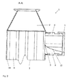
- FIG. 1 shows an inlet region for exhaust gas and coolant of an exhaust gas cooler 1, as used in internal combustion engines, preferably diesel engines, in motor vehicles to cool the hot exhaust gas emitted by the internal combustion engine, so that this cooled exhaust gas can be added to the intake air of the internal combustion engine again.
- an exhaust gas cooler 1 consists of a diffuser 2, to which a radiator block 3 is connected.
- a coolant port 5 is fixed, through which a coolant is introduced into the radiator block 3 to the tubes 4, through which the hot exhaust gas flows to cool.
- the coolant connection 5 is opposite to the radiator block 3 connected to a line not shown.
- connection piece 6 for example, as a plug and seal element, clamped.
- a connection piece 6 is not simply plugged into the coolant connection 5 on the radiator block 3 of the exhaust gas cooler 1, but advantageously and optionally also formed self-sealing, so that no coolant can escape.
- the connecting piece 6 has a round cross section and contains at its Inner wall 7 a flow guide 8.
- the flow guide 8 is designed similar to a projection, and has a maximum in the center 9, which projects into the interior 10 of the connecting piece 6. Starting from the maximum 9, the flow-guiding device 8 has radially formed bulges 11, 12, which extend to the inner wall of the connecting piece 6. These bulges 11, 12 are formed symmetrically to the maximum 9 and are concave.
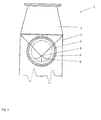
- a section AA of the exhaust gas cooler 1 is in Fig. 2 shown. It can be seen that the coolant connection 5 encloses the connecting piece 6, wherein the flow guide 8 in its axial extent 13, starting from the radiator block 3 of the exhaust gas cooler 1 to the coolant port 5, which is arranged on the internal combustion engine, preferably on the cylinder head of the internal combustion engine, a parabolic Contour, which decreases from the radiator block 3 to the coolant port 5.
- the maximum 9 represents the highest elevation of the flow guide 8, wherein the bulges 11, 12 of the flow guide 8, starting from the radiator block 3 to the coolant connection 5, drop.
- the flow guide 8 is optimized in its radial orientation so that a certain ratio of the width of the coolant block 3 is given to its average width, always to ensure an optimal flow rate of the coolant to the gas flow rate of the exhaust gas cooler 1 and ensure that only a minimal Coolant needs to be provided to prevent the boiling of the coolant.
- Fig. 4 shows an adjustment of the radial average width of the flow guide 8 to the block width of the coolant block 3 of approximately 3.
- Fig. 5 is the coolant distribution adapted to the width of the coolant block 3 in that the block width to the average width of the flow guide 8 is about 2, while at Fig. 6 the block width to the average width is approximately 5.
- the connecting piece 6 is designed so that it extends together with the flow guide 8 approximately to the inner edge of a housing 14 of the coolant block 3 and extends at maximum axial displacement to 2 mm in front of the inner edge of the housing 14.
- the solution described shows a retrofittable coolant connection, in which a flow guide is integrated, which allows compensation of manufacturing tolerances and thermal expansions. The effect depends on the respective intrusion of the flow guide 8 into the connecting piece 6.
Abstract
Description
- Die Erfindung betrifft eine Vorrichtung zur Zuführung eines Kühlmittels zu einem Wärmeübertrager, vorzugsweise für einen Abgaskühler eines Verbrennungsmotors eines Kraftfahrzeuges, umfassend einen Anschlussstutzen.
- Abgaskühler, wie sie in Kraftfahrzeugen verwendet werden, haben die Aufgabe, heißes Abgas von Verbrennungsmotoren zu kühlen, damit dieses gekühlte Abgas der Ansaugluft wieder beigemischt werden kann. Damit der thermodynamische Wirkungsgrad des Verbrennungsmotors nicht zu stark absinkt, ist eine Abkühlung auf ein niedriges Niveau anzustreben. Dieses Prinzip ist allgemein als gekühlte Abgasrückführung bekannt und wird angewandt, um eine Reduzierung von Schadstoffen im Abgas zu erreichen.
- Bedingt durch sehr hohe Abgastemperaturen des Verbrennungsmotors kann das Kühlmittel vor allem in dem Gebiet direkt hinter dem Gaseintritt des Abgaskühlers zum Sieden kommen, was negative Auswirkungen auf die Lebensdauer des Abgaskühlers haben kann. Der Siedegefahr kann in begrenztem Maß durch eine Steigerung des Kühlmitteldurchsatzes entgegengewirkt werden. Technisch ist die Menge des durch den Abgaskühler strömenden Kühlmittels aber durch den kühlmittelseitigen Strömungswiderstand des Abgaskühlers begrenzt.
- Aus der
DE 10 2004 027 479 B3 ist ein System aus einem Ventil und einer Schutzkappe bekannt, bei welchem das Ventil mit einem Ende mit einer Leitung eines geschlossenen Fluidkreislaufes verbunden ist. Zwischen dem Ventil und der Schutzkappe ist dabei ein Dichtkörper angeordnet, um das Eindringen von Schmutzpartikeln in das Kühlmittel zu verhindern. - Die
DE 10 2012 221 325 A1 offenbart eine Wickelkopfkühlung, wobei zwei Kühlkreislaufkomponenten, welche eine elektrische Maschine kühlen, mittels eines so genannten Plug- und Seal-Elementes verbunden sind. - Es ist die Aufgabe der Erfindung, eine Vorrichtung zur Zuführung eines Kühlmittels in einen Wärmeübertrager, vorzugsweise in einen Abgaskühler eines Verbrennungsmotors eines Kraftfahrzeuges, zu schaffen, bei welcher der zur Verfügung stehende Kühlmitteldurchsatz effizient genutzt und eine Siedegefahr des Kühlmittels reduziert wird.
- Diese Aufgabe wird mit einer Vorrichtung nach den Merkmalen von Anspruch 1 gelöst.
- Ein Ausführungsbeispiel der Erfindung betrifft eine Vorrichtung zur Zuführung eines Kühlmittels in einen Wärmeübertrager, vorzugsweise in einen Abgaskühler eines Verbrennungsmotors eines Kraftfahrzeuges und ein Anschlussstutzen, wobei im Inneren des Anschlussstutzens eine vorsprungähnlich gestaltete Strömungsleiteinrichtung für das Kühlmittel integriert ist. Durch eine solche Strömungsleiteinrichtung wird das Kühlmittel schon beim Eintritt in den Wärmeübertrager möglichst gleichmäßig über den Querschnitt der Bestandteile des Wärmeübertragers verteilt, um dann gleich verteilt parallel zwischen den Rohren des Wärmeübertragers, welche das heiße Abgas führen, fließen zu können, wobei die Strömungsleiteinrichtung annähernd mittig an der Innenwandung, in einen Innenraum des Anschlussstutzens hineinragend, ausgebildet ist und eine Kontur der Strömungsleiteinrichtung in einer Längserstreckungsrichtung des Anschlussstutzens in Richtung des Wärmeübertragers ansteigend verläuft. Da diese Gleichverteilung in dem Gebiet direkt hinter dem Eintritt des zu kühlenden Fluids erfolgt, wird eine Siedegefahr des Kühlmittels herabgesetzt. Unter einer Gleichverteilung soll dabei im Weiteren eine gleiche Kühlmittelströmungsgeschwindigkeit des in den Wärmeübertrager einströmenden Kühlmittels verstanden werden.
- Dabei ist der Anschlussstutzen vorteilhaft als so genanntes Plug- und Seal-Element zum Einsatz in einen Kühlmittelanschluss ausgebildet.
- Erfindungsgemäß ist die Strömungsleiteinrichtung annähernd mittig an der Innenwandung, in einen Innenraum des Anschlussstutzens hineinragend, ausgebildet, wobei eine Kontur der Strömungsleiteinrichtung in einer Längserstreckungsrichtung des Anschlussstutzens in Richtung des Wärmeübertragers ansteigend verläuft. Eine solche schanzenförmige Strömungsleiteinrichtung, die zu beiden Seiten mit dem Anschlussstutzen abschließt, erzeugt eine breit gefächerte Kühlmittelführung in Richtung des Wärmeübertragers als auch zu den Seiten innerhalb des Anschlussstutzens. Die Beschleunigung der Strömung erfolgt dabei annähernd konstant und findet etwa über die gesamte Länge des Anschlussstutzens statt.
- In einer Ausgestaltung verläuft ein axialer Anstieg der Kontur der Strömungsleiteinrichtung in Richtung des Wärmeübertragers linear. Ein solcher linearer Anstieg der in den Anschlussstutzen integrierten Strömungsleiteinrichtung ermöglicht konstruktiv den Anschluss von einer Leitung, die in mehrere Richtungen verzweigt werden kann.
- In einer Alternative verläuft der axiale Anstieg der Kontur der Strömungsleiteinrichtung in Richtung des Wärmeübertragers gemäß einer Potenzfunktion. Ein solcher Verlauf unterstützt die konstante Beschleunigung der Strömung des Kühlmittels und verringert somit die Gefahr des Siedens des Kühlmittels.
- In einer Ausführungsform verläuft der axiale Anstieg der Kontur der Strömungsleiteinrichtung parabelförmig. Eine solche Ausgestaltung ermöglicht die Reduzierung des Kühlmittelbedarfes zur Siedevermeidung.
- In einer Variante ist die Kontur der Strömungsleiteinrichtung in radialer Richtung des Anschlussstutzens annähernd spiegelsymmetrisch ausgebildet, wobei beidseitig zu einem mittig ausgebildeten Maximum sich eine Wölbung zur Innenwandung des Anschlussstutzens anschließt. Auch diese Wölbungen unterstützen eine Gleichverteilung der Kühlmittelströmungsgeschwindigkeit.
- Vorteilhafterweise verläuft die jeweilige Wölbung ausgehend von dem Maximum der Strömungsleiteinrichtung konkav zur Innenwandung des Anschlussstutzens. Ein solcher Anschlussstutzen in einem Kühlmittelanschluss ermöglicht einen besonders bauraumeffizienten und optimierten Anschluss an den Abgaskühler ohne zusätzliche Schläuche oder Rohre direkt an den Verbrennungsmotor.
- In einer Weiterbildung ist die radiale Ausrichtung der Kontur der Strömungsleiteinrichtung in Abhängigkeit von einer Breite des, den Fluidkreislauf enthaltenden Blockes bestimmt. Dadurch, dass der Kühlmitteleintritt beim Kühlmittelanschluss schmaler ist als der Block, ergibt sich normalerweise eine glockenförmige Verteilung des Kühlmittels, welches in der Mitte eine hohe Strömungsgeschwindigkeit aufweist, die zu den Seiten abfällt. Diese Unterschiede in der Strömungsgeschwindigkeit werden durch die erfindungsgemäße Vorrichtung abgebaut. Die Strömungsleiteinrichtung verteilt das einströmende Kühlmittel mit einer annähernd konstanten Kühlmittelströmungsgeschwindigkeit.
- In einer Ausgestaltung weist der Anschlussstutzen einen annähernd runden Querschnitt auf und ist direkt an dem Wärmeübertrager angeordnet.
- Weitere vorteilhafte Ausgestaltungen sind durch die nachfolgende Figurenbeschreibung und durch die Unteransprüche beschrieben.
- Nachstehend wird die Erfindung auf der Grundlage zumindest eines Ausführungsbeispiels anhand der Figuren der Zeichnung näher erläutert. Es zeigen:
- Fig. 1
- ein erstes Ausführungsbeispiel der erfindungsgemäßen Vorrichtung am Eintrittsbereich eines Abgaskühlers,
- Fig. 2
- einen Schnitt A-A durch die erfindungsgemäße Vorrichtung und den Eintrittsbereich des Abgaskühlers gemäß
Fig. 1 , - Fig. 3
- einen Schnitt B-B durch die erfindungsgemäße Vorrichtung und den Eintrittsbereich des Abgaskühlers gemäß
Fig. 1 , - Fig. 4
- ein zweites Ausführungsbeispiel der erfindungsgemäßen Vorrichtung am Eintrittsbereich eines Abgaskühlers,
- Fig. 5
- ein drittes Ausführungsbeispiel der erfindungsgemäßen Vorrichtung am Eintrittsbereich eines Abgaskühlers, und
- Fig. 6
- ein viertes Ausführungsbeispiel der erfindungsgemäßen Vorrichtung am Eintrittsbereich eines Abgaskühlers.
-
Figur 1 zeigt einen Eintrittsbereich für Abgas und Kühlmittel eines Abgaskühlers 1, wie er in Verbrennungsmotoren, vorzugsweise Dieselmotoren, in Kraftfahrzeugen eingesetzt wird, um das heiße, von dem Verbrennungsmotor abgegebene Abgas zu kühlen, damit dieses gekühlte Abgas der Ansaugluft des Verbrennungsmotors wieder beigemischt werden kann. Ein solcher Abgaskühler 1 besteht aus einem Diffusor 2, an welchen sich ein Kühlerblock 3 anschließt. Direkt an dem Kühlerblock 3, welcher mehrere parallel zueinander verlaufende Rohre 4 aufweist, in welchen das von dem Verbrennungsmotor erzeugte Abgas geleitet wird, ist ein Kühlmittelanschluss 5 befestigt, durch welchen ein Kühlmittel in den Kühlerblock 3 eingeführt wird, um die Rohre 4, durch welche das heiße Abgas strömt, zu kühlen. Der Kühlmittelanschluss 5 ist entgegengesetzt zum Kühlerblock 3 mit einer nicht weiter dargestellten Leitung verbunden. - In den Kühlmittelanschluss 5 ist ein Anschlussstutzen 6, beispielsweise als Plug- und Seal-Element, geklemmt. Ein solcher Anschlussstutzen 6 ist nicht nur einfach in den Kühlmittelanschluss 5 auf den Kühlerblock 3 des Abgaskühlers 1 einsteckbar, sondern vorteilhaft und optional auch selbstdichtend ausgebildet, so dass kein Kühlmittel austreten kann. Der Anschlussstutzen 6 besitzt einen runden Querschnitt und enthält an seiner Innenwandung 7 eine Strömungsleiteinrichtung 8. Die Strömungsleiteinrichtung 8 ist vorsprungähnlich gestaltet, und weist mittig ein Maximum 9 auf, welches in den Innenraum 10 des Anschlussstutzens 6 hineinragt. Ausgehend von dem Maximum 9 besitzt die Strömungsleiteinrichtung 8 radial ausgebildete Wölbungen 11, 12, die zur Innenwandung des Anschlussstutzens 6 verlaufen. Diese Wölbungen 11, 12 sind dabei zum Maximum 9 symmetrisch ausgebildet und verlaufen konkav.
- Ein Schnitt A-A des Abgaskühlers 1 ist in
Fig. 2 dargestellt. Daraus ist ersichtlich, dass der Kühlmittelanschluss 5 den Anschlussstutzen 6 umschließt, wobei die Strömungsleiteinrichtung 8 in ihrer axialen Erstreckung 13 ausgehend von dem Kühlerblock 3 des Abgaskühlers 1 bis zu dem Kühlmittelanschluss 5, welcher am Verbrennungsmotor, vorzugsweise am Zylinderkopf des Verbrennungsmotor angeordnet ist, eine parabelförmige Kontur aufweist, welche vom Kühlerblock 3 zum Kühlmittelanschluss 5 abnimmt. - Wie aus
Fig. 3 in dem Schnitt B-B ersichtlich ist, stellt das Maximum 9 die höchste Erhebung der Strömungsleiteinrichtung 8 dar, wobei auch die Wölbungen 11, 12 der Strömungsleiteinrichtung 8, ausgehend von dem Kühlerblock 3 zum Kühlmittelanschluss 5, abfallen. - Die Strömungsleiteinrichtung 8 ist in ihrer radialen Ausrichtung so optimiert, dass ein bestimmtes Verhältnis von der Breite des Kühlmittelblockes 3 zu deren Durchschnittsbreite gegeben ist, um jeweils immer eine optimale Strömungsgeschwindigkeit des Kühlmittels gegenüber dem Gasdurchsatz des Abgaskühlers 1 zu gewährleisten und sicherzustellen, dass nur ein minimaler Kühlmittelbedarf zur Vermeidung des Siedens des Kühlmittels zur Verfügung gestellt werden muss.
Fig. 4 zeigt eine Anpassung der radialen Durchschnittsbreite der Strömungsleiteinrichtung 8 zur Blockbreite des Kühlmittelblockes 3 von ungefähr 3. GemäßFig. 5 ist die Kühlmittelverteilung an die Breite des Kühlmittelblockes 3 dahingehend angepasst, dass die Blockbreite zur Durchschnittsbreite der Strömungsleiteinrichtung 8 ungefähr 2 beträgt, während beiFig. 6 die Blockbreite zur Durchschnittsbreite annähernd 5 beträgt. - Der Anschlussstutzen 6 ist so ausgeführt, dass es gemeinsam mit der Strömungsleiteinrichtung 8 etwa bis zur Innenkante eines Gehäuses 14 des Kühlmittelblockes 3 reicht und bei maximaler axialer Verschiebung bis 2 mm vor die Innenkante des Gehäuses 14 reicht. Somit ist ein Ausgleich von Fertigungstoleranzen und thermischer Dehnung möglich, insbesondere dann, wenn es sich noch vorteilhafterweise um 2° kippen lässt.
- Die beschriebene Lösung zeigt einen nachrüstbaren Kühlmittelanschluss, in welchem eine Strömungsleiteinrichtung integriert ist, die einen Ausgleich von Fertigungstoleranzen und thermischen Ausdehnungen ermöglicht. Die Wirkung hängt vom jeweiligen Hineinragen der Strömungsleiteinrichtung 8 in den Anschlussstutzen 6 ab.
Claims (9)
- Vorrichtung zur Zuführung eines Kühlmittels in einen Wärmeübertrager, vorzugsweise Abgaskühler eines Verbrennungsmotors eines Kraftfahrzeuges, umfassend einen Anschlussstutzen (6), dadurch gekennzeichnet, dass der Anschlussstutzen zum Einsatz in einen Kühlmittelanschluss (5) ausgebildet ist, wobei im Inneren des Anschlussstutzens eine vorsprungähnlich gestaltete Strömungsleiteinrichtung (8) für das Kühlmittel integriert ist, wobei die Strömungsleiteinrichtung (8) annähernd mittig an der Innenwandung, in einen Innenraum (10) des Anschlussstutzens (6) hineinragend, ausgebildet ist und eine Kontur der Strömungsleiteinrichtung (8) in einer Längserstreckungsrichtung (13) des Anschlussstutzens (6) in Richtung des Wärmeübertragers ansteigend verläuft.
- Vorrichtung nach Anspruch 1, dadurch gekennzeichnet, dass der Anschlussstutzen als Plug- und Seal-Element ausgebildet ist.
- Vorrichtung nach Anspruch 1 oder 2, dadurch gekennzeichnet, dass ein axialer Anstieg der Kontur der Strömungsleiteinrichtung (8) in Richtung des Wärmeübertragers linear verläuft.
- Vorrichtung nach Anspruch 1 oder 2, dadurch gekennzeichnet, dass der axiale Anstieg der Kontur der Strömungsleiteinrichtung (8) in Richtung des Wärmeübertragers zumindest annähernd gemäß einer Potenzfunktion verläuft.
- Vorrichtung nach Anspruch 4, dadurch gekennzeichnet, dass der axiale Anstieg der Kontur der Strömungsleiteinrichtung (6) parabelförmig verläuft.
- Vorrichtung nach einem der vorhergehenden Ansprüche 1 bis 5, dadurch gekennzeichnet, dass die Kontur der Strömungsleiteinrichtung (8) in radialer Richtung des Anschlussstutzens (6) annähernd spiegelsymmetrisch ausgebildet ist, wobei beidseitig zu einem mittig ausgebildeten Maximum (9) sich je eine Wölbung (11, 12) zur Innenwandung (7) des Anschlussstutzens (6) anschließt.
- Vorrichtung nach Anspruch 6, dadurch gekennzeichnet, dass die jeweilige Wölbung (11, 12) ausgehend von dem Maximum (9) der Strömungsleiteinrichtung (8) konkav zur Innenwandung (7) des Anschlussstutzens (6) verläuft.
- Vorrichtung nach Anspruch 6 oder 7, dadurch gekennzeichnet, dass die radiale Ausrichtung der Kontur der Strömungsleiteinrichtung (8) in Abhängigkeit von einer Breite des Blockes (3) des Wärmeübertragers bestimmt ist.
- Vorrichtung nach einem der vorhergehenden Ansprüche, dadurch gekennzeichnet, dass der Anschlussstutzen (6) einen kreisförmigen oder annähernd runden Querschnitt aufweist und in dem Kühlmittelanschluss (5) eingesetzt ist.
Applications Claiming Priority (1)
| Application Number | Priority Date | Filing Date | Title |
|---|---|---|---|
| DE102014219078.9A DE102014219078A1 (de) | 2014-09-22 | 2014-09-22 | Vorrichtung zur Zuführung eines Kühlmittels zu einem Wärmeübertrager, vorzugsweise für einen Abgaskühler eines Verbrennungsmotors eines Kraftfahrzeuges |
Publications (2)
| Publication Number | Publication Date |
|---|---|
| EP2998684A1 true EP2998684A1 (de) | 2016-03-23 |
| EP2998684B1 EP2998684B1 (de) | 2019-11-06 |
Family
ID=54106217
Family Applications (1)
| Application Number | Title | Priority Date | Filing Date |
|---|---|---|---|
| EP15184620.1A Active EP2998684B1 (de) | 2014-09-22 | 2015-09-10 | Vorrichtung zur zuführung eines kühlmittels zu einem wärmeübertrager, vorzugsweise für einen abgaskühler eines verbrennungsmotors eines kraftfahrzeuges |
Country Status (4)
| Country | Link |
|---|---|
| US (1) | US9708944B2 (de) |
| EP (1) | EP2998684B1 (de) |
| JP (1) | JP2016070654A (de) |
| DE (1) | DE102014219078A1 (de) |
Cited By (2)
| Publication number | Priority date | Publication date | Assignee | Title |
|---|---|---|---|---|
| WO2019072853A1 (de) * | 2017-10-12 | 2019-04-18 | Mahle International Gmbh | Abgaswärmeübertrager |
| EP3567332A1 (de) * | 2018-05-08 | 2019-11-13 | United Technologies Corporation | Wirbelndes zuführrohr für wärmetauscher |
Citations (6)
| Publication number | Priority date | Publication date | Assignee | Title |
|---|---|---|---|---|
| DE1815047A1 (de) * | 1968-12-17 | 1970-06-25 | Internatom Internationale Atom | Verfahren und Vorrichtung zur Gasblasen-Abscheidung aus dem Kuehlmittelstrom eines fluessigkeitsgekuehlten Kernreaktors |
| FR2280953A1 (fr) * | 1974-08-01 | 1976-02-27 | Westinghouse Electric Corp | Reacteur nucleaire dont le coeur est dote d'un dispositif de protection |
| DE102004027479B3 (de) | 2004-06-04 | 2005-09-08 | Contitech Kühner Gmbh & Cie. Kg | System aus einem Ventil und einer Schutzkappe |
| KR100748756B1 (ko) * | 2006-05-11 | 2007-08-13 | 현대자동차주식회사 | 차량용 egr 장치의 egr 쿨러 |
| EP2728155A1 (de) * | 2012-11-06 | 2014-05-07 | BorgWarner Inc. | Wärmetauschervorrichtung zum Austausch von Wärme zwischen Fluiden |
| DE102012221325A1 (de) | 2012-11-22 | 2014-05-22 | Robert Bosch Gmbh | Neuartige Wickelkopf-Kühlung |
Family Cites Families (10)
| Publication number | Priority date | Publication date | Assignee | Title |
|---|---|---|---|---|
| DE1815047U (de) * | 1960-03-11 | 1960-07-21 | Beteiligungs & Patentverw Gmbh | Aus blechgefertigter aufbau fuer lokomotiven. |
| DE29714361U1 (de) * | 1996-08-05 | 1997-12-04 | Vaillant Joh Gmbh & Co | Schichtenspeicher |
| ATE385540T1 (de) * | 2002-05-15 | 2008-02-15 | Behr Gmbh & Co Kg | Abgaswärmetauscher mit ventil |
| DE102005042315A1 (de) * | 2005-09-06 | 2007-03-08 | Behr Gmbh & Co. Kg | Kühlmittelkühler, insbesondere für ein Kraftfahrzeug |
| DE102006051000A1 (de) * | 2005-10-26 | 2007-07-12 | Behr Gmbh & Co. Kg | Wärmetauscher, Verfahren zur Herstellung eines Wärmetauschers |
| JP2007218455A (ja) * | 2006-02-14 | 2007-08-30 | Denso Corp | 熱交換器 |
| US8003059B2 (en) * | 2009-05-18 | 2011-08-23 | R3 Fusion, Inc. | Continuous processing reactors and methods of using same |
| DE102010012192A1 (de) * | 2010-03-19 | 2011-09-22 | Pierburg Gmbh | Kühlmitteleinlassstutzen für einen Wärmetauscher |
| JP5988296B2 (ja) * | 2011-08-10 | 2016-09-07 | 臼井国際産業株式会社 | 多管式熱交換器 |
| DE102014202447A1 (de) * | 2014-02-11 | 2015-08-13 | MAHLE Behr GmbH & Co. KG | Abgaswärmeübertrager |
-
2014
- 2014-09-22 DE DE102014219078.9A patent/DE102014219078A1/de not_active Withdrawn
-
2015
- 2015-09-10 EP EP15184620.1A patent/EP2998684B1/de active Active
- 2015-09-16 JP JP2015183333A patent/JP2016070654A/ja active Pending
- 2015-09-22 US US14/860,783 patent/US9708944B2/en active Active
Patent Citations (6)
| Publication number | Priority date | Publication date | Assignee | Title |
|---|---|---|---|---|
| DE1815047A1 (de) * | 1968-12-17 | 1970-06-25 | Internatom Internationale Atom | Verfahren und Vorrichtung zur Gasblasen-Abscheidung aus dem Kuehlmittelstrom eines fluessigkeitsgekuehlten Kernreaktors |
| FR2280953A1 (fr) * | 1974-08-01 | 1976-02-27 | Westinghouse Electric Corp | Reacteur nucleaire dont le coeur est dote d'un dispositif de protection |
| DE102004027479B3 (de) | 2004-06-04 | 2005-09-08 | Contitech Kühner Gmbh & Cie. Kg | System aus einem Ventil und einer Schutzkappe |
| KR100748756B1 (ko) * | 2006-05-11 | 2007-08-13 | 현대자동차주식회사 | 차량용 egr 장치의 egr 쿨러 |
| EP2728155A1 (de) * | 2012-11-06 | 2014-05-07 | BorgWarner Inc. | Wärmetauschervorrichtung zum Austausch von Wärme zwischen Fluiden |
| DE102012221325A1 (de) | 2012-11-22 | 2014-05-22 | Robert Bosch Gmbh | Neuartige Wickelkopf-Kühlung |
Cited By (3)
| Publication number | Priority date | Publication date | Assignee | Title |
|---|---|---|---|---|
| WO2019072853A1 (de) * | 2017-10-12 | 2019-04-18 | Mahle International Gmbh | Abgaswärmeübertrager |
| US11655745B2 (en) | 2017-10-12 | 2023-05-23 | Mahle International Gmbh | Exhaust gas heat exchanger |
| EP3567332A1 (de) * | 2018-05-08 | 2019-11-13 | United Technologies Corporation | Wirbelndes zuführrohr für wärmetauscher |
Also Published As
| Publication number | Publication date |
|---|---|
| US9708944B2 (en) | 2017-07-18 |
| EP2998684B1 (de) | 2019-11-06 |
| JP2016070654A (ja) | 2016-05-09 |
| DE102014219078A1 (de) | 2016-03-24 |
| US20160084128A1 (en) | 2016-03-24 |
Similar Documents
| Publication | Publication Date | Title |
|---|---|---|
| DE102015109145B4 (de) | Verbrennungsmotorsystem mit Kühlmittel-Steuerventil | |
| EP3108194B1 (de) | Abgaswärmeübertrager | |
| DE102005045103B3 (de) | Kühlvorrichtung für eine Verbrennungskraftmaschine | |
| DE102009043264A1 (de) | Wärmeübertrager | |
| EP2016259B1 (de) | Ölmodul mit integriertem kühlwasserkanal | |
| WO1999045264A1 (de) | Vorrichtung zur kühlung von gasen | |
| DE102014008465A1 (de) | Wärmetauscher, insbesondere Abgaskühler | |
| EP2998684B1 (de) | Vorrichtung zur zuführung eines kühlmittels zu einem wärmeübertrager, vorzugsweise für einen abgaskühler eines verbrennungsmotors eines kraftfahrzeuges | |
| DE102010033125A1 (de) | Wärmetauschereinrichtung | |
| DE102013215234A1 (de) | Ansaugmodul für eine Brennkraftmaschine | |
| DE102015115680A1 (de) | Radiator für ein Fahrzeug | |
| DE102006011727B3 (de) | Kombiniertes Heizungs-/Warmwassersystem für mobile Anwendungen | |
| DE2105657C3 (de) | Wärmetauscher | |
| DE10328458A1 (de) | Niedrigtemperatur-Kühler für ein Kraftfahrzeug zur Kühlung mehrerer Bauteile | |
| EP3135879B1 (de) | Bypass-einrichtung zur reduzierung einer rezirkulation erwärmter luft in eine kühleinrichtung | |
| EP3374620B1 (de) | Brennkraftmaschine | |
| DE102015102096A1 (de) | Wärmetauscher, welcher Abgasrückführungsgas verwendet | |
| EP3309381B1 (de) | Abgasrückführkühler für eine brennkraftmaschine | |
| DE102016113555B4 (de) | Abgas-System für eine Verbrennungskraftmaschine | |
| EP3161402B1 (de) | Wärmeübertrager | |
| DE102012111928A1 (de) | Wärmetauscher für eine Verbrennungskraftmaschine | |
| DE102004036037B4 (de) | Kraftfahrzeug | |
| DE102009035723B3 (de) | Kühlvorrichtung für eine Verbrennungskraftmaschine | |
| DE102010012192A1 (de) | Kühlmitteleinlassstutzen für einen Wärmetauscher | |
| EP3464848B1 (de) | Kühlkörper für ein einspritz-/dosierventil |
Legal Events
| Date | Code | Title | Description |
|---|---|---|---|
| PUAI | Public reference made under article 153(3) epc to a published international application that has entered the european phase |
Free format text: ORIGINAL CODE: 0009012 |
|
| AK | Designated contracting states |
Kind code of ref document: A1 Designated state(s): AL AT BE BG CH CY CZ DE DK EE ES FI FR GB GR HR HU IE IS IT LI LT LU LV MC MK MT NL NO PL PT RO RS SE SI SK SM TR |
|
| AX | Request for extension of the european patent |
Extension state: BA ME |
|
| 17P | Request for examination filed |
Effective date: 20160923 |
|
| RBV | Designated contracting states (corrected) |
Designated state(s): AL AT BE BG CH CY CZ DE DK EE ES FI FR GB GR HR HU IE IS IT LI LT LU LV MC MK MT NL NO PL PT RO RS SE SI SK SM TR |
|
| STAA | Information on the status of an ep patent application or granted ep patent |
Free format text: STATUS: EXAMINATION IS IN PROGRESS |
|
| 17Q | First examination report despatched |
Effective date: 20181005 |
|
| GRAP | Despatch of communication of intention to grant a patent |
Free format text: ORIGINAL CODE: EPIDOSNIGR1 |
|
| STAA | Information on the status of an ep patent application or granted ep patent |
Free format text: STATUS: GRANT OF PATENT IS INTENDED |
|
| INTG | Intention to grant announced |
Effective date: 20190527 |
|
| GRAS | Grant fee paid |
Free format text: ORIGINAL CODE: EPIDOSNIGR3 |
|
| GRAJ | Information related to disapproval of communication of intention to grant by the applicant or resumption of examination proceedings by the epo deleted |
Free format text: ORIGINAL CODE: EPIDOSDIGR1 |
|
| GRAL | Information related to payment of fee for publishing/printing deleted |
Free format text: ORIGINAL CODE: EPIDOSDIGR3 |
|
| STAA | Information on the status of an ep patent application or granted ep patent |
Free format text: STATUS: EXAMINATION IS IN PROGRESS |
|
| GRAR | Information related to intention to grant a patent recorded |
Free format text: ORIGINAL CODE: EPIDOSNIGR71 |
|
| STAA | Information on the status of an ep patent application or granted ep patent |
Free format text: STATUS: GRANT OF PATENT IS INTENDED |
|
| INTC | Intention to grant announced (deleted) | ||
| GRAA | (expected) grant |
Free format text: ORIGINAL CODE: 0009210 |
|
| STAA | Information on the status of an ep patent application or granted ep patent |
Free format text: STATUS: THE PATENT HAS BEEN GRANTED |
|
| INTG | Intention to grant announced |
Effective date: 20190917 |
|
| AK | Designated contracting states |
Kind code of ref document: B1 Designated state(s): AL AT BE BG CH CY CZ DE DK EE ES FI FR GB GR HR HU IE IS IT LI LT LU LV MC MK MT NL NO PL PT RO RS SE SI SK SM TR |
|
| REG | Reference to a national code |
Ref country code: GB Ref legal event code: FG4D Free format text: NOT ENGLISH |
|
| REG | Reference to a national code |
Ref country code: CH Ref legal event code: EP Ref country code: AT Ref legal event code: REF Ref document number: 1199317 Country of ref document: AT Kind code of ref document: T Effective date: 20191115 |
|
| REG | Reference to a national code |
Ref country code: IE Ref legal event code: FG4D Free format text: LANGUAGE OF EP DOCUMENT: GERMAN |
|
| REG | Reference to a national code |
Ref country code: DE Ref legal event code: R096 Ref document number: 502015010836 Country of ref document: DE |
|
| REG | Reference to a national code |
Ref country code: NL Ref legal event code: MP Effective date: 20191106 |
|
| REG | Reference to a national code |
Ref country code: LT Ref legal event code: MG4D |
|
| PG25 | Lapsed in a contracting state [announced via postgrant information from national office to epo] |
Ref country code: SE Free format text: LAPSE BECAUSE OF FAILURE TO SUBMIT A TRANSLATION OF THE DESCRIPTION OR TO PAY THE FEE WITHIN THE PRESCRIBED TIME-LIMIT Effective date: 20191106 Ref country code: LV Free format text: LAPSE BECAUSE OF FAILURE TO SUBMIT A TRANSLATION OF THE DESCRIPTION OR TO PAY THE FEE WITHIN THE PRESCRIBED TIME-LIMIT Effective date: 20191106 Ref country code: NL Free format text: LAPSE BECAUSE OF FAILURE TO SUBMIT A TRANSLATION OF THE DESCRIPTION OR TO PAY THE FEE WITHIN THE PRESCRIBED TIME-LIMIT Effective date: 20191106 Ref country code: LT Free format text: LAPSE BECAUSE OF FAILURE TO SUBMIT A TRANSLATION OF THE DESCRIPTION OR TO PAY THE FEE WITHIN THE PRESCRIBED TIME-LIMIT Effective date: 20191106 Ref country code: BG Free format text: LAPSE BECAUSE OF FAILURE TO SUBMIT A TRANSLATION OF THE DESCRIPTION OR TO PAY THE FEE WITHIN THE PRESCRIBED TIME-LIMIT Effective date: 20200206 Ref country code: FI Free format text: LAPSE BECAUSE OF FAILURE TO SUBMIT A TRANSLATION OF THE DESCRIPTION OR TO PAY THE FEE WITHIN THE PRESCRIBED TIME-LIMIT Effective date: 20191106 Ref country code: NO Free format text: LAPSE BECAUSE OF FAILURE TO SUBMIT A TRANSLATION OF THE DESCRIPTION OR TO PAY THE FEE WITHIN THE PRESCRIBED TIME-LIMIT Effective date: 20200206 Ref country code: PL Free format text: LAPSE BECAUSE OF FAILURE TO SUBMIT A TRANSLATION OF THE DESCRIPTION OR TO PAY THE FEE WITHIN THE PRESCRIBED TIME-LIMIT Effective date: 20191106 Ref country code: GR Free format text: LAPSE BECAUSE OF FAILURE TO SUBMIT A TRANSLATION OF THE DESCRIPTION OR TO PAY THE FEE WITHIN THE PRESCRIBED TIME-LIMIT Effective date: 20200207 Ref country code: PT Free format text: LAPSE BECAUSE OF FAILURE TO SUBMIT A TRANSLATION OF THE DESCRIPTION OR TO PAY THE FEE WITHIN THE PRESCRIBED TIME-LIMIT Effective date: 20200306 |
|
| PG25 | Lapsed in a contracting state [announced via postgrant information from national office to epo] |
Ref country code: HR Free format text: LAPSE BECAUSE OF FAILURE TO SUBMIT A TRANSLATION OF THE DESCRIPTION OR TO PAY THE FEE WITHIN THE PRESCRIBED TIME-LIMIT Effective date: 20191106 Ref country code: RS Free format text: LAPSE BECAUSE OF FAILURE TO SUBMIT A TRANSLATION OF THE DESCRIPTION OR TO PAY THE FEE WITHIN THE PRESCRIBED TIME-LIMIT Effective date: 20191106 Ref country code: IS Free format text: LAPSE BECAUSE OF FAILURE TO SUBMIT A TRANSLATION OF THE DESCRIPTION OR TO PAY THE FEE WITHIN THE PRESCRIBED TIME-LIMIT Effective date: 20200306 |
|
| PG25 | Lapsed in a contracting state [announced via postgrant information from national office to epo] |
Ref country code: AL Free format text: LAPSE BECAUSE OF FAILURE TO SUBMIT A TRANSLATION OF THE DESCRIPTION OR TO PAY THE FEE WITHIN THE PRESCRIBED TIME-LIMIT Effective date: 20191106 |
|
| PG25 | Lapsed in a contracting state [announced via postgrant information from national office to epo] |
Ref country code: CZ Free format text: LAPSE BECAUSE OF FAILURE TO SUBMIT A TRANSLATION OF THE DESCRIPTION OR TO PAY THE FEE WITHIN THE PRESCRIBED TIME-LIMIT Effective date: 20191106 Ref country code: RO Free format text: LAPSE BECAUSE OF FAILURE TO SUBMIT A TRANSLATION OF THE DESCRIPTION OR TO PAY THE FEE WITHIN THE PRESCRIBED TIME-LIMIT Effective date: 20191106 Ref country code: ES Free format text: LAPSE BECAUSE OF FAILURE TO SUBMIT A TRANSLATION OF THE DESCRIPTION OR TO PAY THE FEE WITHIN THE PRESCRIBED TIME-LIMIT Effective date: 20191106 Ref country code: DK Free format text: LAPSE BECAUSE OF FAILURE TO SUBMIT A TRANSLATION OF THE DESCRIPTION OR TO PAY THE FEE WITHIN THE PRESCRIBED TIME-LIMIT Effective date: 20191106 Ref country code: EE Free format text: LAPSE BECAUSE OF FAILURE TO SUBMIT A TRANSLATION OF THE DESCRIPTION OR TO PAY THE FEE WITHIN THE PRESCRIBED TIME-LIMIT Effective date: 20191106 |
|
| REG | Reference to a national code |
Ref country code: DE Ref legal event code: R097 Ref document number: 502015010836 Country of ref document: DE |
|
| PG25 | Lapsed in a contracting state [announced via postgrant information from national office to epo] |
Ref country code: SK Free format text: LAPSE BECAUSE OF FAILURE TO SUBMIT A TRANSLATION OF THE DESCRIPTION OR TO PAY THE FEE WITHIN THE PRESCRIBED TIME-LIMIT Effective date: 20191106 Ref country code: SM Free format text: LAPSE BECAUSE OF FAILURE TO SUBMIT A TRANSLATION OF THE DESCRIPTION OR TO PAY THE FEE WITHIN THE PRESCRIBED TIME-LIMIT Effective date: 20191106 |
|
| PLBE | No opposition filed within time limit |
Free format text: ORIGINAL CODE: 0009261 |
|
| STAA | Information on the status of an ep patent application or granted ep patent |
Free format text: STATUS: NO OPPOSITION FILED WITHIN TIME LIMIT |
|
| 26N | No opposition filed |
Effective date: 20200807 |
|
| PG25 | Lapsed in a contracting state [announced via postgrant information from national office to epo] |
Ref country code: SI Free format text: LAPSE BECAUSE OF FAILURE TO SUBMIT A TRANSLATION OF THE DESCRIPTION OR TO PAY THE FEE WITHIN THE PRESCRIBED TIME-LIMIT Effective date: 20191106 |
|
| PG25 | Lapsed in a contracting state [announced via postgrant information from national office to epo] |
Ref country code: IT Free format text: LAPSE BECAUSE OF FAILURE TO SUBMIT A TRANSLATION OF THE DESCRIPTION OR TO PAY THE FEE WITHIN THE PRESCRIBED TIME-LIMIT Effective date: 20191106 |
|
| PG25 | Lapsed in a contracting state [announced via postgrant information from national office to epo] |
Ref country code: MC Free format text: LAPSE BECAUSE OF FAILURE TO SUBMIT A TRANSLATION OF THE DESCRIPTION OR TO PAY THE FEE WITHIN THE PRESCRIBED TIME-LIMIT Effective date: 20191106 |
|
| REG | Reference to a national code |
Ref country code: CH Ref legal event code: PL |
|
| GBPC | Gb: european patent ceased through non-payment of renewal fee |
Effective date: 20200910 |
|
| REG | Reference to a national code |
Ref country code: BE Ref legal event code: MM Effective date: 20200930 |
|
| PG25 | Lapsed in a contracting state [announced via postgrant information from national office to epo] |
Ref country code: LU Free format text: LAPSE BECAUSE OF NON-PAYMENT OF DUE FEES Effective date: 20200910 |
|
| PG25 | Lapsed in a contracting state [announced via postgrant information from national office to epo] |
Ref country code: FR Free format text: LAPSE BECAUSE OF NON-PAYMENT OF DUE FEES Effective date: 20200930 |
|
| PG25 | Lapsed in a contracting state [announced via postgrant information from national office to epo] |
Ref country code: CH Free format text: LAPSE BECAUSE OF NON-PAYMENT OF DUE FEES Effective date: 20200930 Ref country code: BE Free format text: LAPSE BECAUSE OF NON-PAYMENT OF DUE FEES Effective date: 20200930 Ref country code: GB Free format text: LAPSE BECAUSE OF NON-PAYMENT OF DUE FEES Effective date: 20200910 Ref country code: IE Free format text: LAPSE BECAUSE OF NON-PAYMENT OF DUE FEES Effective date: 20200910 Ref country code: LI Free format text: LAPSE BECAUSE OF NON-PAYMENT OF DUE FEES Effective date: 20200930 |
|
| REG | Reference to a national code |
Ref country code: AT Ref legal event code: MM01 Ref document number: 1199317 Country of ref document: AT Kind code of ref document: T Effective date: 20200910 |
|
| PG25 | Lapsed in a contracting state [announced via postgrant information from national office to epo] |
Ref country code: AT Free format text: LAPSE BECAUSE OF NON-PAYMENT OF DUE FEES Effective date: 20200910 |
|
| PG25 | Lapsed in a contracting state [announced via postgrant information from national office to epo] |
Ref country code: TR Free format text: LAPSE BECAUSE OF FAILURE TO SUBMIT A TRANSLATION OF THE DESCRIPTION OR TO PAY THE FEE WITHIN THE PRESCRIBED TIME-LIMIT Effective date: 20191106 Ref country code: MT Free format text: LAPSE BECAUSE OF FAILURE TO SUBMIT A TRANSLATION OF THE DESCRIPTION OR TO PAY THE FEE WITHIN THE PRESCRIBED TIME-LIMIT Effective date: 20191106 Ref country code: CY Free format text: LAPSE BECAUSE OF FAILURE TO SUBMIT A TRANSLATION OF THE DESCRIPTION OR TO PAY THE FEE WITHIN THE PRESCRIBED TIME-LIMIT Effective date: 20191106 |
|
| PG25 | Lapsed in a contracting state [announced via postgrant information from national office to epo] |
Ref country code: MK Free format text: LAPSE BECAUSE OF FAILURE TO SUBMIT A TRANSLATION OF THE DESCRIPTION OR TO PAY THE FEE WITHIN THE PRESCRIBED TIME-LIMIT Effective date: 20191106 |
|
| PGFP | Annual fee paid to national office [announced via postgrant information from national office to epo] |
Ref country code: DE Payment date: 20230920 Year of fee payment: 9 |