EP2998505A2 - Verfahren zum schweissen einer turboladerwelle mit einer turbinenradanordnung - Google Patents
Verfahren zum schweissen einer turboladerwelle mit einer turbinenradanordnung Download PDFInfo
- Publication number
- EP2998505A2 EP2998505A2 EP15185375.1A EP15185375A EP2998505A2 EP 2998505 A2 EP2998505 A2 EP 2998505A2 EP 15185375 A EP15185375 A EP 15185375A EP 2998505 A2 EP2998505 A2 EP 2998505A2
- Authority
- EP
- European Patent Office
- Prior art keywords
- turbine wheel
- shaft
- weld
- collet
- information
- Prior art date
- Legal status (The legal status is an assumption and is not a legal conclusion. Google has not performed a legal analysis and makes no representation as to the accuracy of the status listed.)
- Granted
Links
Images








Classifications
-
- B—PERFORMING OPERATIONS; TRANSPORTING
- B23—MACHINE TOOLS; METAL-WORKING NOT OTHERWISE PROVIDED FOR
- B23K—SOLDERING OR UNSOLDERING; WELDING; CLADDING OR PLATING BY SOLDERING OR WELDING; CUTTING BY APPLYING HEAT LOCALLY, e.g. FLAME CUTTING; WORKING BY LASER BEAM
- B23K26/00—Working by laser beam, e.g. welding, cutting or boring
- B23K26/02—Positioning or observing the workpiece, e.g. with respect to the point of impact; Aligning, aiming or focusing the laser beam
- B23K26/03—Observing, e.g. monitoring, the workpiece
- B23K26/032—Observing, e.g. monitoring, the workpiece using optical means
-
- B—PERFORMING OPERATIONS; TRANSPORTING
- B23—MACHINE TOOLS; METAL-WORKING NOT OTHERWISE PROVIDED FOR
- B23K—SOLDERING OR UNSOLDERING; WELDING; CLADDING OR PLATING BY SOLDERING OR WELDING; CUTTING BY APPLYING HEAT LOCALLY, e.g. FLAME CUTTING; WORKING BY LASER BEAM
- B23K26/00—Working by laser beam, e.g. welding, cutting or boring
- B23K26/02—Positioning or observing the workpiece, e.g. with respect to the point of impact; Aligning, aiming or focusing the laser beam
- B23K26/03—Observing, e.g. monitoring, the workpiece
- B23K26/034—Observing the temperature of the workpiece
-
- B—PERFORMING OPERATIONS; TRANSPORTING
- B23—MACHINE TOOLS; METAL-WORKING NOT OTHERWISE PROVIDED FOR
- B23K—SOLDERING OR UNSOLDERING; WELDING; CLADDING OR PLATING BY SOLDERING OR WELDING; CUTTING BY APPLYING HEAT LOCALLY, e.g. FLAME CUTTING; WORKING BY LASER BEAM
- B23K26/00—Working by laser beam, e.g. welding, cutting or boring
- B23K26/02—Positioning or observing the workpiece, e.g. with respect to the point of impact; Aligning, aiming or focusing the laser beam
- B23K26/04—Automatically aligning, aiming or focusing the laser beam, e.g. using the back-scattered light
- B23K26/044—Seam tracking
-
- B—PERFORMING OPERATIONS; TRANSPORTING
- B23—MACHINE TOOLS; METAL-WORKING NOT OTHERWISE PROVIDED FOR
- B23K—SOLDERING OR UNSOLDERING; WELDING; CLADDING OR PLATING BY SOLDERING OR WELDING; CUTTING BY APPLYING HEAT LOCALLY, e.g. FLAME CUTTING; WORKING BY LASER BEAM
- B23K26/00—Working by laser beam, e.g. welding, cutting or boring
- B23K26/02—Positioning or observing the workpiece, e.g. with respect to the point of impact; Aligning, aiming or focusing the laser beam
- B23K26/06—Shaping the laser beam, e.g. by masks or multi-focusing
- B23K26/0604—Shaping the laser beam, e.g. by masks or multi-focusing by a combination of beams
-
- B—PERFORMING OPERATIONS; TRANSPORTING
- B23—MACHINE TOOLS; METAL-WORKING NOT OTHERWISE PROVIDED FOR
- B23K—SOLDERING OR UNSOLDERING; WELDING; CLADDING OR PLATING BY SOLDERING OR WELDING; CUTTING BY APPLYING HEAT LOCALLY, e.g. FLAME CUTTING; WORKING BY LASER BEAM
- B23K26/00—Working by laser beam, e.g. welding, cutting or boring
- B23K26/02—Positioning or observing the workpiece, e.g. with respect to the point of impact; Aligning, aiming or focusing the laser beam
- B23K26/06—Shaping the laser beam, e.g. by masks or multi-focusing
- B23K26/067—Dividing the beam into multiple beams, e.g. multi-focusing
- B23K26/0673—Dividing the beam into multiple beams, e.g. multi-focusing into independently operating sub-beams, e.g. beam multiplexing to provide laser beams for several stations
-
- B—PERFORMING OPERATIONS; TRANSPORTING
- B23—MACHINE TOOLS; METAL-WORKING NOT OTHERWISE PROVIDED FOR
- B23K—SOLDERING OR UNSOLDERING; WELDING; CLADDING OR PLATING BY SOLDERING OR WELDING; CUTTING BY APPLYING HEAT LOCALLY, e.g. FLAME CUTTING; WORKING BY LASER BEAM
- B23K26/00—Working by laser beam, e.g. welding, cutting or boring
- B23K26/08—Devices involving relative movement between laser beam and workpiece
- B23K26/0823—Devices involving rotation of the workpiece
-
- B—PERFORMING OPERATIONS; TRANSPORTING
- B23—MACHINE TOOLS; METAL-WORKING NOT OTHERWISE PROVIDED FOR
- B23K—SOLDERING OR UNSOLDERING; WELDING; CLADDING OR PLATING BY SOLDERING OR WELDING; CUTTING BY APPLYING HEAT LOCALLY, e.g. FLAME CUTTING; WORKING BY LASER BEAM
- B23K26/00—Working by laser beam, e.g. welding, cutting or boring
- B23K26/14—Working by laser beam, e.g. welding, cutting or boring using a fluid stream, e.g. a jet of gas, in conjunction with the laser beam; Nozzles therefor
-
- B—PERFORMING OPERATIONS; TRANSPORTING
- B23—MACHINE TOOLS; METAL-WORKING NOT OTHERWISE PROVIDED FOR
- B23K—SOLDERING OR UNSOLDERING; WELDING; CLADDING OR PLATING BY SOLDERING OR WELDING; CUTTING BY APPLYING HEAT LOCALLY, e.g. FLAME CUTTING; WORKING BY LASER BEAM
- B23K26/00—Working by laser beam, e.g. welding, cutting or boring
- B23K26/20—Bonding
- B23K26/21—Bonding by welding
- B23K26/24—Seam welding
- B23K26/28—Seam welding of curved planar seams
-
- B—PERFORMING OPERATIONS; TRANSPORTING
- B23—MACHINE TOOLS; METAL-WORKING NOT OTHERWISE PROVIDED FOR
- B23K—SOLDERING OR UNSOLDERING; WELDING; CLADDING OR PLATING BY SOLDERING OR WELDING; CUTTING BY APPLYING HEAT LOCALLY, e.g. FLAME CUTTING; WORKING BY LASER BEAM
- B23K26/00—Working by laser beam, e.g. welding, cutting or boring
- B23K26/20—Bonding
- B23K26/32—Bonding taking account of the properties of the material involved
- B23K26/323—Bonding taking account of the properties of the material involved involving parts made of dissimilar metallic material
-
- B—PERFORMING OPERATIONS; TRANSPORTING
- B23—MACHINE TOOLS; METAL-WORKING NOT OTHERWISE PROVIDED FOR
- B23K—SOLDERING OR UNSOLDERING; WELDING; CLADDING OR PLATING BY SOLDERING OR WELDING; CUTTING BY APPLYING HEAT LOCALLY, e.g. FLAME CUTTING; WORKING BY LASER BEAM
- B23K31/00—Processes relevant to this subclass, specially adapted for particular articles or purposes, but not covered by any single one of main groups B23K1/00 - B23K28/00
- B23K31/12—Processes relevant to this subclass, specially adapted for particular articles or purposes, but not covered by any single one of main groups B23K1/00 - B23K28/00 relating to investigating the properties, e.g. the weldability, of materials
- B23K31/125—Weld quality monitoring
-
- F—MECHANICAL ENGINEERING; LIGHTING; HEATING; WEAPONS; BLASTING
- F01—MACHINES OR ENGINES IN GENERAL; ENGINE PLANTS IN GENERAL; STEAM ENGINES
- F01D—NON-POSITIVE DISPLACEMENT MACHINES OR ENGINES, e.g. STEAM TURBINES
- F01D5/00—Blades; Blade-carrying members; Heating, heat-insulating, cooling or antivibration means on the blades or the members
- F01D5/02—Blade-carrying members, e.g. rotors
- F01D5/025—Fixing blade carrying members on shafts
-
- B—PERFORMING OPERATIONS; TRANSPORTING
- B23—MACHINE TOOLS; METAL-WORKING NOT OTHERWISE PROVIDED FOR
- B23K—SOLDERING OR UNSOLDERING; WELDING; CLADDING OR PLATING BY SOLDERING OR WELDING; CUTTING BY APPLYING HEAT LOCALLY, e.g. FLAME CUTTING; WORKING BY LASER BEAM
- B23K2101/00—Articles made by soldering, welding or cutting
- B23K2101/001—Turbines
-
- B—PERFORMING OPERATIONS; TRANSPORTING
- B23—MACHINE TOOLS; METAL-WORKING NOT OTHERWISE PROVIDED FOR
- B23K—SOLDERING OR UNSOLDERING; WELDING; CLADDING OR PLATING BY SOLDERING OR WELDING; CUTTING BY APPLYING HEAT LOCALLY, e.g. FLAME CUTTING; WORKING BY LASER BEAM
- B23K2103/00—Materials to be soldered, welded or cut
- B23K2103/02—Iron or ferrous alloys
- B23K2103/04—Steel or steel alloys
- B23K2103/05—Stainless steel
-
- B—PERFORMING OPERATIONS; TRANSPORTING
- B23—MACHINE TOOLS; METAL-WORKING NOT OTHERWISE PROVIDED FOR
- B23K—SOLDERING OR UNSOLDERING; WELDING; CLADDING OR PLATING BY SOLDERING OR WELDING; CUTTING BY APPLYING HEAT LOCALLY, e.g. FLAME CUTTING; WORKING BY LASER BEAM
- B23K2103/00—Materials to be soldered, welded or cut
- B23K2103/18—Dissimilar materials
-
- B—PERFORMING OPERATIONS; TRANSPORTING
- B23—MACHINE TOOLS; METAL-WORKING NOT OTHERWISE PROVIDED FOR
- B23K—SOLDERING OR UNSOLDERING; WELDING; CLADDING OR PLATING BY SOLDERING OR WELDING; CUTTING BY APPLYING HEAT LOCALLY, e.g. FLAME CUTTING; WORKING BY LASER BEAM
- B23K2103/00—Materials to be soldered, welded or cut
- B23K2103/18—Dissimilar materials
- B23K2103/26—Alloys of Nickel and Cobalt and Chromium
-
- F—MECHANICAL ENGINEERING; LIGHTING; HEATING; WEAPONS; BLASTING
- F05—INDEXING SCHEMES RELATING TO ENGINES OR PUMPS IN VARIOUS SUBCLASSES OF CLASSES F01-F04
- F05D—INDEXING SCHEME FOR ASPECTS RELATING TO NON-POSITIVE-DISPLACEMENT MACHINES OR ENGINES, GAS-TURBINES OR JET-PROPULSION PLANTS
- F05D2220/00—Application
- F05D2220/40—Application in turbochargers
-
- F—MECHANICAL ENGINEERING; LIGHTING; HEATING; WEAPONS; BLASTING
- F05—INDEXING SCHEMES RELATING TO ENGINES OR PUMPS IN VARIOUS SUBCLASSES OF CLASSES F01-F04
- F05D—INDEXING SCHEME FOR ASPECTS RELATING TO NON-POSITIVE-DISPLACEMENT MACHINES OR ENGINES, GAS-TURBINES OR JET-PROPULSION PLANTS
- F05D2230/00—Manufacture
- F05D2230/20—Manufacture essentially without removing material
- F05D2230/23—Manufacture essentially without removing material by permanently joining parts together
- F05D2230/232—Manufacture essentially without removing material by permanently joining parts together by welding
- F05D2230/234—Laser welding
Definitions
- variable geometry assembly 129 is shown as being, in part, disposed between the housing assembly 128 and the housing assembly 126.
- a variable geometry assembly may include vanes or other components to vary geometry of passages that lead to a turbine wheel space in the turbine housing assembly 126.
- a variable geometry compressor assembly may be provided.
- a system can include one or more units that can emit a beam or beams where the beam or beams carry energy sufficient to form a weld between a shaft and a turbine wheel.
- the system may act to minimize distortion from pull-back of a first weld spot (e.g., as may occur with a single beam approach to welding).
- a system can include equipmentto measure one or more characteristics of a plasma plume (e.g., size, height, chemical composition, etc.).
- a system can include equipment to relate one or more plasma characteristics to one or more welding parameters, for example, to control welding based at least in part on plasma plume analysis.
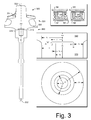
- Fig. 3 shows an example of a SWA 300 that includes a turbine wheel 330 and a shaft 360.
- the turbine wheel 330 includes a nose 332, blades 334, a hub edge 336 and a hub end 340.
- the shaft 360 includes a compressor wheel end 362 and a turbine wheel end 370. As shown, the hub end 340 of the turbine wheel 330 can form a joint with the turbine wheel end 370 of the shaft 360.
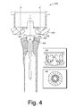
- the collet 430 may include features that provide resiliency.
- Fig. 4 shows an example of a collet 430' that includes a series of gaps between individual extensions that can be brought closer together (e.g., to at least partially close the gaps) via application of force to the collet 430'.
- the collet 430' may contact the hub edge 336 of the turbine wheel 330. Such contact may be forcible contact such that the collet 430' grips the turbine wheel 330 (e.g., clamps the turbine wheel 330).
- the collet 430 may be a spring collet where the centering portion 435 may be adjusted to minimize clearance with the hub edge 336 of the turbine wheel 330 to, for example, contact and optionally forcibly contact the hub edge 336 of the turbine wheel 330.
- Such contact may be forcible contact such that the collet 460' grips the shaft 360 (e.g., clamps the shaft 360).
- the collet 460 may be a spring collet where the centering portion 465 may be adjusted to minimize clearance with the shaft 360 to, for example, contact and optionally forcibly contact the shaft 360.
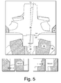
- the hub end 340 of the turbine wheel 330 may contact the turbine wheel end 370 of the shaft 360, under the influence of gravity and/or via applied force.
- a line-of-sight gap exists with respect to a joint formed by the hub end 340 of the turbine wheel 330 and the turbine wheel end 370 of the shaft 360.
- one or more of the collets 430 and 460 may be rotatable such that, for example, the turbine wheel 330 and the shaft 360 may be rotated in unison.
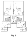
- force may be applied in a manner that acts to diminish clearance or clearances at a joint (e.g., a joint interface, a seam, etc.).
- the force applicator assembly 900 may be controlled to apply force, optionally in a manner responsive to analysis of a joint (e.g., as to one or more points of contact, clearances, etc.).
- a clearance or clearances may be reduced (e.g., seam width reduction, etc.), for example, to reduce beam penetration depth, etc., which may otherwise create damage inside a joint cavity (e.g., by entering the gap or gaps).
- the turbine wheel 330 is clamped by a collet such as the collet 430 (e.g., or the collet 430')
- force applied by a force applicator may be transferred to the collet.
- the collet as clamped to the turbine wheel may travel axially with a turbine wheel.
- a force applicator may be controlled with respect to a minimum force and a maximum force.
- a force may be selected and optionally adjusted based at least in part on one or more desired weld characteristics (e.g., for a SWA unit).
- a method may include adjusting force during a welding process or welding processes (e.g., which may employ multiple beams).
- a maximum force may be based at least in part on limiting run-out level after welding.
- a shaft may include a piloting spigot and a turbine wheel may include a piloting bore.
- a shaft may include a piloting spigot and a turbine wheel may include a piloting bore or, for example, a shaft may be without a piloting spigot and a turbine wheel may be without a piloting bore.
- Fig. 12 shows an example of a method 1210 that includes a locate block 1214 for co-axially locating a turbine wheel and a shaft with a turbine wheel collet and a shaft collet, a rotate block 1218 for rotating the collets, an energize block 1222 for energizing one or more beams, and a weld block 1226 for, via the one or more beams, welding the turbine wheel to the shaft.
- the locate block 1214 may include forming one or more clearances per a block 1215 and/or applying force or forces per a block 1216.
- a force may be an axial force
- a force may be a radial force or forces may include axial and radial forces.
- a collet may be a spring collet that can clamp a component.
- a spring turbine wheel collet may clamp a turbine wheel and a spring shaft collet may clamp a shaft (see, e.g., clamped arrangements of Fig. 4 ).
- a force applicator such as the force applicator 950 may be implemented to apply an axial force to a turbine wheel where such force may be transmitted at least in part to a shaft (e.g., upon contact between the turbine wheel and the shaft).
- the locate block 1254 may include forming one or more clearances per a block 1215 and/or applying one or more forces per a block 1216.
- the shaft collet may apply a radial force to the shaft to clamp the shaft while the force applicator applies an axial force to the turbine wheel where the turbine wheel transfers at least a portion of the force to the shaft.
- the rotate block 1258 may include controlling rotation of the turbine wheel and the shaft in unison via rotation of the shaft collet.
- the weld block 1266 can include cooling per a block 1227. Such cooling may include temperature control via one or more mechanisms such as, for example, via conduction, evaporation, condensation, convection, radiation, etc.
- the system 1300 may include position adjustment mechanisms that can adjust laser associated components in a radial and/or an axial direction with respect to the assembly 400 (e.g., or a portion thereof).
- a focal point, a beam spot, etc. may be adjusted with respect to one or more workpieces such as a turbine wheel and a shaft.
- a beam spot may be positioned to be centered slightly above a joint (e.g., a seam) such that energy is directed more towards the hub end of the turbine wheel.
- a weld pool may be formed that includes more material of the turbine wheel than material of the shaft.
- the turbine wheel may be an alloy that includes nickel whereby a weld pool is formed that includes a concentration of nickel that is greater than a 50/50 mix of the alloy and a material of the shaft.
- a beam spot (e.g., cross-section orthogonal to beam axis) may include a shape such as, for example, a Gaussian shape.
- a beam may include a spot size defined by a diameter or by a radius (e.g., "R").
- a beam may include a beam waist along a beam axis, which may be a minimum spot size.
- the spot size may be defined where contact occurs.
- a beam may include a beam waist that may be offset from where the beam contacts an object (e.g., or objects).
- a welding process can include aligning two or more beams to a seam before welding.
- an intended axial offset from a seam may be imparted such that energy is more directed to a turbine wheel than a shaft (e.g., in a range of about 50 percent to about 80 percent).
- a welding process may operate within multiple beams that are aligned axially within a limit or limits, for example, to maintain weld pool compositions for each weld portion within a limit or limits. Such an approach may act to maintain metallurgical properties of multiple weld pools within one or more property ranges.
- an axial offset limit for the multiple beams may be, for example, less than about 0.1 millimeter.
- the block 1374 may include one or more nozzles that can direct gas toward and/or away from a region generally between the collets.
- the block 1374 may direct gas toward a joint, toward a plasma, etc.
- the block 1374 may act as part of a temperature control mechanism.
- the block 1374 may direct gas via one or more nozzles (e.g., jets) to adjust a temperature of a turbine wheel, a shaft, a turbine wheel and a shaft, etc.
- a nozzle and/or nozzles may rotate, may translate, etc.
- the block 1374 may provide a shielding gas.
- the block 1374 may perform multiple functions.
- Fig. 14 shows an example of a system 1400 that can include multiple branches for multiple beams.
- a single beam unit may generate a beam thatcan be split into multiple beams where each of the beams may be directed via its own beam path.
- a temperature sensor e.g., a back reflection sensor, a plasma sensor and a camera (e.g., a CMOS camera, etc.).
- a sensor such as a temperature sensor, a back reflection sensor or a plasma sensor may operate at sampling rates of the order of about tens of kilohertz.
- a camera sensor may operate at a sampling rate of the order of about a thousand hertz.
- a laser beam may be characterized, for example, by one or more of beam power, beam diameter and beam position of an unfocussed beam, beam diameter and beam position in the focus and polarization of the beam.
- the system 1400 of Fig. 14 may be employed to form the weld regions of the scenario 1500.
- the system 1400 can include various features of the system 1300 of Fig. 13 .
- the controller 1305 may be configured to control the system 1400.
- the controller 1305 may control the beams 810-1 and 810-2 of the scenario 1500 and/or one or more other parameters associated with a welding process (e.g., or welding processes).
- control may include one or more of position control, rotation control, gas control, temperature control, energy control, focal point control, beam spot size control, plasma control, etc.
- Fig. 17 shows an example of a method 1700 that may occur prior to and/or during a welding process (e.g., or welding processes).
- the method 1700 includes an acquisition block 1710 for acquiring information, an analysis block 1720 for analyzing at least a portion of the information, an assessment block 1730 to assess one or more positions (e.g., seam position, axial position, contact position, etc.), a decision block 1740 that decides whether the assessed position or positions are acceptable per an acceptance block 1750 or not acceptable per a rejection and/or adjustment block 1760.
- positions e.g., seam position, axial position, contact position, etc.
- a decision block 1740 that decides whether the assessed position or positions are acceptable per an acceptance block 1750 or not acceptable per a rejection and/or adjustment block 1760.
- the method 1700 may be applied to control one or more aspects of a welding process or welding processes.
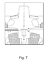
- the method 1700 may acquire images with respect to a joint formed by the hub end 340 of the turbine wheel 330 and the turbine wheel end 370 of the shaft 360. One or more of such images may be analyzed as to clearance, contact, alignment, etc.
- the method 1700 may include adjusting position, force, rotational speed, etc. of the hub end 340 and/or the turbine wheel shaft end 370.
- a beam or beams may be adjusted based at least in part on image analysis.
- beam energy, beam focal length, beam spot size, etc. may be adjusted based on image analysis (e.g., based on one or more of joint clearance, contact, alignment, etc.).
- a method can include seam tracking.
- a method can include gap detection.
- a method can include detecting a seam position by finding a point on a component (e.g., a shaft or a turbine wheel) where the point may be a point that contacts another component (e.g., a turbine wheel or a shaft).
- a "set-up" may be accepted or rejected.
- a rejected "set-up" may be adjusted to reposition one or more components.
- adjusting may include rotating one component while maintaining another component stationary.
- adjusting may include rotating two components to different extents (e.g., one clockwise and the other counter-clockwise).
- information from a plasma or metal plume sensor may pertain to laser power, focus position of a laser beam, gas protection, seam position, welding gap widening, etc.; information from a temperature sensor may pertain to changes in heat dissipation or conduction, for example, due to one or more weld faults (e.g., consider porosity, under penetration, etc.); information from a back reflection sensor may pertain to one or more keyhole characteristics (e.g., welding penetration depth, splatters, etc.); and information from a visible light sensor may pertain to a size, a shape, a surface, a seam, etc. (e.g., consider characteristics of post- and pre- weld regions).
- a system may include one or more interfaces for receiving information and one or more circuits for analyzing information.
- a system may include one or more processors that can perform calculations based at least in part on sensed information to determine whether a welding defect has occurred, optionally in real-time (e.g., or near real-time) with respect to receipt of the information.
- a method can include welding, receiving information pertaining to a weld formed by the welding and analyzing at least a portion of the received information.
- the method may determine, based on the analyzing, if the weld is defective.
- the method may compare at least a portion of received information to other information to determine if a condition (e.g., a quality metric) has been violated. For example, if a weld pool is expected to be greater than a certain dimension and/or less than a certain dimension, deviation from one or more of those dimensions may cause a violation (e.g., indicate that a weld is defective).
- a condition e.g., a quality metric
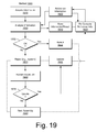
- Fig. 19 shows a method 1900 that includes an acquisition block 1910 for acquiring information (e.g., sensed information, etc.) associated with a welding process, a reference information block 1920 for transmitting reference information, an analysis block 1930 for analyzing at least a portion of the acquired information with respect to at least a portion of the reference information, a storage block 1940 for storing information and/or a result or results of the analysis block 1930, a decision block 1950 for deciding whether a weld formed by the welding process is acceptable, an acceptance block 1952 for accepting a weld formed by the welding process (e.g., two components welded to form a unit, etc.), a rejection block 1954 for rejecting a weld formed by the welding process (e.g., rejecting a unit formed via two welded components), and an update block 1956 for triggering a re-compute block 1958 for re-computing reference information based at least in part on an acceptance per the acceptance block 1952 and/or a rejection per the rejection block 1954.
- the method 1900 may
- the GUI 2000 includes a graphic 2010 with fields that list parameters and associated values, graphics 2022, 2024, 2026 and 2028 that show values of metrics versus position and/or time, and an indicator graphic 2030 that may indicate a status of a weld, an assembly, a component of an assembly, a unit, etc.
- the graphic 2030 may indicate OK, ACCEPT, PASS, etc. via text and/or color (e.g., consider yellow) and/or may indicate NOK, REJECT, NOT PASS, etc. via text and/or color (e.g., consider red).
- the graphic 2030 may provide for a suitable indication, whether text and/or color.
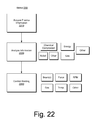
- Fig. 21 shows an example of a method 2100 that includes an acquisition block 2110 for acquiring information, an analysis block 2120 for analyzing information and a control block 2140 for controlling one or more aspects of welding.
- the acquisition block 2110 may acquire information such as, for example, plasma information, temperature information, image information, etc.
- the analysis block 2120 may include analyzing information as to chemical character, physical character and/or one or more other characters.
- the control block 2140 may include controlling one or more beams, force, RPM, gas, temperature and/or one or more other aspects of welding.
- a method can include co-axially locating a turbine wheel and a shaft where a force applicator applies an axially directed force to the turbine wheel, where the turbine wheel transfers at least a portion of the force to shaft and where a rotatable shaft collet supports the shaft; rotating the rotatable shaft collet; energizing at least one laser beam; and via the at least one laser beam, forming a weld between the turbine wheel and the shaft.
- the method may include locating the turbine wheel via a turbine wheel collet.
- a method can include forming a plasma.
- the method may include acquiring information from the plasma and analyzing the information as to a chemical characteristic.
- a method can include controlling at least one parameter responsive to analyzing of information as to a chemical characteristic.
- a method can include acquiring information from a plasma and analyzing the information as to a physical characteristic of the plasma.
- a method may include forming two plasmas. In such an example, the method may include acquiring information from the two plasmas and analyzing the information.
- Such a method may also include controlling at least one parameter responsive to the analyzing of the information (e.g., a welding related parameter, etc.).
- a method can include comparing at least one characteristic of a plasma to at least one characteristic of another of plasma. In such an example, a method can include controlling at least one parameter responsive to the comparing.
- a method can include sensing information about a weld formed between a turbine wheel and a shaft. For example, a method can include analyzing at least a portion of the information to determine quality of the weld. Such a method may include, based at least in part on the quality of the weld, accepting the weld or rejecting the weld.
- a method can include receiving information sensed by a plasma or metal plume sensor and determining at least one member selected from a group consisting of laser beam power, laser beam focus position, gas protection, seam position of a seam formed by two components and welding gap widening.
- a method can include receiving information sensed by a temperature sensor and determining at least one member selected from a group consisting of a change in heat dissipation and a change in heat conduction (e.g., during a welding process, welding processes, etc.).
- the method may include associating a determined change in heat dissipation or a determined change in heat conduction with a faulty weld.
- a fault of a faulty weld may be or include a porosity-based fault and/or a penetration-based fault.
- a method can include performing a welding process, for example, at least in part via energizing at least one beam (e.g., a laser beam, etc.) or, for example, energizing a plurality of laser beams.
- energizing at least one beam e.g., a laser beam, etc.
- energizing a plurality of laser beams e.g., a laser beam, etc.
- a system may provide for formation of a line-of-sight gap between a rotatable turbine wheel centering collet and a rotatable shaft centering collet.
- a system can include a beam splitter that splits a laser beam of a laser beam unit.
- a beam splitter may split a laser beam into two beams.
- a system can include optics that direct spots of two beams (e.g., as optionally split from a common beam) at a joint formed by a turbine wheel and a shaft centered by a rotatable shaft centering collet.
- a system can include a controller that includes circuitry (e.g., hardware, hardware and software, etc.) that can control force applied by a force applicator, rotation of a rotatable shaft centering collet by a drive mechanism, and emission energy of a laser beam unit.
- circuitry e.g., hardware, hardware and software, etc.
- a system can include a plasma or metal plume sensor where a controller of the system can receive information sensed by the plasma or metal plume sensor to determine at least one member selected from a group consisting of laser beam power, laser beam focus position, gas protection, seam position of a seam formed by two components and welding gap widening.
- a system can include a display and controller executable instructions to render a graphical user interface (GUI) to the display.
- GUI graphical user interface
- the GUI can include a quality control graphic that indicates acceptance of a welded unit or rejection of a welded unit.
- a system can include a controller that can control, based at least in part on input to the controller (e.g., via one or more information interfaces), a laser beam unit, a force applicator or a drive mechanism.
- the controller may control one or more optical elements that may provide for splitting a laser beam, aiming a laser beam or laser beams, etc.
- a system can include a turbine wheel clamp.
- a system can include a controller that can control force applied by a force applicator.
- the controller may control force applied by the force applicator to a turbine wheel and/or to a shaft during a welding process.
- a force may be applied by a turbine wheel clamp and/or received by a turbine wheel clamp.
- a turbine wheel clamp may be configured as a nose collet, a hub collet, etc.
- a clamp may be a rotatable clamp.
- a system can include one or more position probes.
- a position probe may be a non-contact probe.
- a position probe may be a contact probe.
- a position probe may determine a position of a portion of a shaft centered by a rotatable shaft centering collet.
- a controller of a system may control a characteristic of a seam formed by a turbine wheel and a shaft based at least in part on a position determined by a position probe. In such an example, the characteristic of the seam may be controlled with respect to a spot size of a laser beam of a laser beam unit.
- a system can include a gas nozzle.
- the system can include a controller that can control delivery of gas via the gas nozzle.
- the system can include a gas flow meter that senses flow of gas to the gas nozzle.
- a gas nozzle may direct gas toward a seam, a weld, a plasma, etc.
Landscapes
- Engineering & Computer Science (AREA)
- Physics & Mathematics (AREA)
- Optics & Photonics (AREA)
- Mechanical Engineering (AREA)
- Plasma & Fusion (AREA)
- General Engineering & Computer Science (AREA)
- Quality & Reliability (AREA)
- Laser Beam Processing (AREA)
- Chemical & Material Sciences (AREA)
- Health & Medical Sciences (AREA)
- Life Sciences & Earth Sciences (AREA)
- Analytical Chemistry (AREA)
- Biochemistry (AREA)
- General Health & Medical Sciences (AREA)
- General Physics & Mathematics (AREA)
- Immunology (AREA)
- Pathology (AREA)
- Spectroscopy & Molecular Physics (AREA)
- Combustion & Propulsion (AREA)
- Supercharger (AREA)
Applications Claiming Priority (1)
| Application Number | Priority Date | Filing Date | Title |
|---|---|---|---|
| US14/488,100 US9827631B2 (en) | 2014-09-16 | 2014-09-16 | Turbocharger shaft and wheel assembly |
Publications (3)
| Publication Number | Publication Date |
|---|---|
| EP2998505A2 true EP2998505A2 (de) | 2016-03-23 |
| EP2998505A3 EP2998505A3 (de) | 2016-07-06 |
| EP2998505B1 EP2998505B1 (de) | 2019-06-05 |
Family
ID=54198941
Family Applications (1)
| Application Number | Title | Priority Date | Filing Date |
|---|---|---|---|
| EP15185375.1A Active EP2998505B1 (de) | 2014-09-16 | 2015-09-15 | Verfahren zum schweissen einer turboladerwelle mit einer turbinenradanordnung |
Country Status (4)
| Country | Link |
|---|---|
| US (1) | US9827631B2 (de) |
| EP (1) | EP2998505B1 (de) |
| KR (1) | KR102429192B1 (de) |
| CN (1) | CN105604682B (de) |
Families Citing this family (11)
| Publication number | Priority date | Publication date | Assignee | Title |
|---|---|---|---|---|
| CN106001923B (zh) * | 2016-06-15 | 2018-06-29 | 湖南天雁机械有限责任公司 | 一种涡轮增压器的涡轮转子激光复合加工方法 |
| DE102016217758B3 (de) * | 2016-09-16 | 2018-01-25 | Technische Universität Dresden | Verfahren und Vorrichtung zur Prozessüberwachung bei einer mittels Kollisionsschweißen gebildeten Schweißnaht |
| CN106363294A (zh) * | 2016-12-07 | 2017-02-01 | 凤城市明晓涡轮增压器制造有限公司 | 一种摩擦焊接用的自动夹紧装置 |
| JP6863334B2 (ja) | 2018-05-11 | 2021-04-21 | 株式会社デンソー | 溶接方法および溶接装置 |
| JP6810110B2 (ja) | 2018-08-24 | 2021-01-06 | ファナック株式会社 | 加工条件調整装置及び機械学習装置 |
| JP6740299B2 (ja) * | 2018-08-24 | 2020-08-12 | ファナック株式会社 | 加工条件調整装置及び機械学習装置 |
| CN114026750B (zh) * | 2019-06-05 | 2025-07-18 | 恩耐公司 | 光纤激光不敏感的瞄准激光器 |
| DE102019210430A1 (de) * | 2019-07-15 | 2021-01-21 | Siemens Aktiengesellschaft | Elektronenstrahlschweißen von Nickelbasis-Superlegierungen und Vorrichtung |
| KR102301173B1 (ko) * | 2021-02-25 | 2021-09-13 | (주)엠프로텍 | 터빈 휠 용접용 지지장치 |
| GB202110597D0 (en) * | 2021-07-23 | 2021-09-08 | Rolls Royce Plc | System and method for welding components |
| KR102593470B1 (ko) * | 2021-08-05 | 2023-10-24 | 진성정밀금속(주) | 터빈 휠과 로터 샤프트의 전자빔 용접시스템 및 방법 |
Family Cites Families (34)
| Publication number | Priority date | Publication date | Assignee | Title |
|---|---|---|---|---|
| FR2574783B1 (fr) | 1984-12-19 | 1991-07-26 | Honda Motor Co Ltd | Dispositif d'assemblage d'un element ceramique a un element metallique, notamment pour turbo-surcompresseurs de moteurs a combustion interne |
| JPS61152902A (ja) | 1984-12-26 | 1986-07-11 | Honda Motor Co Ltd | 軸付きセラミツク製タ−ビン翼車の製造方法 |
| US5248078A (en) | 1992-03-27 | 1993-09-28 | United Technologies Corporation | Inertia bonding of long shafts |
| US5499755A (en) * | 1992-04-17 | 1996-03-19 | Torque Converter Rebuilding Systems, Inc. | Precision alignment welding apparatus |
| JP3293712B2 (ja) | 1994-04-19 | 2002-06-17 | エヌ・ディ・ケー加工センター株式会社 | タービンロータ軸の電子ビーム接合方法 |
| US5651903A (en) | 1995-10-12 | 1997-07-29 | Trw Inc. | Method and apparatus for evaluating laser welding |
| AU6863298A (en) * | 1997-04-04 | 1998-10-30 | Xuan Nguyen-Dinh | Friction welding interlayer and method for joining gamma titanium aluminide to steel, and turbocharger components thereof |
| JP4300663B2 (ja) | 1999-12-24 | 2009-07-22 | 株式会社デンソー | 燃焼圧センサ構造体 |
| JP2001254627A (ja) | 2000-03-13 | 2001-09-21 | Ishikawajima Hanyou Kikai Kk | 過給機のタービンロータ軸の加工方法 |
| JP2002235547A (ja) | 2001-02-09 | 2002-08-23 | Shozo Shimizu | ターボチャージャ用タービン軸の接合方法 |
| GB2392477A (en) | 2002-08-24 | 2004-03-03 | Alstom | Turbocharger |
| EP1459835B1 (de) | 2003-03-15 | 2013-04-24 | TRUMPF Werkzeugmaschinen GmbH + Co. KG | Laserbearbeitungsverfahren mit einem Laserbearbeitungskopf zum Laserschneiden und zum Laserschweissen |
| US7455211B2 (en) | 2003-12-29 | 2008-11-25 | The Boeing Company | Multi-pass friction stir welding |
| US7287960B2 (en) | 2004-07-28 | 2007-10-30 | B{dot over (o)}rgWarner, Inc. | Titanium aluminide wheel and steel shaft connection thereto |
| DE102005027260B4 (de) * | 2005-06-13 | 2007-03-29 | Daimlerchrysler Ag | Verfahren und Vorrichtung zur Qualitätsbestimmung einer Schweißnaht oder einer thermischen Spritzschicht und Verwendung |
| US7156282B1 (en) | 2005-10-11 | 2007-01-02 | Honeywell International, Inc. | Titanium-aluminide turbine wheel and shaft assembly, and method for making same |
| JP2007205253A (ja) | 2006-02-01 | 2007-08-16 | Toyota Motor Corp | タービンロータ、タービン軸およびホイール |
| EP1886757B1 (de) * | 2006-08-07 | 2009-07-01 | LVD Company NV | Anordnung und Verfahren zur On-Line-Überwachung des Laserprozesses eines Werkstückes unter Verwendung eines Wärmekameradetektors und eines Schiefspiegels |
| JP2010512481A (ja) | 2006-12-11 | 2010-04-22 | ボーグワーナー・インコーポレーテッド | ターボチャージャ |
| US20090136368A1 (en) | 2007-11-28 | 2009-05-28 | Steven Don Arnold | Center Housing and Bearing and Shaft Wheel Assembly for Turbochargers |
| DE102007059262B4 (de) | 2007-12-10 | 2015-04-30 | Robert Bosch Gmbh | Laserumfangsschweißverfahren sowie Kraftstoff-Einspritzventil |
| CN101480760A (zh) | 2008-01-10 | 2009-07-15 | 中国科学院力学研究所 | 一种激光焊接涡轮盘和转轴的方法 |
| US9044833B2 (en) | 2008-06-19 | 2015-06-02 | Borgwarner Inc. | Rotor shaft of a turbomachine and method for the production of a rotor of a turbomachine |
| DE102008046945A1 (de) | 2008-09-12 | 2010-03-18 | Bosch Mahle Turbo Systems Gmbh & Co. Kg | Ladeeinrichtung |
| JP4288304B1 (ja) | 2008-10-08 | 2009-07-01 | 三菱重工業株式会社 | タービンロータ及びタービンロータの製造方法 |
| US20100154214A1 (en) | 2008-12-18 | 2010-06-24 | Nelson Stud Welding, Inc. | Turbine wheel and shaft joining processes |
| US8456523B2 (en) | 2009-07-20 | 2013-06-04 | Precitec Kg | Laser processing head and method for compensating for the change in focus position in a laser processing head |
| JP2012061496A (ja) | 2010-09-16 | 2012-03-29 | Ihi Corp | 異種金属溶接方法及び異種金属接合体 |
| JP2012061498A (ja) | 2010-09-16 | 2012-03-29 | Ihi Corp | Ni基超合金に対する鉄鋼材料の溶接方法及び溶接継手 |
| US20120076639A1 (en) | 2010-09-27 | 2012-03-29 | Nicolas Vazeille | Shaft and Turbine Wheel Assembly |
| GB201017958D0 (en) * | 2010-10-23 | 2010-12-08 | Rolls Royce Plc | Method for beam welding on components |
| DE102012201353A1 (de) | 2012-01-31 | 2013-08-01 | Schaeffler Technologies AG & Co. KG | Verfahren und Vorrichtung zum Verbinden einer Welle mit einem Schaufelrad eines Turboladers |
| DE102012205042A1 (de) * | 2012-03-29 | 2013-10-02 | Continental Automotive Gmbh | Turbinenläufer für eine Abgasturbine sowie ein Verfahren zur Herstellung des Turbinenläufers |
| CN103438058B (zh) | 2013-08-28 | 2016-02-24 | 中国北方发动机研究所(天津) | 钛铝增压器涡轮转轴的螺纹过盈锁紧连接结构 |
-
2014
- 2014-09-16 US US14/488,100 patent/US9827631B2/en active Active
-
2015
- 2015-09-15 EP EP15185375.1A patent/EP2998505B1/de active Active
- 2015-09-15 CN CN201510584448.7A patent/CN105604682B/zh active Active
- 2015-09-15 KR KR1020150130190A patent/KR102429192B1/ko active Active
Non-Patent Citations (1)
| Title |
|---|
| None |
Also Published As
| Publication number | Publication date |
|---|---|
| US20160074964A1 (en) | 2016-03-17 |
| CN105604682B (zh) | 2020-07-03 |
| EP2998505B1 (de) | 2019-06-05 |
| US9827631B2 (en) | 2017-11-28 |
| KR102429192B1 (ko) | 2022-08-03 |
| KR20160032690A (ko) | 2016-03-24 |
| EP2998505A3 (de) | 2016-07-06 |
| CN105604682A (zh) | 2016-05-25 |
Similar Documents
| Publication | Publication Date | Title |
|---|---|---|
| EP2998504B1 (de) | Turboladerwellen- und -radanordnung | |
| EP2998505B1 (de) | Verfahren zum schweissen einer turboladerwelle mit einer turbinenradanordnung | |
| EP2998057B1 (de) | Turboladerwellen- und -radanordnung | |
| EP2923791B1 (de) | Laserbearbeitungsverfahren | |
| WO2017159532A1 (ja) | 高エネルギービーム溶接品質判定方法、その判定方法を利用した品質判定装置、その判定方法を利用した溶接管理システム | |
| EP3006157B1 (de) | Turboladerwelle und radanordnung | |
| JP2014161903A (ja) | 加工装置、加工方法 | |
| Pigozzo et al. | Pulsed dynamic wire feeding with low insertion angle in GTAW process: a metal transfer characterization | |
| Sutton | Multi-Factor Monitoring During Laser and Hybrid Laser-arc Keyhole Welding of Steel Butt Joints | |
| Mazumder | Procedure development and practice considerations for laser-beam welding | |
| Cantello et al. | High-Performance Hydraulic Valves Welded by Laser | |
| Yang et al. | Zero-gap laser welding of zinc coated steels in a lap joint configuration | |
| Coroado | Extension of the power factor model for aluminium | |
| Myrttinen | The effect of shielding gas feeding method in laser welding of steel |
Legal Events
| Date | Code | Title | Description |
|---|---|---|---|
| PUAI | Public reference made under article 153(3) epc to a published international application that has entered the european phase |
Free format text: ORIGINAL CODE: 0009012 |
|
| 17P | Request for examination filed |
Effective date: 20150915 |
|
| AK | Designated contracting states |
Kind code of ref document: A2 Designated state(s): AL AT BE BG CH CY CZ DE DK EE ES FI FR GB GR HR HU IE IS IT LI LT LU LV MC MK MT NL NO PL PT RO RS SE SI SK SM TR |
|
| AX | Request for extension of the european patent |
Extension state: BA ME |
|
| PUAL | Search report despatched |
Free format text: ORIGINAL CODE: 0009013 |
|
| AK | Designated contracting states |
Kind code of ref document: A3 Designated state(s): AL AT BE BG CH CY CZ DE DK EE ES FI FR GB GR HR HU IE IS IT LI LT LU LV MC MK MT NL NO PL PT RO RS SE SI SK SM TR |
|
| AX | Request for extension of the european patent |
Extension state: BA ME |
|
| RIC1 | Information provided on ipc code assigned before grant |
Ipc: B23K 26/06 20060101ALI20160602BHEP Ipc: B23K 26/14 20060101ALI20160602BHEP Ipc: B23K 26/044 20140101ALI20160602BHEP Ipc: F01D 5/02 20060101AFI20160602BHEP Ipc: B23K 31/12 20060101ALI20160602BHEP Ipc: B23K 26/28 20140101ALI20160602BHEP Ipc: B23K 26/03 20060101ALI20160602BHEP Ipc: B23K 26/08 20060101ALI20160602BHEP Ipc: B23K 26/067 20060101ALI20160602BHEP |
|
| GRAP | Despatch of communication of intention to grant a patent |
Free format text: ORIGINAL CODE: EPIDOSNIGR1 |
|
| STAA | Information on the status of an ep patent application or granted ep patent |
Free format text: STATUS: GRANT OF PATENT IS INTENDED |
|
| INTG | Intention to grant announced |
Effective date: 20190108 |
|
| RAP1 | Party data changed (applicant data changed or rights of an application transferred) |
Owner name: GARRETT TRANSPORTATION I INC. |
|
| GRAS | Grant fee paid |
Free format text: ORIGINAL CODE: EPIDOSNIGR3 |
|
| GRAA | (expected) grant |
Free format text: ORIGINAL CODE: 0009210 |
|
| STAA | Information on the status of an ep patent application or granted ep patent |
Free format text: STATUS: THE PATENT HAS BEEN GRANTED |
|
| AK | Designated contracting states |
Kind code of ref document: B1 Designated state(s): AL AT BE BG CH CY CZ DE DK EE ES FI FR GB GR HR HU IE IS IT LI LT LU LV MC MK MT NL NO PL PT RO RS SE SI SK SM TR |
|
| REG | Reference to a national code |
Ref country code: GB Ref legal event code: FG4D |
|
| REG | Reference to a national code |
Ref country code: CH Ref legal event code: EP |
|
| REG | Reference to a national code |
Ref country code: AT Ref legal event code: REF Ref document number: 1140164 Country of ref document: AT Kind code of ref document: T Effective date: 20190615 |
|
| REG | Reference to a national code |
Ref country code: IE Ref legal event code: FG4D |
|
| REG | Reference to a national code |
Ref country code: DE Ref legal event code: R096 Ref document number: 602015031292 Country of ref document: DE |
|
| REG | Reference to a national code |
Ref country code: NL Ref legal event code: MP Effective date: 20190605 |
|
| REG | Reference to a national code |
Ref country code: LT Ref legal event code: MG4D |
|
| PG25 | Lapsed in a contracting state [announced via postgrant information from national office to epo] |
Ref country code: FI Free format text: LAPSE BECAUSE OF FAILURE TO SUBMIT A TRANSLATION OF THE DESCRIPTION OR TO PAY THE FEE WITHIN THE PRESCRIBED TIME-LIMIT Effective date: 20190605 Ref country code: SE Free format text: LAPSE BECAUSE OF FAILURE TO SUBMIT A TRANSLATION OF THE DESCRIPTION OR TO PAY THE FEE WITHIN THE PRESCRIBED TIME-LIMIT Effective date: 20190605 Ref country code: ES Free format text: LAPSE BECAUSE OF FAILURE TO SUBMIT A TRANSLATION OF THE DESCRIPTION OR TO PAY THE FEE WITHIN THE PRESCRIBED TIME-LIMIT Effective date: 20190605 Ref country code: LT Free format text: LAPSE BECAUSE OF FAILURE TO SUBMIT A TRANSLATION OF THE DESCRIPTION OR TO PAY THE FEE WITHIN THE PRESCRIBED TIME-LIMIT Effective date: 20190605 Ref country code: AL Free format text: LAPSE BECAUSE OF FAILURE TO SUBMIT A TRANSLATION OF THE DESCRIPTION OR TO PAY THE FEE WITHIN THE PRESCRIBED TIME-LIMIT Effective date: 20190605 Ref country code: NO Free format text: LAPSE BECAUSE OF FAILURE TO SUBMIT A TRANSLATION OF THE DESCRIPTION OR TO PAY THE FEE WITHIN THE PRESCRIBED TIME-LIMIT Effective date: 20190905 Ref country code: HR Free format text: LAPSE BECAUSE OF FAILURE TO SUBMIT A TRANSLATION OF THE DESCRIPTION OR TO PAY THE FEE WITHIN THE PRESCRIBED TIME-LIMIT Effective date: 20190605 |
|
| PG25 | Lapsed in a contracting state [announced via postgrant information from national office to epo] |
Ref country code: GR Free format text: LAPSE BECAUSE OF FAILURE TO SUBMIT A TRANSLATION OF THE DESCRIPTION OR TO PAY THE FEE WITHIN THE PRESCRIBED TIME-LIMIT Effective date: 20190906 Ref country code: LV Free format text: LAPSE BECAUSE OF FAILURE TO SUBMIT A TRANSLATION OF THE DESCRIPTION OR TO PAY THE FEE WITHIN THE PRESCRIBED TIME-LIMIT Effective date: 20190605 Ref country code: BG Free format text: LAPSE BECAUSE OF FAILURE TO SUBMIT A TRANSLATION OF THE DESCRIPTION OR TO PAY THE FEE WITHIN THE PRESCRIBED TIME-LIMIT Effective date: 20190905 Ref country code: RS Free format text: LAPSE BECAUSE OF FAILURE TO SUBMIT A TRANSLATION OF THE DESCRIPTION OR TO PAY THE FEE WITHIN THE PRESCRIBED TIME-LIMIT Effective date: 20190605 |
|
| REG | Reference to a national code |
Ref country code: AT Ref legal event code: MK05 Ref document number: 1140164 Country of ref document: AT Kind code of ref document: T Effective date: 20190605 |
|
| PG25 | Lapsed in a contracting state [announced via postgrant information from national office to epo] |
Ref country code: CZ Free format text: LAPSE BECAUSE OF FAILURE TO SUBMIT A TRANSLATION OF THE DESCRIPTION OR TO PAY THE FEE WITHIN THE PRESCRIBED TIME-LIMIT Effective date: 20190605 Ref country code: PT Free format text: LAPSE BECAUSE OF FAILURE TO SUBMIT A TRANSLATION OF THE DESCRIPTION OR TO PAY THE FEE WITHIN THE PRESCRIBED TIME-LIMIT Effective date: 20191007 Ref country code: RO Free format text: LAPSE BECAUSE OF FAILURE TO SUBMIT A TRANSLATION OF THE DESCRIPTION OR TO PAY THE FEE WITHIN THE PRESCRIBED TIME-LIMIT Effective date: 20190605 Ref country code: NL Free format text: LAPSE BECAUSE OF FAILURE TO SUBMIT A TRANSLATION OF THE DESCRIPTION OR TO PAY THE FEE WITHIN THE PRESCRIBED TIME-LIMIT Effective date: 20190605 Ref country code: AT Free format text: LAPSE BECAUSE OF FAILURE TO SUBMIT A TRANSLATION OF THE DESCRIPTION OR TO PAY THE FEE WITHIN THE PRESCRIBED TIME-LIMIT Effective date: 20190605 Ref country code: EE Free format text: LAPSE BECAUSE OF FAILURE TO SUBMIT A TRANSLATION OF THE DESCRIPTION OR TO PAY THE FEE WITHIN THE PRESCRIBED TIME-LIMIT Effective date: 20190605 Ref country code: SK Free format text: LAPSE BECAUSE OF FAILURE TO SUBMIT A TRANSLATION OF THE DESCRIPTION OR TO PAY THE FEE WITHIN THE PRESCRIBED TIME-LIMIT Effective date: 20190605 |
|
| PG25 | Lapsed in a contracting state [announced via postgrant information from national office to epo] |
Ref country code: IT Free format text: LAPSE BECAUSE OF FAILURE TO SUBMIT A TRANSLATION OF THE DESCRIPTION OR TO PAY THE FEE WITHIN THE PRESCRIBED TIME-LIMIT Effective date: 20190605 Ref country code: SM Free format text: LAPSE BECAUSE OF FAILURE TO SUBMIT A TRANSLATION OF THE DESCRIPTION OR TO PAY THE FEE WITHIN THE PRESCRIBED TIME-LIMIT Effective date: 20190605 Ref country code: IS Free format text: LAPSE BECAUSE OF FAILURE TO SUBMIT A TRANSLATION OF THE DESCRIPTION OR TO PAY THE FEE WITHIN THE PRESCRIBED TIME-LIMIT Effective date: 20191005 |
|
| REG | Reference to a national code |
Ref country code: DE Ref legal event code: R097 Ref document number: 602015031292 Country of ref document: DE |
|
| PG25 | Lapsed in a contracting state [announced via postgrant information from national office to epo] |
Ref country code: TR Free format text: LAPSE BECAUSE OF FAILURE TO SUBMIT A TRANSLATION OF THE DESCRIPTION OR TO PAY THE FEE WITHIN THE PRESCRIBED TIME-LIMIT Effective date: 20190605 |
|
| PLBE | No opposition filed within time limit |
Free format text: ORIGINAL CODE: 0009261 |
|
| STAA | Information on the status of an ep patent application or granted ep patent |
Free format text: STATUS: NO OPPOSITION FILED WITHIN TIME LIMIT |
|
| PG25 | Lapsed in a contracting state [announced via postgrant information from national office to epo] |
Ref country code: DK Free format text: LAPSE BECAUSE OF FAILURE TO SUBMIT A TRANSLATION OF THE DESCRIPTION OR TO PAY THE FEE WITHIN THE PRESCRIBED TIME-LIMIT Effective date: 20190605 Ref country code: PL Free format text: LAPSE BECAUSE OF FAILURE TO SUBMIT A TRANSLATION OF THE DESCRIPTION OR TO PAY THE FEE WITHIN THE PRESCRIBED TIME-LIMIT Effective date: 20190605 |
|
| 26N | No opposition filed |
Effective date: 20200306 |
|
| PG25 | Lapsed in a contracting state [announced via postgrant information from national office to epo] |
Ref country code: SI Free format text: LAPSE BECAUSE OF FAILURE TO SUBMIT A TRANSLATION OF THE DESCRIPTION OR TO PAY THE FEE WITHIN THE PRESCRIBED TIME-LIMIT Effective date: 20190605 Ref country code: MC Free format text: LAPSE BECAUSE OF FAILURE TO SUBMIT A TRANSLATION OF THE DESCRIPTION OR TO PAY THE FEE WITHIN THE PRESCRIBED TIME-LIMIT Effective date: 20190605 |
|
| REG | Reference to a national code |
Ref country code: CH Ref legal event code: PL |
|
| PG25 | Lapsed in a contracting state [announced via postgrant information from national office to epo] |
Ref country code: CH Free format text: LAPSE BECAUSE OF NON-PAYMENT OF DUE FEES Effective date: 20190930 Ref country code: LU Free format text: LAPSE BECAUSE OF NON-PAYMENT OF DUE FEES Effective date: 20190915 Ref country code: LI Free format text: LAPSE BECAUSE OF NON-PAYMENT OF DUE FEES Effective date: 20190930 Ref country code: IE Free format text: LAPSE BECAUSE OF NON-PAYMENT OF DUE FEES Effective date: 20190915 |
|
| REG | Reference to a national code |
Ref country code: BE Ref legal event code: MM Effective date: 20190930 |
|
| PG25 | Lapsed in a contracting state [announced via postgrant information from national office to epo] |
Ref country code: BE Free format text: LAPSE BECAUSE OF NON-PAYMENT OF DUE FEES Effective date: 20190930 |
|
| PG25 | Lapsed in a contracting state [announced via postgrant information from national office to epo] |
Ref country code: CY Free format text: LAPSE BECAUSE OF FAILURE TO SUBMIT A TRANSLATION OF THE DESCRIPTION OR TO PAY THE FEE WITHIN THE PRESCRIBED TIME-LIMIT Effective date: 20190605 |
|
| PG25 | Lapsed in a contracting state [announced via postgrant information from national office to epo] |
Ref country code: HU Free format text: LAPSE BECAUSE OF FAILURE TO SUBMIT A TRANSLATION OF THE DESCRIPTION OR TO PAY THE FEE WITHIN THE PRESCRIBED TIME-LIMIT; INVALID AB INITIO Effective date: 20150915 Ref country code: MT Free format text: LAPSE BECAUSE OF FAILURE TO SUBMIT A TRANSLATION OF THE DESCRIPTION OR TO PAY THE FEE WITHIN THE PRESCRIBED TIME-LIMIT Effective date: 20190605 |
|
| PG25 | Lapsed in a contracting state [announced via postgrant information from national office to epo] |
Ref country code: MK Free format text: LAPSE BECAUSE OF FAILURE TO SUBMIT A TRANSLATION OF THE DESCRIPTION OR TO PAY THE FEE WITHIN THE PRESCRIBED TIME-LIMIT Effective date: 20190605 |
|
| P01 | Opt-out of the competence of the unified patent court (upc) registered |
Effective date: 20230425 |
|
| PGFP | Annual fee paid to national office [announced via postgrant information from national office to epo] |
Ref country code: FR Payment date: 20230926 Year of fee payment: 9 |
|
| PG25 | Lapsed in a contracting state [announced via postgrant information from national office to epo] |
Ref country code: FR Free format text: LAPSE BECAUSE OF NON-PAYMENT OF DUE FEES Effective date: 20240930 |
|
| PGFP | Annual fee paid to national office [announced via postgrant information from national office to epo] |
Ref country code: DE Payment date: 20250926 Year of fee payment: 11 |
|
| PGFP | Annual fee paid to national office [announced via postgrant information from national office to epo] |
Ref country code: GB Payment date: 20250923 Year of fee payment: 11 |