EP2997891A1 - Vital information measurement device and vehicle seat - Google Patents
Vital information measurement device and vehicle seat Download PDFInfo
- Publication number
- EP2997891A1 EP2997891A1 EP14798097.3A EP14798097A EP2997891A1 EP 2997891 A1 EP2997891 A1 EP 2997891A1 EP 14798097 A EP14798097 A EP 14798097A EP 2997891 A1 EP2997891 A1 EP 2997891A1
- Authority
- EP
- European Patent Office
- Prior art keywords
- sensor
- sheet
- shaped
- shaped sensor
- measurement device
- Prior art date
- Legal status (The legal status is an assumption and is not a legal conclusion. Google has not performed a legal analysis and makes no representation as to the accuracy of the status listed.)
- Withdrawn
Links
Images



Classifications
-
- A—HUMAN NECESSITIES
- A61—MEDICAL OR VETERINARY SCIENCE; HYGIENE
- A61B—DIAGNOSIS; SURGERY; IDENTIFICATION
- A61B5/00—Measuring for diagnostic purposes; Identification of persons
- A61B5/24—Detecting, measuring or recording bioelectric or biomagnetic signals of the body or parts thereof
- A61B5/25—Bioelectric electrodes therefor
- A61B5/26—Bioelectric electrodes therefor maintaining contact between the body and the electrodes by the action of the subjects, e.g. by placing the body on the electrodes or by grasping the electrodes
-
- A—HUMAN NECESSITIES
- A61—MEDICAL OR VETERINARY SCIENCE; HYGIENE
- A61B—DIAGNOSIS; SURGERY; IDENTIFICATION
- A61B5/00—Measuring for diagnostic purposes; Identification of persons
- A61B5/02—Detecting, measuring or recording for evaluating the cardiovascular system, e.g. pulse, heart rate, blood pressure or blood flow
- A61B5/024—Measuring pulse rate or heart rate
- A61B5/0245—Measuring pulse rate or heart rate by using sensing means generating electric signals, i.e. ECG signals
-
- A—HUMAN NECESSITIES
- A61—MEDICAL OR VETERINARY SCIENCE; HYGIENE
- A61B—DIAGNOSIS; SURGERY; IDENTIFICATION
- A61B5/00—Measuring for diagnostic purposes; Identification of persons
- A61B5/16—Devices for psychotechnics; Testing reaction times ; Devices for evaluating the psychological state
- A61B5/18—Devices for psychotechnics; Testing reaction times ; Devices for evaluating the psychological state for vehicle drivers or machine operators
-
- A—HUMAN NECESSITIES
- A61—MEDICAL OR VETERINARY SCIENCE; HYGIENE
- A61B—DIAGNOSIS; SURGERY; IDENTIFICATION
- A61B5/00—Measuring for diagnostic purposes; Identification of persons
- A61B5/24—Detecting, measuring or recording bioelectric or biomagnetic signals of the body or parts thereof
- A61B5/25—Bioelectric electrodes therefor
- A61B5/279—Bioelectric electrodes therefor specially adapted for particular uses
- A61B5/28—Bioelectric electrodes therefor specially adapted for particular uses for electrocardiography [ECG]
-
- A—HUMAN NECESSITIES
- A61—MEDICAL OR VETERINARY SCIENCE; HYGIENE
- A61B—DIAGNOSIS; SURGERY; IDENTIFICATION
- A61B5/00—Measuring for diagnostic purposes; Identification of persons
- A61B5/24—Detecting, measuring or recording bioelectric or biomagnetic signals of the body or parts thereof
- A61B5/25—Bioelectric electrodes therefor
- A61B5/279—Bioelectric electrodes therefor specially adapted for particular uses
- A61B5/28—Bioelectric electrodes therefor specially adapted for particular uses for electrocardiography [ECG]
- A61B5/282—Holders for multiple electrodes
-
- A—HUMAN NECESSITIES
- A61—MEDICAL OR VETERINARY SCIENCE; HYGIENE
- A61B—DIAGNOSIS; SURGERY; IDENTIFICATION
- A61B5/00—Measuring for diagnostic purposes; Identification of persons
- A61B5/68—Arrangements of detecting, measuring or recording means, e.g. sensors, in relation to patient
- A61B5/6887—Arrangements of detecting, measuring or recording means, e.g. sensors, in relation to patient mounted on external non-worn devices, e.g. non-medical devices
- A61B5/6893—Cars
-
- B—PERFORMING OPERATIONS; TRANSPORTING
- B60—VEHICLES IN GENERAL
- B60N—SEATS SPECIALLY ADAPTED FOR VEHICLES; VEHICLE PASSENGER ACCOMMODATION NOT OTHERWISE PROVIDED FOR
- B60N2/00—Seats specially adapted for vehicles; Arrangement or mounting of seats in vehicles
- B60N2/002—Seats provided with an occupancy detection means mounted therein or thereon
- B60N2/0021—Seats provided with an occupancy detection means mounted therein or thereon characterised by the type of sensor or measurement
- B60N2/0022—Seats provided with an occupancy detection means mounted therein or thereon characterised by the type of sensor or measurement for sensing anthropometric parameters, e.g. heart rate or body temperature
-
- B—PERFORMING OPERATIONS; TRANSPORTING
- B60—VEHICLES IN GENERAL
- B60N—SEATS SPECIALLY ADAPTED FOR VEHICLES; VEHICLE PASSENGER ACCOMMODATION NOT OTHERWISE PROVIDED FOR
- B60N2/00—Seats specially adapted for vehicles; Arrangement or mounting of seats in vehicles
- B60N2/002—Seats provided with an occupancy detection means mounted therein or thereon
- B60N2/0021—Seats provided with an occupancy detection means mounted therein or thereon characterised by the type of sensor or measurement
- B60N2/003—Seats provided with an occupancy detection means mounted therein or thereon characterised by the type of sensor or measurement characterised by the sensor mounting location in or on the seat
-
- A—HUMAN NECESSITIES
- A61—MEDICAL OR VETERINARY SCIENCE; HYGIENE
- A61B—DIAGNOSIS; SURGERY; IDENTIFICATION
- A61B2503/00—Evaluating a particular growth phase or type of persons or animals
- A61B2503/40—Animals
-
- A—HUMAN NECESSITIES
- A61—MEDICAL OR VETERINARY SCIENCE; HYGIENE
- A61B—DIAGNOSIS; SURGERY; IDENTIFICATION
- A61B2562/00—Details of sensors; Constructional details of sensor housings or probes; Accessories for sensors
- A61B2562/02—Details of sensors specially adapted for in-vivo measurements
- A61B2562/0209—Special features of electrodes classified in A61B5/24, A61B5/25, A61B5/283, A61B5/291, A61B5/296, A61B5/053
- A61B2562/0214—Capacitive electrodes
-
- A—HUMAN NECESSITIES
- A61—MEDICAL OR VETERINARY SCIENCE; HYGIENE
- A61B—DIAGNOSIS; SURGERY; IDENTIFICATION
- A61B2562/00—Details of sensors; Constructional details of sensor housings or probes; Accessories for sensors
- A61B2562/04—Arrangements of multiple sensors of the same type
-
- A—HUMAN NECESSITIES
- A61—MEDICAL OR VETERINARY SCIENCE; HYGIENE
- A61B—DIAGNOSIS; SURGERY; IDENTIFICATION
- A61B2562/00—Details of sensors; Constructional details of sensor housings or probes; Accessories for sensors
- A61B2562/16—Details of sensor housings or probes; Details of structural supports for sensors
- A61B2562/164—Details of sensor housings or probes; Details of structural supports for sensors the sensor is mounted in or on a conformable substrate or carrier
-
- A—HUMAN NECESSITIES
- A61—MEDICAL OR VETERINARY SCIENCE; HYGIENE
- A61B—DIAGNOSIS; SURGERY; IDENTIFICATION
- A61B2562/00—Details of sensors; Constructional details of sensor housings or probes; Accessories for sensors
- A61B2562/22—Arrangements of medical sensors with cables or leads; Connectors or couplings specifically adapted for medical sensors
- A61B2562/221—Arrangements of sensors with cables or leads, e.g. cable harnesses
- A61B2562/222—Electrical cables or leads therefor, e.g. coaxial cables or ribbon cables
-
- A—HUMAN NECESSITIES
- A61—MEDICAL OR VETERINARY SCIENCE; HYGIENE
- A61B—DIAGNOSIS; SURGERY; IDENTIFICATION
- A61B5/00—Measuring for diagnostic purposes; Identification of persons
- A61B5/02—Detecting, measuring or recording for evaluating the cardiovascular system, e.g. pulse, heart rate, blood pressure or blood flow
- A61B5/024—Measuring pulse rate or heart rate
- A61B5/02444—Details of sensor
-
- A—HUMAN NECESSITIES
- A61—MEDICAL OR VETERINARY SCIENCE; HYGIENE
- A61B—DIAGNOSIS; SURGERY; IDENTIFICATION
- A61B5/00—Measuring for diagnostic purposes; Identification of persons
- A61B5/68—Arrangements of detecting, measuring or recording means, e.g. sensors, in relation to patient
- A61B5/6887—Arrangements of detecting, measuring or recording means, e.g. sensors, in relation to patient mounted on external non-worn devices, e.g. non-medical devices
- A61B5/6891—Furniture
-
- B—PERFORMING OPERATIONS; TRANSPORTING
- B60—VEHICLES IN GENERAL
- B60N—SEATS SPECIALLY ADAPTED FOR VEHICLES; VEHICLE PASSENGER ACCOMMODATION NOT OTHERWISE PROVIDED FOR
- B60N2210/00—Sensor types, e.g. for passenger detection systems or for controlling seats
- B60N2210/40—Force or pressure sensors
- B60N2210/48—Piezoelectric
-
- B—PERFORMING OPERATIONS; TRANSPORTING
- B60—VEHICLES IN GENERAL
- B60N—SEATS SPECIALLY ADAPTED FOR VEHICLES; VEHICLE PASSENGER ACCOMMODATION NOT OTHERWISE PROVIDED FOR
- B60N2230/00—Communication or electronic aspects
- B60N2230/30—Signal processing of sensor data
Definitions
- the present invention relates to a vital information measurement device and a vehicle seat, and particularly relates to a vital information measurement device having the function of measuring vital information of a human or an animal and to a vehicle seat.
- Patent Literature 1 discloses an electrocardiogram measurement device including first and second electrodes serving as two sensors optionally arranged at a seat back and a ground electrode disposed in a seat cushion and configured to determine a reference potential.
- an electric signal associated with an electrocardiogram detected from a driver by two sensors is efficiently sensed in such a manner that the electric signal is amplified by a two-stage amplifier, and therefore, the health condition of the driver can be determined.
- Patent Literature 2 discloses a measurement device including planar electrodes serving as a plurality of sensors arranged respectively at the positions contacting the back of a driver, the region extending from the waist to the hip of the driver, and the thighs of the driver.
- one of the sensors is provided for obtaining the neutral-point potential of an amplifier. This reduces signal noise, and therefore, abnormality can be determined in such a manner that a heart-rate signal and a respiration signal from the driver are suitably detected.
- Sheet-shaped sensors are broadly used as the sensors of Patent Literatures 1 and 2.
- Each sensor mainly includes a conductive line configuring a sensor body, and a conductive sheet fixing the conductive line. These sensors are arranged in a part of the seat back supporting the back of the seated passenger.
- the sheet-shaped sensor of this type might receive a compressive load when the seated passenger leans on the seat back, resulting in wrinkling caused due to partial overlapping of the sheet-shaped sensor. As a result, there is a possibility that signal noise is caused or that the conductive line deforms due to repeat load application.
- the present invention has been made in view of the above-described problem, and is intended to provide a vital information measurement device which improves the durability of sheet-shaped sensors configured to detect vital signals from a human or an animal and which can stably measure vital information of the human or the animal and to provide a vehicle seat.
- the present invention is intended to provide a vital information measurement device which improves the durability of sheet-shaped sensors configured to detect electric signals associated with the biopotential of a seated passenger and which can stably measure the heart rate of the seated passenger and to provide a vehicle seat.
- a vital information measurement device including a sheet-shaped sensor that is configured to detect a vital signal of a human or an animal, wherein the vital information measurement device can measure vital information of the human or the animal based on the vital signal detected by the sheet-shaped sensor, and a sensor overlap reduction section configured to reduce partial overlapping of the sheet-shaped sensor when the human or the animal directly or indirectly contacts the sheet-shaped sensor is provided in at least one of the sheet-shaped sensor or an attachment body to which the sheet-shaped sensor is attached.
- the sensor overlap reduction section configured to reduce partial overlapping of the sheet-shaped sensor when the human or the animal contacts the sheet-shaped sensor is provided in at least one of the sheet-shaped sensor or the attachment body.
- the vital information measurement device can be provided, which improves the durability of the sheet-shaped sensor configured to detect the vital signal of the human or the animal and which can stably measure the vital information of the human or the animal.
- the sheet-shaped sensor mainly including the conductive line configuring the sensor body and the conductive sheet fixing the conductive line receives the compressive load from the human or the animal, deformation of the conductive line is reduced by the sensor overlap reduction section. As a result, the durability of the sheet-shaped sensor is improved, and occurrence of signal noise is reduced by reduction in overlapping of the sheet-shaped sensor.
- the sheet-shaped sensor may detect, as the vital signal, an electric signal associated with the biopotential of the human or the animal, and the heart rate (the vital information) of the human or the animal may be measureable based on the electric signal detected by the sheet-shaped sensor.
- the device can be provided, which improves the durability of the sheet-shaped sensor configured to detect the electric signal associated with the biopotential of the human or the animal and which can stably measure the heart rate of the human or the animal.
- an opening or a cutout may be, as the sensor overlap reduction section, formed in at least part of the sheet-shaped sensor.
- At least one or more of cutouts may be, as the sensor overlap reduction section, formed in an outer peripheral portion of the sheet-shaped sensor.
- the sheet-shaped sensor when the human or the animal contacts the sheet-shaped sensor, the sheet-shaped sensor easily follows elastic deformation of the sheet-shaped sensor itself and elastic deformation of the attachment body. As a result, the durability of the sheet-shaped sensor against repeat load application is improved.
- the cutout may include a first cutout extending toward the center of the sheet-shaped sensor at the outer peripheral portion of the sheet-shaped sensor, and a second cutout formed continuously from the first cutout and extending opposite to the center along the outer peripheral portion of the sheet-shaped sensor.
- the sheet-shaped sensor more easily follows elastic deformation of the sheet-shaped sensor itself and elastic deformation of the attachment body. As a result, the durability of the sheet-shaped sensor is further improved.
- the sheet-shaped sensor may at least include a conductive line configuring a sensor body, and a conductive sheet fixing the conductive line, and the conductive line may be disposed along an outer peripheral portion of the conductive sheet.
- the sensor overlap reduction section provided in the outer peripheral portion of the conductive sheet reduces deformation of the conductive line disposed along the outer peripheral portion. As a result, the durability of the sheet-shaped sensor is improved, and occurrence of signal noise is reduced.
- the attachment body may be a seat back serving as a backrest of a vehicle seat on which the human or the animal is seated.
- the sheet-shaped sensor may be disposed in part of the seat back supporting the back of the human or the animal.
- the sheet-shaped sensor may include a first sensor and a second sensor disposed on the right side of the first sensor as viewed from the seated human or the seated animal.
- the second sensor may be disposed in opposite to the first sensor in the vertical direction, and protrudes above the first sensor.
- the sheet-shaped sensor when the seated human or the seated animal leans on the seat back, the sheet-shaped sensor easily follows elastic deformation of the cushion pad configuring the seat back. As a result, the durability of the sheet-shaped sensor against repeat load application is improved.
- the sheet-shaped sensor easily and stably detects a great potential difference signal generated in association with contraction of a heart of the seated human or the seated animal.
- a heart-induced electric vector produced when the heart of a person expands/contracts typically points in the direction substantially from the right shoulder to the left leg. Such a direction corresponds to the direction from the upper right side to the lower left side as viewed from the seated passenger.
- these sensors are in such arrangement that the direction connecting between the second sensor and the first sensor is along the direction of the heart-induced electric vector.
- the sheet-shaped sensor easily and stably detects the potential difference signal generated in associated with contraction of the heart.
- the vital information can be measured at, for example, a position near the heart, the heart rate information is easily measured.
- the vital information measurement device may include a distribution cable electrically connected to the sheet-shaped sensor and configured to transmit the electric signal detected by the sheet-shaped sensor, and the distribution cable may be disposed outside the first and second sensors in a seat width direction at the seat back.
- the distribution cable can be compactly gathered, and therefore, the size of the seat back configuring the vehicle seat can be reduced.
- the distribution cable may be disposed outside the first sensor in the seat width direction at the seat back, and part of the second sensor protruding above the first sensor may extend in the seat width direction, and is electrically connected to the distribution cable.
- each of the first and second sensors can be, using a free space, electrically connected to the distribution cable, and the size of the seat back can be reduced.
- the sheet-shaped sensor may include a sensor connection portion connecting the first and second sensors together.
- the sheet-shaped sensor is, with high accuracy, easily attached to a pre-set position of the seat back. Moreover, the number of components can be reduced.
- the sheet-shaped sensor may further include a third sensor disposed above the first and second sensors, and a fourth sensor disposed on the right side of the third sensor as viewed from the seated human or the seated animal.
- the fourth sensor may be disposed in opposite to the third sensor in the vertical direction, and may protrude above the third sensor.
- the sheet-shaped sensor can stably detect the vital signal regardless of a physique difference among seated passengers.
- the sheet-shaped sensor is disposed such that the position of the heart of a small seated passenger is within the region surrounded by the first and second sensors, and is disposed such that the position of the heart of a big seated passenger is within the region surrounded by the third and fourth sensors.
- the above-described problem is solved in such a manner that the vehicle seat includes the above-described vital information measurement device.
- the sheet-shaped sensor may be attached to a cushion pad configuring the seat back, and a cable housing recess may be formed in part of the cushion pad in opposite to the distribution cable.
- the distribution cable can be compactly housed, and therefore, the size of the seat back can be reduced. Moreover, the sense of discomfort is reduced when the seated passenger leans on the seat back.
- the seat back may be configured such that the cushion pad is covered with a skin, a skin insertion groove into which an end of the skin is inserted may be formed in the cushion pad, and the sheet-shaped sensor may be disposed in a position other than part of the cushion pad formed with the skin insertion groove.
- the sheet-shaped sensor may be disposed along the skin insertion groove.
- the sheet-shaped sensor and the skin insertion groove do not interfere with each other.
- the end of the skin can be efficiently inserted into the skin insertion groove.
- the sensor overlap reduction section is provided.
- the vital information measurement device can be provided, which improves the durability of the sheet-shaped sensor configured to detect the vital signal of the human or the animal and which can stably measure the vital information of the human or the animal.
- the sheet-shaped sensor when the human or the animal contacts the sheet-shaped sensor, the sheet-shaped sensor easily follows elastic deformation of the sheet-shaped sensor itself and elastic deformation of the attachment body. As a result, the durability of the sheet-shaped sensor against repeat load application is improved.
- the sheet-shaped sensor when the seated human or the seated animal leans on the seat back, the sheet-shaped sensor easily follows elastic deformation of the cushion pad configuring the seat back. As a result, the durability of the sheet-shaped sensor against repeat load application is improved.
- the sheet-shaped sensor easily and stably detects a great potential difference signal generated in association with contraction of the heart of the seated human or the seated animal.
- the distribution cable can be compactly gathered, and therefore, the size of the seat back configuring the vehicle seat can be reduced.
- the sheet-shaped sensor is, with high accuracy, easily attached to the pre-set position of the seat back. Moreover, the number of components can be reduced.
- the sheet-shaped sensor can stably detect the vital signal regardless of the physique difference among seated passengers.
- the size of the seat back can be reduced. Moreover, the sense of discomfort is reduced when the seated passenger leans on the seat back.
- the end of the skin can be efficiently inserted into the skin insertion groove.
- the present embodiment relates to a vehicle seat which includes sheet-shaped sensors attached to a seat back and which can measure the heart rate of a seated passenger based on vital signals of the seated passenger detected by the sheet-shaped sensors.
- Each sheet-shaped sensor includes, as a sensor overlap reduction section, a plurality of cutouts at an outer peripheral portion thereof.
- the side on which the passenger is seated on the seat back of the vehicle seat is a seat front side.
- a vehicle seat S of the present embodiment mainly includes, as illustrated in FIG. 1 , a seat cushion 1 on which a passenger is seated, a seat back 2 rotatably attached to a back portion of the seat cushion 1 and serving as a backrest of the seated passenger, and a heart rate measurement device 3 including a plurality of sheet-shaped sensors 20 attached inside the seat back 2.
- the seat back 2 is equivalent to an attachment body
- the heart rate measurement device 3 is equivalent to a vital information measurement device.
- the seat cushion 1 is configured such that a cushion pad 1a placed on a not-shown cushion frame configuring a framework is covered with a skin 1b.
- a ground electrode 10 is disposed between the cushion pad 1a and the skin 1b at the position facing the hip of the seated passenger.
- the seat back 2 is configured such that a cushion pad 2a placed on a not-shown back frame configuring the framework is covered with a skin 2b.
- the sheet-shaped sensors 20 are arranged between the cushion pad 2a and the skin 2b at part of the seat back 2 supporting the back of the seated passenger.
- a not-shown cushion slab may be further disposed between the cushion pad 2a and each sheet-shaped sensor 20. This configuration reduces the influence on measurement accuracy and the sense of discomfort when the seated passenger leans on the seat back 2.
- the heart rate measurement device 3 is a device configured to detect an electric signal associated with the biopotential of the seated passenger to measure the heart rate of the seated passenger based on the detected electric signal.
- the heart rate measurement device 3 mainly includes, as illustrated in FIG. 1 , the ground electrode 10 provided inside the seat cushion 1, the sheet-shaped sensors 20 provided inside the seat back 2, an instrumentation amplifier 30, a DC component removal circuit 40, an inverting amplifier 50, a passband filter 60, an A/D converter circuit 70, an arithmetic device 80, and a display D.
- the ground electrode 10 is formed of a conductive fabric tape, and is configured to obtain a reference potential when an offset signal contained in the electric signal detected by the sheet-shaped sensor 20 is removed.
- the ground electrode 10 is disposed in part of the seat cushion 1 facing the hip of the seated passenger.
- the ground electrode 10 has a function to be capacitance-coupled to the body of the seated passenger via the skin 1b and cloths to detect the electric signal associated with the biopotential of the seated passenger.
- Each sheet-shaped sensor 20 is formed of a conductive fabric tape, the conductive fabric tape including a conductive line configuring a sensor body and a conductive sheet for bonding the conductive line. As illustrated in FIG. 2 , each sheet-shaped sensor 20 is a sensor configured to be capacitance-coupled to the body of the seated passenger via the skin 2b and the cloths to detect the electric signal associated with the biopotential of the seated passenger.
- each sheet-shaped sensor 20 is bonded to the front side of the cushion pad 2a configuring the seat back 2.
- the sheet-shaped sensors 20 include a first sensor 21 and a second sensor 22 arranged at the substantially middle of the cushion pad 2a in a seat width direction, and a third sensor 23 and a fourth sensor 24 arranged above the first sensor 21 and the second sensor 22.
- the first sensor 21 is in a substantially petal shape, and is disposed in opposite to the second sensor 22 in the vertical direction.
- the first sensor 21 may have an optional size, and for example, the relationship between the height and the width may be a ratio of about 3:4.
- a conductive line 21 a configuring the sensor body of the first sensor 21 is formed along an outer peripheral portion (an outer edge portion) of a conductive sheet 21 b and along the diagonal lines of the conductive sheet 21b, and is bonded to the outer surface of the conductive sheet 21 b.
- the conductive sheet 21b includes, as a sensor overlap reduction section, four first cutouts 21c extending toward the center at the outer peripheral portion of the conductive sheet 21b, and three second cutouts 21d each formed continuously from a corresponding one of the first cutouts 21 c and extending opposite to the center along the outer peripheral portion of the conductive sheet 21 b.
- Each first cutout 21c is a cutout in a substantially semi-elliptical shape, and is formed from a corresponding one of the four sides of the conductive sheet 21b toward the center at the outer peripheral portion of the conductive sheet 21b.
- Each second cutout 21d is a cutout in a substantially triangular shape.
- Each second cutout 21d is formed continuously from a corresponding one of three first cutouts 21c other than the first cutout 21c formed in an upper portion of the conductive sheet 21b, and is formed along the outer peripheral portion of the conductive sheet 21b such that the width thereof increases with an increase in the distance from the center.
- each second cutout 21d extends continuously from a corresponding one of the first cutouts 21c such that the width thereof increases toward ones of corners 21e positioned respectively on opposing sides relative to the corresponding one of the first cutouts 21c, supposing that four corners of the outer peripheral portion of the conductive sheet 21 b positioned farthest from the center are the corners 21e.
- An optional level of R is provided to the corners 21e and to each corner portion where the first cutout 21c and the second cutout 21 d are continuous from each other, and therefore, partial overlapping of the first sensor 21 when the seated passenger leans on the seat back 2 can be reduced.
- the total depth of the first cutout 21c and the second cutout 21d may be optionally set, and for example, is preferably set at equal to or less than about 1/4 of the width of the first sensor 21 in the seat width direction.
- the second sensor 22 is in a substantially petal shape.
- the second sensor 22 is disposed on the right side of the first sensor 21 as viewed from the seated passenger, and protrudes above the first sensor 21.
- the second sensor 22 may have an optional size, and for example, the relationship between the height and the width may be a ratio of about 1:1.
- a conductive line 22a configuring the sensor body of the second sensor 22 is formed along an outer peripheral portion of a conductive sheet 22b and along the diagonal lines of the conductive sheet 22b, and is bonded to the outer surface of the conductive sheet 22b.
- the conductive sheet 22b includes, as a sensor overlap reduction section, four first cutouts 22c extending toward the center at the outer peripheral portion of the conductive sheet 22b, and four second cutouts 22d each formed continuously from a corresponding one of the first cutouts 22c and extending opposite to the center along the outer peripheral portion of the conductive sheet 22b.
- each second cutout 22d is formed continuously from a corresponding one of all of four first cutouts 22c.
- the total depth of the first cutout 22c and the second cutout 22d may be optionally set, and for example, is preferably set at equal to or less than about 1/4 of each of the height and width of the second sensor 22 in each of the vertical direction and the seat width direction.
- the first sensor 21 and the second sensor 22 are arranged respectively on opposing sides relative to the center line of the seat back 2 in the seat width direction.
- the first sensor 21 and the second sensor 22 are electrically connected respectively to distribution cables 25 disposed outside the first sensor 21 in the seat width direction at the seat back 2.
- the distribution cables 25 are cables for transmitting, to the instrumentation amplifier 30, electric vital signals detected by the sheet-shaped sensors 20. As illustrated in FIG. 4 , one end 25a of the distribution cable 25 is connected to the conductive line 21a of the first sensor 21 at a lower end portion of the first sensor 21 positioned opposite to the second sensor 22.
- the other end 25b of the distribution cable 25 is connected to the conductive line 22a of the second sensor 22 at part of the second sensor 22 protruding above the first sensor 21 and positioned close to the first sensor 21.
- the upwardly-protruding portion of the second sensor 22 positioned close to the first sensor 21 forms a second sensor extension 26 extending horizontally in the seat width direction, and an end portion of the second sensor extension 26 is connected to the end 25b of the distribution cable 25.
- the second sensor extension 26 is in a rectangular shape elongated in the seat width direction, and is disposed to extend over the first sensor 21.
- the first sensor 21 and the second sensor 22 are connected together via three sensor connection portions 27 to form an integrated component.
- Each sensor connection portion 27 is made of a sheet material in a substantially curved shape. One of the sensor connection portions 27 is disposed to connect between a lower end portion of the first sensor 21 positioned close to the second sensor 22 and a lower end portion of the second sensor 22 positioned close to the first sensor 21.
- the remaining two sensor connection portions 27 connect between an upper end portion of the first sensor 21 and the second sensor extension 26 of the second sensor 22, and are arranged with a predetermined distance in the seat width direction.
- the entirety of the sheet-shaped sensors 20 including the sensor connection portions 27 easily follows elastic deformation of the cushion pad 2a, and therefore, durability is improved.
- the shape, arrangement, and configuration of the third sensor 23 and the fourth sensor 24 are the same as those of the first sensor 21 and the second sensor 22. As illustrated in FIG. 3 , the third sensor 23 and the fourth sensor 24 are electrically connected respectively to distribution cables 25 disposed outside the third sensor 23 in the seat width direction at the seat back 2.
- a cable housing recess 28 is formed in a front portion of the cushion pad 2a of the seat back 2 in opposite to the distribution cables 25, and a skin insertion groove 29 is formed in part of the cushion pad 2a other than part of the cushion pad 2a to which the sheet-shaped sensors 20 are attached.
- the cable housing recess 28 is a housing groove elongated in the vertical direction and having a substantially rectangular cross section, and is formed to have a size sufficient for housing the distribution cables 25.
- a not-shown through-hole is formed to penetrate, in a seat front-to-back direction, part of the cushion pad 2a positioned above the sheet-shaped sensors 20, and the distribution cables 25 extend from the front side of the cushion pad 2a to pass through the through-hole, and then, are connected to the instrumentation amplifier 30 disposed on the back side of the cushion pad 2a.
- the skin insertion groove 29 is a groove into which an end of the skin 2b is inserted.
- the skin insertion groove 29 includes two grooves elongated in the vertical direction and having a substantially rectangular cross section, and two grooves elongated in the seat width direction and having a substantially rectangular cross section.
- the skin insertion groove 29 is at a position other than the position of the entirety of the sensor bodies of the sheet-shaped sensors 20.
- Such arrangement prevents the sheet-shaped sensors 20 and the skin insertion groove 29 from interfering with each other in the process of inserting the skin end.
- a skin insertion groove 29a elongated in the seat width direction is formed in part of the cushion pad 2a having the greatest thickness in the seat front-to-back direction.
- the sheet-shaped sensors 20 are arranged to surround and sandwich the skin insertion groove 29a.
- Such arrangement of the sheet-shaped sensors 20 easily determine the positions of the sheet-shaped sensors 20, resulting in better assembly.
- a physically-small female and a physically-big male are illustrated in FIG. 5 as examples of seated passengers with a physique difference.
- the female assumed as being physically small has a height of about 150 cm
- the male assumed as being physically big has a height of about 190 cm.
- the heart of the female When seated on the seat cushion 1, the heart of the female is at a height HF from a cushion seating surface corresponding to the upper surface of the seat cushion 1, and the heart of the male is at a height HM from the cushion seating surface.
- the first sensor 21 and the second sensor 22 are arranged such that the height of the center between the first sensor 21 and the second sensor 22 from the cushion seating surface corresponds to the height HF of the heart of the female.
- the third sensor 23 and the fourth sensor 24 are arranged such that the height of the center between the third sensor 23 and the fourth sensor 24 from the cushion seating surface corresponds to the height HM of the heart of the male.
- the left first sensor 21 and the right second sensor 22 as viewed from the seated passenger are arranged to sandwich the heart of the female in an oblique direction.
- the region defined to include the first sensor 21 at a lower left corner and to include the second sensor 22 at an upper right corner is a region where a suitable potential difference is obtained in detection of the cardiac potential of the female.
- the left third sensor 23 and the right fourth sensor 24 as viewed from the seated passenger are arranged to sandwich the heart of the male in the oblique direction.
- the region defined to include the third sensor 23 at a lower left corner and to include the fourth sensor 24 at an upper right corner is a region where a suitable potential difference is obtained in detection of the cardiac potential of the male.
- the heart-induced electric vector produced in expansion/contraction of the heart of a person points in the direction substantially from the right shoulder to the left leg. Such a direction corresponds to the direction from the upper right side to the lower left side as viewed from the seated passenger when the passenger is seated on the vehicle seat S.
- these sensors are in such arrangement that the direction connecting between the second sensor and the first sensor is along the direction of the heart-induced electric vector.
- the sheet-shaped sensors easily and stably detect great potential difference signals generated in associated with contraction of the heart.
- the instrumentation amplifier 30 includes, as illustrated in FIG. 6 , operational amplifiers 31, 32, 33.
- the operational amplifiers 31, 32 are each configured to amplify electric signals detected by the sheet-shaped sensors 20 to output the signals to the operational amplifier 33.
- the operational amplifier 33 is a differential amplifier, and is configured to amplify a difference signal of the electric signals output from the operational amplifiers 31,32.
- the potential of the ground electrode 10 is, as a reference potential, applied to a positive input terminal of the operational amplifier 33.
- the ground electrode 10 is provided in the seat cushion 1 farther from the heart of the seated passenger than the sheet-shaped sensors 20 provided in the seat back 2, and is capacitance-coupled to the hip of the seated passenger. Thus, the potential less susceptible to the influence of an electrocardiographic signal is obtained from the ground electrode 10.
- a capacitor 41 serving as the DC component removal circuit 40 has a function to remove a low-frequency component, including a direct-current component, of the potential difference signal output from the operational amplifier 33, and AC-couples an output terminal of the operational amplifier 33 and a negative input terminal of the inverting amplifier 50 together.
- the inverting amplifier 50 has a function to invert, for further amplification, the polarity of the potential difference signal from which the direct-current component is removed.
- the negative input terminal of the inverting amplifier 50 is connected to the capacitor 41 via a resistor, and the potential of the ground electrode 10 is applied to a positive input terminal of the inverting amplifier 50 as a reference potential.
- the passband filter 60 is provided to remove, from the potential difference signal output from the inverting amplifier 50, a low-frequency component and a high-frequency component, these components being not taken as the frequency of the electrocardiographic signal.
- the passband filter 60 inputs, in a restrictive manner, the potential difference signal having the frequency of the electrocardiographic signal to the A/D converter circuit 70.
- the A/D converter circuit 70 is configured to convert, as an input signal of the arithmetic device 80, an analog signal input from the inverting amplifier 50 via the passband filter 60 into a digital signal.
- the arithmetic device 80 includes, for arithmetic control, a CPU 81, a RAM 82, and a ROM 83.
- the signal input to the arithmetic device 80 is the potential difference signal converted into the digital signal, and the signal output from the arithmetic device 80 is the electric signal to be displayed on the display D.
- the RAM 82 is configured to temporarily store the parameters containing the signal during the arithmetic control and the input and output signals, and has a function as a storage 82a configured to store the potential difference signal converted into the digital signal and other signals.
- the ROM 83 is configured to store the program to be executed by the CPU 81 and parameters of predetermined values.
- the ROM 83 stores, as programs, a waveform generator 83a configured to generate voltage waveform data from the potential difference signal obtained from the sheet-shaped sensors 20 and a selector 83b configured to select voltage waveform data periodically oscillating in association with contraction of the heart.
- the waveform generator 83a has a function to generate voltage waveform data V1 based on the potential difference signal, stored in the storage 82a, between the first sensor 21 and the second sensor 22 and a function to generate voltage waveform data V2 based on the potential difference signal between the third sensor 23 and the fourth sensor 24, provided that the vertical axis represents the potential difference signal and the horizontal axis represents the time.
- the selector 83b has a function to select, from the voltage waveform data V1, V2, the voltage waveform data associated with contraction of the heart to set such data as electrocardiographic waveform data VH.
- the voltage waveform data V1 shown in FIG. 7(a) is generated based on the potential difference signal between the first sensor 21 and the second sensor 22 and that the voltage waveform data V2 shown in FIG. 7(b) is generated based on the potential difference signal between the third sensor 23 and the fourth sensor 24.
- the selector 83b selects the voltage waveform data V1 clearly showing a periodic R-wave and having a high amplitude to set the voltage waveform data V1 as the electrocardiographic waveform data VH.
- the sheet-shaped sensors 20 In response to start of an engine of the vehicle or pressing of a start switch, the sheet-shaped sensors 20 detect electric signals associated with the biopotential of the body of the seated passenger.
- the electric signals detected by the first sensor 21 and the second sensor 22 are, as potential difference data, stored in the storage 82a of the arithmetic device 80 via the instrumentation amplifier 30, the DC component removal circuit 40, the inverting amplifier 50, the passband filter 60, and the A/D converter circuit 70.
- the electric signals detected by the third sensor 23 and the fourth sensor 24 are also stored as potential difference data.
- the arithmetic device 80 obtains the potential difference data between the first sensor 21 and the second sensor 22 and the potential difference data between the third sensor 23 and the fourth sensor 24 (step S01).
- the waveform generator 83a Based on the obtained potential difference data between the first sensor 21 and the second sensor 22, the waveform generator 83a generates the voltage waveform data V1 plotted using the potential difference and the time as axes. Similarly, based on the potential difference data between the third sensor 23 and the fourth sensor 24, the voltage waveform data V2 is generated (step S02).
- the selector 83b selects, from two pieces of voltage waveform data V1, V2, the data synchronized with the heart rate and having a high R-wave amplitude, thereby setting the selected data as the electrocardiographic waveform data VH (step S03).
- the arithmetic device 80 digitally filters the electrocardiographic waveform data VH to emphasize the waveform associated with a QRS-wave, and then, computes a peak interval at which the voltage (an R-wave potential) exceeding a set threshold is detected.
- the arithmetic device 80 further calculates the number of detection per minute, the inverse of the peak interval being taken as an instantaneous heart rate (the number of heart beat per second). That is, the arithmetic device 80 calculates the heart rate by computing.
- the arithmetic device 80 transmits the signals associated with the electrocardiographic waveform data VH and the heart rate to the display D, and then, the electrocardiographic waveform data VH and the heart rate are displayed on the display D (step S04).
- the arithmetic device 80 determines the presence or absence of the instruction of terminating heart rate measurement by a stop switch, and the like (step S05). With the instruction of terminating the heart rate measurement, the process is terminated. Without the instruction, steps S01 to S05 are repeated.
- a first sensor 91 and a second sensor 92 configuring the sheet-shaped sensors 90 of the second embodiment are in a substantially X-shape, and as a feature thereof, are more downsized as compared to the shape of the sheet-shaped sensor 20.
- a conductive line 91a configuring a sensor body of the first sensor 91 is bonded to the outer surface of a conductive sheet 91 b along the substantially X-shape of the conductive sheet 91 b.
- the conductive sheet 91b includes, as a sensor overlap reduction section, four cutouts 91 c formed in an outer peripheral portion of the conductive sheet 91b and extending opposite to the center along the outer peripheral portion.
- Each cutout 91c is a substantially triangular cutout, and along the outer peripheral portion of the conductive sheet 91b, is formed wider with an increase in the distance from the center of the conductive sheet 91 b.
- each cutout 91c extends from the center along the outer peripheral portion such that the width thereof increases toward ones of corners 91e positioned respectively on opposing sides relative to the center, supposing that four corners of the outer peripheral portion of the conductive sheet 91b positioned farthest from the center are the corners 91 e.
- R is provided to each corner 91 e.
- the second sensor 92 and third and fourth sensors are in the same shape as that of the first sensor 91.
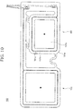
- a first sensor 101 and a second sensor 102 configuring the sheet-shaped sensors 100 of the third embodiment are in a substantially rectangular frame shape as illustrated in the figure, and as a feature thereof, is more downsized as compared to the shape of the sheet-shaped sensor 20.
- a conductive line 101a configuring a sensor body of the first sensor 101 is bonded to the outer surface of a conductive sheet 101b along the substantially rectangular frame shape of the conductive sheet 101b.
- the conductive sheet 101b includes, as a sensor overlap reduction section, a cutout 101c formed by cutting out a substantially-rectangular center portion of the conductive sheet 101b, and a corner 101e provided with R.
- the second sensor 102 and third and fourth sensors are in the same shape as that of the first sensor 101.
- the vehicle seat S is configured such that the sheet-shaped sensor 20 includes, at the outer peripheral portion thereof, the cutouts as the sensor overlap reduction section, but the present invention is not limited to such a configuration.
- the sheet-shaped sensor 20 may be configured such that an opening or a cutout is formed in at least part of the sheet-shaped sensor 20.
- the configuration may be employed, in which the sensor overlap reduction section is provided in the seat back 2 to which the sheet-shaped sensors 20 are attached.
- the configuration may be employed, in which part of the front side of the cushion pad 2a to which the sheet-shaped sensors 20 are attached is partially softened to provide the sensor overlap reduction section.
- the sheet-shaped sensors 20 easily follow elastic deformation of the cushion pad 2a, and therefore, partial overlapping of the sheet-shaped sensor 20 can be reduced.
- the configuration may be employed, in which a groove having a predetermined depth is, as another sensor overlap reduction section, formed in part of a portion of the front side of the cushion pad 2a, the sheet-shaped sensors 20 being attached to such a portion of the front side of the cushion pad 2a.
- the sheet-shaped sensors 20 easily follow elastic deformation of the cushion pad 2a, and therefore, partial overlapping of the sheet-shaped sensor 20 can be reduced.
- the shape of the groove is optionally changeable according to the shape of the sheet-shaped sensor 20, and for example, is a substantially petal-shaped cross-sectional shape, a substantially X-shaped cross-sectional shape, a substantially cross-shaped cross-sectional shape, or a substantially circular cross-sectional shape as viewed from the seat front side.
- the configuration may be employed, in which a well-known deformable absorbing member 2c is, as still another sensor overlap reduction section, disposed between the cushion pad 2a and each sheet-shaped sensor 20 at part of the front side of the cushion pad 2a to which the sheet-shaped sensors 20 are attached.
- a well-known deformable absorbing member 2c is, as still another sensor overlap reduction section, disposed between the cushion pad 2a and each sheet-shaped sensor 20 at part of the front side of the cushion pad 2a to which the sheet-shaped sensors 20 are attached.
- the sheet-shaped sensors 20 easily follow elastic deformation of the cushion pad 2a, and therefore, partial overlapping of the sheet-shaped sensor 20 can be reduced.
- an elastic member made of a cushion material or rubber can be used as the well-known deformable absorbing member 2c, and a material softer than the cushion pad 2a may be used.
- the shape of the deformable absorbing member 2c is optionally changeable according to the shape of the sheet-shaped sensor 20, and for example, is a substantially petal shape, a substantially X-shape, a substantially cross shape, or a substantially circular shape as viewed from the seat front side.
- the ground electrode 10 and the sheet-shaped sensors 20 are each formed of the conductive fabric tape, but the present invention is not limited to such a configuration.
- Such a material is optionally changeable as long as the material is a metal conductor having conductivity. Examples of the material include conductive fibers.
- Each sheet-shaped sensor 20 includes the conductive line configuring the sensor body, and the conductive sheet for protecting the conductive line, but the present invention is not limited to such a configuration.
- the sheet-shaped sensor 20 may be formed only of the conductive sheet without the conductive line.
- gold paste, silver paste, or copper paste having a high conductivity can be used for the conductive line
- carbon paste resistive to oxidation and having conductivity can be used for the conductive sheet.
- the sheet-shaped sensors 20 are arranged between the cushion pad 2a and the skin 2b, but the present invention is not limited to such a configuration.
- the sheet-shaped sensors 20 may be attached to the skin 2b.
- the number of sheet-shaped sensors 20 are four, but the number of sheet-shaped sensors 20 are not limited to four.
- the number of sheet-shaped sensors 20 may be optionally adjustable considering the balance between stability in potential difference detection and a manufacturing cost.
- the second sensor 22 configuring the sheet-shaped sensor 20 has a larger size than that of the first sensor 21, and is disposed to protrude above the first sensor 21.
- the present invention is not limited to such a configuration.
- the first sensor 21 may have a larger size than that of the second sensor 22, and may be disposed to protrude above the second sensor 22.
- the first sensor 21 and the second sensor 22 may have the same size.
- the distribution cable 25 connected to the first sensor 21 may be disposed outside the first sensor 21 in the seat width direction at the seat back 2, and the distribution cable 25 connected to the second sensor 22 may be disposed outside the second sensor 22 in the seat width direction.
- the distribution cables 25 can be compactly arranged.
- the heart rate measurement device 3 includes, as a component, the display D showing the electrocardiographic waveform, but may additionally include a vibration motor for maintaining the seated passenger at an awakening state, a transmitter for generating an alarm, or a light emitter for emitting light.
- the vehicle seat S of the present embodiment can be utilized for the purpose of monitoring a passenger having a heart problem.
- the display D may be disposed in such a position that a passenger(s) other than the passenger having the heart problem can monitor the working condition of the heart.
- a vibration motor may be provided in a seat other than the seat provided with the heart rate measurement device 3. When a decline in the function of the heart is detected, such a seat may vibrate to report to other passenger(s).
- a typical communication section may be used to urgently report to a hospital, a fire department, or a police station.
- the person with a height of 150 cm has been described as an example of the seated passenger assumed as being physically small, and the person with a height of 190 cm has been described as an example of the seated passenger assumed as being physically big.
- such assumption is optional.
- a reference physique may be set according to such assumption. Similar advantageous effects can be provided in the following manner. The positions of a plurality of the sheet-shaped sensors 20 are determined such that in the state in which a passenger with the reference physique is seated and faces forward of the seat back 2, the sheet-shaped sensors 20 sandwich the heart of the passenger.
- the heart rate measurement device 3 which can measure the heart rate (the vital information) of the seated passenger based on the electric signal (the vital signal) associated with the biopotential of the seated passenger has been described as an example of the vital information measurement device.
- the present invention is not limited to the heart rate measurement device 3, and the heart rate measurement device 3 is changeable.
- Examples include a respiration measurement device which includes sheet-shaped piezoelectric sensors configured to detect a change in expansion/contraction of the chest in association with respiration of the seated passenger and which can measure respiration, taken as the vital information of the seated passenger, based on the vital signals detected by the sheet-shaped piezoelectric sensors.
- the examples further include a humidity measurement device which includes sheet-shaped humidity sensors (sheet-shaped capacitance sensors) configured to detect a change in humidity around the seated passenger in association with contact with the seated passenger and which can measure the humidity associated with the vital information of the seated passenger based on the vital signals detected by the sheet-shaped humidity sensors.
- sheet-shaped humidity sensors sheet-shaped capacitance sensors
- the vehicle seat used for automobiles has been described as a specific example, but the present invention is not limited to such a vehicle seat.
- the vehicle seat can be utilized not only as vehicle seats of trains and buses but also as vehicle seats of airplanes and ships.
- the vital information measurement device may be applied not only to the vehicle seats but also to typical seats such as chairs, beds, and sofas. In addition to these seats, the vital information measurement device may be attached to attachment bodies contacting humans or animals, such as blankets, Japanese-style bedding, sheets, mats, and clothes. In this case, a human or an animal may directly contact the sheet-shaped sensors, or may indirectly contact the sheet-shaped sensors via another member.
- the vehicle seat including the vital information measurement device whose detection target is the seated passenger has been described, but is broadly applicable without limitation of the detection target.
- the detection target may be, in addition to the seated passenger, as seated animals, pets such as dogs and cats and may be typical animals such as cows and horses.
- the vital information measurement device In the case of attaching the vital information measurement device to, for example, a blanket or clothes, measurement is not necessarily made with a human or an animal being seated.
- the vehicle seat S of the present invention has been mainly described.
Landscapes
- Health & Medical Sciences (AREA)
- Life Sciences & Earth Sciences (AREA)
- Engineering & Computer Science (AREA)
- General Health & Medical Sciences (AREA)
- Heart & Thoracic Surgery (AREA)
- Veterinary Medicine (AREA)
- Animal Behavior & Ethology (AREA)
- Public Health (AREA)
- Surgery (AREA)
- Physics & Mathematics (AREA)
- Molecular Biology (AREA)
- Biophysics (AREA)
- Pathology (AREA)
- Biomedical Technology (AREA)
- Medical Informatics (AREA)
- Cardiology (AREA)
- Mechanical Engineering (AREA)
- Transportation (AREA)
- Aviation & Aerospace Engineering (AREA)
- Psychology (AREA)
- Child & Adolescent Psychology (AREA)
- Social Psychology (AREA)
- Developmental Disabilities (AREA)
- Psychiatry (AREA)
- Hospice & Palliative Care (AREA)
- Educational Technology (AREA)
- Physiology (AREA)
- Signal Processing (AREA)
- Seats For Vehicles (AREA)
- Measuring Pulse, Heart Rate, Blood Pressure Or Blood Flow (AREA)
- Measurement And Recording Of Electrical Phenomena And Electrical Characteristics Of The Living Body (AREA)
Abstract
Description
- The present invention relates to a vital information measurement device and a vehicle seat, and particularly relates to a vital information measurement device having the function of measuring vital information of a human or an animal and to a vehicle seat.
- Recent years, for the purpose of promptly reporting, to a driver, that a driver's physical condition is changed while a vehicle is running, various vehicle seats configured to be able to display a change in physical condition by detecting various parameters indicating the state of the driver have been proposed.
- For example,
Patent Literature 1 discloses an electrocardiogram measurement device including first and second electrodes serving as two sensors optionally arranged at a seat back and a ground electrode disposed in a seat cushion and configured to determine a reference potential. - In this electrocardiogram measurement device, an electric signal associated with an electrocardiogram detected from a driver by two sensors is efficiently sensed in such a manner that the electric signal is amplified by a two-stage amplifier, and therefore, the health condition of the driver can be determined.
-
Patent Literature 2 discloses a measurement device including planar electrodes serving as a plurality of sensors arranged respectively at the positions contacting the back of a driver, the region extending from the waist to the hip of the driver, and the thighs of the driver. - In this measurement device, one of the sensors is provided for obtaining the neutral-point potential of an amplifier. This reduces signal noise, and therefore, abnormality can be determined in such a manner that a heart-rate signal and a respiration signal from the driver are suitably detected.
-
- Patent Document 1:
JP 2009-50679 A - Patent Document 2:
JP 2007-301175 A - Sheet-shaped sensors are broadly used as the sensors of
Patent Literatures - The sheet-shaped sensor of this type might receive a compressive load when the seated passenger leans on the seat back, resulting in wrinkling caused due to partial overlapping of the sheet-shaped sensor. As a result, there is a possibility that signal noise is caused or that the conductive line deforms due to repeat load application.
- However, in the vehicle seat including the vital information measurement device as described in
Patent Literatures - For this reason, vehicle seats has been demanded, which include sheet-shaped sensors which can stably detect vital signals from seated passengers such as humans or animals and which improves durability against repeat load application.
- The present invention has been made in view of the above-described problem, and is intended to provide a vital information measurement device which improves the durability of sheet-shaped sensors configured to detect vital signals from a human or an animal and which can stably measure vital information of the human or the animal and to provide a vehicle seat.
- In particular, the present invention is intended to provide a vital information measurement device which improves the durability of sheet-shaped sensors configured to detect electric signals associated with the biopotential of a seated passenger and which can stably measure the heart rate of the seated passenger and to provide a vehicle seat.
- According to the vital information measurement device of the present invention, the above-described problem is solved by a vital information measurement device including a sheet-shaped sensor that is configured to detect a vital signal of a human or an animal, wherein the vital information measurement device can measure vital information of the human or the animal based on the vital signal detected by the sheet-shaped sensor, and a sensor overlap reduction section configured to reduce partial overlapping of the sheet-shaped sensor when the human or the animal directly or indirectly contacts the sheet-shaped sensor is provided in at least one of the sheet-shaped sensor or an attachment body to which the sheet-shaped sensor is attached.
- As described above, the sensor overlap reduction section configured to reduce partial overlapping of the sheet-shaped sensor when the human or the animal contacts the sheet-shaped sensor is provided in at least one of the sheet-shaped sensor or the attachment body. Thus, the vital information measurement device can be provided, which improves the durability of the sheet-shaped sensor configured to detect the vital signal of the human or the animal and which can stably measure the vital information of the human or the animal.
- Specifically, even if the sheet-shaped sensor mainly including the conductive line configuring the sensor body and the conductive sheet fixing the conductive line receives the compressive load from the human or the animal, deformation of the conductive line is reduced by the sensor overlap reduction section. As a result, the durability of the sheet-shaped sensor is improved, and occurrence of signal noise is reduced by reduction in overlapping of the sheet-shaped sensor.
- In the above-described state, the sheet-shaped sensor may detect, as the vital signal, an electric signal associated with the biopotential of the human or the animal, and the heart rate (the vital information) of the human or the animal may be measureable based on the electric signal detected by the sheet-shaped sensor.
- With the above-described configuration, the device can be provided, which improves the durability of the sheet-shaped sensor configured to detect the electric signal associated with the biopotential of the human or the animal and which can stably measure the heart rate of the human or the animal.
- In the above-described state, an opening or a cutout may be, as the sensor overlap reduction section, formed in at least part of the sheet-shaped sensor.
- At least one or more of cutouts may be, as the sensor overlap reduction section, formed in an outer peripheral portion of the sheet-shaped sensor.
- With the above-described configuration, when the human or the animal contacts the sheet-shaped sensor, the sheet-shaped sensor easily follows elastic deformation of the sheet-shaped sensor itself and elastic deformation of the attachment body. As a result, the durability of the sheet-shaped sensor against repeat load application is improved.
- In the above-described state, the cutout may include a first cutout extending toward the center of the sheet-shaped sensor at the outer peripheral portion of the sheet-shaped sensor, and a second cutout formed continuously from the first cutout and extending opposite to the center along the outer peripheral portion of the sheet-shaped sensor.
- With the above-described configuration, the sheet-shaped sensor more easily follows elastic deformation of the sheet-shaped sensor itself and elastic deformation of the attachment body. As a result, the durability of the sheet-shaped sensor is further improved.
- In the above-described state, the sheet-shaped sensor may at least include a conductive line configuring a sensor body, and a conductive sheet fixing the conductive line, and the conductive line may be disposed along an outer peripheral portion of the conductive sheet.
- With the above-described configuration, the sensor overlap reduction section provided in the outer peripheral portion of the conductive sheet reduces deformation of the conductive line disposed along the outer peripheral portion. As a result, the durability of the sheet-shaped sensor is improved, and occurrence of signal noise is reduced.
- In the above-described state, the attachment body may be a seat back serving as a backrest of a vehicle seat on which the human or the animal is seated. The sheet-shaped sensor may be disposed in part of the seat back supporting the back of the human or the animal. The sheet-shaped sensor may include a first sensor and a second sensor disposed on the right side of the first sensor as viewed from the seated human or the seated animal.
- The second sensor may be disposed in opposite to the first sensor in the vertical direction, and protrudes above the first sensor.
- With the above-described configuration, when the seated human or the seated animal leans on the seat back, the sheet-shaped sensor easily follows elastic deformation of the cushion pad configuring the seat back. As a result, the durability of the sheet-shaped sensor against repeat load application is improved.
- Moreover, with the above-described configuration, the sheet-shaped sensor easily and stably detects a great potential difference signal generated in association with contraction of a heart of the seated human or the seated animal.
- Specifically, a heart-induced electric vector produced when the heart of a person expands/contracts typically points in the direction substantially from the right shoulder to the left leg. Such a direction corresponds to the direction from the upper right side to the lower left side as viewed from the seated passenger. In this state, since the second sensor disposed on the right side as viewed from the seated passenger protrudes above the first sensor, these sensors are in such arrangement that the direction connecting between the second sensor and the first sensor is along the direction of the heart-induced electric vector. Thus, the sheet-shaped sensor easily and stably detects the potential difference signal generated in associated with contraction of the heart. Moreover, since the vital information can be measured at, for example, a position near the heart, the heart rate information is easily measured.
- In the above-described state, the vital information measurement device may include a distribution cable electrically connected to the sheet-shaped sensor and configured to transmit the electric signal detected by the sheet-shaped sensor, and the distribution cable may be disposed outside the first and second sensors in a seat width direction at the seat back.
- With the above-described configuration, the distribution cable can be compactly gathered, and therefore, the size of the seat back configuring the vehicle seat can be reduced.
- In the above-described state, the distribution cable may be disposed outside the first sensor in the seat width direction at the seat back, and part of the second sensor protruding above the first sensor may extend in the seat width direction, and is electrically connected to the distribution cable.
- With the above-described configuration, each of the first and second sensors can be, using a free space, electrically connected to the distribution cable, and the size of the seat back can be reduced.
- In the above-described state, the sheet-shaped sensor may include a sensor connection portion connecting the first and second sensors together.
- With the above-described configuration, since the first and second sensors form an integrated component, the sheet-shaped sensor is, with high accuracy, easily attached to a pre-set position of the seat back. Moreover, the number of components can be reduced.
- In the above-described state, the sheet-shaped sensor may further include a third sensor disposed above the first and second sensors, and a fourth sensor disposed on the right side of the third sensor as viewed from the seated human or the seated animal. The fourth sensor may be disposed in opposite to the third sensor in the vertical direction, and may protrude above the third sensor.
- With the above-described configuration, the sheet-shaped sensor can stably detect the vital signal regardless of a physique difference among seated passengers.
- Specifically, the sheet-shaped sensor is disposed such that the position of the heart of a small seated passenger is within the region surrounded by the first and second sensors, and is disposed such that the position of the heart of a big seated passenger is within the region surrounded by the third and fourth sensors.
- Moreover, according to the vehicle seat of the present invention, the above-described problem is solved in such a manner that the vehicle seat includes the above-described vital information measurement device.
- In such a state, the sheet-shaped sensor may be attached to a cushion pad configuring the seat back, and a cable housing recess may be formed in part of the cushion pad in opposite to the distribution cable.
- With the above-described configuration, the distribution cable can be compactly housed, and therefore, the size of the seat back can be reduced. Moreover, the sense of discomfort is reduced when the seated passenger leans on the seat back.
- In the above-described state, the seat back may be configured such that the cushion pad is covered with a skin, a skin insertion groove into which an end of the skin is inserted may be formed in the cushion pad, and the sheet-shaped sensor may be disposed in a position other than part of the cushion pad formed with the skin insertion groove.
- Moreover, the sheet-shaped sensor may be disposed along the skin insertion groove.
- With the above-described configuration, when the cushion pad to which the sheet-shaped sensor is attached is covered with the skin, the sheet-shaped sensor and the skin insertion groove do not interfere with each other. Thus, the end of the skin can be efficiently inserted into the skin insertion groove.
- According to the present invention, the sensor overlap reduction section is provided. Thus, the vital information measurement device can be provided, which improves the durability of the sheet-shaped sensor configured to detect the vital signal of the human or the animal and which can stably measure the vital information of the human or the animal.
- According to the present invention, when the human or the animal contacts the sheet-shaped sensor, the sheet-shaped sensor easily follows elastic deformation of the sheet-shaped sensor itself and elastic deformation of the attachment body. As a result, the durability of the sheet-shaped sensor against repeat load application is improved.
- According to the present invention, when the seated human or the seated animal leans on the seat back, the sheet-shaped sensor easily follows elastic deformation of the cushion pad configuring the seat back. As a result, the durability of the sheet-shaped sensor against repeat load application is improved.
- Moreover, the sheet-shaped sensor easily and stably detects a great potential difference signal generated in association with contraction of the heart of the seated human or the seated animal.
- According to the present invention, the distribution cable can be compactly gathered, and therefore, the size of the seat back configuring the vehicle seat can be reduced.
- According to the present invention, since the first and second sensors form an integrated component, the sheet-shaped sensor is, with high accuracy, easily attached to the pre-set position of the seat back. Moreover, the number of components can be reduced.
- According to the present invention, the sheet-shaped sensor can stably detect the vital signal regardless of the physique difference among seated passengers.
- According to the present invention, the size of the seat back can be reduced. Moreover, the sense of discomfort is reduced when the seated passenger leans on the seat back.
- According to the present invention, the end of the skin can be efficiently inserted into the skin insertion groove.
-
-
FIG. 1 is a view illustrating the entire configuration of a vehicle seat of the present invention. -
FIG. 2 is a partial longitudinal sectional view of a seat back illustrating arrangement of sheet-shaped sensors. -
FIG. 3 is a front view of a cushion pad illustrating arrangement of the sheet-shaped sensors. -
FIG. 4 is a front view illustrating the shape of the sheet-shaped sensors. -
FIG. 5 is a view illustrating the difference in the height of the heart due to a physique difference. -
FIG. 6 is a schematic diagram illustrating a circuit configuration and an arithmetic device configuration which are provided for electrocardiographic signal detection. -
FIGS. 7(a) and 7(b) are graphs showing examples of detected waveform data. -
FIG. 8 is a flowchart showing an example of a heart rate measurement process. -
FIG. 9 is a front view illustrating a second embodiment of the sheet-shaped sensor. -
FIG. 10 is a front view illustrating a third embodiment of the sheet-shaped sensor. -
FIG. 11 is a partial longitudinal sectional view of a seat back illustrating arrangement of a deformable absorbing member. - The present embodiment relates to a vehicle seat which includes sheet-shaped sensors attached to a seat back and which can measure the heart rate of a seated passenger based on vital signals of the seated passenger detected by the sheet-shaped sensors. Each sheet-shaped sensor includes, as a sensor overlap reduction section, a plurality of cutouts at an outer peripheral portion thereof.
- Note that the side on which the passenger is seated on the seat back of the vehicle seat is a seat front side.
- A vehicle seat S of the present embodiment mainly includes, as illustrated in
FIG. 1 , aseat cushion 1 on which a passenger is seated, a seat back 2 rotatably attached to a back portion of theseat cushion 1 and serving as a backrest of the seated passenger, and a heartrate measurement device 3 including a plurality of sheet-shapedsensors 20 attached inside the seat back 2. - Note that in the embodiments, the seat back 2 is equivalent to an attachment body, and the heart
rate measurement device 3 is equivalent to a vital information measurement device. - As illustrated in
FIG. 1 , theseat cushion 1 is configured such that acushion pad 1a placed on a not-shown cushion frame configuring a framework is covered with askin 1b. - A
ground electrode 10 is disposed between thecushion pad 1a and theskin 1b at the position facing the hip of the seated passenger. - As illustrated in
FIG. 1 , the seat back 2 is configured such that acushion pad 2a placed on a not-shown back frame configuring the framework is covered with askin 2b. - Moreover, as illustrated in
FIG. 2 , the sheet-shapedsensors 20 are arranged between thecushion pad 2a and theskin 2b at part of the seat back 2 supporting the back of the seated passenger. - Note that a not-shown cushion slab may be further disposed between the
cushion pad 2a and each sheet-shapedsensor 20. This configuration reduces the influence on measurement accuracy and the sense of discomfort when the seated passenger leans on the seat back 2. - The heart
rate measurement device 3 is a device configured to detect an electric signal associated with the biopotential of the seated passenger to measure the heart rate of the seated passenger based on the detected electric signal. The heartrate measurement device 3 mainly includes, as illustrated inFIG. 1 , theground electrode 10 provided inside theseat cushion 1, the sheet-shapedsensors 20 provided inside the seat back 2, aninstrumentation amplifier 30, a DCcomponent removal circuit 40, an invertingamplifier 50, apassband filter 60, an A/D converter circuit 70, anarithmetic device 80, and a display D. - The
ground electrode 10 is formed of a conductive fabric tape, and is configured to obtain a reference potential when an offset signal contained in the electric signal detected by the sheet-shapedsensor 20 is removed. Theground electrode 10 is disposed in part of theseat cushion 1 facing the hip of the seated passenger. - The
ground electrode 10 has a function to be capacitance-coupled to the body of the seated passenger via theskin 1b and cloths to detect the electric signal associated with the biopotential of the seated passenger. - Each sheet-shaped
sensor 20 is formed of a conductive fabric tape, the conductive fabric tape including a conductive line configuring a sensor body and a conductive sheet for bonding the conductive line. As illustrated inFIG. 2 , each sheet-shapedsensor 20 is a sensor configured to be capacitance-coupled to the body of the seated passenger via theskin 2b and the cloths to detect the electric signal associated with the biopotential of the seated passenger. - As illustrated in
FIG. 3 , each sheet-shapedsensor 20 is bonded to the front side of thecushion pad 2a configuring the seat back 2. The sheet-shapedsensors 20 include afirst sensor 21 and asecond sensor 22 arranged at the substantially middle of thecushion pad 2a in a seat width direction, and athird sensor 23 and afourth sensor 24 arranged above thefirst sensor 21 and thesecond sensor 22. - The
first sensor 21 is in a substantially petal shape, and is disposed in opposite to thesecond sensor 22 in the vertical direction. Thefirst sensor 21 may have an optional size, and for example, the relationship between the height and the width may be a ratio of about 3:4. - As illustrated in
FIG. 4 , aconductive line 21 a configuring the sensor body of thefirst sensor 21 is formed along an outer peripheral portion (an outer edge portion) of aconductive sheet 21 b and along the diagonal lines of theconductive sheet 21b, and is bonded to the outer surface of theconductive sheet 21 b. - The
conductive sheet 21b includes, as a sensor overlap reduction section, fourfirst cutouts 21c extending toward the center at the outer peripheral portion of theconductive sheet 21b, and threesecond cutouts 21d each formed continuously from a corresponding one of thefirst cutouts 21 c and extending opposite to the center along the outer peripheral portion of theconductive sheet 21 b. - Each
first cutout 21c is a cutout in a substantially semi-elliptical shape, and is formed from a corresponding one of the four sides of theconductive sheet 21b toward the center at the outer peripheral portion of theconductive sheet 21b. - Each
second cutout 21d is a cutout in a substantially triangular shape. Eachsecond cutout 21d is formed continuously from a corresponding one of threefirst cutouts 21c other than thefirst cutout 21c formed in an upper portion of theconductive sheet 21b, and is formed along the outer peripheral portion of theconductive sheet 21b such that the width thereof increases with an increase in the distance from the center. - Specifically, each
second cutout 21d extends continuously from a corresponding one of thefirst cutouts 21c such that the width thereof increases toward ones ofcorners 21e positioned respectively on opposing sides relative to the corresponding one of thefirst cutouts 21c, supposing that four corners of the outer peripheral portion of theconductive sheet 21 b positioned farthest from the center are thecorners 21e. - An optional level of R is provided to the
corners 21e and to each corner portion where thefirst cutout 21c and thesecond cutout 21 d are continuous from each other, and therefore, partial overlapping of thefirst sensor 21 when the seated passenger leans on the seat back 2 can be reduced. - Note that the total depth of the
first cutout 21c and thesecond cutout 21d may be optionally set, and for example, is preferably set at equal to or less than about 1/4 of the width of thefirst sensor 21 in the seat width direction. - As illustrated in
FIG. 3 or4 , thesecond sensor 22 is in a substantially petal shape. Thesecond sensor 22 is disposed on the right side of thefirst sensor 21 as viewed from the seated passenger, and protrudes above thefirst sensor 21. Thesecond sensor 22 may have an optional size, and for example, the relationship between the height and the width may be a ratio of about 1:1. - As in the
first sensor 21, aconductive line 22a configuring the sensor body of thesecond sensor 22 is formed along an outer peripheral portion of aconductive sheet 22b and along the diagonal lines of theconductive sheet 22b, and is bonded to the outer surface of theconductive sheet 22b. - The
conductive sheet 22b includes, as a sensor overlap reduction section, fourfirst cutouts 22c extending toward the center at the outer peripheral portion of theconductive sheet 22b, and foursecond cutouts 22d each formed continuously from a corresponding one of thefirst cutouts 22c and extending opposite to the center along the outer peripheral portion of theconductive sheet 22b. - Note that the
second cutouts 22d are different from thesecond cutouts 21d of thefirst sensor 21 in that eachsecond cutout 22d is formed continuously from a corresponding one of all of fourfirst cutouts 22c. - Moreover, the total depth of the
first cutout 22c and thesecond cutout 22d may be optionally set, and for example, is preferably set at equal to or less than about 1/4 of each of the height and width of thesecond sensor 22 in each of the vertical direction and the seat width direction. - As illustrated in
FIG. 3 , thefirst sensor 21 and thesecond sensor 22 are arranged respectively on opposing sides relative to the center line of the seat back 2 in the seat width direction. - The
first sensor 21 and thesecond sensor 22 are electrically connected respectively todistribution cables 25 disposed outside thefirst sensor 21 in the seat width direction at the seat back 2. - The
distribution cables 25 are cables for transmitting, to theinstrumentation amplifier 30, electric vital signals detected by the sheet-shapedsensors 20. As illustrated inFIG. 4 , oneend 25a of thedistribution cable 25 is connected to theconductive line 21a of thefirst sensor 21 at a lower end portion of thefirst sensor 21 positioned opposite to thesecond sensor 22. - Moreover, the
other end 25b of thedistribution cable 25 is connected to theconductive line 22a of thesecond sensor 22 at part of thesecond sensor 22 protruding above thefirst sensor 21 and positioned close to thefirst sensor 21. - Specifically, the upwardly-protruding portion of the
second sensor 22 positioned close to thefirst sensor 21 forms asecond sensor extension 26 extending horizontally in the seat width direction, and an end portion of thesecond sensor extension 26 is connected to theend 25b of thedistribution cable 25. - The
second sensor extension 26 is in a rectangular shape elongated in the seat width direction, and is disposed to extend over thefirst sensor 21. - The
first sensor 21 and thesecond sensor 22 are connected together via threesensor connection portions 27 to form an integrated component. - Each
sensor connection portion 27 is made of a sheet material in a substantially curved shape. One of thesensor connection portions 27 is disposed to connect between a lower end portion of thefirst sensor 21 positioned close to thesecond sensor 22 and a lower end portion of thesecond sensor 22 positioned close to thefirst sensor 21. - The remaining two
sensor connection portions 27 connect between an upper end portion of thefirst sensor 21 and thesecond sensor extension 26 of thesecond sensor 22, and are arranged with a predetermined distance in the seat width direction. - As described above, since the
sensor connection portions 27 are in the curved shape, the entirety of the sheet-shapedsensors 20 including thesensor connection portions 27 easily follows elastic deformation of thecushion pad 2a, and therefore, durability is improved. - The shape, arrangement, and configuration of the
third sensor 23 and thefourth sensor 24 are the same as those of thefirst sensor 21 and thesecond sensor 22. As illustrated inFIG. 3 , thethird sensor 23 and thefourth sensor 24 are electrically connected respectively todistribution cables 25 disposed outside thethird sensor 23 in the seat width direction at the seat back 2. - As illustrated in
FIG. 3 , acable housing recess 28 is formed in a front portion of thecushion pad 2a of the seat back 2 in opposite to thedistribution cables 25, and askin insertion groove 29 is formed in part of thecushion pad 2a other than part of thecushion pad 2a to which the sheet-shapedsensors 20 are attached. - The
cable housing recess 28 is a housing groove elongated in the vertical direction and having a substantially rectangular cross section, and is formed to have a size sufficient for housing thedistribution cables 25. - Note that a not-shown through-hole is formed to penetrate, in a seat front-to-back direction, part of the
cushion pad 2a positioned above the sheet-shapedsensors 20, and thedistribution cables 25 extend from the front side of thecushion pad 2a to pass through the through-hole, and then, are connected to theinstrumentation amplifier 30 disposed on the back side of thecushion pad 2a. - The
skin insertion groove 29 is a groove into which an end of theskin 2b is inserted. Theskin insertion groove 29 includes two grooves elongated in the vertical direction and having a substantially rectangular cross section, and two grooves elongated in the seat width direction and having a substantially rectangular cross section. Theskin insertion groove 29 is at a position other than the position of the entirety of the sensor bodies of the sheet-shapedsensors 20. - Such arrangement prevents the sheet-shaped
sensors 20 and theskin insertion groove 29 from interfering with each other in the process of inserting the skin end. - A
skin insertion groove 29a elongated in the seat width direction is formed in part of thecushion pad 2a having the greatest thickness in the seat front-to-back direction. The sheet-shapedsensors 20 are arranged to surround and sandwich theskin insertion groove 29a. - Such arrangement of the sheet-shaped
sensors 20 easily determine the positions of the sheet-shapedsensors 20, resulting in better assembly. - The height positions of the sheet-shaped
sensors 20 attached to thecushion pad 2a will be described with reference toFIGS. 3 and5 . - First, a physically-small female and a physically-big male are illustrated in
FIG. 5 as examples of seated passengers with a physique difference. Suppose that the female assumed as being physically small has a height of about 150 cm, and the male assumed as being physically big has a height of about 190 cm. - When seated on the
seat cushion 1, the heart of the female is at a height HF from a cushion seating surface corresponding to the upper surface of theseat cushion 1, and the heart of the male is at a height HM from the cushion seating surface. - For the sheet-shaped
sensors 20 attached to the seat back 2, arrangement in a height direction is set depending on a heart position difference caused due to the physique difference. - Specifically, as illustrated in
FIG. 3 , thefirst sensor 21 and thesecond sensor 22 are arranged such that the height of the center between thefirst sensor 21 and thesecond sensor 22 from the cushion seating surface corresponds to the height HF of the heart of the female. Moreover, thethird sensor 23 and thefourth sensor 24 are arranged such that the height of the center between thethird sensor 23 and thefourth sensor 24 from the cushion seating surface corresponds to the height HM of the heart of the male. - Of the sheet-shaped
sensors 20 arranged as described above, the leftfirst sensor 21 and the rightsecond sensor 22 as viewed from the seated passenger are arranged to sandwich the heart of the female in an oblique direction. The region defined to include thefirst sensor 21 at a lower left corner and to include thesecond sensor 22 at an upper right corner is a region where a suitable potential difference is obtained in detection of the cardiac potential of the female. - Similarly, the left
third sensor 23 and the rightfourth sensor 24 as viewed from the seated passenger are arranged to sandwich the heart of the male in the oblique direction. The region defined to include thethird sensor 23 at a lower left corner and to include thefourth sensor 24 at an upper right corner is a region where a suitable potential difference is obtained in detection of the cardiac potential of the male. - Reasons for such arrangement will be described below. Typically, the heart-induced electric vector produced in expansion/contraction of the heart of a person points in the direction substantially from the right shoulder to the left leg. Such a direction corresponds to the direction from the upper right side to the lower left side as viewed from the seated passenger when the passenger is seated on the vehicle seat S. In this state, since the second sensor disposed on the right side as viewed from the seated passenger protrudes above the first sensor, these sensors are in such arrangement that the direction connecting between the second sensor and the first sensor is along the direction of the heart-induced electric vector. Thus, the sheet-shaped sensors easily and stably detect great potential difference signals generated in associated with contraction of the heart.
- Next, the
instrumentation amplifier 30 includes, as illustrated inFIG. 6 ,operational amplifiers operational amplifiers sensors 20 to output the signals to theoperational amplifier 33. - The
operational amplifier 33 is a differential amplifier, and is configured to amplify a difference signal of the electric signals output from theoperational amplifiers - The potential of the
ground electrode 10 is, as a reference potential, applied to a positive input terminal of theoperational amplifier 33. Theground electrode 10 is provided in theseat cushion 1 farther from the heart of the seated passenger than the sheet-shapedsensors 20 provided in the seat back 2, and is capacitance-coupled to the hip of the seated passenger. Thus, the potential less susceptible to the influence of an electrocardiographic signal is obtained from theground electrode 10. - A
capacitor 41 serving as the DCcomponent removal circuit 40 has a function to remove a low-frequency component, including a direct-current component, of the potential difference signal output from theoperational amplifier 33, and AC-couples an output terminal of theoperational amplifier 33 and a negative input terminal of the invertingamplifier 50 together. - The inverting
amplifier 50 has a function to invert, for further amplification, the polarity of the potential difference signal from which the direct-current component is removed. The negative input terminal of the invertingamplifier 50 is connected to thecapacitor 41 via a resistor, and the potential of theground electrode 10 is applied to a positive input terminal of the invertingamplifier 50 as a reference potential. - The
passband filter 60 is provided to remove, from the potential difference signal output from the invertingamplifier 50, a low-frequency component and a high-frequency component, these components being not taken as the frequency of the electrocardiographic signal. - The
passband filter 60 inputs, in a restrictive manner, the potential difference signal having the frequency of the electrocardiographic signal to the A/D converter circuit 70. - The A/
D converter circuit 70 is configured to convert, as an input signal of thearithmetic device 80, an analog signal input from the invertingamplifier 50 via thepassband filter 60 into a digital signal. - The
arithmetic device 80 includes, for arithmetic control, aCPU 81, aRAM 82, and aROM 83. - The signal input to the
arithmetic device 80 is the potential difference signal converted into the digital signal, and the signal output from thearithmetic device 80 is the electric signal to be displayed on the display D. - The
RAM 82 is configured to temporarily store the parameters containing the signal during the arithmetic control and the input and output signals, and has a function as astorage 82a configured to store the potential difference signal converted into the digital signal and other signals. - The
ROM 83 is configured to store the program to be executed by theCPU 81 and parameters of predetermined values. TheROM 83 stores, as programs, awaveform generator 83a configured to generate voltage waveform data from the potential difference signal obtained from the sheet-shapedsensors 20 and aselector 83b configured to select voltage waveform data periodically oscillating in association with contraction of the heart. - The
waveform generator 83a has a function to generate voltage waveform data V1 based on the potential difference signal, stored in thestorage 82a, between thefirst sensor 21 and thesecond sensor 22 and a function to generate voltage waveform data V2 based on the potential difference signal between thethird sensor 23 and thefourth sensor 24, provided that the vertical axis represents the potential difference signal and the horizontal axis represents the time. - The
selector 83b has a function to select, from the voltage waveform data V1, V2, the voltage waveform data associated with contraction of the heart to set such data as electrocardiographic waveform data VH. - Suppose that the voltage waveform data V1 shown in
FIG. 7(a) is generated based on the potential difference signal between thefirst sensor 21 and thesecond sensor 22 and that the voltage waveform data V2 shown inFIG. 7(b) is generated based on the potential difference signal between thethird sensor 23 and thefourth sensor 24. - In this case, the
selector 83b selects the voltage waveform data V1 clearly showing a periodic R-wave and having a high amplitude to set the voltage waveform data V1 as the electrocardiographic waveform data VH. - Next, a heart rate measurement method by the heart
rate measurement device 3 will be described with reference toFIG. 8 . - In response to start of an engine of the vehicle or pressing of a start switch, the sheet-shaped
sensors 20 detect electric signals associated with the biopotential of the body of the seated passenger. - The electric signals detected by the
first sensor 21 and thesecond sensor 22 are, as potential difference data, stored in thestorage 82a of thearithmetic device 80 via theinstrumentation amplifier 30, the DCcomponent removal circuit 40, the invertingamplifier 50, thepassband filter 60, and the A/D converter circuit 70. Similarly, the electric signals detected by thethird sensor 23 and thefourth sensor 24 are also stored as potential difference data. - That is, the
arithmetic device 80 obtains the potential difference data between thefirst sensor 21 and thesecond sensor 22 and the potential difference data between thethird sensor 23 and the fourth sensor 24 (step S01). - Next, based on the obtained potential difference data between the
first sensor 21 and thesecond sensor 22, thewaveform generator 83a generates the voltage waveform data V1 plotted using the potential difference and the time as axes. Similarly, based on the potential difference data between thethird sensor 23 and thefourth sensor 24, the voltage waveform data V2 is generated (step S02). - Next, the
selector 83b selects, from two pieces of voltage waveform data V1, V2, the data synchronized with the heart rate and having a high R-wave amplitude, thereby setting the selected data as the electrocardiographic waveform data VH (step S03). - Next, the
arithmetic device 80 digitally filters the electrocardiographic waveform data VH to emphasize the waveform associated with a QRS-wave, and then, computes a peak interval at which the voltage (an R-wave potential) exceeding a set threshold is detected. Next, thearithmetic device 80 further calculates the number of detection per minute, the inverse of the peak interval being taken as an instantaneous heart rate (the number of heart beat per second). That is, thearithmetic device 80 calculates the heart rate by computing. Next, thearithmetic device 80 transmits the signals associated with the electrocardiographic waveform data VH and the heart rate to the display D, and then, the electrocardiographic waveform data VH and the heart rate are displayed on the display D (step S04). - Next, the
arithmetic device 80 determines the presence or absence of the instruction of terminating heart rate measurement by a stop switch, and the like (step S05). With the instruction of terminating the heart rate measurement, the process is terminated. Without the instruction, steps S01 to S05 are repeated. - Next, a sheet-shaped
sensor 90 of a second embodiment will be described with reference toFIG. 9 . Note that for the sake of clear explanation of feature differences, the contents overlapping with the sheet-shapedsensor 20 of the above-described embodiment will not be described below. - A
first sensor 91 and asecond sensor 92 configuring the sheet-shapedsensors 90 of the second embodiment are in a substantially X-shape, and as a feature thereof, are more downsized as compared to the shape of the sheet-shapedsensor 20. - A
conductive line 91a configuring a sensor body of thefirst sensor 91 is bonded to the outer surface of aconductive sheet 91 b along the substantially X-shape of theconductive sheet 91 b. - The
conductive sheet 91b includes, as a sensor overlap reduction section, fourcutouts 91 c formed in an outer peripheral portion of theconductive sheet 91b and extending opposite to the center along the outer peripheral portion. - Each
cutout 91c is a substantially triangular cutout, and along the outer peripheral portion of theconductive sheet 91b, is formed wider with an increase in the distance from the center of theconductive sheet 91 b. - Specifically, each
cutout 91c extends from the center along the outer peripheral portion such that the width thereof increases toward ones ofcorners 91e positioned respectively on opposing sides relative to the center, supposing that four corners of the outer peripheral portion of theconductive sheet 91b positioned farthest from the center are thecorners 91 e. R is provided to eachcorner 91 e. - The
second sensor 92 and third and fourth sensors are in the same shape as that of thefirst sensor 91. - Next, a sheet-shaped
sensor 100 of a third embodiment will be described with reference toFIG. 10 . - A
first sensor 101 and asecond sensor 102 configuring the sheet-shapedsensors 100 of the third embodiment are in a substantially rectangular frame shape as illustrated in the figure, and as a feature thereof, is more downsized as compared to the shape of the sheet-shapedsensor 20. - A
conductive line 101a configuring a sensor body of thefirst sensor 101 is bonded to the outer surface of aconductive sheet 101b along the substantially rectangular frame shape of theconductive sheet 101b. - The
conductive sheet 101b includes, as a sensor overlap reduction section, acutout 101c formed by cutting out a substantially-rectangular center portion of theconductive sheet 101b, and acorner 101e provided with R. - The
second sensor 102 and third and fourth sensors are in the same shape as that of thefirst sensor 101. - In the above-described embodiments, the vehicle seat S is configured such that the sheet-shaped
sensor 20 includes, at the outer peripheral portion thereof, the cutouts as the sensor overlap reduction section, but the present invention is not limited to such a configuration. The sheet-shapedsensor 20 may be configured such that an opening or a cutout is formed in at least part of the sheet-shapedsensor 20. - The configuration may be employed, in which the sensor overlap reduction section is provided in the seat back 2 to which the sheet-shaped
sensors 20 are attached. - Specifically, the configuration may be employed, in which part of the front side of the
cushion pad 2a to which the sheet-shapedsensors 20 are attached is partially softened to provide the sensor overlap reduction section. - With such a configuration, when the seated passenger leans on the seat back 2, the sheet-shaped
sensors 20 easily follow elastic deformation of thecushion pad 2a, and therefore, partial overlapping of the sheet-shapedsensor 20 can be reduced. - The configuration may be employed, in which a groove having a predetermined depth is, as another sensor overlap reduction section, formed in part of a portion of the front side of the
cushion pad 2a, the sheet-shapedsensors 20 being attached to such a portion of the front side of thecushion pad 2a. - With such a configuration, when the seated passenger leans on the seat back 2, the sheet-shaped
sensors 20 easily follow elastic deformation of thecushion pad 2a, and therefore, partial overlapping of the sheet-shapedsensor 20 can be reduced. - Note that the shape of the groove is optionally changeable according to the shape of the sheet-shaped
sensor 20, and for example, is a substantially petal-shaped cross-sectional shape, a substantially X-shaped cross-sectional shape, a substantially cross-shaped cross-sectional shape, or a substantially circular cross-sectional shape as viewed from the seat front side. - The configuration may be employed, in which a well-known
deformable absorbing member 2c is, as still another sensor overlap reduction section, disposed between thecushion pad 2a and each sheet-shapedsensor 20 at part of the front side of thecushion pad 2a to which the sheet-shapedsensors 20 are attached. - With such a configuration, when the seated passenger leans on the seat back 2, the sheet-shaped
sensors 20 easily follow elastic deformation of thecushion pad 2a, and therefore, partial overlapping of the sheet-shapedsensor 20 can be reduced. - Note that, for example, an elastic member made of a cushion material or rubber can be used as the well-known
deformable absorbing member 2c, and a material softer than thecushion pad 2a may be used. The shape of thedeformable absorbing member 2c is optionally changeable according to the shape of the sheet-shapedsensor 20, and for example, is a substantially petal shape, a substantially X-shape, a substantially cross shape, or a substantially circular shape as viewed from the seat front side. - In the above-described embodiments, it has been described that the
ground electrode 10 and the sheet-shapedsensors 20 are each formed of the conductive fabric tape, but the present invention is not limited to such a configuration. Such a material is optionally changeable as long as the material is a metal conductor having conductivity. Examples of the material include conductive fibers. - Each sheet-shaped
sensor 20 includes the conductive line configuring the sensor body, and the conductive sheet for protecting the conductive line, but the present invention is not limited to such a configuration. The sheet-shapedsensor 20 may be formed only of the conductive sheet without the conductive line. - Note that, for example, gold paste, silver paste, or copper paste having a high conductivity can be used for the conductive line, and, for example, carbon paste resistive to oxidation and having conductivity can be used for the conductive sheet.
- In the above-described embodiments, the sheet-shaped
sensors 20 are arranged between thecushion pad 2a and theskin 2b, but the present invention is not limited to such a configuration. For example, the sheet-shapedsensors 20 may be attached to theskin 2b. - In the above-described embodiments, the number of sheet-shaped
sensors 20 are four, but the number of sheet-shapedsensors 20 are not limited to four. The number of sheet-shapedsensors 20 may be optionally adjustable considering the balance between stability in potential difference detection and a manufacturing cost. - The
second sensor 22 configuring the sheet-shapedsensor 20 has a larger size than that of thefirst sensor 21, and is disposed to protrude above thefirst sensor 21. However, the present invention is not limited to such a configuration. Conversely, thefirst sensor 21 may have a larger size than that of thesecond sensor 22, and may be disposed to protrude above thesecond sensor 22. Alternatively, thefirst sensor 21 and thesecond sensor 22 may have the same size. - Note that in the case where the
first sensor 21 and thesecond sensor 22 are set to have the same size, thedistribution cable 25 connected to thefirst sensor 21 may be disposed outside thefirst sensor 21 in the seat width direction at the seat back 2, and thedistribution cable 25 connected to thesecond sensor 22 may be disposed outside thesecond sensor 22 in the seat width direction. Thus, thedistribution cables 25 can be compactly arranged. - In the above-described embodiments, the heart
rate measurement device 3 includes, as a component, the display D showing the electrocardiographic waveform, but may additionally include a vibration motor for maintaining the seated passenger at an awakening state, a transmitter for generating an alarm, or a light emitter for emitting light. - Further, the vehicle seat S of the present embodiment can be utilized for the purpose of monitoring a passenger having a heart problem. In this case, the display D may be disposed in such a position that a passenger(s) other than the passenger having the heart problem can monitor the working condition of the heart. In addition, a vibration motor may be provided in a seat other than the seat provided with the heart
rate measurement device 3. When a decline in the function of the heart is detected, such a seat may vibrate to report to other passenger(s). Further, a typical communication section may be used to urgently report to a hospital, a fire department, or a police station. - In the above-described embodiments, the person with a height of 150 cm has been described as an example of the seated passenger assumed as being physically small, and the person with a height of 190 cm has been described as an example of the seated passenger assumed as being physically big. However, such assumption is optional. For example, in the case of assuming only seating of an adult American or assuming only seating of a child, a reference physique may be set according to such assumption. Similar advantageous effects can be provided in the following manner. The positions of a plurality of the sheet-shaped
sensors 20 are determined such that in the state in which a passenger with the reference physique is seated and faces forward of the seat back 2, the sheet-shapedsensors 20 sandwich the heart of the passenger. - In the above-described embodiments, the heart
rate measurement device 3 which can measure the heart rate (the vital information) of the seated passenger based on the electric signal (the vital signal) associated with the biopotential of the seated passenger has been described as an example of the vital information measurement device. However, the present invention is not limited to the heartrate measurement device 3, and the heartrate measurement device 3 is changeable. - Examples include a respiration measurement device which includes sheet-shaped piezoelectric sensors configured to detect a change in expansion/contraction of the chest in association with respiration of the seated passenger and which can measure respiration, taken as the vital information of the seated passenger, based on the vital signals detected by the sheet-shaped piezoelectric sensors.
- The examples further include a humidity measurement device which includes sheet-shaped humidity sensors (sheet-shaped capacitance sensors) configured to detect a change in humidity around the seated passenger in association with contact with the seated passenger and which can measure the humidity associated with the vital information of the seated passenger based on the vital signals detected by the sheet-shaped humidity sensors.
- In the above-described embodiments, the vehicle seat used for automobiles has been described as a specific example, but the present invention is not limited to such a vehicle seat. The vehicle seat can be utilized not only as vehicle seats of trains and buses but also as vehicle seats of airplanes and ships.
- The vital information measurement device may be applied not only to the vehicle seats but also to typical seats such as chairs, beds, and sofas. In addition to these seats, the vital information measurement device may be attached to attachment bodies contacting humans or animals, such as blankets, Japanese-style bedding, sheets, mats, and clothes. In this case, a human or an animal may directly contact the sheet-shaped sensors, or may indirectly contact the sheet-shaped sensors via another member.
- In the above-described embodiments, the vehicle seat including the vital information measurement device whose detection target is the seated passenger has been described, but is broadly applicable without limitation of the detection target.
- For example, the detection target may be, in addition to the seated passenger, as seated animals, pets such as dogs and cats and may be typical animals such as cows and horses.
- In the case of attaching the vital information measurement device to, for example, a blanket or clothes, measurement is not necessarily made with a human or an animal being seated.
- In the present embodiments, the vehicle seat S of the present invention has been mainly described.
- Note that the above-described embodiments have been set forth merely as examples for the sake of easy understanding of the present invention, and are not intended to limit the present invention. Changes and modifications can be made to the present invention without departing from the idea of the present invention, and needless to say, the present invention includes equivalents thereof.
- In particular, the shape, arrangement, configuration of the sheet-shaped
sensors 20 attached to thecushion pad 2a configuring the seat back 2 have been described merely as examples in the above-described embodiments, and are not intended to limit the present invention. -
- S:
- vehicle seat
- 1:
-
seat cushion cushion pad - 2:
- seat back (attachment body) 2c: deformable absorbing member
- 3:
- heart rate measurement device (vital information measurement device)
- 10:
- ground electrode
- 20, 90, 100:
- sheet-shaped sensor
- 21, 91, 101:
- first sensor
- 21a, 22a, 91a, 101a: conductive line
- 21b, 22b, 91b, 101b: conductive sheet
- 21c, 22c: first cutout
- 21d, 22d: second cutout
- 21e, 91e, 101e: corner
- 22, 92, 102:
- second sensor
- 23:
- third sensor
- 24:
- fourth sensor
- 25:
-
distribution cable - 26:
- second sensor extension
- 27:
- sensor connection portion
- 28:
- cable housing recess
- 29:
-
skin insertion groove 29a: skin insertion groove - 30:
- instrumentation amplifier
- 31, 32, 33:
- operational amplifier
- 40:
- DC component removal circuit
- 41:
- capacitor
- 50:
- inverting amplifier
- 60:
- passband filter
- 70:
- A/D converter circuit
- 80:
- arithmetic device
- 81:
- CPU
- 82:
-
RAM 82a: storage - 83:
-
ROM 83a:waveform generator 83b:selector 91c:cutout 101c: cutout - D:
- display
- V1, V2:
- voltage waveform data
- VH:
- electrocardiographic waveform data
Claims (15)
- A vital information measurement device comprising:a sheet-shaped sensor that is configured to detect a vital signal of a human or an animal, whereinthe vital information measurement device can measure vital information of the human or the animal based on the vital signal detected by the sheet-shaped sensor, anda sensor overlap reduction section configured to reduce partial overlapping of the sheet-shaped sensor when the human or the animal directly or indirectly contacts the sheet-shaped sensor is provided in at least one of the sheet-shaped sensor or an attachment body to which the sheet-shaped sensor is attached.
- The vital information measurement device according to claim 1, wherein
the sheet-shaped sensor detects, as the vital signal, an electric signal associated with a biopotential of the human or the animal, and
a heart rate of the human or the animal is measureable based on the electric signal detected by the sheet-shaped sensor. - The vital information measurement device according to claim 1 or 2, wherein
an opening or a cutout is, as the sensor overlap reduction section, formed in at least a part of the sheet-shaped sensor. - The vital information measurement device according to claim 3, wherein
at least one or more of the cutouts are, as the sensor overlap reduction section, formed in an outer peripheral portion of the sheet-shaped sensor. - The vital information measurement device according to claim 4, wherein
the cutout comprisesa first cutout extending toward a center of the sheet-shaped sensor at the outer peripheral portion of the sheet-shaped sensor, anda second cutout formed continuously from the first cutout and extending opposite to the center along the outer peripheral portion of the sheet-shaped sensor. - The vital information measurement device according to any one of claims 1 to 5, wherein
the sheet-shaped sensor at least comprises a conductive line configuring a sensor body, and a conductive sheet fixing the conductive line, and
the conductive line is disposed along an outer peripheral portion of the conductive sheet. - The vital information measurement device according to any one of claims 1 to 6, wherein
the attachment body is a seat back serving as a backrest of a vehicle seat on which the human or the animal is seated,
the sheet-shaped sensor is disposed in a part of the seat back supporting a back of the human or the animal,
the sheet-shaped sensor comprisesa first sensor anda second sensor disposed on a right side of the first sensor as viewed from the seated human or the seated animal, andthe second sensor is disposed in opposite to the first sensor in a vertical direction, and protrudes above the first sensor. - The vital information measurement device according to claim 7, further comprising:a distribution cable electrically connected to the sheet-shaped sensor and configured to transmit the electric signal detected by the sheet-shaped sensor,wherein the distribution cable is disposed outside the first and second sensors in a seat width direction at the seat back.
- The vital information measurement device according to claim 8, wherein
the distribution cable is disposed outside the first sensor in the seat width direction at the seat back, and
a part of the second sensor protruding above the first sensor extends in the seat width direction, and is electrically connected to the distribution cable. - The vital information measurement device according to any one of claims 7 to 9, wherein
the sheet-shaped sensor comprises a sensor connection portion connecting the first and second sensors together. - The vital information measurement device according to any one of claims 7 to 10, wherein
the sheet-shaped sensor further comprisesa third sensor disposed above the first and second sensors, anda fourth sensor disposed on a right side of the third sensor as viewed from the seated human or the seated animal, andthe fourth sensor is disposed in opposite to the third sensor in the vertical direction, and protrudes above the third sensor. - A vehicle seat comprising:the vital information measurement device according to claims 1 to 11.
- The vehicle seat according to claim 12, wherein
the sheet-shaped sensor is attached to a cushion pad configuring the seat back, and
a cable housing recess is formed in a part of the cushion pad in opposite to the distribution cable. - The vehicle seat according to claim 13, wherein
the seat back is configured such that the cushion pad is covered with a skin,
a skin insertion groove into which an end of the skin is inserted is formed in the cushion pad, and
the sheet-shaped sensor is disposed in a position other than a part of the cushion pad formed with the skin insertion groove. - The vehicle seat according to claim 14, wherein
the sheet-shaped sensor is disposed along the skin insertion groove.
Applications Claiming Priority (2)
| Application Number | Priority Date | Filing Date | Title |
|---|---|---|---|
| JP2013105416 | 2013-05-17 | ||
| PCT/JP2014/063114 WO2014185532A1 (en) | 2013-05-17 | 2014-05-16 | Vital information measurement device and vehicle seat |
Publications (2)
| Publication Number | Publication Date |
|---|---|
| EP2997891A1 true EP2997891A1 (en) | 2016-03-23 |
| EP2997891A4 EP2997891A4 (en) | 2016-05-04 |
Family
ID=51898506
Family Applications (1)
| Application Number | Title | Priority Date | Filing Date |
|---|---|---|---|
| EP14798097.3A Withdrawn EP2997891A4 (en) | 2013-05-17 | 2014-05-16 | VITAL INFORMATION MEASURING DEVICE AND VEHICLE SEAT |
Country Status (4)
| Country | Link |
|---|---|
| US (2) | US10244959B2 (en) |
| EP (1) | EP2997891A4 (en) |
| JP (2) | JP6627505B2 (en) |
| WO (1) | WO2014185532A1 (en) |
Families Citing this family (25)
| Publication number | Priority date | Publication date | Assignee | Title |
|---|---|---|---|---|
| US10592092B2 (en) * | 2009-07-02 | 2020-03-17 | Uusi, Llc. | User interface with proximity detection for object tracking |
| US12141432B2 (en) | 2009-07-02 | 2024-11-12 | Uusi, Llc | Vehicle occupant detection system |
| JP6627505B2 (en) * | 2013-05-17 | 2020-01-08 | テイ・エス テック株式会社 | Biological information measurement device and vehicle seat |
| DE102014015896B4 (en) * | 2014-10-28 | 2026-02-19 | Drägerwerk AG & Co. KGaA | Device for detecting electrical potentials |
| JP6905198B2 (en) * | 2015-03-27 | 2021-07-21 | テイ・エス テック株式会社 | Seat |
| JP6411264B2 (en) * | 2015-03-27 | 2018-10-24 | テイ・エス テック株式会社 | Sheet |
| JP6523738B2 (en) * | 2015-03-27 | 2019-06-05 | テイ・エス テック株式会社 | Vehicle seat |
| JP6550844B2 (en) * | 2015-03-27 | 2019-07-31 | テイ・エス テック株式会社 | Sheet |
| US10449874B2 (en) | 2015-03-27 | 2019-10-22 | Ts Tech Co., Ltd. | Seat with detector |
| US10486571B2 (en) | 2015-03-27 | 2019-11-26 | Ts Tech Co., Ltd. | Chair |
| CN112998682B (en) * | 2016-02-05 | 2024-09-24 | 提爱思科技股份有限公司 | Bio-information measuring device |
| JP6475680B2 (en) | 2016-02-05 | 2019-02-27 | テイ・エス テック株式会社 | Biological information measuring device |
| JP7132500B2 (en) * | 2018-10-26 | 2022-09-07 | テイ・エス テック株式会社 | Posture determination device |
| US11135973B2 (en) * | 2019-04-12 | 2021-10-05 | Akaisha Pinckney | Driver alert system to prevent abandonment of a person or an animal in a vehicle and components thereof |
| JP6721848B2 (en) * | 2019-04-26 | 2020-07-15 | テイ・エス テック株式会社 | Vehicle seat |
| JP7239850B2 (en) * | 2019-07-03 | 2023-03-15 | テイ・エス テック株式会社 | sheet |
| JP7354775B2 (en) * | 2019-11-01 | 2023-10-03 | 日本発條株式会社 | Measuring device for vehicle seats |
| JP7666498B2 (en) * | 2020-02-28 | 2025-04-22 | ソニーグループ株式会社 | Electrical signal measuring device and electrical signal measuring system |
| JP7377749B2 (en) * | 2020-03-19 | 2023-11-10 | 日本発條株式会社 | sheet |
| JP7701597B2 (en) * | 2020-09-30 | 2025-07-02 | テイ・エス テック株式会社 | Vehicle seats |
| JP7904675B2 (en) * | 2021-02-26 | 2026-08-13 | マクセル株式会社 | Electrocardiogram signal measuring device and electrocardiogram signal measuring system |
| JP7622543B2 (en) * | 2021-04-28 | 2025-01-28 | トヨタ紡織株式会社 | Vehicle seats |
| CN116725498A (en) * | 2022-03-01 | 2023-09-12 | 北京罗克维尔斯科技有限公司 | Health condition monitoring method and device, storage medium and electronic equipment |
| CN116198392B (en) * | 2023-03-03 | 2026-01-27 | 浙江极氪智能科技有限公司 | Automobile seat, automobile and sign detection method based on automobile seat |
| US12399294B1 (en) | 2024-09-24 | 2025-08-26 | Studio 1 Labs Inc. | Projected dielectric sensor for matter detection, proximity detection, and gesture control |
Family Cites Families (17)
| Publication number | Priority date | Publication date | Assignee | Title |
|---|---|---|---|---|
| US6532379B2 (en) | 1995-05-04 | 2003-03-11 | Robert A. Stratbucker | Bio-electic interface adapter with twelve-lead ECG capability and provision for defibrillation |
| JP3081532B2 (en) * | 1996-04-05 | 2000-08-28 | ティーディーケイ株式会社 | Biological electrode |
| JP2001260698A (en) * | 2000-03-21 | 2001-09-26 | Isuzu Motors Ltd | Heart rate respiration detector |
| JP4711718B2 (en) * | 2005-01-27 | 2011-06-29 | 原田電子工業株式会社 | ECG and electrode pads |
| US20100049608A1 (en) * | 2005-04-25 | 2010-02-25 | Grossman Stephanie L | Third party content management system and method |
| JP2007054606A (en) | 2005-07-26 | 2007-03-08 | Matsushita Electric Works Ltd | Biological signal detecting apparatus |
| JP2007301175A (en) | 2006-05-11 | 2007-11-22 | Goto Ikueikai | Bioelectric signal collection device |
| CA2686609C (en) * | 2007-05-07 | 2017-07-11 | Cardiac Lead Technologies, Llc | Electrocardiograph monitoring device and connector |
| JP5057070B2 (en) | 2007-07-31 | 2012-10-24 | 株式会社エクォス・リサーチ | ECG sensor |
| US20120116251A1 (en) | 2009-04-13 | 2012-05-10 | Wellsense Technologies | System and method for preventing decubitus ulcers |
| JP5196191B2 (en) * | 2009-08-04 | 2013-05-15 | 株式会社デンソー | Biological sensing device for vehicles |
| ITBO20110329A1 (en) | 2011-06-08 | 2012-12-09 | Ferrari Spa | SENSOR WITHOUT CONTACT TO DETECT THE USER'S ELECTROCARDIOGRAM |
| JP5800357B2 (en) * | 2011-09-04 | 2015-10-28 | 株式会社デルタツーリング | Biological signal detection mechanism |
| DE202012001096U1 (en) | 2012-02-03 | 2012-05-03 | automation & software Günther Tausch GmbH | Device for carrying out driver status analyzes |
| JP6068820B2 (en) | 2012-04-19 | 2017-01-25 | テイ・エス テック株式会社 | Vehicle seat |
| JP6627505B2 (en) * | 2013-05-17 | 2020-01-08 | テイ・エス テック株式会社 | Biological information measurement device and vehicle seat |
| WO2015034065A1 (en) | 2013-09-05 | 2015-03-12 | テイ・エス テック株式会社 | Seat |
-
2014
- 2014-05-16 JP JP2015517148A patent/JP6627505B2/en active Active
- 2014-05-16 US US14/891,214 patent/US10244959B2/en active Active
- 2014-05-16 WO PCT/JP2014/063114 patent/WO2014185532A1/en not_active Ceased
- 2014-05-16 EP EP14798097.3A patent/EP2997891A4/en not_active Withdrawn
-
2019
- 2019-04-01 US US16/371,829 patent/US10765334B2/en active Active
- 2019-12-04 JP JP2019219865A patent/JP2020044361A/en active Pending
Also Published As
| Publication number | Publication date |
|---|---|
| US10765334B2 (en) | 2020-09-08 |
| WO2014185532A1 (en) | 2014-11-20 |
| US20160089084A1 (en) | 2016-03-31 |
| US20190223740A1 (en) | 2019-07-25 |
| US10244959B2 (en) | 2019-04-02 |
| EP2997891A4 (en) | 2016-05-04 |
| JP6627505B2 (en) | 2020-01-08 |
| JPWO2014185532A1 (en) | 2017-02-23 |
| JP2020044361A (en) | 2020-03-26 |
Similar Documents
| Publication | Publication Date | Title |
|---|---|---|
| US10765334B2 (en) | Vital information measurement device and vehicle seat | |
| US10117589B2 (en) | Vehicle seat | |
| JP6068820B2 (en) | Vehicle seat | |
| CN110074769B (en) | Chair | |
| CN108601545B (en) | Biological information measuring device | |
| JP6411264B2 (en) | Sheet | |
| US9277882B2 (en) | Sensor for contactless electrocardiographic measurement | |
| US11896396B2 (en) | Sensor-equipped seat | |
| US9468390B2 (en) | Contactless electrocardiographic measurement sensor | |
| JP6550844B2 (en) | Sheet | |
| JP6800564B2 (en) | Vehicle seat | |
| KR20140082314A (en) | Apparatus and Method for Analyzing Examinee's Status using ECG Signal dectected on Bed | |
| JP2022166163A (en) | Seat with sensor | |
| CN107496090B (en) | Multi-functional wheelchair seat back system and multi-functional wheelchair seat back | |
| JP2025071208A (en) | Vehicle seats | |
| JP2011156196A (en) | Biological information detector | |
| CN112998682B (en) | Bio-information measuring device | |
| JP2019195651A (en) | Sheet | |
| JP5434623B2 (en) | Biological information detection device | |
| CN117322882A (en) | Measurement contact optimization for voltage measurement systems | |
| JP2021151556A (en) | Sheet | |
| JP2018000888A (en) | Electric signal acquiring bed |
Legal Events
| Date | Code | Title | Description |
|---|---|---|---|
| PUAI | Public reference made under article 153(3) epc to a published international application that has entered the european phase |
Free format text: ORIGINAL CODE: 0009012 |
|
| 17P | Request for examination filed |
Effective date: 20151217 |
|
| AK | Designated contracting states |
Kind code of ref document: A1 Designated state(s): AL AT BE BG CH CY CZ DE DK EE ES FI FR GB GR HR HU IE IS IT LI LT LU LV MC MK MT NL NO PL PT RO RS SE SI SK SM TR |
|
| AX | Request for extension of the european patent |
Extension state: BA ME |
|
| A4 | Supplementary search report drawn up and despatched |
Effective date: 20160404 |
|
| RIC1 | Information provided on ipc code assigned before grant |
Ipc: A61B 5/0478 20060101ALI20160329BHEP Ipc: A61B 5/0402 20060101ALI20160329BHEP Ipc: B60N 2/44 20060101ALI20160329BHEP Ipc: A61B 5/0408 20060101AFI20160329BHEP |
|
| DAX | Request for extension of the european patent (deleted) | ||
| STAA | Information on the status of an ep patent application or granted ep patent |
Free format text: STATUS: THE APPLICATION IS DEEMED TO BE WITHDRAWN |
|
| 18D | Application deemed to be withdrawn |
Effective date: 20161103 |