EP2997321B1 - Tube rotatif et four tubulaire rotatif servant à produire du charbon actif - Google Patents
Tube rotatif et four tubulaire rotatif servant à produire du charbon actif Download PDFInfo
- Publication number
- EP2997321B1 EP2997321B1 EP14720914.2A EP14720914A EP2997321B1 EP 2997321 B1 EP2997321 B1 EP 2997321B1 EP 14720914 A EP14720914 A EP 14720914A EP 2997321 B1 EP2997321 B1 EP 2997321B1
- Authority
- EP
- European Patent Office
- Prior art keywords
- mixing
- mixing elements
- rotary pipe
- rotary
- section
- Prior art date
- Legal status (The legal status is an assumption and is not a legal conclusion. Google has not performed a legal analysis and makes no representation as to the accuracy of the status listed.)
- Active
Links
Images


Classifications
-
- F—MECHANICAL ENGINEERING; LIGHTING; HEATING; WEAPONS; BLASTING
- F27—FURNACES; KILNS; OVENS; RETORTS
- F27B—FURNACES, KILNS, OVENS, OR RETORTS IN GENERAL; OPEN SINTERING OR LIKE APPARATUS
- F27B7/00—Rotary-drum furnaces, i.e. horizontal or slightly inclined
- F27B7/14—Rotary-drum furnaces, i.e. horizontal or slightly inclined with means for agitating or moving the charge
- F27B7/16—Rotary-drum furnaces, i.e. horizontal or slightly inclined with means for agitating or moving the charge the means being fixed relatively to the drum, e.g. composite means
- F27B7/161—Rotary-drum furnaces, i.e. horizontal or slightly inclined with means for agitating or moving the charge the means being fixed relatively to the drum, e.g. composite means the means comprising projections jutting out from the wall
-
- C—CHEMISTRY; METALLURGY
- C01—INORGANIC CHEMISTRY
- C01B—NON-METALLIC ELEMENTS; COMPOUNDS THEREOF; METALLOIDS OR COMPOUNDS THEREOF NOT COVERED BY SUBCLASS C01C
- C01B32/00—Carbon; Compounds thereof
- C01B32/30—Active carbon
- C01B32/312—Preparation
- C01B32/336—Preparation characterised by gaseous activating agents
-
- C—CHEMISTRY; METALLURGY
- C01—INORGANIC CHEMISTRY
- C01B—NON-METALLIC ELEMENTS; COMPOUNDS THEREOF; METALLOIDS OR COMPOUNDS THEREOF NOT COVERED BY SUBCLASS C01C
- C01B32/00—Carbon; Compounds thereof
- C01B32/30—Active carbon
- C01B32/39—Apparatus for the preparation thereof
-
- F—MECHANICAL ENGINEERING; LIGHTING; HEATING; WEAPONS; BLASTING
- F27—FURNACES; KILNS; OVENS; RETORTS
- F27B—FURNACES, KILNS, OVENS, OR RETORTS IN GENERAL; OPEN SINTERING OR LIKE APPARATUS
- F27B7/00—Rotary-drum furnaces, i.e. horizontal or slightly inclined
- F27B7/14—Rotary-drum furnaces, i.e. horizontal or slightly inclined with means for agitating or moving the charge
- F27B7/16—Rotary-drum furnaces, i.e. horizontal or slightly inclined with means for agitating or moving the charge the means being fixed relatively to the drum, e.g. composite means
- F27B7/161—Rotary-drum furnaces, i.e. horizontal or slightly inclined with means for agitating or moving the charge the means being fixed relatively to the drum, e.g. composite means the means comprising projections jutting out from the wall
- F27B7/162—Rotary-drum furnaces, i.e. horizontal or slightly inclined with means for agitating or moving the charge the means being fixed relatively to the drum, e.g. composite means the means comprising projections jutting out from the wall the projections consisting of separate lifting elements, e.g. lifting shovels
Definitions
- the present invention relates to a rotary tube for a rotary kiln according to the preamble of claim 1 and a rotary kiln with such a rotary tube. Furthermore, the present invention relates to the use of such a rotary tube or rotary kiln for the production of activated carbon.
- Activated carbon is the most widely used adsorbent due to its rather nonspecific adsorptive properties. Legal requirements, but also the increasing awareness of the responsibility for the environment lead to an increasing demand for activated carbon.
- Activated carbon is increasingly being used in both civilian and military applications.
- activated carbon is used, for example, for the purification of gases, filter systems for air conditioning and car filters, while activated carbon in the military sector, for example, use in protective materials of all kinds (for example, respirators, protective covers and protective garments of all kinds, such Protective suits).
- Activated carbon is generally obtained by sulfonation, carbonation (also referred to as carbonization, pyrolysis or carbonization) and subsequent activation of suitable carbonaceous starting materials. In this case, those starting materials are preferred which lead to economically reasonable yields. Because by splitting off of volatiles in the carbonization and by the burning during activation, it comes to significant weight loss.
- carbonation also referred to as carbonization, pyrolysis or carbonization
- Activated carbon is used in various forms: powdered coal, splintered coal, carbon and since the late 1970s also grain and spherical activated carbon (so-called “grain carbon” or “ball coal”).
- Grain-shaped, in particular spherical activated carbon has a number of advantages over the other forms of activated carbon, which makes it valuable or even indispensable for certain applications: it is free-flowing, extremely abrasion-resistant, dust-free and very hard.
- Grain, especially ball coal because of their special shape, but also because of the extremely high abrasion resistance for special applications, such.
- As surface filter materials for protective suits against chemical toxins or filters for low pollutant concentrations in large quantities of air very popular.
- activated carbon in particular granular carbon and spherical carbon
- suitable polymers Preference is given to using polymers, in particular divinylbenzene crosslinked styrene polymers.
- ion exchange resins i.e., unsulfonated ion exchange resins
- This starting material is then typically sulfonated in situ in the presence of sulfuric acid or oleum.
- ion exchange resins for example cation exchange resins or acidic ion exchange resins, preferably having sulfonic acid groups, for example cation exchange resins based on sulfonated styrene / divinylbenzene copolymers.
- ion exchange resins for example cation exchange resins or acidic ion exchange resins, preferably having sulfonic acid groups, for example cation exchange resins based on sulfonated styrene / divinylbenzene copolymers.
- the sulfonation is a reaction in which a sulfonic acid group or sulfo group is introduced into an organic compound.
- the reaction products are referred to as sulfonic acids.
- the sulfonic acid groups are already present in the material, whereas in the case of ion exchanger precursors they must still be introduced by sulfonation.
- the sulfonic acid groups play a crucial role, because they play the role of a crosslinker by cleavage during carbonation. Disadvantageous and problematic, however, are in particular the large quantities of sulfur dioxide released and the associated, among other things, corrosion problems in the production equipment.
- activated carbon takes place in rotary kilns. These have, for example, an inlet opening for filling with a load and for introducing gases and an outlet opening for removing the end product and for discharging gases.
- rotary kilns have, for example, an inlet opening for filling with a load and for introducing gases and an outlet opening for removing the end product and for discharging gases.
- the production of activated carbon in rotary kilns can be carried out in a continuous or discontinuous process.
- the conversion of the carbonaceous feedstock to carbon occurs, in other words, the feedstock is charred.
- the organic polymers contain crosslinking functional chemical groups (in particular sulfonic acid groups) which, on their thermal decomposition, lead to free radicals and thus to crosslinking.
- the carbonization is carried out under an inert atmosphere (eg nitrogen) or at best a slightly oxidizing atmosphere.
- an inert atmosphere eg nitrogen
- a slightly oxidizing atmosphere e.g. nitrogen
- Carbonation is then followed by activation of the carbonated starting material.
- the basic principle of activation is to selectively and selectively degrade part of the carbon generated during carbonation under suitable conditions. This results in numerous pores, crevices and cracks and the surface of the activated carbon based on the mass unit increases considerably. During activation, a targeted burning of the coal is thus carried out. Since carbon is degraded upon activation, this process results in a sometimes considerable loss of substance which, under optimum conditions, is equivalent to an increase in porosity and an increase in the internal surface area (pore volume) of the activated carbon. The activation therefore takes place under selective or controlled oxidizing conditions.
- Common activating gases are generally oxygen, in particular in the form of air, water vapor and / or carbon dioxide, and mixtures of these activating gases.
- inert gases eg nitrogen
- the activation is generally carried out at relatively high temperatures, in particular in the temperature range from 700 ° C to 1200 ° C, preferably 800 ° C to 1100 ° C. This places high demands on the temperature resistance of the material of the rotary tube.
- Another requirement for the rotary tube arises from the requirement of a homogeneous contacting of the load, in particular the sulfonated, carbonated starting materials, with the activating gases.
- means for intimate mixing of the load are provided. Without adequate mixing of the load when turning the rotary tube is an essential part of the load when turning the rotary tube on an inside of the rotary tube or are the individual particles of the load on each other and are rotated until they finally fall down.
- both the contact surface and the contact time of the load with the activating gases are very low.
- an insufficient mixing of the load increases the time required for the production of the activated carbon, in particular the activation time.
- the known rotary tube is intended for a rotary kiln and formed for the production of activated carbon by means of sulfonation, carbonization and activation in a discontinuous process.
- the rotary tube has a rotary tube body and at least one mixing section for mixing a load.
- the mixing section of the known rotary tube has a plurality of mixing elements with fastening sections.
- the mounting portions of the mixing elements are inserted through openings in the rotary tubular body and welded on an outer side of the rotary tubular body.
- welded mixing elements are problematic, since the welding of the mixing elements embrittlement of the material can occur and because the exposed during the activated carbon strong stresses welds inside the rotary tube constant maintenance and review require outside of the operation of the rotary tube.
- the rotary tube body and the mixing elements of the known rotary tube are made of high-temperature and corrosion-resistant, high-alloy steel
- the turning of the known steel rotary tube by sliding the load over the inside of the rotary tube body and the mixing elements to abrasion of metals from high-alloy steel This metal abrasion leads to contamination of the activated carbon. This is shown for. B. at an increased iron content in the activated carbon.
- activated carbon which has no such impurities, in particular no iron-containing impurities or other originating from the steel of the rotary tube metal traces.
- the WO 03/027590 A2 relates to a method for drying pharmaceutical granules, pellets or the like, wherein the material to be dried is to be charged to a rotatably driven, transparent delivery tube and heated by means of a microwave.
- the delivery tube is to be flowed through by a gas at the same time, so that the moisture released by the heating of the dry material is removed.
- a quartz glass existing, around a axis-parallel axis driven conveyor tube should be used.
- Object of the present invention is to develop the known rotary kiln or the known rotary kiln so that avoided in the production of activated carbon impurities, especially metal traces in the activated carbon or minimized and simultaneously high throughputs and high degrees of activation of the activated carbon can be achieved.
- Another object of the present invention is the use of the rotary kiln or rotary kiln according to the invention for the production of activated carbon, in particular by means of sulfonation, carbonation and activation in a batch process, according to claim 15.
- the present invention relates to a rotary kiln for a rotary kiln, designed for the production of activated carbon, in particular by means of sulfonation, carbonization and activation of polymeric starting materials in a batch process, with a rotating tubular body and a plurality of mixing sections with a plurality of mixing elements for mixing a load, wherein the rotary tubular body and the mixing elements at least substantially consist of quartz glass, wherein the rotary tube according to the invention is characterized that the mixing elements are fixed to an inner side of the rotary tubular body and fixedly connected to the inside, wherein the mixing elements are firmly and permanently connected to the rotary tubular body and wherein the mixing elements are plate-shaped; that the rotary tubular body has a central axial section with a first inner cross section, two outer axial sections each having a second inner cross section and two transition sections each having a tapered third inner cross section; and in that the rotary tube has at one or both of the outer axial sections a return protection and / or over
- the mixing sections have mixing elements fastened to an inner side of the rotary tubular body and firmly connected to the inside.
- a mixing section extends over a region of the rotary tube and differs from other mixing sections in terms of its position in the rotary tube and / or its configuration, for.
- the arrangement in the rotary tube the arrangement to each other, the shape and / or size of each of the mixing element or the mixing elements of the mixing section.
- Multiple mixing sections do not have to be separate, but may overlap.
- the material of the mixing element and the rotary kiln body must be both the highly corrosive conditions in the sulfonation, the very corrosive conditions in the carbonation and withstand the high temperature conditions of activation.
- the rotary tubular body and the mixing elements consist at least substantially of quartz glass.
- Quartz glass is a material which ensures a good resistance to chemically aggressive materials, in particular a high resistance to acids, a good corrosion resistance, a high softening temperature and temperature resistance and a low thermal expansion with high thermal shock resistance.
- Quartz glass occurs in nature, but can also be produced synthetically (eg by means of flame hydrolysis). Quartz glass is the purest form of silicon dioxide (SiO 2 ) and therefore the most valuable and highly developed variety of glass.
- quartz glass in particular synthetic quartz glass, include the high chemical purity. Foreign substances only appear as traces. So z.
- the iron content of synthetic silica glass is typically less than 0.1 ppm.
- quartz glass instead of steel for the rotating tube body and the mixing elements, contamination of the activated carbon by metal traces is avoided or considerably reduced. This is due to the high chemical Purity of quartz glass. On the other hand, abrasion of the already present few traces of metal from the quartz glass due to its very smooth surface is much more difficult and ultimately negligible.
- quartz glass makes high demands on the design and manufacture of the rotary kiln. Due to the very smooth surface of quartz glass, the cargo slides even more strongly on the inside of the rotary tube body than when using steel. This basically impedes good mixing of the load and thus places high demands on the realization of the mixing section, in particular of the mixing element or of the mixing elements.
- the mixing element or the mixing elements are thermally attached individually or in groups to the inside of the rotary tubular body by means of a binder and firmly connected individually or in groups with the inside.
- the binder also serves to pre-position the individual mixing elements on the inside of the rotary tubular body.
- the mixing elements are connected to the inside of the rotary tubular body by means of the binder by low-stress annealing, in particular fused.
- the contact area between the respective mixing element and the inside of the rotary tubular body is post-tempered in such a way that any stresses present in the quartz glass are eliminated or reduced. Post-heat can take up to one day per mixing element.
- the rotary tube according to the invention can thus produce high-quality activated carbon, the ultrapure requirements, for example in the pharmaceutical sector, sufficient.
- the rotary tube according to the invention has a high temperature resistance, which is particularly advantageous for the activation.
- the rotary tube according to the invention withstands very corrosive conditions of carbonization.
- the rotary tube according to the invention has a high resistance to a wide range of elements and compounds, in particular acids, especially sulfuric acid on.
- activated carbon can be produced in a single rotary kiln according to the invention by means of sulfonation, carbonation and activation in a discontinuous process. This avoids a reloading of the load and the production and / or use of several rotary tubes.
- the rotary tube according to the invention reduces the required production time and thus also the production costs. Furthermore, the rotary tube according to the invention allows a reduction of the committee.
- rotary tube is understood to mean an at least substantially horizontally oriented, rotationally symmetrical tube which is rotatably mounted.
- the inner cross section of the rotary tube in the axial direction, ie in the direction of the axis of rotation, must be neither uniform nor circular.
- the term "load material” refers to the materials in the rotary kiln to be processed in the respective process step, in particular the polymeric starting material, sulfuric acid, sulfonated polymers, carbonated sulfonated polymers, activating gases and the activated activated carbon.
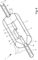
- Fig. 1 schematically shows a plan view or front view of a first preferred embodiment of a rotary tube 1 according to the invention for a (not shown) rotary kiln.
- This basically comprises a rotary kiln 1 or its reactor part at least partially surrounding the heating device.
- the reactor part can be arranged in or above a dish-shaped heating device.
- the rotary tube 1 is rotationally symmetrical about an axis of rotation R, which specifies the axial direction here.
- the rotary tube 1 is designed for the production of activated carbon in a three-stage process, in the first preferred embodiment for the sulfonation, carbonation and activation of polymeric starting materials in a batch process.
- polymeric starting materials are precursors of ion exchange resins (ie, unsulfonated ion exchange resins) are used, in particular divinylbenzene cross-linked polystyrene resins.
- the rotary tube 1 has a rotary tube body 2 and mixing sections 3 for mixing a load 4 and the mixing sections 3 have mixing elements 6 fastened to an inner side 5 of the rotary tube body 2 and firmly connected to the inner side 5.
- the first preferred embodiment of the rotary tube 1 according to the invention has three mixing sections 3 with a plurality of, preferably 30 mixing elements 6.
- Fig. 1 the mixing elements 6 are shown in dashed lines.
- the rotary tubular body 2 and the mixing elements 6 consist at least substantially of quartz glass.
- the rotary tube 1 allows the production of activated carbon while avoiding or minimizing contamination of the activated carbon, in particular by metal traces, at the same time a very good mixing of the load 4, high throughputs, a low rejects and high degrees of activation of the produced activated carbon can be achieved. With the rotary tube 1 can thus produce high-quality activated carbon, the ultrapure requirements, for example in the pharmaceutical sector, sufficient.
- the rotary tube 1 has a high temperature resistance and withstands the very corrosive conditions of carbonization.
- the rotary tube 1 has a high resistance to a wide range of elements and compounds, in particular acids, especially sulfuric acid on.
- the rotary tube 1 enables the sulfonation, carbonation and activation to be carried out in a batch process in a single apparatus.
- the mixing elements 6 are attached to the inner side 5 of the rotary tubular body 2 by means of a binder or attached and prepositioned.
- the mixing elements 6, the binder and the rotary tubular body 2 are firmly connected to each other by low-stress annealing and preferably post-annealing.
- each mixing element 6 has been connected to the rotary tubular body 2 in a separate step.
- stresses in the contact area between the individual mixing elements 6 and the rotary tubular body 2 are eliminated or minimized: This leads to a very stable rotary tube 1 and prevents damage, in particular Cracks, in the rotary tube 1.
- two mixing elements 6 are preferably attached at the same time as far as possible from each other distant positions on the inside 5 of the rotary tubular body 2.
- the mixing elements 6 are permanently or permanently, in particular materially, preferably connected by fusing with the rotary tubular body 2. In cohesive connections, the connection partners are held together by atomic or molecular forces. This leads to a stable connection between the mixing elements 6 and the rotary tubular body 2.
- the contact region between the rotary tubular body 2 and the mixing elements 6 is at least substantially free of residual stresses.
- residual stress refers to mechanical stresses that prevail in a body where no external forces attack and which is in thermal equilibrium. This residual stress freedom has been achieved in that not all mixing elements 6 have been firmly connected to the inner side 5 of the rotary tubular body 2 at the same time. This was done in at least two steps.
- each mixing element 6 is firmly connected to the inner side 5 separately.
- the mixing elements 6 are designed and / or arranged such that the load 4 is at least substantially moved or mixed during operation of the rotary tube 1 in the radial direction, in particular no or only a slight transport of the load 4 in the axial Direction takes place. Then the loading material 4 does not accumulate at one end of the rotary tube 1 during the production process, but remains distributed over at least a substantial part of the length of the rotary tube 1 and is thoroughly mixed with the aid of the mixing elements 6 according to the invention during rotation of the rotary tube 1.
- the term "length" of the rotary tube 1 or of the rotary tube body 2 designates the extent or extent of the rotary tube 1 or of the rotary tube body 2 in the axial direction.
- the rotary tubular body 2 has a central axial section 7 with a first inner cross section, two outer axial sections 8, each having a second inner cross section and two transition sections 9, each with a tapered third inner cross section.
- the central axial section 7 can also be referred to as main reactor and the outer axial section 8 as holding tubes.
- the rotary tube 1 is rotatably mounted on the outer axial sections 8.
- the mixing elements 6 are preferably arranged in the central axial section 7.
- the central axial portion 7 and the two outer axial portions 8 are cylindrical, namely each formed as a straight hollow cylinder.
- the two transition sections 9 are conical or frustoconical.
- the first inner cross section and / or the second inner cross section is at least substantially uniform over its entire length, namely circular.
- the first inner cross section of the central axial section 7 is greater than the second inner cross section of the two outer axial sections 8 Fig. 1
- the inner diameter of the central axial section 7 is greater than the inner diameter of the two outer axial sections 8.
- the central axial section 7 is here arranged between the two transitional sections 9 and the two outer axial sections 8.
- each transition section 9 is arranged between the central axial section 7 and in each case one of the two outer axial sections 8.
- the two transition sections 9 each represent a connecting element between the central axial section 7 and the outer axial sections 8.
- the conical or frustoconical shape of the transition sections 9 tapers from an inner diameter corresponding to the inner diameter of the central axial section 7. to an inner diameter that corresponds to the inner diameter of the two outer axial sections 8.
- the central axial section 7 is preferably first drawn from quartz glass. Subsequently or simultaneously, the two outer axial sections 8 are drawn from quartz glass. Then, the mixing elements 6 are prepared and then, as already described above, individually or in groups thermally attached to the inside 5 of the rotary tubular body 2 by means of a binder and then post-treated individually or in groups. Subsequently, the outer axial sections 8 are glued to the tapered side of the transition sections 9. Finally, the transition sections 9 glued on its non-tapered side to the central axial portion 7. Here too, a subsequent merging can take place.
- the central axial section 7 has an inner diameter of 200 mm to 1,500 mm, preferably 220 mm to 1,000 mm, more preferably 250 mm to 750 mm, particularly preferably 260 mm to 500 mm, in particular at least substantially 300 mm.
- the length of the central axial section 7 is preferably 30% to 1,000%, preferably 60% to 500%, more preferably 100% to 300%, particularly preferably 120% to 200%, in particular at least substantially 175% of the size of the inner diameter of the central axial section 7.
- the length of the central axial section 7 is preferably 100 mm to 3,000 mm, preferably 200 mm to 2,000 mm, more preferably 300 mm to 1,000 mm, particularly preferably 400 mm to 700 mm, in particular at least substantially 520 mm.
- the inner diameter of the two outer axial sections 8 is preferably 1% to 75%, preferably 5% to 60%, more preferably 10% to 40%, particularly preferably 15% to 30%, in particular at least substantially 20%, of the size of the inner diameter
- the inner diameter of the two outer axial sections 8 is preferably 10 mm to 200 mm, preferably 20 mm to 150 mm, more preferably 30 mm to 100 mm, particularly preferably 40 mm to 80 mm, in particular at least Essentially 65 mm.
- the length of the two outer axial sections 8 is preferably in each case 10% to 200%, preferably 20% to 150%, more preferably 30% to 100%, particularly preferably 40% to 75%, in particular at least substantially 50% of the length of absolutely, the length of the two outer axial sections 8 is preferably 50 mm to 1,000 mm, preferably 100 mm to 750 mm, more preferably 150 mm to 500 mm, particularly preferably 200 mm to 300 mm, in particular at least substantially 250 mm.
- the length of the two transition sections 9 is preferably in each case 1% to 100%, preferably 2% to 80%, more preferably 5% to 60%, particularly preferably 10% to 40%, in particular at least substantially 20% of the length of the central axial section 7.
- the length of the two transition sections 9 is preferably 10 mm to 500 mm, preferably 25 mm to 400 mm, more preferably 50 mm to 300 mm, more preferably 75 mm to 200 mm, in particular at least substantially 100 mm.
- the length of the rotary tube 1 is preferably 120% to 700%, preferably 150% to 500%, more preferably 175% to 400%, particularly preferably 200% to 300%, in particular at least substantially 235% of the length of the central axial section 7.
- the length of the rotary tube 1 is preferably 200 mm to 6,000 mm, preferably 500 mm to 4,000 mm, more preferably 1,000 mm to 2,000 mm, in particular at least substantially 1220 mm.
- the rotary tube 1 has at one or both of the outer axial sections 8 a backflow protection and / or overflow protection for solid and / or liquid materials, which are located in the central axial section 7, in particular for the sulfuric acid and / or during the sulfonation.
- the backflow protection or overflow protection in particular acid reflux protection, protects against a return or overflow of the load 4, in particular the sulfuric acid before and / or during the sulfonation, in one or both of the outer axial sections 8.
- the backflow protection or overflow protection protects even in a Filling the rotary tube 1 before an overflow of the filling material 4 in one or both of the outer axial sections eighth
- the backflow protection or overflow protection is particularly important in the treatment with sulfuric acid, especially in the sulfonation, of importance.
- the backflow protection prevents the sulfuric acid from flowing into one or both of the outer axial sections 8 during operation of the rotary tube 1, in particular during the sulfonation. Due to the backflow protection or overflow protection, the sulfuric acid ultimately remains in the central axial section 7.
- the return protection or overflow protection of the rotary tube 1 is formed by one or both of the outer axial sections 8 projecting in the axial direction in each case with its end 10 adjacent to the respective transition section 9 into the respective transition section 9. This is in the Fig. 1 and 3 exaggerated to better Veranschautichung.
- the projection of the respective protruding end 10 of the outer axial sections 8 in the respectively adjacent transition section 9 is 3% to 50%, preferably 5% to 30%, more preferably 10% to 20%, in particular substantially 15% of the length of one of absolutely, the projection of the respective protruding end 10 of the outer axial sections 8 in the respectively adjacent transition section 9 is preferably at least 2 mm, preferably at least 5 mm, more preferably at least 7 mm, in particular at least substantially 10 mm.
- the mixing elements 6 are plate-shaped, ie flat and even.
- the mixing elements 6 extend at least substantially in the axial direction, ie the largest extent of the mixing elements 6 extends in the axial direction.
- the mixing elements 6 extend axially parallel, ie parallel to the axis of rotation R of the rotary tube. 1
- all mixing elements 6 have the same length, the same width and the same thickness.
- the term “width” of the mixing elements 6 designates the expansion of the mixing elements 6 in the radial direction of the rotary tubular body 2.
- the term “thickness” of the mixing elements 6 designates the expansion of the mixing elements 6 in the circumferential direction of the rotary tubular body 2.
- the same dimensioning of the mixing elements 6 ultimately means Component identity, resulting in savings in manufacturing the mixing elements 6 and a simpler and more cost-effective installation of the mixing elements 6 leads.
- the mixing elements 6 are at least substantially completely inclined in the direction of rotation D of the rotary tube 1 to the inside 5 of the rotary tubular body 2 in each case by an inclination angle ⁇ .
- Fig. 2 illustrates, in the schematic section through the rotary tube 1 from Fig. 1 along the section line II / II off Fig. 1 is shown.
- the mixing elements 6 can be inclined relative to their length only in sections in the direction of rotation D of the rotary tube 1 to the inside 5 of the rotary tubular body 2 each by the inclination angle a, ie the mixing elements 6 then no longer run axially parallel.
- the inclination of the mixing elements 6 leads to a better mixing of the load 4.
- the mixing elements 6 protrude in the radial direction by no more than the size of the radius of the rotary tubular body 2 into the rotary tubular body 2.
- the width of the mixing elements 6 is not more than the radius of the rotary tubular body 2 divided by the cosine of the inclination angle ⁇ .
- the respective angle of inclination ⁇ of the mixing elements 6 is measured between the radius of the rotary tubular body 2 emanating from the contact area between the rotary tubular body 2 and the respective mixing element 6 and the plane passing through the respective mixing element 6 in the axial direction.
- the width of the mixing elements 6 is shown in each case by a dashed line.
- the respective inclination angle ⁇ of the mixing elements 6 is 1 ° to 60 °, preferably 20 ° to 55 °, more preferably 40 ° to 50 °, in particular at least substantially 45 °.
- the respective angle of inclination ⁇ of the mixing elements 6 is measured between the radius of the rotary tubular body 2 emanating from the contact area between the rotary tubular body 2 and the respective mixing element 6 and the plane passing through the respective mixing element 6 in the axial direction.
- the respective angle of inclination ⁇ of the mixing elements 6 is between 35 ° and 55 °, in particular at least substantially 45 °, if the respective width of the mixing elements 6 is at least substantially 25% of the respective length of the mixing elements 6 , especially 40 mm to 60 mm, preferably at least substantially 50 mm. In this arrangement or inclination of the mixing elements 6 results in a very good mixing of the load 4.
- the length of the mixing elements 6 is 10% to 100%, preferably 20% to 75%, more preferably 30% to 50%, in particular at least substantially 40% of the length of the central axial section 7.
- the length of the mixing elements 6 is preferably 50 mm to 500 mm, preferably 100 mm to 300 mm, in particular substantially 200 mm.
- the width of the mixing elements 6 is 5% to 50%, preferably 10% to 40%, more preferably 20% to 30%, in particular at least substantially 25% of the length of the mixing elements 6.
- the width of the mixing elements 6 is preferably 10 mm to 100 mm, preferably 25 mm to 75 mm, in particular substantially 50 mm.
- the thickness of the mixing elements 6 is 0.1% to 5%, preferably 0.5% to 3%, more preferably 1% to 2%, in particular at least substantially 1.5% of the length of the mixing elements 6.
- the thickness is absolute the mixing elements 6 preferably 1 mm to 10 mm, preferably 2 mm to 5 mm, in particular substantially 3 mm.
- the mixing elements 6 have a length of 200 mm, a width of 50 mm and a thickness of 3 mm. In this dimensioning of the mixing elements 6 results on the one hand a very good mixing of the load 4 and on the other a contact surface between the mixing elements 6 and the rotary tube body 2, which has proven to be advantageous in terms of induced residual stresses and the stability of the rotary tube 1.
- mixing elements 6 are mounted or mounted circumferentially spaced from one another in the central axial section 7.
- Fig. 1 the first row can be seen in the left part of the central axial section 7.
- the first row of the mixing elements 6 forms a mixing section 3.
- the length of the first row corresponds to the length of the mixing elements 6 of the first row.
- the mixing elements 6 of the second row can be seen in the middle part of the central axial section 7.
- the mixing elements 6 of the second row are offset here relative to the mixing elements 6 of the first row in the axial direction, in particular overlapping, and / or attached offset in the circumferential direction.
- the mixing elements 6 of the second row are not fixed in the axial direction adjacent to the mixing elements 6 of the first row.
- a mixing element 6 of the first row in the circumferential direction next to a mixing element 6 of the second row can be seen alternately. In this arrangement, the mixing elements 6 results in a very good mixing of the load 4.
- a plurality of, preferably ten, mixing elements 6 are mounted in the central axial section 7 in a third row spaced apart from one another in the circumferential direction.
- the mixing elements 6 of the third row are offset here relative to the mixing elements 6 of the second row in the axial direction, in particular overlapped and mounted offset in the circumferential direction. Further, here the mixing elements 6 of the third row are fixed spaced from the mixing elements 6 of the first row in the axial direction.
- a mixing element 6 of the first row extends with a mixing element 6 of the third row in the axial direction on an axis-parallel straight line. The mixing elements 6 of the first and third rows are thus aligned in the axial direction.
- the mixing elements 6 of the third row are concealed by the mixing elements 6 of the first row, since the mixing elements 6 of the third row in FIG Fig. 2 run behind the mixing elements 6 of the first row. In this arrangement, the mixing elements 6 results in a very good mixing of the load 4.
- the second and third rows each form a mixing section 3.
- the mixing elements 6 and / or all rows have the same distance from each other in the circumferential direction.
- FIG. 3 schematically shows a perspective view of the first preferred embodiment of the rotary tube 1 according to the invention Fig. 1 wherein a part of the rotary tube 1 is cut out.
- Fig. 4 schematically shows a section through the rotary tube 1 from Fig. 1 along the section line IV / IV off Fig. 2
- Fig. 5 schematically shows a section through the rotary tube 1 from Fig. 1 along the section line V / V off Fig. 2
- These figures serve to better illustrate the preferred arrangement of the mixing elements 6 of the rotary tube 1 from Fig. 1 ,
- Fig. 6 schematically shows a perspective view of a second preferred embodiment of the rotary tube 1 according to the invention, wherein a part of the rotary tube 1 is cut open.
- at least two, preferably three rows, ie mixing sections 3 are formed by a preferably one-piece mixing element 6 fastened to the inside 5 of the rotary tubular body 2.
- the mixing element 6 preferably has a plurality of, preferably three, mixing regions 11 running in the axial direction and a plurality of, preferably two, separator regions 12 extending in the circumferential direction.
- the separator regions 12 prevent or minimize axial transport of the load material 4.
- This embodiment enables a simple and cost-effective implementation of a rotary tube 1 according to the invention. Otherwise, separate or also associated separator regions 12 in the first preferred embodiment of FIG Fig. 1 be provided.
- rows or mixing sections 3 which are formed by a mixing element 6, more rows or mixing sections 3 may be arranged, for. B. with several mixing elements 6 - as described in the first preferred embodiment.
- the mixing areas are based on their length at least substantially sections, preferably completely, in the direction of rotation D of the rotary tube 1 to the inside 5 of the rotary tubular body 2 by an inclination angle ⁇ inclined.
- the respective inclination angle ⁇ of the mixing regions 11 is preferably 1 ° to 60 °, preferably 20 ° to 55 °, more preferably 40 ° to 50 °, in particular at least substantially 45 °. Due to the inclination of the mixing regions 11, the mixing of the load 4 is improved.
- the rotary tubular body 2 and the mixing elements 6 preferably consist at least substantially of a quartz glass whose content of the substances specified in Table 1 does not exceed the maximum values given in this table.
- Table 1 Salary is at most preferably at most aluminum 40 ppm 20 ppm calcium 3 ppm 1.5 ppm chrome 0.1 ppm 0.05 ppm copper 0.1 ppm 0.05 ppm iron 2 ppm 1 ppm potassium 3 ppm 1.5 ppm lithium 3 ppm 1.5 ppm manganese 0.2 ppm 0.1 ppm sodium 3 ppm 1.5 ppm nickel 0.04 ppm 0.02 ppm titanium 4 ppm 2 ppm zirconium 5.4 ppm 2.7 ppm OH 90 ppm 45 ppm
- the quartz glass from which the rotary tubular body 2 and the mixing elements 6 at least substantially consist of the first hydrolysis class according to DIN 12111 and / or the first class of acid according to DIN 12116 and / or the first class of alkali according to DIN 52322 assigned.
- the quartz glass used preferably has an upper expansion limit of at least 1100 ° C., more preferably at least 1200 ° C., in particular at least substantially 1.204 ° C.
- the quartz glass used preferably has a lower expansion limit of at least 900 ° C., preferably at least 1000 ° C., in particular at least substantially 1.054 ° C.
- the quartz glass used allows a short-term service temperature of at least 1200 ° C, preferably at least 1300 ° C.
- the quartz glass used allows a long-term service temperature of at least 1000 ° C, preferably at least 1100 ° C.
- the rotary tube 1 according to the invention can be developed such that the outer axial sections 8 each have an inlet and / or outlet opening for introducing, discharging and passing gases, for example for introducing Inert gases for the carbonization phase in the production of activated carbon and for introducing oxidizing gases for the activation phase in the activated carbon production, as well as for filling and emptying of the load 4 have.
- the outer axial sections 8 are hollow sections.
- the rotary tube 1 according to the present invention is used in rotary kilns for producing activated carbon.
- the present invention - according to a second aspect of the present invention - is thus a rotary kiln for the production of activated carbon by means of sulfonation, carbonation and activation in a discontinuous process, which comprises the above-described rotary tube 1 according to the present invention.
- the rotary kiln preferably has a heating device for direct and / or indirect heating of the rotary tube 1, in particular of the central axial section 7.
- Another object of the present invention - according to a third aspect of the invention - is the use of a rotary kiln 1 or a rotary kiln as described above for the production of activated carbon by means of sulfonation, carbonization and activation in a discontinuous process.
- the preparation of the activated carbon is preferably carried out on the basis of carbonaceous starting materials, in particular organic polymers, very particularly divinylbenzene-crosslinked polystyrenes, preferably in the form of small granules or beads.
- the carbonization is preferably carried out at temperatures of 100 ° C to 750 ° C, preferably 150 ° C to 650 ° C, in particular 200 ° C to 600 ° C, more preferably under inert or at most slightly oxidizing atmosphere. Carbonation may be preceded by a stage of precarbonization or pre-carbonization.
- the activation is preferably carried out at temperatures of 700 ° C to 1200 ° C, preferably 800 ° C to 1100 ° C, more preferably 850 ° C to 1000 ° C.
- the activation is carried out under controlled or selectively oxidizing conditions, in particular under a controlled oxidizing atmosphere.
- Fig.1 to 6 illustrated embodiments represent only one, but preferred subset of the variants of a rotary tube 1 according to the invention.
- Example 1 Rotary tube of quartz glass according to the invention with mixing sections and anti-reverse protection on both sides (invention)
- the entire carbonized material (38.5 kg) was subsequently gassed at 900 ° C with a mixture of 75% nitrogen and 25% steam and cooled after two hours of activation in the rotary tube. After this activation, a spherical activated carbon completely free of iron resulted, with a BET surface area of about 1475 m 2 / g and a compressive strength of 45 Newton per bead of about 0.5 mm diameter. The yield was about 66% based on carbonized material.
- Example 2 Rotary tube made of quartz glass without mixing sections and without backflow protection (comparison)
- Example 1 was repeated in a conventional rotary tube made of quartz glass without mixing sections and without backflow protection, but with the otherwise same dimensions as in Example 1.
- a certain loss of sulfuric acid occurred, which flowed partly into the holding tubes of the rotary tube (as well as parts of the polymer material to be sulfonated).
- the carbonation and activation times were each longer by about 2 hours compared to example 1 due to the reduced mixing.
- the yield after activation was significantly lower than in example 1 (yield, based on carbonized material: about 48%).
- the BET surface area after activation was only about 1044 m 2 / g with a compressive strength of only 33 Newton per bead of about 0.5 mm diameter. Also, a small portion of the load was entrained during activation with the activation gas due to the lack of backflow protection.
- Example 3 Rotary tube made of quartz glass without mixing sections and without backflow protection, but with knob-like, protruding into the interior of the rotary tube indentations in the rotary tube shell (comparison)
- Example 1 was repeated in a conventional rotary tube made of quartz glass without mixing sections and without backflow protection, but with knob-like, protruding into the interior of the rotary tube indentations in the rotary tube jacket and the otherwise same dimensions as in Example 1.
- a certain loss of sulfuric acid occurred, which flowed partly into the holding tubes of the rotary tube (as well as parts of the polymer material to be sulfonated).
- the carbonation or activation time was extended by about 1.5 hours or 1 hour compared to Example 1 due to the deterioration of mixing, but was slightly improved compared to Example 2 due to the knob-like, projecting into the interior of the rotary tube indentations.
- Example 1 The yield after activation was significantly lower than in Example 1 (yield, based on carbonized material: about 55%).
- the BET surface area after activation was only about 1,205 m 2 / g with a compressive strength of only 38 Newton per bead of about 0.5 mm diameter. Also, a small portion of the load was entrained during activation with the activation gas due to the lack of backflow protection.
- the above examples impressively prove the superiority of the rotary kiln or rotary kiln according to the invention.
- An efficient mixing and turbulence of the load is achieved, along with shorter process times and improved products.
- an undesirable leakage of the sulfuric acid in the sulfonation as well as the load due to the backflow protection is prevented in an efficient manner.
- the rotary kiln or rotary kiln according to the invention also makes it possible for the first time to carry out the overall process in a rotary kiln or rotary kiln made of quartz glass.
Landscapes
- Engineering & Computer Science (AREA)
- Chemical & Material Sciences (AREA)
- Organic Chemistry (AREA)
- Mechanical Engineering (AREA)
- General Engineering & Computer Science (AREA)
- Inorganic Chemistry (AREA)
- Carbon And Carbon Compounds (AREA)
Claims (15)
- Tube rotatif (1) pour un four rotatif, conçu pour la fabrication de charbon actif, plus particulièrement au moyen d'une sulfonation, d'une carbonisation et d'une activation de matériaux de départ polymères dans un processus discontinu, avec un corps de tube rotatif (2) et plusieurs portions de mélange (3) avec plusieurs éléments de mélange (6) pour le mélange d'un produit de chargement (4), le corps de tube rotatif (2) et les éléments de mélange (6) étant constitués au moins essentiellement de verre de quartz,
caractérisé en ce que
les éléments de mélange (6) sont fixés au côté interne (5) du corps de tube rotatif (2) et fermement reliés avec le côté interne (5), les éléments de mélange (6) étant reliés de manière ferme et durable avec le corps de tube rotatif (2) et les éléments de mélange (6) présentant la forme de plaques ;
le corps de tube rotatif (2) comprenant une portion axiale centrale (7) avec une première section transversale interne, deux portions axiales externes (8) avec chacune une deuxième section transversale interne et deux portions de transition (9) avec chacune une troisième section transversale interne qui se rétrécit ; et
le tube rotatif (1) comprend, au niveau d'une ou de deux portions axiales externes (8), une protection anti-retour et/ou une protection anti-débordement pour des matériaux solides et/ou liquides, la protection anti-retour et/ou la protection anti-débordement étant conçue de façon à ce qu'un ou les deux portions axiales externes (8) dépasse chacune dans la direction axiale, avec son extrémité (10) proche de la portion de transition (9) correspondante, dans la portion de transition (9) correspondante. - Tube rotatif selon la revendication 1, caractérisé en ce que
l'élément de mélange (6) est monté ou fixé à l'aide d'un moyen de liaison au côté interne (5) du corps de tube rotatif (2) et/ou
l'élément de mélange (6) et le corps de tube rotatif (2) sont reliés entre eux, le cas échéant, par l'intermédiaire du moyen de liaison, par recuit sans tension, et de préférence par post-cuisson et/ou
l'élément de mélange (6) est disposé dans la portion axiale centrale (7). - Tube rotatif selon la revendication 1 ou 2, caractérisé en ce que
la portion axiale centrale (7) et/ou les deux portions axiales externes (8) présentent une forme cylindrique, plus particulièrement une forme de cylindre creux et droit et/ou
les deux portions de transition (9) présentent une forme conique et/ou tronconique et/ou
la première section transversale interne de la portion axiale centrale (7) est supérieure à la deuxième section transversale interne des deux portions axiales externes (8) et/ou
la portion axiale centrale (7) est disposée entre les deux portions de transition (9) et/ou les deux portions axiales externes (8) et/ou
chaque portion de transition (9) est disposée entre la portion axiale centrale (7) et chacune des deux portions axiales externes (8) et/ou
la portion axiale centrale (7) présente un diamètre intérieur de 200 mm à 1500 mm, de préférence de 200 mm à 1000 mm, de préférence de 250 mm à 750 mm, de préférence de 260 mm à 500 mm plus particulièrement d'au moins 300 mm. - Tube rotatif selon l'une des revendications précédentes, caractérisé en ce que
la protection anti-retour et/ou la protection anti-débordement se trouve(nt) dans la transition entre la portion de transition (9) et la portion axiale externe (8) et/ou
la protection anti-retour et/ou la protection anti-débordement étant conçue(s) de façon à empêcher un retour et/ou un débordement du produit de chargement (4), plus particulièrement de l'acide sulfurique avant et/ou pendant la sulfonation, dans une ou les deux portions axiales externes (8) et/ou
la saillie de l'extrémité en saillie (10) de la portion axiale externe (8) est, dans la portion de transition (9) adjacente, d'au moins 2 mm, de préférence d'au moins 5 mm, de préférence d'au moins 7 mm, plus particulièrement d'au moins 10 mm. - Tube rotatif selon l'une des revendications précédentes, caractérisé en ce que
les éléments de mélange (6) s'étendent au moins globalement dans la direction axiale, de préférence de manière parallèle et/ou
tous les éléments de mélange (6) présentent la même longueur et/ou largeur et/ou épaisseur et/ou
les éléments de mélange (6) sont inclinés, par rapport à leur longueur, au moins globalement partiellement, de préférence entièrement, dans le sens de rotation (D) du tube rotatif (1) par rapport à un côté interne (5) du corps de tube rotatif (2) d'un angle d'inclinaison (α) et/ou
tous les éléments de mélange (6) présentent le même angle d'inclinaison (α) et/ou
l'angle d'inclinaison (α) des éléments de mélange (6), mesuré entre le rayon du corps de tube rotatif (2) partant de la zone de contact entre le corps de tube rotatif (2) et l'élément de mélange (6) correspondant et le plan s'étendant dans la direction axiale à travers l'élément de mélange (6) correspondant, est de l'ordre de 1 à 60°, de préférence de 20 à 55°, de préférence de 40 à 50°, plus particulièrement d'au moins 45° et/ou
la longueur des éléments de mélange (6) représente de 10 % à 100 %, de préférence de 20 % à 75 %, de préférence de 30 % à 50 %, plus particulièrement d'au moins 40 % de la longueur de la portion axiale centrale (7) et/ou
les éléments de mélange (6) présentent une longueur de 50 mm à 500 mm, de préférence de 100 mm à 300 mm, plus particulièrement d'au moins 200 mm. - Tube rotatif selon l'une ou plusieurs revendications précédentes, caractérisé en ce que
dans la portion axiale centrale (7), sont fixés, avec une certaine distance entre eux, de préférence dix éléments de mélange (6) dans une première rangée dans la direction circonférentielle et/ou
dans la portion axiale centrale (7), sont fixés, avec une certaine distance entre eux, de préférence dix éléments de mélange (6) dans une deuxième rangée dans la direction circonférentielle et/ou
les éléments de mélange (6) de la deuxième rangée sont décalés par rapport aux éléments de mélange (6) de la première rangée dans la direction axiale, plus particulièrement sont fixés de manière superposée et/ou décalée dans la direction circonférentielle. - Tube rotatif selon l'une ou plusieurs des revendications précédentes, caractérisé en ce que
dans la portion axiale centrale (7), sont fixés, avec une certaine distance entre eux, de préférence dix éléments de mélange dans une troisième rangée dans la direction circonférentielle et/ou
les éléments de mélange (6) de la troisième rangée sont décalés par rapport aux éléments de mélange (6) de la deuxième rangée dans la direction axiale, plus particulièrement sont fixés de manière superposée et/ou décalée dans la direction circonférentielle et/ou
les éléments de mélange (6) de la troisième rangée sont écartés des éléments de mélange (6) la première rangée dans la direction axiale et/ou
un élément de mélange (6) de la première rangée s'étend, avec un élément de mélange (6) de la troisième rangée, dans la direction axiale, sur une droite parallèle. - Tube rotatif selon l'une ou plusieurs des revendications précédentes, caractérisé en ce que
au moins deux portions de mélange (3) sont constituées d'au moins un élément de mélange (6), de préférence d'une seule pièce, fixé au côté interne (5) du corps de tube rotatif (2) et relié fermement avec le côté interne (5) et/ou
l'élément de mélange (6) comprend plusieurs zones de mélange (11) s'étendant dans la direction axiale et plusieurs zones de séparation (12) s'étendant dans la direction circonférentielle. - Tube rotatif selon l'une ou plusieurs des revendications précédentes, caractérisé en ce que les zones de mélange (11) sont inclinées, par rapport à leur longueur, au moins globalement partiellement, de préférence entièrement, dans le sens de rotation (D) du tube rotatif (1), par rapport au côté interne (5) du corps de tube rotatif (2), d'un angle d'inclinaison (α).
- Tube rotatif selon l'une ou plusieurs des revendications précédentes, caractérisé en ce que l'angle d'inclinaison (α) des zones de mélange (11), mesuré entre le rayon du corps de tube rotatif (2) partant de la zone de contact entre le corps de tube rotatif (2) et la zone de mélange (11) correspondante et le plan s'étendant dans la direction axiale à travers la zone de mélange (11) correspondante, est de l'ordre de 1 à 60°, de préférence de 20 à 55°, de préférence de 40 à 50°, plus particulièrement d'au moins 45°.
- Tube rotatif selon l'une ou plusieurs des revendications précédentes, caractérisé en ce que le corps de tube rotatif (2) et l'élément de mélange (6) sont constitués au moins globalement d'un verre de quartz, le verre de quartz présentant une teneur en aluminium de 40 ppm maximum, de préférence de 20 ppm maximum.
- Tube rotatif selon l'une ou plusieurs des revendications précédentes, caractérisé en ce que les portions axiales externes (8) présentent chacune une ouverture d'admission et/ou d'évacuation pour l'introduction, l'évacuation et le passage de gaz ainsi que pour le remplissage et la vidange du produit de chargement (4).
- Four rotatif pour la fabrication de charbon actif à l'aide d'une sulfonation de carbonisation et d'activation dans un processus discontinu, comprenant un tube rotatif (1) selon les revendications 1 à 12.
- Four rotatif selon la revendication 13, caractérisé en ce que le four rotatif comprend un dispositif de chauffage pour le chauffage direct et/ou indirect du tube rotatif (1).
- Utilisation d'un tube rotatif selon les revendications 1 à 12, ou d'un four rotatif selon les revendications 13 ou 14 pour la fabrication de charbon actif à l'aide d'une sulfonation, d'une carbonisation et d'une activation dans un processus discontinu.
Applications Claiming Priority (3)
| Application Number | Priority Date | Filing Date | Title |
|---|---|---|---|
| DE102013008412 | 2013-05-17 | ||
| DE201310009961 DE102013009961A1 (de) | 2013-05-17 | 2013-06-14 | Drehrohr und Drehrohrofen zur Herstel1ung von Aktivkohle |
| PCT/EP2014/057056 WO2014183927A1 (fr) | 2013-05-17 | 2014-04-08 | Tube rotatif et four tubulaire rotatif servant à produire du charbon actif |
Publications (2)
| Publication Number | Publication Date |
|---|---|
| EP2997321A1 EP2997321A1 (fr) | 2016-03-23 |
| EP2997321B1 true EP2997321B1 (fr) | 2016-12-28 |
Family
ID=50630762
Family Applications (1)
| Application Number | Title | Priority Date | Filing Date |
|---|---|---|---|
| EP14720914.2A Active EP2997321B1 (fr) | 2013-05-17 | 2014-04-08 | Tube rotatif et four tubulaire rotatif servant à produire du charbon actif |
Country Status (4)
| Country | Link |
|---|---|
| US (1) | US9746242B2 (fr) |
| EP (1) | EP2997321B1 (fr) |
| DE (1) | DE102013009961A1 (fr) |
| WO (1) | WO2014183927A1 (fr) |
Families Citing this family (4)
| Publication number | Priority date | Publication date | Assignee | Title |
|---|---|---|---|---|
| DE202016100320U1 (de) | 2015-12-10 | 2016-12-28 | BLüCHER GMBH | Aktivkohle, insbesondere partikuläre Aktivkohle, insbesondere mit definierten Porositätseigenschaften |
| CN105692612B (zh) * | 2016-03-31 | 2018-07-27 | 神华集团有限责任公司 | 一种煤基活性炭的氧化炭化装置及方法 |
| RU2725256C1 (ru) * | 2019-10-16 | 2020-06-30 | Федеральное государственное бюджетное образовательное учреждение высшего образования "Кубанский государственный аграрный университет имени И.Т. Трубилина" | Вращающая печь для обжига шлама для приготовления цементного клинкера |
| US11834338B1 (en) | 2022-05-24 | 2023-12-05 | John W. Black | Continuous carbonaceous matter thermolysis and pressurized char activation with hydrogen production |
Family Cites Families (12)
| Publication number | Priority date | Publication date | Assignee | Title |
|---|---|---|---|---|
| US2939693A (en) * | 1956-08-06 | 1960-06-07 | Southern Lightweight Aggregate | Rotary kiln |
| ES2233634T3 (es) * | 2000-04-28 | 2005-06-16 | Blucher Gmbh | Procedimiento para producir carbon activo de forma esferica. |
| DE10142764A1 (de) * | 2001-08-31 | 2003-03-27 | Bohle L B Pharmatech Gmbh | Verfahren und Vorrichtung zum Trocknen von pharmazeutischen Granulaten, Pellets od.dgl. |
| JPWO2005007572A1 (ja) * | 2003-07-18 | 2006-08-31 | 則幸 山崎 | 炭化物製造装置及び炭化物製造方法 |
| DE102004036109B4 (de) * | 2004-07-08 | 2006-08-03 | BLüCHER GMBH | Drehrohr für die Aktivkohleherstellung und seine Verwendung |
| DE102005036607A1 (de) * | 2005-07-28 | 2007-02-08 | BLüCHER GMBH | Drehrohrofen für die Herstellung von Aktivkohle |
| EP1903292B1 (fr) * | 2006-09-19 | 2011-11-16 | Blücher GmbH | Four rotatif pour la préparation de charbon actif doté d'une géométrie rotative modifiée |
| DE202006017001U1 (de) * | 2006-09-19 | 2007-10-25 | BLüCHER GMBH | Drehrohrofen für die Aktivkohleherstellung mit veränderter Drehrohrgeometrie |
| DE102008049598A1 (de) * | 2008-09-30 | 2010-04-01 | Heraeus Quarzglas Gmbh & Co. Kg | Verfahren und Vorrichtung für die Reinigung von SiO2-Körnung |
| CN101985558B (zh) * | 2010-08-19 | 2012-01-04 | 西峡龙成特种材料有限公司 | 煤物质的分解设备 |
| CA2783082C (fr) * | 2012-04-02 | 2013-11-19 | Andrew Marszal | Convertisseur de dechets avec tambour rotatif |
| US10864488B2 (en) * | 2013-06-20 | 2020-12-15 | Hatch Pty Ltd | Anti-segregation mixer |
-
2013
- 2013-06-14 DE DE201310009961 patent/DE102013009961A1/de not_active Ceased
-
2014
- 2014-04-08 WO PCT/EP2014/057056 patent/WO2014183927A1/fr active Application Filing
- 2014-04-08 EP EP14720914.2A patent/EP2997321B1/fr active Active
- 2014-04-08 US US14/891,498 patent/US9746242B2/en active Active
Non-Patent Citations (1)
| Title |
|---|
| None * |
Also Published As
| Publication number | Publication date |
|---|---|
| US20160084574A1 (en) | 2016-03-24 |
| EP2997321A1 (fr) | 2016-03-23 |
| WO2014183927A1 (fr) | 2014-11-20 |
| US9746242B2 (en) | 2017-08-29 |
| DE102013009961A1 (de) | 2014-12-04 |
Similar Documents
| Publication | Publication Date | Title |
|---|---|---|
| EP1614987B1 (fr) | Four rotatif pour la production de charbon actif | |
| EP1903292B1 (fr) | Four rotatif pour la préparation de charbon actif doté d'une géométrie rotative modifiée | |
| EP2451744B1 (fr) | Installation et procédé de production de charbon actif | |
| EP1276694B1 (fr) | Procede de production de charbon actif sous forme de billes | |
| EP1654196B1 (fr) | Fabrication de charbon actif | |
| EP2997321B1 (fr) | Tube rotatif et four tubulaire rotatif servant à produire du charbon actif | |
| EP1748269B1 (fr) | Four rotatif pour la fabrication du charbon actif | |
| DE102006010862B4 (de) | Aktivkohle mit katalytischer Aktivität | |
| EP3362407A1 (fr) | Procédé de fabrication de charbon actif et charbon actif obtenu par ce procédé, ainsi que son utilisation | |
| EP0952960B1 (fr) | Charbon actif granule issu de residus de distillation | |
| DE102016101213A1 (de) | Vorrichtung und Verfahren zur Modifizierung poröser Feststoffe | |
| WO2016169638A1 (fr) | Traitement de gaz d'échappement de la production de clinker | |
| EP2106840B1 (fr) | Catalyseur au charbon actif | |
| CN106082172A (zh) | 一种高比表面积制氮碳分子筛的制备方法 | |
| DE202005014318U1 (de) | Drehrohrofen für die Herstellung von Aktivkohle | |
| EP3175889B1 (fr) | Dispositif et procede de carbonatation de solides alcalins | |
| DE202013005362U1 (de) | Drehrohr und Drehrohrofen zur Herstellung von Aktivkohle | |
| DE202006017001U1 (de) | Drehrohrofen für die Aktivkohleherstellung mit veränderter Drehrohrgeometrie | |
| DE102006052377A1 (de) | Drehrohrofen für die Aktivkohleherstellung mit veränderter Drehrohrgeometrie | |
| DE202006003674U1 (de) | Aktivkohle mit katalytischer Aktivität | |
| DE202004011652U1 (de) | Drehrohrofen für die Aktivkohleherstellung | |
| DE4011882C2 (de) | Verfahren zum Calcinieren von zeolithischen Granulaten | |
| DE10040485A1 (de) | Verfahren zur Herstellung einer Kugelkohle |
Legal Events
| Date | Code | Title | Description |
|---|---|---|---|
| PUAI | Public reference made under article 153(3) epc to a published international application that has entered the european phase |
Free format text: ORIGINAL CODE: 0009012 |
|
| 17P | Request for examination filed |
Effective date: 20151001 |
|
| AK | Designated contracting states |
Kind code of ref document: A1 Designated state(s): AL AT BE BG CH CY CZ DE DK EE ES FI FR GB GR HR HU IE IS IT LI LT LU LV MC MK MT NL NO PL PT RO RS SE SI SK SM TR |
|
| AX | Request for extension of the european patent |
Extension state: BA ME |
|
| GRAJ | Information related to disapproval of communication of intention to grant by the applicant or resumption of examination proceedings by the epo deleted |
Free format text: ORIGINAL CODE: EPIDOSDIGR1 |
|
| GRAP | Despatch of communication of intention to grant a patent |
Free format text: ORIGINAL CODE: EPIDOSNIGR1 |
|
| INTG | Intention to grant announced |
Effective date: 20161006 |
|
| GRAS | Grant fee paid |
Free format text: ORIGINAL CODE: EPIDOSNIGR3 |
|
| GRAA | (expected) grant |
Free format text: ORIGINAL CODE: 0009210 |
|
| AK | Designated contracting states |
Kind code of ref document: B1 Designated state(s): AL AT BE BG CH CY CZ DE DK EE ES FI FR GB GR HR HU IE IS IT LI LT LU LV MC MK MT NL NO PL PT RO RS SE SI SK SM TR |
|
| AX | Request for extension of the european patent |
Extension state: BA ME |
|
| REG | Reference to a national code |
Ref country code: GB Ref legal event code: FG4D Free format text: NOT ENGLISH |
|
| REG | Reference to a national code |
Ref country code: CH Ref legal event code: EP |
|
| REG | Reference to a national code |
Ref country code: AT Ref legal event code: REF Ref document number: 857662 Country of ref document: AT Kind code of ref document: T Effective date: 20170115 |
|
| REG | Reference to a national code |
Ref country code: IE Ref legal event code: FG4D Free format text: LANGUAGE OF EP DOCUMENT: GERMAN |
|
| REG | Reference to a national code |
Ref country code: DE Ref legal event code: R096 Ref document number: 502014002346 Country of ref document: DE |
|
| PG25 | Lapsed in a contracting state [announced via postgrant information from national office to epo] |
Ref country code: LV Free format text: LAPSE BECAUSE OF FAILURE TO SUBMIT A TRANSLATION OF THE DESCRIPTION OR TO PAY THE FEE WITHIN THE PRESCRIBED TIME-LIMIT Effective date: 20161228 |
|
| REG | Reference to a national code |
Ref country code: FR Ref legal event code: PLFP Year of fee payment: 4 |
|
| REG | Reference to a national code |
Ref country code: LT Ref legal event code: MG4D |
|
| PG25 | Lapsed in a contracting state [announced via postgrant information from national office to epo] |
Ref country code: GR Free format text: LAPSE BECAUSE OF FAILURE TO SUBMIT A TRANSLATION OF THE DESCRIPTION OR TO PAY THE FEE WITHIN THE PRESCRIBED TIME-LIMIT Effective date: 20170329 Ref country code: NO Free format text: LAPSE BECAUSE OF FAILURE TO SUBMIT A TRANSLATION OF THE DESCRIPTION OR TO PAY THE FEE WITHIN THE PRESCRIBED TIME-LIMIT Effective date: 20170328 Ref country code: LT Free format text: LAPSE BECAUSE OF FAILURE TO SUBMIT A TRANSLATION OF THE DESCRIPTION OR TO PAY THE FEE WITHIN THE PRESCRIBED TIME-LIMIT Effective date: 20161228 Ref country code: SE Free format text: LAPSE BECAUSE OF FAILURE TO SUBMIT A TRANSLATION OF THE DESCRIPTION OR TO PAY THE FEE WITHIN THE PRESCRIBED TIME-LIMIT Effective date: 20161228 |
|
| REG | Reference to a national code |
Ref country code: NL Ref legal event code: MP Effective date: 20161228 |
|
| PG25 | Lapsed in a contracting state [announced via postgrant information from national office to epo] |
Ref country code: FI Free format text: LAPSE BECAUSE OF FAILURE TO SUBMIT A TRANSLATION OF THE DESCRIPTION OR TO PAY THE FEE WITHIN THE PRESCRIBED TIME-LIMIT Effective date: 20161228 Ref country code: RS Free format text: LAPSE BECAUSE OF FAILURE TO SUBMIT A TRANSLATION OF THE DESCRIPTION OR TO PAY THE FEE WITHIN THE PRESCRIBED TIME-LIMIT Effective date: 20161228 Ref country code: HR Free format text: LAPSE BECAUSE OF FAILURE TO SUBMIT A TRANSLATION OF THE DESCRIPTION OR TO PAY THE FEE WITHIN THE PRESCRIBED TIME-LIMIT Effective date: 20161228 |
|
| PG25 | Lapsed in a contracting state [announced via postgrant information from national office to epo] |
Ref country code: NL Free format text: LAPSE BECAUSE OF FAILURE TO SUBMIT A TRANSLATION OF THE DESCRIPTION OR TO PAY THE FEE WITHIN THE PRESCRIBED TIME-LIMIT Effective date: 20161228 |
|
| PG25 | Lapsed in a contracting state [announced via postgrant information from national office to epo] |
Ref country code: SK Free format text: LAPSE BECAUSE OF FAILURE TO SUBMIT A TRANSLATION OF THE DESCRIPTION OR TO PAY THE FEE WITHIN THE PRESCRIBED TIME-LIMIT Effective date: 20161228 Ref country code: RO Free format text: LAPSE BECAUSE OF FAILURE TO SUBMIT A TRANSLATION OF THE DESCRIPTION OR TO PAY THE FEE WITHIN THE PRESCRIBED TIME-LIMIT Effective date: 20161228 Ref country code: EE Free format text: LAPSE BECAUSE OF FAILURE TO SUBMIT A TRANSLATION OF THE DESCRIPTION OR TO PAY THE FEE WITHIN THE PRESCRIBED TIME-LIMIT Effective date: 20161228 Ref country code: IS Free format text: LAPSE BECAUSE OF FAILURE TO SUBMIT A TRANSLATION OF THE DESCRIPTION OR TO PAY THE FEE WITHIN THE PRESCRIBED TIME-LIMIT Effective date: 20170428 Ref country code: CZ Free format text: LAPSE BECAUSE OF FAILURE TO SUBMIT A TRANSLATION OF THE DESCRIPTION OR TO PAY THE FEE WITHIN THE PRESCRIBED TIME-LIMIT Effective date: 20161228 |
|
| PG25 | Lapsed in a contracting state [announced via postgrant information from national office to epo] |
Ref country code: PT Free format text: LAPSE BECAUSE OF FAILURE TO SUBMIT A TRANSLATION OF THE DESCRIPTION OR TO PAY THE FEE WITHIN THE PRESCRIBED TIME-LIMIT Effective date: 20170428 Ref country code: SM Free format text: LAPSE BECAUSE OF FAILURE TO SUBMIT A TRANSLATION OF THE DESCRIPTION OR TO PAY THE FEE WITHIN THE PRESCRIBED TIME-LIMIT Effective date: 20161228 Ref country code: PL Free format text: LAPSE BECAUSE OF FAILURE TO SUBMIT A TRANSLATION OF THE DESCRIPTION OR TO PAY THE FEE WITHIN THE PRESCRIBED TIME-LIMIT Effective date: 20161228 Ref country code: ES Free format text: LAPSE BECAUSE OF FAILURE TO SUBMIT A TRANSLATION OF THE DESCRIPTION OR TO PAY THE FEE WITHIN THE PRESCRIBED TIME-LIMIT Effective date: 20161228 Ref country code: IT Free format text: LAPSE BECAUSE OF FAILURE TO SUBMIT A TRANSLATION OF THE DESCRIPTION OR TO PAY THE FEE WITHIN THE PRESCRIBED TIME-LIMIT Effective date: 20161228 Ref country code: BG Free format text: LAPSE BECAUSE OF FAILURE TO SUBMIT A TRANSLATION OF THE DESCRIPTION OR TO PAY THE FEE WITHIN THE PRESCRIBED TIME-LIMIT Effective date: 20170328 |
|
| REG | Reference to a national code |
Ref country code: DE Ref legal event code: R097 Ref document number: 502014002346 Country of ref document: DE |
|
| PLBE | No opposition filed within time limit |
Free format text: ORIGINAL CODE: 0009261 |
|
| STAA | Information on the status of an ep patent application or granted ep patent |
Free format text: STATUS: NO OPPOSITION FILED WITHIN TIME LIMIT |
|
| PG25 | Lapsed in a contracting state [announced via postgrant information from national office to epo] |
Ref country code: DK Free format text: LAPSE BECAUSE OF FAILURE TO SUBMIT A TRANSLATION OF THE DESCRIPTION OR TO PAY THE FEE WITHIN THE PRESCRIBED TIME-LIMIT Effective date: 20161228 |
|
| REG | Reference to a national code |
Ref country code: CH Ref legal event code: PL |
|
| 26N | No opposition filed |
Effective date: 20170929 |
|
| REG | Reference to a national code |
Ref country code: IE Ref legal event code: MM4A |
|
| PG25 | Lapsed in a contracting state [announced via postgrant information from national office to epo] |
Ref country code: MC Free format text: LAPSE BECAUSE OF FAILURE TO SUBMIT A TRANSLATION OF THE DESCRIPTION OR TO PAY THE FEE WITHIN THE PRESCRIBED TIME-LIMIT Effective date: 20161228 |
|
| PG25 | Lapsed in a contracting state [announced via postgrant information from national office to epo] |
Ref country code: SI Free format text: LAPSE BECAUSE OF FAILURE TO SUBMIT A TRANSLATION OF THE DESCRIPTION OR TO PAY THE FEE WITHIN THE PRESCRIBED TIME-LIMIT Effective date: 20161228 Ref country code: LU Free format text: LAPSE BECAUSE OF NON-PAYMENT OF DUE FEES Effective date: 20170408 Ref country code: LI Free format text: LAPSE BECAUSE OF NON-PAYMENT OF DUE FEES Effective date: 20170430 Ref country code: CH Free format text: LAPSE BECAUSE OF NON-PAYMENT OF DUE FEES Effective date: 20170430 |
|
| REG | Reference to a national code |
Ref country code: BE Ref legal event code: MM Effective date: 20170430 |
|
| REG | Reference to a national code |
Ref country code: FR Ref legal event code: PLFP Year of fee payment: 5 |
|
| PG25 | Lapsed in a contracting state [announced via postgrant information from national office to epo] |
Ref country code: IE Free format text: LAPSE BECAUSE OF NON-PAYMENT OF DUE FEES Effective date: 20170408 |
|
| PG25 | Lapsed in a contracting state [announced via postgrant information from national office to epo] |
Ref country code: BE Free format text: LAPSE BECAUSE OF NON-PAYMENT OF DUE FEES Effective date: 20170430 |
|
| PG25 | Lapsed in a contracting state [announced via postgrant information from national office to epo] |
Ref country code: MT Free format text: LAPSE BECAUSE OF FAILURE TO SUBMIT A TRANSLATION OF THE DESCRIPTION OR TO PAY THE FEE WITHIN THE PRESCRIBED TIME-LIMIT Effective date: 20161228 |
|
| PG25 | Lapsed in a contracting state [announced via postgrant information from national office to epo] |
Ref country code: HU Free format text: LAPSE BECAUSE OF FAILURE TO SUBMIT A TRANSLATION OF THE DESCRIPTION OR TO PAY THE FEE WITHIN THE PRESCRIBED TIME-LIMIT; INVALID AB INITIO Effective date: 20140408 |
|
| PG25 | Lapsed in a contracting state [announced via postgrant information from national office to epo] |
Ref country code: CY Free format text: LAPSE BECAUSE OF FAILURE TO SUBMIT A TRANSLATION OF THE DESCRIPTION OR TO PAY THE FEE WITHIN THE PRESCRIBED TIME-LIMIT Effective date: 20161228 |
|
| PG25 | Lapsed in a contracting state [announced via postgrant information from national office to epo] |
Ref country code: MK Free format text: LAPSE BECAUSE OF FAILURE TO SUBMIT A TRANSLATION OF THE DESCRIPTION OR TO PAY THE FEE WITHIN THE PRESCRIBED TIME-LIMIT Effective date: 20161228 |
|
| PG25 | Lapsed in a contracting state [announced via postgrant information from national office to epo] |
Ref country code: TR Free format text: LAPSE BECAUSE OF FAILURE TO SUBMIT A TRANSLATION OF THE DESCRIPTION OR TO PAY THE FEE WITHIN THE PRESCRIBED TIME-LIMIT Effective date: 20161228 |
|
| PG25 | Lapsed in a contracting state [announced via postgrant information from national office to epo] |
Ref country code: AL Free format text: LAPSE BECAUSE OF FAILURE TO SUBMIT A TRANSLATION OF THE DESCRIPTION OR TO PAY THE FEE WITHIN THE PRESCRIBED TIME-LIMIT Effective date: 20161228 |
|
| REG | Reference to a national code |
Ref country code: AT Ref legal event code: MM01 Ref document number: 857662 Country of ref document: AT Kind code of ref document: T Effective date: 20190408 |
|
| PG25 | Lapsed in a contracting state [announced via postgrant information from national office to epo] |
Ref country code: AT Free format text: LAPSE BECAUSE OF NON-PAYMENT OF DUE FEES Effective date: 20190408 |
|
| P01 | Opt-out of the competence of the unified patent court (upc) registered |
Effective date: 20230613 |
|
| PGFP | Annual fee paid to national office [announced via postgrant information from national office to epo] |
Ref country code: FR Payment date: 20230424 Year of fee payment: 10 Ref country code: DE Payment date: 20230428 Year of fee payment: 10 |
|
| PGFP | Annual fee paid to national office [announced via postgrant information from national office to epo] |
Ref country code: GB Payment date: 20230419 Year of fee payment: 10 |