EP2997318B1 - Kondensator - Google Patents
Kondensator Download PDFInfo
- Publication number
- EP2997318B1 EP2997318B1 EP14723838.0A EP14723838A EP2997318B1 EP 2997318 B1 EP2997318 B1 EP 2997318B1 EP 14723838 A EP14723838 A EP 14723838A EP 2997318 B1 EP2997318 B1 EP 2997318B1
- Authority
- EP
- European Patent Office
- Prior art keywords
- condenser
- tube
- region
- flow channel
- refrigerant
- Prior art date
- Legal status (The legal status is an assumption and is not a legal conclusion. Google has not performed a legal analysis and makes no representation as to the accuracy of the status listed.)
- Active
Links
Images


Classifications
-
- F—MECHANICAL ENGINEERING; LIGHTING; HEATING; WEAPONS; BLASTING
- F25—REFRIGERATION OR COOLING; COMBINED HEATING AND REFRIGERATION SYSTEMS; HEAT PUMP SYSTEMS; MANUFACTURE OR STORAGE OF ICE; LIQUEFACTION SOLIDIFICATION OF GASES
- F25B—REFRIGERATION MACHINES, PLANTS OR SYSTEMS; COMBINED HEATING AND REFRIGERATION SYSTEMS; HEAT PUMP SYSTEMS
- F25B39/00—Evaporators; Condensers
- F25B39/04—Condensers
-
- F—MECHANICAL ENGINEERING; LIGHTING; HEATING; WEAPONS; BLASTING
- F25—REFRIGERATION OR COOLING; COMBINED HEATING AND REFRIGERATION SYSTEMS; HEAT PUMP SYSTEMS; MANUFACTURE OR STORAGE OF ICE; LIQUEFACTION SOLIDIFICATION OF GASES
- F25B—REFRIGERATION MACHINES, PLANTS OR SYSTEMS; COMBINED HEATING AND REFRIGERATION SYSTEMS; HEAT PUMP SYSTEMS
- F25B39/00—Evaporators; Condensers
-
- F—MECHANICAL ENGINEERING; LIGHTING; HEATING; WEAPONS; BLASTING
- F25—REFRIGERATION OR COOLING; COMBINED HEATING AND REFRIGERATION SYSTEMS; HEAT PUMP SYSTEMS; MANUFACTURE OR STORAGE OF ICE; LIQUEFACTION SOLIDIFICATION OF GASES
- F25B—REFRIGERATION MACHINES, PLANTS OR SYSTEMS; COMBINED HEATING AND REFRIGERATION SYSTEMS; HEAT PUMP SYSTEMS
- F25B40/00—Subcoolers, desuperheaters or superheaters
- F25B40/02—Subcoolers
-
- F—MECHANICAL ENGINEERING; LIGHTING; HEATING; WEAPONS; BLASTING
- F28—HEAT EXCHANGE IN GENERAL
- F28D—HEAT-EXCHANGE APPARATUS, NOT PROVIDED FOR IN ANOTHER SUBCLASS, IN WHICH THE HEAT-EXCHANGE MEDIA DO NOT COME INTO DIRECT CONTACT
- F28D9/00—Heat-exchange apparatus having stationary plate-like or laminated conduit assemblies for both heat-exchange media, the media being in contact with different sides of a conduit wall
- F28D9/0031—Heat-exchange apparatus having stationary plate-like or laminated conduit assemblies for both heat-exchange media, the media being in contact with different sides of a conduit wall the conduits for one heat-exchange medium being formed by paired plates touching each other
- F28D9/0043—Heat-exchange apparatus having stationary plate-like or laminated conduit assemblies for both heat-exchange media, the media being in contact with different sides of a conduit wall the conduits for one heat-exchange medium being formed by paired plates touching each other the plates having openings therein for circulation of at least one heat-exchange medium from one conduit to another
- F28D9/005—Heat-exchange apparatus having stationary plate-like or laminated conduit assemblies for both heat-exchange media, the media being in contact with different sides of a conduit wall the conduits for one heat-exchange medium being formed by paired plates touching each other the plates having openings therein for circulation of at least one heat-exchange medium from one conduit to another the plates having openings therein for both heat-exchange media
-
- F—MECHANICAL ENGINEERING; LIGHTING; HEATING; WEAPONS; BLASTING
- F25—REFRIGERATION OR COOLING; COMBINED HEATING AND REFRIGERATION SYSTEMS; HEAT PUMP SYSTEMS; MANUFACTURE OR STORAGE OF ICE; LIQUEFACTION SOLIDIFICATION OF GASES
- F25B—REFRIGERATION MACHINES, PLANTS OR SYSTEMS; COMBINED HEATING AND REFRIGERATION SYSTEMS; HEAT PUMP SYSTEMS
- F25B2339/00—Details of evaporators; Details of condensers
- F25B2339/04—Details of condensers
- F25B2339/044—Condensers with an integrated receiver
-
- F—MECHANICAL ENGINEERING; LIGHTING; HEATING; WEAPONS; BLASTING
- F25—REFRIGERATION OR COOLING; COMBINED HEATING AND REFRIGERATION SYSTEMS; HEAT PUMP SYSTEMS; MANUFACTURE OR STORAGE OF ICE; LIQUEFACTION SOLIDIFICATION OF GASES
- F25B—REFRIGERATION MACHINES, PLANTS OR SYSTEMS; COMBINED HEATING AND REFRIGERATION SYSTEMS; HEAT PUMP SYSTEMS
- F25B2339/00—Details of evaporators; Details of condensers
- F25B2339/04—Details of condensers
- F25B2339/044—Condensers with an integrated receiver
- F25B2339/0444—Condensers with an integrated receiver where the flow of refrigerant through the condenser receiver is split into two or more flows, each flow following a different path through the condenser receiver
-
- F—MECHANICAL ENGINEERING; LIGHTING; HEATING; WEAPONS; BLASTING
- F28—HEAT EXCHANGE IN GENERAL
- F28D—HEAT-EXCHANGE APPARATUS, NOT PROVIDED FOR IN ANOTHER SUBCLASS, IN WHICH THE HEAT-EXCHANGE MEDIA DO NOT COME INTO DIRECT CONTACT
- F28D21/00—Heat-exchange apparatus not covered by any of the groups F28D1/00 - F28D20/00
- F28D2021/0019—Other heat exchangers for particular applications; Heat exchange systems not otherwise provided for
- F28D2021/0068—Other heat exchangers for particular applications; Heat exchange systems not otherwise provided for for refrigerant cycles
- F28D2021/007—Condensers
-
- F—MECHANICAL ENGINEERING; LIGHTING; HEATING; WEAPONS; BLASTING
- F28—HEAT EXCHANGE IN GENERAL
- F28D—HEAT-EXCHANGE APPARATUS, NOT PROVIDED FOR IN ANOTHER SUBCLASS, IN WHICH THE HEAT-EXCHANGE MEDIA DO NOT COME INTO DIRECT CONTACT
- F28D21/00—Heat-exchange apparatus not covered by any of the groups F28D1/00 - F28D20/00
- F28D2021/0019—Other heat exchangers for particular applications; Heat exchange systems not otherwise provided for
- F28D2021/0068—Other heat exchangers for particular applications; Heat exchange systems not otherwise provided for for refrigerant cycles
- F28D2021/0073—Gas coolers
-
- F—MECHANICAL ENGINEERING; LIGHTING; HEATING; WEAPONS; BLASTING
- F28—HEAT EXCHANGE IN GENERAL
- F28D—HEAT-EXCHANGE APPARATUS, NOT PROVIDED FOR IN ANOTHER SUBCLASS, IN WHICH THE HEAT-EXCHANGE MEDIA DO NOT COME INTO DIRECT CONTACT
- F28D21/00—Heat-exchange apparatus not covered by any of the groups F28D1/00 - F28D20/00
- F28D2021/0019—Other heat exchangers for particular applications; Heat exchange systems not otherwise provided for
- F28D2021/008—Other heat exchangers for particular applications; Heat exchange systems not otherwise provided for for vehicles
- F28D2021/0084—Condensers
Definitions
- the invention relates to a condenser in a stacked disk design, with a first flow channel for a refrigerant and with a second flow channel for a coolant according to claim 1.
- Condensers are used in refrigeration circuits of automotive air conditioning systems to cool and condense the refrigerant to the condensation temperature.
- Capacitors can have a collector which holds a volume of refrigerant. Volume fluctuations in the refrigerant circuit can be compensated for via this volume of refrigerant.
- the collector is usually arranged on the capacitor. It is flowed through by the refrigerant, which has already flowed through part of the condenser. After flowing through the collector, the refrigerant is returned to the condenser and subcooled in a subcooling below the condensation temperature.
- the refrigerant for this purpose is led out of the condenser from one of the manifolds arranged at the side of the tube-rib block and introduced into the collector.
- the collector may be attached to the disk stack as an additional layer in the form of disk elements.
- solutions are known in which the refrigerant is led out of the stacked-disc condenser via a special distributor plate and fed to an external collector. After flowing through the collector, the refrigerant is returned to the condenser.
- US 2009/071189 A1 discloses a capacitor according to the preamble of claim 1.
- a disadvantage of the solutions of the prior art is in particular that an integration of capacitors, collectors and subcoolers is associated with great effort.
- the known from the prior art capacitors are characterized by a complex structure and increased manufacturing costs. This results in additional costs that make the use of such capacitors unattractive.
- the object of the present invention to provide a condenser suitable for condenser, storage and further subcooling refrigerant, the condenser being characterized by a simple structure and compact design and inexpensive to manufacture.
- the object of the present invention is achieved by a capacitor in stacking disk construction with the features of claim 1.
- the invention relates to a capacitor in a stacked disk design, comprising a first flow channel for a refrigerant and a second flow channel for a coolant, wherein a plurality of disc elements is provided, which form stacked adjacent channels between the disc elements, wherein a first number of channels the a first number of channels is associated with the second flow channel, wherein the first flow channel has a first area for desuperheating and condensation of the vapor refrigerant and a second area for subcooling the condensed refrigerant, with a collector for storing a refrigerant, wherein a refrigerant transfer from the first region leads into the second region through the collector, wherein the collector via a first connection element, which forms a first fluid port of the collector, with the first Bere I am in fluid communication, wherein the collector is in fluid communication with the second region via a second connection element, which forms a second fluid connection of the collector, wherein the first connection element and / or the second connection element are formed by a tube which passes through
- a collector in the refrigerant circuit In order to keep the volume of refrigerant in the refrigerant circuit constant and the refrigerant in addition to drying and / or to filter, it is advantageous to integrate a collector in the refrigerant circuit. This is advantageously integrated at a point in the flow channel of the refrigerant, to which the refrigerant is already fully condensed, but not yet undercooled.
- the condenser may be formed outside the condenser by a stack of discs consisting predominantly of identical disc elements, despite the arrangement of the header.
- the tube is guided through a series of adjacent disc elements.
- the tube is preferably guided through the openings of the disc elements.
- the tube is thereby introduced into the disc stack such that it opens into one of the channels, which is assigned to the desired flow channel.
- a channel of the first flow channel In the present case a channel of the first flow channel.
- the first connection element is designed as a tube and the tube leads from the second region through the first region to a fluid connection of the collector, wherein the tube is in fluid communication with the second region of the first flow channel and the collector.
- the collector is connected directly to the Enthitzungs Scheme and the condensation region.
- This first region of the condenser viewed in the flow direction of the refrigerant, is located in front of the second region in which the subcooling takes place.
- the tube In order to direct the entire refrigerant from the second region of the first flow channel into or out of the collector, the tube is dimensioned so that it passes through all the disk elements of the first region and opens into a channel of the second region. This way the refrigerant gets pass the first area directly into the collector or out of the collector.
- At least one of the tubes has a taper and / or a shoulder and / or an at least partially encircling flange and / or a widening, by means of which it can be supported on one of the disc elements and fixed in the condenser.
- a flange can be produced for example by upsetting, alternatively, the flange can also be designed as a separate component, which is attached to a pipe.
- the flange serves to support against one or more of the disc elements and contributes to a better seal.
- a taper can be provided on one of the tubes, with which the tube can be inserted into an opening.
- a taper can be generated for example by a pressing or by a machining.
- An expansion can be generated for example by a hydroforming process.
- a pipe can be supported particularly advantageously on the disk elements of the capacitor and fixed in the capacitor.
- the elements described above can serve in particular as a stop.
- At least one of the disk elements is designed as a separating disk and / or one of the disk elements as a deflecting disk.
- a cutting disk differs essentially from a deflection disk in that the openings in the respective disk element, over which the channel formed between the disks is in fluid communication with an adjacent channel, are provided at different locations. Otherwise, the two disc elements may have a very similar or identical structure. The different arrangement of the openings can for example be achieved by a side-by-side juxtaposition of the disc elements.
- a deflection disk is characterized in particular by the fact that it provides no opening with respect to the opening of the adjacent cutting disk, which allows an inflow of a fluid into one of the flow channels, and thus deflects or deflects the inflowing fluid within the channel.
- the tube is supported in the condenser on a deflection plate.
- the tube has radial and / or axial openings.
- radial openings are provided through which a fluid can flow out of the pipe or into the pipe.
- the radial openings may be formed for example by holes, slots or other recesses.
- the openings are advantageously located at one of the end portions of the tube to create a defined overflow from the tube into one or more of the flow channels.
- the tube is supported on one of the outer disc elements of the second region.
- an outer disk element is meant here in particular one of the disk elements, which closes off the second area, which is formed from a stack of a plurality of disk elements, to an adjacent area.
- a second tube is provided at the fluid inlet and / or at the fluid outlet of the first flow channel, which is in fluid communication with another channel of the first flow channel.
- a third tube is provided at the fluid inlet and / or at the fluid outlet of the second flow channel, which is in fluid communication with another channel of the second flow channel.
- the fluid flowing through the corresponding flow channel can be guided past adjacent channels and thus introduced or discharged into or out of a predetermined channel. It can thereby be achieved a design of the capacitor, which has both the fluid inlet and the fluid outlet of the respective flow channel at a common end region.
- the other channel is one of the last channels of the respective flow channel, which is the insertion side of the tube in the disc stack substantially opposite.
- the refrigerant or the coolant flows through the entire condenser or the flow path provided within the condenser, before it flows back through the pipe through the entire condenser and at the same end region of the disk stack, in which it Slice stack has flowed, also flows out again.
- the disc elements have openings with or without passage.
- the at least one tube is guided through the openings in the disc elements and is soldered to at least a part of the disc elements, in particular the passages.
- the tubes By inserting the tubes into the openings and soldering the tubes with the disc elements and in particular with the passages, a compact unit is achieved, which is characterized by a high strength.
- the tubes can be soldered to the disc stack in a single operation here. This is particularly advantageous, in particular with regard to an optimized production process.
- At least one of the tubes has an at least partially circumferential flange, via which it can be supported on one of the disc elements.
- a flange can be generated as by upsetting, alternatively, the flange can also be designed as a separate component, which is attached to a pipe becomes.
- the flange serves to support against one or more of the disc elements and contributes to a better seal.
- a preferred embodiment is characterized in that at least one of the tubes is chamfered at one end region or at both end regions.
- a bevelled pipe is advantageously produced by a section through the pipe along a plane which is at a predeterminable angle to the central axis of the pipe. This results in a sweep of the tube.
- a tapered tube can be achieved, that the tube with the resulting tip on a stop surface, in particular on a disc element, can be supported within the capacitor and at the same time a fluid can flow into the tube.
- At least one of the tubes has a flexible region, wherein the tube can be compressed and / or stretched in the axial direction by the flexible region.
- a change in length of the capacitor can be compensated.
- a so-called settling occurs in the capacitor. This settlement is caused by a relative movement of the disc elements to each other during the soldering process.
- a flexible region in the tubes can thus prevent the occurrence of voltages within the capacitor.
- the flexible area can accommodate both compression due to settlement operations as well as stretching due to other mechanical or thermal influences.
- the flexible region is formed by a concertina-like design of the tube.
- the flexible region makes it possible to absorb compressions and / or strains in a particularly simple manner.
- the flexible area is formed by folded material areas, which are moved towards each other in the event of compression and are moved away from each other in case of an expansion.
- the tube can be designed such that a compression or elongation can be absorbed once or several times.
- the flexible region is formed from an elastic material, such as plastic or rubber, wherein a compression or expansion of the tube in the axial direction and / or in the radial direction is reversible.
- An embodiment of the flexible body of a material, such as plastic or rubber is particularly advantageous to allow a reversible deformation of the tube.
- Plastics and rubber have a much higher formability to change than metallic materials.
- At least one of the tubes is formed from a plurality of tube sections, wherein the tube sections are connected to one another in a fluid-tight manner.
- a tube which is formed from a plurality of pipe sections, can particularly advantageously represent a length compensation. This can be achieved by the pipe sections perform a relative movement to each other.
- the pipe sections are inserted into one another, wherein a pipe section has a smaller outer diameter than the inner diameter of the respective other pipe section.
- a fluid-tight connection of the respective pipe sections with each other is particularly advantageous in order to produce no unwanted mixing of the fluid streams within the capacitor.
- Such a pipe construction is particularly suitable for compensating for the changes in length that occur during soldering of the disk stack.
- the effect of heat can lead to so-called setting processes during soldering, as a result of which the individual disk elements at least partially slide into one another.
- This change in length can be compensated advantageously by a multi-part tube.
- the pipe sections are then advantageously also soldered together, so that a relative movement of the sections is prevented from each other. In this way, the fluid tightness of the tube can be generated in a simple manner.
- a first pipe section tapers in a funnel shape in the axial direction and the second pipe section widens in a funnel shape in the axial direction, wherein the two pipe sections are inserted into one another such that the relative movement between the second pipe section and the first pipe section by a striking of the widening area is limited at the tapered area.
- the first pipe section has an inner diameter which is sufficiently large so that the second pipe section can be moved within the first pipe section.
- the tube is received in a connection element and is connected to this fluid-tight.
- connection element can be formed, for example, by a flange on the condenser or on the collector.
- the second region has a plurality of flow paths through which the refrigerant can flow, wherein the flow paths are each formed by individual channels of the first flow channel and / or are formed by subregions of individual channels of the first flow channel.
- a plurality of flow paths for guiding the refrigerant in the second region of the first flow channel is advantageous in order to achieve improved heat transfer between the refrigerant and the coolant.
- the flow paths can be formed by channels, which are formed between adjacent disc elements, or by subregions of these channels.
- release agents may be provided in the channels, whereby the channels are subdivided into subregions.
- the individual flow paths can be flowed through in parallel or in series by the refrigerant.
- a flow of the refrigerant can be achieved in cocurrent and / or in countercurrent with the coolant.
- the second region has a plurality of channels, wherein at least individual channels of the second region are in thermal contact with the second flow channel, wherein the coolant and the refrigerant flow in cocurrent and / or countercurrent to each other through the channels of the the second region and the second flow channel are flowable.
- a flow of refrigerant and coolant in a plurality of mutually adjacent channels is particularly advantageous in order to realize the largest possible heat transfer can.
- a particularly large heat transfer can be achieved in particular by a counterflow arrangement.
- a mixed arrangement of passages in countercurrent and passages in the DC or a pure DC arrangement may be advantageous.
- the channels forming the first flow channel can be flowed through by the refrigerant in series and / or in parallel.
- the channels forming the second flow channel can be flowed through by the coolant in series and / or in parallel.
- advantages can be achieved in the heat transfer to be achieved.
- a targeted influencing of the flow direction of the first and the second flow channel a continuous flow in countercurrent of the refrigerant and the coolant can be achieved.
- the second flow channel can be flowed through in series and a fluid inlet and a fluid outlet of the second flow channel are each arranged at the same end region of the disk stack.
- the condenser By arranging the fluid inlet and the fluid outlet at the same end region of the disk stack, the condenser can be designed to be particularly compact.
- the first region or the second region of the first flow channel with a third flow channel forms an internal heat exchanger in stacked disk design, wherein the first and the third flow channel can be flowed through by a refrigerant.
- the subcooling path of the second region is at least partially replaced in one embodiment by an internal heat exchanger.
- the subcooling of the refrigerant does not take place here by a heat transfer between the refrigerant and the coolant.
- the cooling of the refrigerant in the condenser can be amplified once again, which leads to an overall higher performance of the condenser.
- refrigerant flows in two different flow channels, which are aligned such that a heat transfer between the fluids in the flow channels is made possible.
- the fluids flow in countercurrent to each other.
- the refrigerant which flows in the two flow channels, is supplied to the inner heat exchanger from different sections of the refrigerant circuit, whereby the largest possible temperature difference between the fluids in the two flow channels is achieved.
- the third flow channel can be supplied with a coolant independently of the first flow channel or with a coolant independently of the second flow channel.
- the independent supply of the third flow channel with either a coolant or a refrigerant is particularly advantageous because in this way a higher temperature difference between the third flow channel and the first flow channel can be achieved. This applies in particular when an additionally cooled fluid is supplied to the third flow channel.
- the collector is in fluid communication with the second portion of the first flow passage via a pipe leading through a portion of the disk stack forming the fluid inlet into the accumulator, and the fluid outlet of the accumulator is formed via another pipe which passes through a portion of the disk stack and is in fluid communication only with the first portion of the first flow channel.
- the collector can be placed outside the disk stack and at the same time the simple construction of the disk stack can be achieved by using many identical disk elements.
- the tubes are guided by the disc elements of the portions of the disc stack, with which they are not supposed to be in fluid communication, and then open into the channels of the disc stack, with which they are in fluid communication.
- a further preferred embodiment of the invention provides that the fluid inlet and / or the fluid outlet of the internal heat exchanger are formed by a tube.
- connection of the inner heat exchanger via one or two tubes is advantageous because in this way the simple structure of the disk stack stack of the capacitor can be maintained.
- the refrigerant, which flows through the third flow channel of the inner heat exchanger can be selectively guided through a pipe into a channel of the third flow channel and also be selectively led out of a channel of the third flow channel.
- first connection element is a tube and the second connection element is a flange or vice versa.
- an advantageous connection of the collector to the condenser can be achieved.
- a very stable connection can be achieved by means of a flange, while the tube can be used to selectively supply the fluid into the condenser.
- the collector is designed for filtering and / or drying the refrigerant.
- the collector advantageously also implements the function of drying the refrigerant via suitable means for drying and further the filtering of the refrigerant. In this way, the excess moisture can be removed from the refrigerant and it can be further freed of impurities.
- the integration of these functions in a single component is particularly advantageous in terms of the variety of parts and the space utilization.
- FIGS. 1 to 8 different embodiments of a capacitor 1, 1a, 70, 80 are shown in stacked disk design. These are capacitors 1, 1a, 70, 80 for use in an air conditioning system for motor vehicles. All shown capacitors 1, 1a, 70, 80 are formed of a plurality of disk elements stacked on each other to form a disk stack 11, 11a, 73, 93.
- the essential advantage of the construction as a condenser 1, 1a, 70, 80 in stacked disk design is that the disk elements are largely identical and only the outer terminal plates and individual, built in the stack deflecting or blocking plates, which deflect or block the inner flow channels, differ from the basically identical shape of the disc elements. This allows a low-cost and easy production.
- the capacitors 1, 1a, 70, 80 are indicated only by a schematic diagram.
- the individual portions of the capacitors 1, 1a, 70, 80, such as the Enthitzungs Society 3, 72, 81 or the subcooling 4, 71, 82 and the Area of an internal heat exchanger 88 are shown in the figures only as cuboidal elements.
- Each of these cuboid elements actually consists of a plurality of disc elements. These disk elements are stacked on top of one another and, by means of a special arrangement of openings which may have passages, form a multiplicity of individual channels which, due to the design of the individual disk elements, are combined to form flow channels which carry either a coolant or a refrigerant.
- the flow channels of the coolant and the flow channels of the refrigerant are arranged adjacent to each other.
- channels for the refrigerant and channels for the coolant are arranged in an equally distributed alternating sequence.
- the alternating rhythm between coolant channels and refrigerant channels can be realized deviating from a ratio of 1: 1.
- FIGS. 1 to 8 The flow channels of the coolant and the refrigerant are in the FIGS. 1 to 8 also indicated only schematically. Each of the cuboidal elements is in the FIGS. 1 to 8 flows through only once from a refrigerant passage or a coolant channel. This illustration is intended to illustrate only the flow principle of the individual capacitors 1, 1a, 70, 80 and has no delimiting or restrictive effect.
- the flow channels of the refrigerant 25, 25a, 52, 60, 87 are each represented by a dotted line.
- the flow channels of the coolant 26, 26a, 32, 42, 52, 85 are each represented by a continuous line.
- FIGS. 1 to 8 shown flow directions of the refrigerant and the coolant are each only one example and can also counter to those in the FIGS. 1 to 8 be executed directions shown.
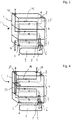
- the FIG. 1 shows a condenser 1, which consists of a Enthitzungs Scheme 3 and a subcooling 4.
- the Enthitzungs Scheme 3 is used for desuperheating a refrigerant and the condensation of the refrigerant from its vapor phase into a liquid phase.
- a coolant which also flows through the Enthitzungs Scheme 3.
- a subcooling section 4 is connected at the top of the decarburization section 3.
- the completely liquid refrigerant is further cooled below the condensation temperature by a further thermal exchange with a coolant.
- a collector 2 is arranged, which is flowed through by the refrigerant.
- the task of the collector 2 is to store, filter and dry the refrigerant.
- the collector 2 has at its fluid outlet 12 a tube 5, which is guided through the Enthitzungs Scheme 3 and is in the subcooling 4 with the flow channel 25 of the refrigerant in fluid communication.
- the fluid inlet 6 of the collector 2 is in turn in fluid communication with the flow channel 25 of the refrigerant in the decompression region 3.
- the collector 2 After flowing through the collector 2, the refrigerant is passed completely into the subcooling region 4.
- the collector 2 thus represents the passage of fluid from the decompression area 3 into the subcooling area 4.
- openings 8, 9, 10 are arranged. These can represent fluid inlets as well as fluid outlets, depending on the design of the inner flow channels. Also shown at the lower end of the disk stack 11 is an opening 7, which may also be a fluid inlet or a fluid outlet, depending on the design of the inner flow channels.
- flow channels 25, 26 are shown for a refrigerant and a coolant.
- the refrigerant flows through the arranged at the lower end portion of the disk stack 11 fluid inlet 7 in the Enthitzungs Scheme 3 of the condenser 1. There it flows through the channels formed by the disc elements, which are associated with the flow channel 25 of the refrigerant.
- the refrigerant flows through the fluid inlet 6 into the collector 2 into it. There it flows through the collector 2 for the purpose of storage, filtration and drying and then flows through the fluid outlet 12 through the tube 5 into the subcooling region 4 of the condenser 1. After flowing through the subcooling region 4, the refrigerant flows through the fluid outlet 8 at the upper end region the capacitor 1 addition.
- the coolant flows through the fluid inlet 9 at the upper end region of the condenser 1 into the subcooling region 4.
- the coolant flows through the individual channels of the subcooling region 4 and of the de-icing region 3 in parallel.
- the coolant flows through inner openings from top to bottom through the disk stack 11 and is distributed over the width of the capacitor 1.
- the coolant After the coolant has flowed over the entire width of the capacitor 1, it then flows through a plurality of openings in the disk elements of down to the top through the fluid outlet 10 from the condenser 1.
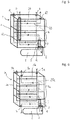
- FIG. 2 shows a similar structure, as it already in the FIG. 1 was presented.
- the flow channel 25 of the refrigerant is analogous to FIG. 1 through the condenser 1 of FIG. 2 arranged. Deviating from FIG. 1 the coolant flows in FIG. 2 now no longer in parallel through the channels of the condenser 1, but flows through the condenser 1 as well as the refrigerant in series.
- the coolant flows through the fluid inlet 30 at the upper region of the condenser 1 into the subcooling region 4. There it is distributed over the width of the condenser 1 and flows via an inner opening down into another channel of the subcooling region 4. There, the coolant spreads again over the entire width before it flows through a further opening down into the Enthitzungs Scheme 3. Finally, after a redistribution over the width of the condenser 1, the coolant flows out of the condenser 1 through the fluid outlet 31 at the lower end region.
- the flow channel 32 of the coolant extends in the FIG. 2 as well as the flow channel 25 of the refrigerant in series through the individual channels in the interior of the condenser 1.
- the refrigerant flow over the entire condenser 1 is in countercurrent to the coolant flow.
- FIG. 3 shows a capacitor 1 analogous to Figures 1 and 2
- the refrigerant flow channel 25 is analogous to Figures 1 and 2 executed.
- the flow channel 42 of the coolant is disposed within the capacitor 1, that both arise areas that are traversed in parallel, as well as areas that are flowed through serially.
- the coolant flows through the fluid inlet 40 into the subcooling region 4 of the condenser 1. There it is distributed over both the width of the capacitor 1, as well as down through inner openings within the subcooling 4. The subcooling 4 is thereby completely flows through in parallel. The coolant then flows through openings from the subcooling region 4 into the desuperheating region 3. From there, the coolant flows out of the condenser 1 via the fluid outlet 41.
- the Enthitzungs Scheme 3 is only flows through serially.
- the condenser 1 is partially flowed through in parallel and partially in series by the coolant. This results in areas in which the refrigerant flows in countercurrent with the refrigerant and areas in which the refrigerant flows with the refrigerant in the DC.
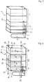
- FIG. 4 also shows a capacitor 1 analogous to the embodiments of FIGS. 1 to 3 ,
- the flow channel 25 of the refrigerant is unchanged from the FIGS. 1 to 3 , Notwithstanding the preceding figures, the coolant is now passed completely in series through the condenser 1.
- the coolant flows through the fluid inlet 50 into the condenser 1 and out of the condenser 1 via the fluid outlet 51.
- Fluid inlet 50 and fluid outlet 51 lie in this case at a common end region of the condenser 1.
- the coolant flows into the subcooling region 4 and is distributed over the width of the condenser 1. It then flows through openings into an underlying part of the subcooling region 4 and likewise distributes itself again over the entire width of the condenser. It then passes through openings in the interior of the condenser 1 in the Enthitzungs Scheme 3. After being distributed across the width of the condenser 1, the coolant flows out of the condenser 1 through the tube 53 via the fluid outlet 51.
- the tube 53 is in fluid communication with one of the channels of the second flow channel 52. Through the pipe 53, the coolant can be led out of the Enthitzungs Scheme 3 through the entire sub-cooling region 4 from the condenser 1, without it can come to a thorough mixing of the refrigerant with the refrigerant.
- the coolant thus flows completely serially through the regions 3 and 4 of the condenser 1.
- the coolant flowing in the flow channel 52 therefore flows countercurrently to the refrigerant in the flow channel 25 at all times.
- FIG. 5 shows a condenser 1.
- the course and orientation of the coolant channel 26 correspond to that in FIG. 1 already shown course.
- the course of the refrigerant channel 60 corresponds in many parts also the course of the flow channel 25 of FIG. 1 ,
- the fluid inlet 61 is now likewise arranged at the upper end region of the condenser 1, as is the fluid outlet 62.
- the condenser 1 has a tube 63 which connects a channel of the de-icing area 3 with the fluid inlet 61.
- the refrigerant therefore flows through the pipe 63 into the Enthitzungs Scheme 3 and from there as already described in the preceding figures serially through the individual channels of the first flow channel in the Enthitzungs Scheme 3 and in the subcooling. 4
- FIG. 6 shows a further view of a capacitor 1a, as in the previous FIGS. 1 to 5 .
- the condenser 1a now has a further subcooling path.
- the subcooling area 4a is thus larger and has more channels than the subcooling area 4 of the previous ones FIGS. 1 to 5 ,
- the flow guide of the first flow passage 25a, through which the refrigerant flows, is completely serial.
- the flow guide of the second flow channel 26a is completely parallel.
- the positioning of the fluid outlet 8a is compared to the arrangement of Fluid outlet 8 of FIG. 1 changed.
- the fluid outlet 8a is arranged, in contrast to FIG. 1, on the opposite side of the condenser 1a.
- the fluid inlet 7 and the fluid outlet 8a are in common alignment.
- the number of channels associated with the first flow channel 25a and the second flow channel 26a depends mainly on the number of disk elements used in the disk stack 11a. There is always a higher number or a lower number predictable.
- the embodiments shown here have no limiting character in this regard.
- FIG. 7 shows an embodiment of a capacitor 70, wherein the subcooling region 71 is represented by two cuboidal elements.
- the Enthitzungs Society 72 is different from the versions of FIGS. 1 to 6 represented by 3 cuboidal elements.
- An increase or decrease in the number of cuboid elements can be achieved by changing the number of disk elements in the disk stack 73.
- FIG. 8 shows a capacitor 80 with a Enthitzungs Scheme 81 at the lower end of the capacitor 80 and two overlying subcooling regions 82.
- the capacitor 80 is substantially formed by the disk stack 93.
- Both the subcooling region 82 and the de-icing region 81 are flowed through in parallel by the coolant.
- Both the fluid inlet 83 and the fluid outlet 84 of the second flow channel 85 are arranged at the lower end region of the condenser 80.
- the fluid inlet 86 of the first flow channel 87 is arranged at the lower end region.
- the flow through the Enthitzungs Schemes 81 and the subcooling region 82 with the refrigerant is done serially similar to that in the illustrations of FIGS. 1 to 4 ,
- This cuboidal element forms an internal heat exchanger 88.
- the inner heat exchanger 88 has a third flow channel 89. At the same time, the refrigerant from the flow channel 87 is guided into the inner heat exchanger 88. Between the fluid of the third flow channel 89 and the refrigerant of the first flow channel 87, a heat transfer in the internal heat exchanger 88 can take place.
- the third flow channel 89 can be flowed through either by refrigerant or by a coolant. As with the other areas of the capacitors shown, and the inner heat exchanger 88 can be flowed through in DC and / or in countercurrent. By flowing in countercurrent, a higher heat transfer between the two fluid streams can be achieved.
- both the fluid inlet 90 and the fluid outlet 91 of the third flow channel 89 are arranged.
- the fluid outlet 92 of the first flow channel 87 is arranged.
- FIGS. 1 to 8 shown positions of the fluid inlets or fluid outlets are each exemplary.
- different orientations, such as on the side of the capacitor are as predictable as the arrangement of a fluid inlet or fluid outlet in a central region of the capacitors.
- the capacitors 1, 1a, 70, 80 are optionally to be produced from a combination of desuperheating region 3, 72, 81, subcooling region 4, 71, 82 and internal heat exchanger 88.
- Optimal configurations can be created depending on the application, all of which follow a simple structure of individual disk elements and are thus very flexible in their construction.
- FIGS. 1 to 8 shown pipes 5, 53, 63, 77 are also inexpensive to produce and are introduced in the simplest case in the disk stacks 11, 11a, 73, 92, thereby leading through inner openings of the disk elements.
- this is done in an early part of the production process, so that the disc elements with the individual tubes 5, 53, 63, 77 can be soldered in one operation.
- the tubes 5, 53, 63, 77 in particular with the openings, which have passages, soldered.
- FIG. 9 shows a sectional view of a capacitor 100 according to the invention.
- the connection region is shown, to which a collector, not shown, is connected via a flange 102 to the disk stack of the capacitor 100.
- the flange 102 has an inlet 104 and a drain 103. Via this, a fluid from the condenser 100 can drain into a collector or run back from the collector into the condenser 100.
- the outlet 103 opens into a tube 101, which itself opens into a flow channel 107.
- the flow channel 107 is one of the channels, which results between, for example, two stacked disk elements 105 and 106.
- a detailed view of the connection of the tube 101 to the disc element 105 is shown in the following FIG. 10 shown.
- a fluid can flow around the tube 101 and further up into an area below the disc element 105.
- the exact design of the channels is also in the FIG. 10 shown.
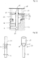
- FIG. 10 shows a detailed view of the arrangement of the tube 101, as it is already in FIG. 9 was shown. It can be seen in FIG. 10 in particular, how the tube 101 is inserted into a drain 103 of the flange 102.
- the drain 103 is formed by a horizontally extending bore within the flange 102.
- the tube 101 is inserted via a vertically opening from the top of the bore 103 of the drain hole.
- the inlet 104 also opens into a bore within the flange 102.
- the larger diameter bore into which the inlet 104 opens is concentric with the bore, which opens into the drain 103 aligned.
- the tube 101 is thus flowed around with the fluid which flows along the inlet 104, while it flows through with the fluid which flows to the outlet 103. There is no fluid communication of the fluid flow outside the tube 101 with the fluid flow within the tube 101.
- the tube 101 has an at least partially circumferential flange 108 in its upper end region.
- This flange 108 is in FIG. 10 produced by a compression and a resulting material doubling of the tube 101.
- the flange 108 abuts against the underside of the disk element 105.
- the disc member 105 further includes a passage 112 formed around the opening through which the tube 101 is inserted. Above the disk element 105, a flow channel 107 is formed, below the disk element 105, a flow channel 109 is formed.
- multiple numbers of flow channels can also be provided above and below the disk element 105.
- the presentation of the FIG. 10 is exemplary.
- the tube 101 is primarily connected to the disc element 105. This can be achieved for example by a gluing process or a soldering process.
- the flange 102 is fastened to a lower disk element 110 by means of connecting elements 111.
- the disk element 110 has an opening which has a downward passage.
- the connecting means 111 are in the FIG. 10 formed over material extensions of the flange 102, which engage behind the passage of the disc member 110 and thus prevent slipping out of the flange 102 from the opening of the disc member 110.
- Between the flange 102 and the disk element 110 may also be provided, for example, an adhesive connection or a solder joint for permanent connection.
- FIG. 11 also shows a connection of a flange 120 to a capacitor, which is formed from a plurality of disk elements 128, 129 and 132.
- the structure of the flange 120 corresponds substantially to the already shown flange 102.
- the flange 120 is also connected to a passage of an opening of the lower disc member 132 to the capacitor again.
- the tube 125 has a bevel on both the upper end portion 126 and the lower end portion 127. This chamfer is achieved by a cut, which was generated in a plane which is at a predeterminable angle to the central axis of the tube 125. By the tapered end portions 126, 127, the tube has a sweep at both ends.
- the tube 125 is supported by the tip on the disc element 128 lying on top.
- the disk element 128 forms a deflection disk for the flow channel 123 shown.
- the lower disk element 129 forms a separating disk for the flow channel 123.
- the tube 125 thus provides fluid communication between the drain 121 and the flow channel 123. Due to the sweep, the tube 125 can abut an area with an end region 126 and thereby position the tube 125 as well as a suitable fluid transfer surface from the tube Form 125 in the flow channel or from a flow channel in the tube 125.
- the tube 125 is also connected to a passage 131 which is formed around the opening 130 of the disc member 129 with the disc member 129.
- the tube 125 also has a bevelled end region 127. Via this beveled end region, the tube can be supported in the flange 120 and at the same time represent a suitable flow cross section for the passage of fluid out of the drain 121 into the tube 125.
- FIG. 12 shows two embodiments of a tube 140 and 150.
- the pipe 140 is shown in the left part of FIG. 12 . This has at the bottom of a peripheral flange 143, with which it can be supported against disc elements or a flange.
- the tube 140 has a flexible region 141.
- This flexible region 141 is generated by a concertina-like design of the tube 140.
- the accordion-like region has a plurality of material folds 142.
- the tube 140 can accommodate both compressions and strains, particularly in the axial direction, particularly preferred.
- the material folds 142 are moved towards each other, in the case of stretching they are pulled apart.
- the possible length compensation which can be achieved via the tube 140, may vary in size.
- the right part of the FIG. 12 shows an alternative design of a pipe 150.
- the pipe 150 is formed by a first pipe section 151 and a second pipe section 152.
- the pipe sections 151, 152 are inserted into one another in such a way that they are movable relative to each other.
- the pipe sections 151, 152 are so fluid-tight to one another that no unwanted mixing between a fluid flowing around the pipe 150 and a fluid flowing through the pipe 150 is produced.
- the second pipe section 152 has a funnel-shaped widening cross section in the axial direction upwards.
- the first pipe section 151 has a funnel-shaped, tapered cross-section viewed in the axial direction downward.
- the inner diameter of the first pipe section 151 is selected such that it is greater than the outer diameter of the second pipe section 152. In this way, the two pipe sections 151, 152 can be moved relative to each other.
- the design of the funnel-shaped regions of the pipe section 151 or of the pipe section 152 simultaneously realizes a stop which defines a limitation of the maximum possible relative movement of the pipe sections 151, 152 relative to one another.
- the configuration of the tubes 140 and 150 of the FIG. 12 is exemplary.
- the tube 140 or 150 can advantageously metallic materials, but also more flexible Materials such as plastics or elastomers are used.
- the embodiments of the FIG. 12 have no limiting character with regard to the design of the pipe.
- FIGS. 1 to 8 Illustrations of a capacitor shown also have exemplary character and have no limiting effect. They can be combined with each other and clarify the idea of the invention.
- FIGS. 9 to 12 shown representation of the connection of a pipe or a flange to a capacitor is also exemplary.
- the various tubes shown the FIGS. 9 to 12 with the different capacitors of the FIGS. 1 to 8 can be combined arbitrarily. It can in the FIGS. 9 to 12 shown pipes are used both for the connection of the collector and for the connection of channels with fluid inlets and fluid outlets in the remaining area of the capacitors.
Landscapes
- Engineering & Computer Science (AREA)
- Physics & Mathematics (AREA)
- Mechanical Engineering (AREA)
- Thermal Sciences (AREA)
- General Engineering & Computer Science (AREA)
- Air-Conditioning For Vehicles (AREA)
- Heat-Exchange Devices With Radiators And Conduit Assemblies (AREA)
- Details Of Heat-Exchange And Heat-Transfer (AREA)
- Fixed Capacitors And Capacitor Manufacturing Machines (AREA)
Description
- Die Erfindung betrifft einen Kondensator in Stapelscheibenbauweise, mit einem ersten Strömungskanal für ein Kältemittel und mit einem zweiten Strömungskanal für ein Kühlmittel gemäß dem Anspruch 1.
- In Kältemittelkreisläufen von Klimaanlagen für Kraftfahrzeuge werden Kondensatoren eingesetzt, um das Kältemittel auf die Kondensationstemperatur abzukühlen und zu kondensieren. Kondensatoren können dabei einen Sammler aufweisen, welcher ein Kältemittelvolumen vorhält. Über dieses Kältemittelvolumen können Volumenschwankungen im Kältemittelkreislauf ausgeglichen werden.
- Oftmals sind in dem Sammler zusätzliche Mittel zur Trocknung und/oder Filterung des Kältemittels vorgesehen. Der Sammler ist im Regelfall am Kondensator angeordnet. Er wird von dem Kältemittel durchströmt, welches bereits einen Teil des Kondensators durchströmt hat. Nach dem Durchströmen des Sammlers wird das Kältemittel in den Kondensator zurückgeleitet und in einer Unterkühlungsstrecke unter die Kondensationstemperatur unterkühlt.
- Bei konventionellen Kondensatoren in Rippe-Rohr-Bauweise wird das Kältemittel hierfür aus einem der seitlich des Rohr-Rippenblocks angeordneten Sammelrohre aus dem Kondensator hinausgeleitet und in den Sammler eingeleitet.
Bei Kondensatoren in Stapelscheibenbauweise kann es vorgesehen sein, dass der Sammler als zusätzliche Schicht in Form von Scheibenelementen an den Scheibenstapel angefügt wird.
Außerdem sind im Stand der Technik Lösungen bekannt, bei denen das Kältemittel über eine spezielle Verteilerplatte aus dem in Stapelscheibenbauweise gebauten Kondensator hinausgeleitet wird und einem externen Sammler zugeführt wird. Nach dem Durchströmen des Sammlers wird das Kältemittel wieder in den Kondensator zurückgeführt.US 2009/071189 A1 offenbart einen Kondensator gemäß dem Oberbegriff von Anspruch 1. Nachteilig an den Lösungen aus dem Stand der Technik ist insbesondere, dass eine Integration von Kondensatoren, Sammlern und Unterkühlern mit hohem Aufwand verbunden ist. Die aus dem Stand der Technik bekannten Kondensatoren zeichnen sich durch einen komplexen Aufbau und einen erhöhten Fertigungsaufwand aus. Dadurch entstehen Mehrkosten, die den Einsatz solcher Kondensatoren unattraktiv machen. - Daher ist es die Aufgabe der vorliegenden Erfindung einen Kondensator bereitzustellen, der geeignet ist ein Kältemittel zu kondensieren, es zu bevorraten und weiterhin zu unterkühlen, wobei der Kondensator durch einen einfachen Aufbau und eine kompakte Bauweise gekennzeichnet ist und kostengünstig herzustellen ist.
Die Aufgabe der vorliegenden Erfindung wird durch einen Kondensator in Stapelscheibenbauweise mit den Merkmalen des Anspruchs 1 gelöst. - Die r Erfindung betrifft einen Kondensator in Stapelscheibenbauweise, mit einem ersten Strömungskanal für ein Kältemittel und mit einem zweiten Strömungskanal für ein Kühlmittel, wobei eine Mehrzahl von Scheibenelementen vorgesehen ist, die aufeinandergestapelt zueinander benachbarte Kanäle zwischen den Scheibenelementen ausbilden, wobei eine erste Anzahl der Kanäle dem ersten Strömungskanal zugeordnet ist und eine zweite Anzahl der Kanäle dem zweiten Strömungskanal zugeordnet ist, wobei der erste Strömungskanal einen ersten Bereich zur Enthitzung und Kondensation des dampfförmigen Kältemittels aufweist und einen zweiten Bereich zur Unterkühlung des kondensierten Kältemittels aufweist, mit einem Sammler zur Bevorratung eines Kältemittels, wobei ein Kältemittelübertritt aus dem ersten Bereich in den zweiten Bereich durch den Sammler führt, wobei der Sammler über ein erstes Anschlusselement, welches einen ersten Fluidanschluss des Sammlers bildet, mit dem ersten Bereich in Fluidkommunikation steht, wobei der Sammler über ein zweites Anschlusselement, welches einen zweiten Fluidanschluss des Sammlers bildet, mit dem zweiten Bereich in Fluidkommunikation steht, wobei das erste Anschlusselement und/oder das zweite Anschlusselement durch ein Rohr gebildet sind, welches durch Öffnungen in den Scheibenelementen durch eine Anzahl von Scheibenelementen greift.
Der Aufbau eines Kondensators in Stapeischeibenbauweise ist besonders einfach und kostengünstig zu realisieren. Im Regelfall können eine Vielzahl identischer Scheibenelemente für den Aufbau verwendet werden. Lediglich die äußeren Begrenzungsplatten des Scheibenstapels oder Scheibenelemente im Inneren des Scheibenstapels, welche zusätzliche Funktionalitäten aufweisen, wie etwa das Blockieren oder Umlenken eines Strömungskanals, weisen eine abweichende Gestaltung auf.
Die Aufteilung des Strömungskanals, welcher das Kältemittel führt in einen ersten Bereich, welcher der Enthitzung und der Kondensation des Kältemittels in seiner dampfförmigen Phase dient, und einen zweiten Bereich, welcher der Unterkühlung des kondensierten Kältemittels dient, führt dazu, dass am Ende des Kondensators stets vollständig unterkühltes Kältemittel vorliegt. - Um das Kältemittelvolumen im Kältemittelkreislauf konstant zu halten und das Kältemittel zusätzlich zu Trocknen und/oder zu Filtrieren, ist es vorteilhaft einen Sammler in den Kältemittelkreislauf zu integrieren. Dieser ist vorteilhafterweise an einer Stelle in den Strömungskanal des Kältemittels integriert, an welcher das Kältemittel bereits vollständig kondensiert ist, jedoch noch nicht unterkühlt ist.
- Durch die Verwendung eines Rohres zum Anschluss eines Sammlers an den ersten Strömungskanal, kann der Kondensator trotz einer Anordnung des Sammlers außerhalb des Kondensators durch einen Scheibenstapel gebildet sein, der überwiegend aus identischen Scheibenelementen besteht.
- Das Rohr wird dabei durch eine Reihe von benachbart zueinander liegenden Scheibenelementen geführt. Hierbei wird das Rohr bevorzugt durch die Öffnungen der Scheibenelemente geführt. Das Rohr wird dabei derart in den Scheibenstapel eingeführt, dass es in einen der Kanäle mündet, der dem gewünschten Strömungskanal zugeordnet ist. Im vorliegenden Fall einem Kanal des ersten Strömungskanals.
- Auch ist es zu bevorzugen, wenn das erste Anschlusselement als Rohr ausgebildet ist und das Rohr vom zweiten Bereich durch den ersten Bereich zu einem Fluidanschluss des Sammlers führt, wobei das Rohr mit dem zweiten Bereich des ersten Strömungskanals und dem Sammler in Fluidkommunikation steht.
- Um den Sammler an der für den gesamten Arbeitsprozess des Kondensators günstigsten Stelle zu integrieren, ist es besonders vorteilhaft, wenn der Sammler direkt an den Enthitzungsbereich und den Kondensationsbereich angeschlossen ist. Dieser erste Bereich des Kondensators liegt in Strömungsrichtung des Kältemittels betrachtet vor dem zweiten Bereich, in welchem die Unterkühlung stattfindet.
- Um das gesamte Kältemittel aus dem zweiten Bereich des ersten Strömungskanals in den Sammler hinein oder aus diesem heraus zu leiten, ist das Rohr so dimensioniert, dass es durch alle Scheibenelemente des ersten Bereiches hindurchgreift und in einen Kanal des zweiten Bereichs mündet. Auf diese Weise wird das Kältemittel am ersten Bereich vorbei direkt in den Sammler oder aus dem Sammler heraus geleitet.
- Weiterhin ist es zu bevorzugen, wenn zumindest eines der Rohre eine Verjüngung und/oder einen Absatz und/oder einen zumindest teilweise umlaufenden Flansch und/oder eine Aufweitung aufweist, worüber es an einem der Scheibenelemente abstützbar und im Kondensator fixierbar ist.
- Ein Flansch kann dabei etwa durch Stauchen erzeugt werden, alternativ kann der Flansch auch als gesondertes Bauteil ausgeführt sein, welches an ein Rohr angefügt wird. Der Flansch dient dabei der Abstützung gegenüber einem oder mehreren der Scheibenelemente und trägt zu einer besseren Abdichtung bei.
- Alternativ kann an einem der Rohre eine Verjüngung vorgesehen sein, mit welcher das Rohr in eine Öffnung einsetzbar ist. Eine Verjüngung kann dabei beispielsweise durch eine Pressung erzeugt werden oder durch eine spanende Bearbeitung. Eine Aufweitung kann beispielsweise durch ein Innenhochdruckverfahren erzeugt werden.
- Über eines oder mehrere dieser Elemente kann ein Rohr besonders vorteilhaft an den Scheibenelementen des Kondensators abgestützt werden und im Kondensator fixiert werden. Die oben beschriebenen Elemente können dabei insbesondere als Anschlag dienen.
- Auch ist es zweckmäßig, wenn zumindest eines der Scheibenelemente als Trennscheibe und/oder eines der Scheibenelemente als Umlenkscheibe ausgebildet ist.
- Eine Trennscheibe unterscheidet sich dabei im Wesentlichen dadurch von einer Umlenkscheibe, dass die Öffnungen in dem jeweiligen Scheibenelement, über welche der zwischen den Scheiben ausgebildete Kanal mit einem benachbarten Kanal in Fluidkommunikation steht, an unterschiedlichen Stellen vorgesehen sind. Ansonsten können die beiden Scheibenelemente einen sehr ähnlichen oder identischen Aufbau aufweisen. Die unterschiedliche Anordnung der Öffnungen kann dabei beispielsweise über ein seitenverkehrtes Aufeinanderlegen der Scheibenelemente erreicht werden.
- Eine Umlenkscheibe zeichnet sich dabei insbesondere dadurch aus, dass sie gegenüber der Öffnung der benachbarten Trennscheibe, welche ein Einströmen eines Fluids in einen der Strömungskanäle erlaubt, keine Öffnung vorsieht und damit das einströmende Fluid innerhalb des Kanals um- bzw. ablenkt.
- Darüber hinaus ist es vorteilhaft, wenn das Rohr im Kondensator an einer Umlenkscheibe abgestützt ist.
- Durch das Abstützen des Rohres an einer Umlenkscheibe ist die Bewegung des Rohres in den Kondensator hinein, insbesondere während des Montagevorgangs, schon durch den Anschlag des Rohres an der Umlenkscheibe begrenzt. Dies erleichtert die Montage und erhöht die Stabilität des Kondensators.
- Weiterhin ist es zu bevorzugen, wenn das Rohr radiale und/oder axiale Öffnungen aufweist.
- Falls das Rohr an einer Umlenkscheibe anliegt, ist es besonders vorteilhaft, wenn radiale Öffnungen vorgesehen sind, durch welche ein Fluid aus dem Rohr hinaus oder in das Rohr hinein strömen kann. Die radialen Öffnungen können beispielsweise durch Bohrungen, Schlitze oder anderweitige Ausnehmungen gebildet sein. Die Öffnungen sind vorteilhafterweise an einem der Endbereiche des Rohres angeordnet, um ein definiertes Überströmen vom Rohr in einen oder mehrere der Strömungskanäle zu erzeugen.
- Auch ist es vorteilhaft, wenn das Rohr an einem der äußeren Scheibenelemente des zweiten Bereichs abgestützt ist.
- Mit einem äußeren Scheibenelement ist hier insbesondere eines der Scheibenelemente gemeint, welches den zweiten Bereich, der aus einem Stapel von mehreren Scheibenelementen gebildet ist, zu einem benachbarten Bereich abschließt.
- Gemäß einer besonders günstigen Weiterbildung der Erfindung, kann es vorgesehen sein, dass am Fluideinlass und/oder am Fluidauslass des ersten Strömungskanals ein zweites Rohr vorgesehen ist, welches mit einem anderen Kanal des ersten Strömungskanals in Fluidkommunikation steht.
- Außerdem ist es zweckmäßig, wenn am Fluideinlass und/oder am Fluidauslass des zweiten Strömungskanals ein drittes Rohr vorgesehen ist, welches mit einem anderen Kanal des zweiten Strömungskanals in Fluidkommunikation steht.
- Durch die Verbindung des Fluideinlasses oder des Fluidauslasses des jeweils ersten Strömungskanals oder des zweiten Strömungskanals kann das durch den entsprechenden Strömungskanal fließende Fluid an benachbarten Kanälen vorbeigeführt werden und damit in oder aus einem vorgegebenen Kanal eingeleitet oder ausgeleitet werden. Es kann dadurch eine Gestaltung des Kondensators erreicht werden, welche sowohl den Fluideinlass als auch den Fluidauslass des jeweiligen Strömungskanals an einem gemeinsamen Endbereich aufweist.
- Es ist dabei vorteilhaft, wenn der andere Kanal einer der letzten Kanäle des jeweiligen Strömungskanals ist, welcher der Einführseite des Rohres in dem Scheibenstapel im Wesentlichen gegenüber liegt.
- Auf diese Weise kann erreicht werden, dass das Kältemittel oder das Kühlmittel durch den gesamten Kondensator oder den innerhalb des Kondensators vorgesehenen Strömungsweg strömt, bevor es durch das Rohr wieder durch den ganzen Kondensator zurück strömt und am selben Endbereich des Scheibenstapels, an welchem es in den Scheibenstapel eingeströmt ist, auch wieder ausströmt.
- Weiterhin ist es zu bevorzugen, wenn die Scheibenelemente Öffnungen mit oder ohne Durchzug aufweisen.
- Wenn zueinander direkt benachbarte Scheibenelemente einander gegenüberliegende Öffnungen mit Durchzügen aufweisen, fließt das Fluid direkt in den übernächsten Kanal des Scheibenstapels, da durch die beiden sich gegenüberliegenden Durchzüge eine Strömungspassage gebildet wird.
- Hierdurch wird erreicht, dass ein Wechsel zwischen Kanälen, welche zum ersten Strömungskanal zählen, und Kanälen, welche zum zweiten Strömungskanal zählen, im Scheibenstapel erreicht wird. Dabei kann eine gleichmäßige Verteilung erzeugt werden, so dass auf einen Kanal des ersten Strömungskanals immer ein Kanal des zweiten Strömungskanals folgt. Auch davon abweichende Verteilungen können mit dieser Methode erzeugt werden.
- Auch ist es vorteilhaft, wenn das zumindest eine Rohr durch die Öffnungen in den Scheibenelementen geführt ist und mit zumindest einem Teil der Scheibenelemente, insbesondere den Durchzügen, verlötet ist.
- Durch ein Einstecken der Rohre in die Öffnungen und ein Verlöten der Rohre mit den Scheibenelementen und insbesondere mit den Durchzügen, wird eine kompakte Baueinheit erreicht, die sich durch eine hohe Festigkeit auszeichnet. Vorteilhafterweise können die Rohre hier in einem einzigen Arbeitsschritt mit dem Scheibenstapel verlötet werden. Dies ist insbesondere hinsichtlich eines optimierten Produktionsprozesses besonders vorteilhaft.
- Weiterhin kann es besonders vorteilhaft sein, wenn zumindest eines der Rohre einen zumindest teilweise umlaufenden Flansch aufweist, worüber es an einem der Scheibenelemente abstützbar ist.
- Ein Flansch kann dabei etwa durch Stauchen erzeugt werden, alternativ kann der Flansch auch als gesondertes Bauteil ausgeführt sein, welches an ein Rohr angefügt wird. Der Flansch dient dabei der Abstützung gegenüber einem oder mehreren der Scheibenelemente und trägt zu einer besseren Abdichtung bei.
- Ein bevorzugtes Ausführungsbeispiel ist dadurch gekennzeichnet, dass zumindest eines der Rohre an einem Endbereich oder an beiden Endbereichen abgeschrägt ist.
- Ein abgeschrägtes Rohr ist vorteilhafterweise durch einen Schnitt durch das Rohr entlang einer Ebene, welche in einem vorgebbaren Winkel zur Mittelachse des Rohres steht, erzeugt. Dadurch ergibt sich eine Pfeilung des Rohres. Über ein derart abgeschrägtes Rohr kann erreicht werden, dass sich das Rohr mit der entstehenden Spitze an einer Anschlagfläche, insbesondere an einem Scheibenelement, innerhalb des Kondensators abstützen kann und gleichzeitig ein Fluid in das Rohr einströmen kann.
- Auch ist es zu bevorzugen, wenn zumindest eines der Rohre einen flexiblen Bereich aufweist, wobei das Rohr durch den flexiblen Bereich in axialer Richtung stauchbar und/oder dehnbar ist.
- Über einen flexiblen Bereich, der die Kompensation einer Stauchung oder Dehnung ermöglicht, kann eine Längenveränderung des Kondensators kompensiert werden. Insbesondere während des Lötprozesses tritt eine sogenannte Setzung im Kondensator auf. Diese Setzung ist durch eine Relativbewegung der Scheibenelemente zueinander während des Lötvorgangs verursacht. Ein flexibler Bereich in den Rohren kann somit das Auftreten von Spannungen innerhalb des Kondensators verhindern. Der flexible Bereich kann dabei sowohl Stauchungen infolge von Setzungsvorgängen aufnehmen als auch Dehnungen infolge von anderen mechanischen oder thermischen Einflüssen.
- In einer besonders günstigen Ausgestaltung der Erfindung ist es außerdem vorgesehen, dass der flexible Bereich durch eine ziehharmonikaartige Gestaltung des Rohres gebildet ist.
- Eine ziehharmonikaartige Gestaltung des flexiblen Bereichs ermöglicht es auf besonders einfach Weise Stauchungen und/oder Dehnungen aufzunehmen. Der flexible Bereich ist dabei durch gefaltete Materialbereiche gebildet, die im Falle einer Stauchung aufeinander zu bewegt werden und im Falle einer Dehnung voneinander weg bewegt werden. Das Rohr kann dabei derart gestaltet sein, dass eine Stauchung oder Dehnung einmalig oder mehrmalig aufgenommen werden kann.
- In einer alternativen Ausgestaltung der Erfindung kann es vorgesehen sein, dass der flexible Bereich aus einem elastischen Material, wie beispielsweise Kunststoff oder Gummi, gebildet ist, wobei eine Stauchung oder Dehnung des Rohres in axialer Richtung und/oder in radialer Richtung reversibel ist.
- Eine Ausführung der flexiblen Stelle aus einem Material, wie etwa Kunststoff oder Gummi ist insbesondere vorteilhaft, um eine reversible Verformung des Rohres zu ermöglichen. Kunststoffe und Gummi weisen dabei eine wesentlich höhere Formveränderungsfähigkeit auf als metallische Werkstoffe.
- Weiterhin ist es zu bevorzugen, wenn zumindest eines der Rohre aus einer Mehrzahl von Rohrabschnitten gebildet ist, wobei die Rohrabschnitte fluiddicht miteinander verbunden sind.
- Ein Rohr, das aus einer Mehrzahl von Rohrabschnitten gebildet ist, kann besonders vorteilhaft einen Längenausgleich darstellen. Dies kann erreicht werden, indem die Rohrabschnitte eine Relativbewegung zueinander durchführen. Vorteilhafterweise sind die Rohrabschnitte dabei ineinander gesteckt, wobei ein Rohrabschnitt einen geringeren Außendurchmesser aufweist als der Innendurchmesser des jeweils anderen Rohrabschnitts. Eine fluiddichte Verbindung der jeweiligen Rohrabschnitte miteinander ist dabei besonders vorteilhaft, um keine ungewollte Vermischung der Fluidströme innerhalb des Kondensators zu erzeugen.
- Ein solcher Rohraufbau ist besonders dazu geeignet, um die Längenveränderungen auszugleichen, die beim Verlöten des Scheibenstapels entstehen. Insbesondere durch die Wärmeeinwirkung kann es beim Löten zu sogenannten Setzvorgängen kommen, wodurch die einzelnen Scheibenelemente zumindest teilweise ineinander gleiten. Diese Längenveränderung kann dabei vorteilhafterweise durch ein mehrteiliges Rohr ausgeglichen werden.
- Nach Abschluss des Lötvorgangs, sind die Rohrabschnitte dann vorteilhafterweise ebenfalls miteinander verlötet, so dass eine Relativbewegung der Abschnitte zueinander verhindert ist. Auf diese Weise ist auch die Fluiddichtheit des Rohres auf einfache Weise erzeugbar.
- Auch kann es zweckmäßig sein, wenn sich ein erster Rohrabschnitt in axialer Richtung trichterförmig verjüngt und sich der zweite Rohrabschnitt in axialer Richtung trichterförmig erweitert, wobei die beiden Rohrabschnitte derart ineinander eingesetzt sind, dass die Relativbewegung zwischen dem zweiten Rohrabschnitt und dem ersten Rohrabschnitt durch ein Anschlagen des sich erweiternden Bereichs an dem sich verjüngenden Bereich begrenzt ist.
- Durch eine trichterförmige Ausgestaltung der Rohrabschnitte kann eine Relativbewegung der Rohrabschnitte zueinander ermöglicht werden und gleichzeitig ein Anschlag erzeugt werden, welcher die Relativbewegung begrenzt. Vorteilhafterweise weist dafür der erste Rohrabschnitt einen Innendurchmesser auf, der ausreichend groß ist, damit der zweite Rohrabschnitt innerhalb des ersten Rohrabschnitts bewegt werden kann.
- Darüber hinaus ist es zweckmäßig, wenn das Rohr in einem Anschlusselement aufgenommen ist und mit diesem fluiddicht verbunden ist.
- Ein Anschlusselement kann beispielsweise durch einen Flansch am Kondensator oder am Sammler gebildet sein.
- Weiterhin ist es vorteilhaft, wenn der zweite Bereich eine Mehrzahl von Strömungsstrecken aufweist, welche von dem Kältemittel durchströmbar sind, wobei die Strömungsstrecken jeweils durch einzelne Kanäle des ersten Strömungskanals gebildet sind und/oder durch Teilbereiche einzelner Kanäle des ersten Strömungskanals gebildet sind.
- Eine Mehrzahl von Strömungsstrecken zur Führung des Kältemittels im zweiten Bereich des ersten Strömungskanals ist vorteilhaft, um einen verbesserten Wärmeübertrag zwischen dem Kältemittel und dem Kühlmittel zu erreichen. Dabei können die Strömungsstrecken durch Kanäle, welche zwischen zueinander benachbarten Scheibenelementen ausgebildet sind, gebildet sein oder durch Teilbereiche dieser Kanäle. Hierzu können beispielsweise Trennmittel in den Kanälen vorgesehen sein, wodurch die Kanäle in Teilbereiche unterteilt werden. Je nach fluidischer Verschaltung der Kanäle bzw. der Strömungsstrecken untereinander können die einzelnen Strömungsstrecken parallel oder seriell von dem Kältemittel durchströmt werden. Weiterhin kann eine Strömung des Kältemittels im Gleichstrom und/oder im Gegenstrom mit dem Kühlmittel erreicht werden.
- Auch ist es zu bevorzugen, wenn der zweite Bereich eine Mehrzahl von Kanälen aufweist, wobei zumindest einzelne Kanäle des zweiten Bereichs mit dem zweiten Strömungskanal in thermischen Kontakt stehen, wobei das Kühlmittel und das Kältemittel im Gleichstrom und/oder im Gegenstrom zueinander durch die Kanäle des zweiten Bereichs und den zweiten Strömungskanal strömbar sind.
- Ein Strömen von Kältemittel und Kühlmittel in mehreren zueinander benachbarten Kanälen ist besonders vorteilhaft, um einen möglichst großen Wärmeübertrag realisieren zu können. Dabei kann insbesondere durch eine Gegenstromanordnung ein besonders großer Wärmeübertrag erreicht werden. Auch eine gemischte Anordnung von Passagen im Gegenstrom und Passagen im Gleichstrom oder eine reine Gleichstromanordnung kann vorteilhaft sein.
- In einem weiteren bevorzugten Ausführungsbeispiel kann es vorgesehen sein, dass die den ersten Strömungskanal bildenden Kanäle seriell und/oder parallel von dem Kältemittel durchströmbar sind.
- Durch eine serielle und/oder parallele Durchströmung können Vorteile, insbesondere hinsichtlich des zu realisierenden Wärmeübertrags, erreicht werden. Es können Bereiche erzeugt werden, in denen das Kältemittel im Gleichstrom oder im Gegenstrom zum Kühlmittel durch den ersten Strömungskanal strömt.
- Außerdem kann es vorteilhaft sein, wenn die den zweiten Strömungskanal bildenden Kanäle seriell und/oder parallel von dem Kühlmittel durchströmbar sind.
- Ebenfalls, wie beim ersten Strömungskanal, können Vorteile beim zu erzielenden Wärmeübertrag erreicht werden. Insbesondere durch eine gezielte Beeinflussung der Durchströmungsrichtung des ersten und des zweiten Strömungskanals kann eine durchgehende Durchströmung im Gegenstrom des Kältemittels und des Kühlmittels erreicht werden.
- Zusätzlich kann durch eine Beeinflussung des Durchströmungsprinzips eine vorteilhafte Gestaltung der Fluideinlässe und Fluidauslässe des Kondensators erreicht werden.
- Weiterhin ist es zu bevorzugen, wenn der zweite Strömungskanal seriell durchströmbar ist und ein Fluideinlass und ein Fluidauslass des zweiten Strömungskanals jeweils am gleichen Endbereich des Scheibenstapels angeordnet sind.
- Durch eine Anordnung des Fluideinlasses und des Fluidauslasses am gleichen Endbereich des Scheibenstapels kann der Kondensator besonders kompakt konstruiert werden.
- In einer besonders günstigen Ausgestaltung der Erfindung ist es außerdem vorgesehen, dass der erste Bereich oder der zweite Bereich des ersten Strömungskanals mit einem dritten Strömungskanal einen inneren Wärmeübertrager in Stapelscheibenbauweise bildet, wobei der erste und der dritte Strömungskanal von einem Kältemittel durchströmbar sind.
- Die Unterkühlungsstrecke des zweiten Bereichs wird in einem Ausführungsbeispiel zumindest teilweise durch einen inneren Wärmeübertrager ersetzt. Die Unterkühlung des Kältemittels erfolgt hier nicht durch einen Wärmeübertrag zwischen dem Kältemittel und dem Kühlmittel.
- Durch einen inneren Wärmeübertrager kann die Abkühlung des Kältemittels im Kondensator noch einmal verstärkt werden, was zu einer insgesamt höheren Leistungsfähigkeit des Kondensators führt. In einem inneren Wärmeübertrager strömt dabei Kältemittel in zwei unterschiedlichen Strömungskanälen, die derart ausgerichtet sind, dass ein Wärmeübertrag zwischen den Fluiden in den Strömungskanälen ermöglicht wird. Vorteilhafterweise strömen die Fluide dabei im Gegenstrom zueinander.
- Das Kältemittel, welches in den beiden Strömungskanälen strömt, wird dem inneren Wärmeübertrager dabei aus unterschiedlichen Abschnitten des Kältemittelkreislaufes zugeführt, wodurch eine möglichst große Temperaturdifferenz zwischen den Fluiden in den beiden Strömungskanälen erreicht wird.
- Die Anordnung eines inneren Wärmeübertragers nach dem zweiten Bereich, in welchem die Unterkühlung stattfindet, senkt die Temperatur des Kältemittels noch weiter ab. Es kommt insgesamt zu einer stärkeren Unterkühlung des Kältemittels, als durch die reine Verwendung einer Unterkühlstrecke oder eines inneren Wärmeübertragers.
- Gemäß einem weiteren bevorzugten Ausführungsbeispiel kann es vorgesehen sein, dass der dritte Strömungskanal unabhängig vom ersten Strömungskanal mit einem Kältemittel oder unabhängig vom zweiten Strömungskanal mit einem Kühlmittel versorgbar ist.
- Die unabhängige Versorgung des dritten Strömungskanals mit entweder einem Kühlmittel oder einem Kältemittel ist besonders vorteilhaft, da auf diese Weise eine höhere Temperaturdifferenz zwischen dem dritten Strömungskanal und dem ersten Strömungskanal erzielt werden kann. Dies gilt insbesondere dann, wenn dem dritten Strömungskanal ein zusätzlich abgekühltes Fluid zugeführt wird.
- Weiterhin ist es zu bevorzugen, wenn der Sammler über ein Rohr, welches durch einen Teil des Scheibenstapels führt und den Fluideinlass in den Sammler bildet, nur mit dem zweiten Bereich des ersten Strömungskanals in Fluidkommunikation steht und der Fluidauslass des Sammlers über ein weiteres Rohr gebildet ist, welches durch einen Teil des Scheibenstapels führt und nur mit dem ersten Bereich des ersten Strömungskanal in Fluidkommunikation steht.
- Über diese Anbindung des Sammlers an den ersten und den zweiten Bereich des ersten Strömungskanals mittels Rohren, kann der Sammler außerhalb des Scheibenstapels platziert werden und gleichzeitig der einfache Aufbau des Scheibenstapels durch eine Verwendung von vielen identischen Scheibenelementen erreicht werden.
- Die Rohre sind dabei durch die Scheibenelemente der Bereiche des Scheibenstapels geführt, mit denen sie nicht in Fluidkommunikation stehen sollen, und münden dann in die Kanäle des Scheibenstapels, mit denen sie in Fluidkommunikation stehen.
- Ein weiteres bevorzugtes Ausführungsbeispiel der Erfindung sieht vor, dass der Fluideinlass und/oder der Fluidauslass des inneren Wärmeübertragers durch ein Rohr gebildet sind.
- Die Anbindung des inneren Wärmeübertragers über ein oder zwei Rohre ist deshalb vorteilhaft, weil auf diese Weise die einfache Aufbaustruktur des Scheibenstapels des Kondensators beibehalten werden kann. Das Kältemittel, welches durch den dritten Strömungskanal des inneren Wärmeübertragers strömt, kann durch ein Rohr gezielt in einen Kanal des dritten Strömungskanals geführt werden und auch gezielt aus einem Kanal des dritten Strömungskanals hinausgeleitet werden.
- Außerdem ist es zu bevorzugen, wenn das erste Anschlusselement ein Rohr und das zweite Anschlusselement ein Flansch ist oder umgekehrt.
- Über eine Ausbildung des ersten und zweiten Anschlusselements, wie oben beschrieben, ist eine vorteilhafte Anbindung des Sammlers an den Kondensator zu erreichen. Über einen Flansch lässt sich hierbei insbesondere eine sehr stabile Verbindung erzielen, während das Rohr zu einer gezielten Zuführung des Fluids in den Kondensator genutzt werden kann.
- Gemäß einer weiteren alternativen Ausführung kann es vorgesehen sein, dass der Sammler zur Filterung und/oder Trocknung des Kältemittels ausgebildet ist.
- Neben der Aufgabe der Bevorratung realisiert der Sammler vorteilhafterweise auch die Funktion der Trocknung des Kältemittels über geeignete Mittel zur Trocknung und weiterhin die Filterung des Kältemittels. Auf diese Weise kann dem Kältemittel überschüssige Feuchtigkeit entzogen werden und es weiterhin von Verunreinigungen befreit werden. Die Integration dieser Funktionen in einem einzigen Bauteil ist insbesondere hinsichtlich der Teilevielfalt und der Bauraumausnutzung vorteilhaft.
- Vorteilhafte Weiterbildungen der vorliegenden Erfindung sind in den Unteransprüchen und in der nachfolgenden Figurenbeschreibung beschrieben.
- Im Folgenden wird die Erfindung anhand von Ausführungsbeispielen unter Bezugnahme auf die Zeichnungen detailliert erläutert. In den Zeichnungen zeigen:
- Fig.1
- eine schematische Ansicht eines Kondensators mit einer Darstellung zweier Strömungskanäle, wobei das Kältemittel den Kondensator seriell durchströmt und das Kühlmittel den Kondensator parallel durchströmt,
- Fig. 2
- eine schematische Ansicht eines Kondensators, gemäß der
Figur 1 , wobei das Kältemittel den Kondensator seriell durchströmt und das Kühlmittel den Kondensator seriell durchströmt, - Fig. 3
- eine schematische Ansicht eines Kondensators, gemäß der
Figuren 1 bis 2 , wobei das Kältemittel den Kondensator seriell durchströmt und das Kühlmittel den Kondensator sowohl seriell, als auch parallel durchströmt, - Fig. 4
- eine schematische Ansicht eines Kondensators, gemäß der
Figuren 1 bis 3 , wobei das Kältemittel den Kondensator seriell durchströmt und das Kühlmittel den Kondensator seriell durchströmt, wobei das Kühlmittel mittels eines Rohres durch den Kondensator geleitet wird, - Fig. 5
- eine schematische Ansicht eines Kondensators, gemäß der
Figuren 1 bis 4 , wobei das Kältemittel den Kondensator seriell durchströmt und über ein Rohr von oben in den Kondensator eingeleitet wird, wobei das Kühlmittel den Kondensator parallel durchströmt, - Fig. 6
- eine schematische Ansicht eines Kondensators, wobei der Unterkühlbereich im Vergleich zu den
Figuren 1 bis 5 vergrößert ist, - Fig. 7
- eine schematische Ansicht eines Kondensators, wobei der Enthitzungsbereich im Vergleich zu den
Figuren 1 bis 6 vergrößert ist, - Fig. 8
- eine schematische Ansicht eines Kondensators, wobei zusätzlich zum Enthitzungsbereich und dem Unterkühlbereich ein innerer Wärmeübertrager vorgesehen ist,
- Fig. 9
- eine Schnittansicht durch den Anbindungsbereich, an welchem der Sammler an den Kondensator angebunden ist,
- Fig. 10
- eine detailliertere Schnittansicht des Anbindungsbereichs gemäß der
Figur 9 , - Fig. 11
- eine Schnittansicht durch den Anbindungsbereich, wobei das Rohr zwei abgeschrägte Endbereiche aufweist, und
- Fig. 12
- zwei unterschiedliche Ausgestaltungen eines erfindungsgemäßen Rohres, wobei im linken Teil der Figur ein Rohr mit einem flexiblen Bereich dargestellt ist und im rechten Teil der Figur ein mehrteiliges Rohr.
- In den nachfolgenden
Figuren 1 bis 8 sind unterschiedliche Ausführungsformen eines Kondensators 1, 1a, 70, 80 in Stapelscheibenbauweise gezeigt. Es handelt sich dabei um Kondensatoren 1, 1a, 70, 80 zum Einsatz in einer Klimaanlage für Kraftfahrzeuge. Alle gezeigten Kondensatoren 1, 1a, 70, 80 sind aus einer Vielzahl von Scheibenelementen gebildet, welche aufeinander gestapelt einen Scheibenstapel 11, 11a, 73, 93 ergeben. - Der wesentliche Vorteil des Aufbaus als Kondensator 1, 1a, 70, 80 in Stapelscheibenbauweise ist, dass die Scheibenelemente zum Großteil identisch sind und lediglich die äußeren Anschlussplatten sowie einzelne, im Stapel verbaute Umlenk- bzw. Blockadeplatten, welche die inneren Strömungskanäle umlenken oder blockieren, von der grundsätzlich identischen Form der Scheibenelemente abweichen. Dies ermöglicht eine kostengünstige und einfache Produktion.
- In den
Figuren 1 bis 8 sind die Kondensatoren 1, 1a, 70, 80 nur durch eine Prinzipskizze angedeutet. Die einzelnen Teilbereiche der Kondensatoren 1, 1a, 70, 80, wie etwa der Enthitzungsbereich 3, 72, 81 oder der Unterkühlbereich 4, 71, 82 sowie der Bereich eines inneren Wärmeübertragers 88, sind in den Figuren nur als quaderförmige Elemente dargestellt. - Jedes dieser quaderförmigen Elemente besteht in Wirklichkeit aus einer Vielzahl von Scheibenelementen. Diese Scheibenelemente werden aufeinander gestapelt und bilden durch eine spezielle Anordnung von Öffnungen, welche Durchzüge aufweisen können, eine Vielzahl von einzelnen Kanälen, welche aufgrund der Gestaltung der einzelnen Scheibenelemente zu Strömungskanälen zusammengefasst sind, welche entweder ein Kühlmittel oder ein Kältemittel führen.
- Dabei sind die Strömungskanäle des Kühlmittels sowie die Strömungskanäle des Kältemittels benachbart zueinander angeordnet. In einfachen Ausführungsfällen kann es vorgesehen sein, dass Kanäle für das Kältemittel und Kanäle für das Kühlmittel in einer gleichverteilten abwechselnden Reihenfolge angeordnet sind. Ebenso ist es vorsehbar, eine von der Gleichverteilung abweichende Verteilung von Kältemittelkanälen zu Kühlmittelkanälen zu wählen. Auch kann der Wechselrhythmus zwischen Kühlmittelkanälen und Kältemittelkanälen von einem Verhältnis von 1:1 abweichend realisiert sein.
- Die Strömungskanäle des Kühlmittels bzw. des Kältemittels sind in den
Figuren 1 bis 8 ebenso nur schematisch angedeutet. Jedes der quaderförmigen Elemente wird in denFiguren 1 bis 8 jeweils nur einmal von einem Kältemittelkanal bzw. einem Kühlmittelkanal durchflossen. Diese Darstellung soll lediglich das Durchflussprinzip der einzelnen Kondensatoren 1, 1a, 70, 80 verdeutlichen und hat keine abgrenzende oder einschränkende Wirkung. - Die Strömungskanäle des Kältemittels 25, 25a, 52, 60, 87 sind jeweils durch eine gepunktete Linie dargestellt. Die Strömungskanäle des Kühlmittels 26, 26a, 32, 42, 52, 85 sind jeweils durch eine ununterbrochene Linie dargestellt.
- Die in den
Figuren 1 bis 8 gezeigten Strömungsrichtungen des Kältemittels sowie des Kühlmittels stellen jeweils nur ein Beispiel dar und können auch gegenläufig zu den in denFiguren 1 bis 8 gezeigten Richtungen ausgeführt sein. - Die
Figur 1 zeigt einen Kondensator 1, welcher aus einem Enthitzungsbereich 3 sowie einem Unterkühlbereich 4 besteht. Der Enthitzungsbereich 3 dient der Enthitzung eines Kältemittels sowie der Kondensation des Kältemittels aus seiner dampfförmigen Phase in eine flüssige Phase. Zum Zwecke der Enthitzung wird das Kältemittel in einen thermischen Austausch mit einem Kühlmittel gebracht, welches den Enthitzungsbereich 3 ebenfalls durchströmt. Nach oben hin an den Enthitzungsbereich 3 ist ein Unterkühlbereich 4 angeschlossen. In diesem Unterkühlbereich 4 wird das komplett flüssige Kältemittel durch einen weiteren thermischen Austausch mit einem Kühlmittel weiter unter die Kondensationstemperatur abgekühlt. - Unterhalb des Kondensators 1 ist ein Sammler 2 angeordnet, welcher von dem Kältemittel durchströmt wird. Die Aufgabe des Sammlers 2 ist es, das Kältemittel zu bevorraten, zu filtrieren und zu trocknen. Durch das Einbringen eines Sammlers 2 in den Kältemittelkreislauf kann ein Volumenausgleich im Kältemittelkreislauf realisiert werden, da der Sammler 2 ein Ausgleichsreservoir darstellt, wodurch Kältemittelvolumenschwankungen im Kältemittelkreislauf ausgeglichen werden können.
- Der Sammler 2 weist an seinem Fluidauslass 12 ein Rohr 5 auf, welches durch den Enthitzungsbereich 3 geführt ist und im Unterkühlbereich 4 mit dem Strömungskanal 25 des Kältemittels in Fluidkommunikation steht. Der Fluideinlass 6 des Sammlers 2 steht wiederum mit dem Strömungskanal 25 des Kältemittels im Enthitzungsbereich 3 in Fluidkommunikation.
- Nach dem Durchströmen des Sammlers 2 wird das Kältemittel vollständig in den Unterkühlbereich 4 geleitet. Der Sammler 2 stellt somit den Fluidübertritt vom Enthitzungsbereich 3 in den Unterkühlbereich 4 dar.
- Am oberen Endbereich des Scheibenstapels 11 des Kondensators 1 sind Öffnungen 8, 9, 10 angeordnet. Diese können je nach Gestaltung der inneren Strömungskanäle Fluideinlässe sowie Fluidauslässe darstellen. Ebenfalls ist am unteren Ende des Scheibenstapels 11 eine Öffnung 7 gezeigt, welche je nach Gestaltung der inneren Strömungskanäle ebenfalls ein Fluideinlass oder ein Fluidauslass sein kann.
- Im Inneren des Kondensators 1 sind Strömungskanäle 25, 26 für ein Kältemittel und ein Kühlmittel dargestellt. Das Kältemittel strömt durch den am unteren Endbereich des Scheibenstapels 11 angeordneten Fluideinlass 7 in den Enthitzungsbereich 3 des Kondensators 1. Dort durchströmt es die durch die Scheibenelemente gebildeten Kanäle, welche dem Strömungskanal 25 des Kältemittels zugehörig sind.
- Nach dem Durchströmen des Enthitzungsbereichs 3 strömt das Kältemittel über den Fluideinlass 6 in den Sammler 2 hinein. Dort durchströmt es den Sammler 2 zum Zwecke der Bevorratung, Filtrierung und Trocknung und strömt anschließend über den Fluidauslass 12 durch das Rohr 5 in den Unterkühlbereich 4 des Kondensators 1. Nach dem Durchströmen des Unterkühlbereichs 4 strömt das Kältemittel durch den Fluidauslass 8 am oberen Endbereich aus dem Kondensator 1 hinaus.
- Das Kühlmittel strömt durch den Fluideinlass 9 am oberen Endbereich des Kondensators 1 in den Unterkühlbereich 4 hinein. Im Gegensatz zum Kältemittel, welches die einzelnen Kanäle seriell durchströmt, durchströmt das Kühlmittel die einzelnen Kanäle des Unterkühlbereichs 4 sowie des Enthitzungsbereichs 3 parallel. Dazu strömt das Kühlmittel durch innere Öffnungen von oben nach unten durch den Scheibenstapel 11 und verteilt sich über die Breite des Kondensators 1. Nachdem das Kühlmittel über die gesamte Breite des Kondensators 1 geströmt ist, strömt es dann durch eine Mehrzahl von Öffnungen in den Scheibenelementen von unten nach oben durch den Fluidauslass 10 aus dem Kondensator 1 aus. Die Öffnungen, durch welche das Kühlmittel im Kondensator 1 nach unten strömt, bzw. die Öffnungen, durch welche das Kühlmittel im Kondensator 1 nach oben strömt, liegen dabei jeweils in einer Flucht miteinander.
- Im Kondensator 1 ergeben sich durch den Aufbau sowohl im Gegenstrom durchströmte Bereiche als auch im Gleichstrom durchströmte Bereiche.
- Die
Figur 2 zeigt einen ähnlichen Aufbau, wie er bereits in derFigur 1 dargestellt wurde. Der Strömungskanal 25 des Kältemittels ist analog derFigur 1 durch den Kondensator 1 derFigur 2 angeordnet. Abweichend zurFigur 1 strömt das Kühlmittel inFigur 2 nun nicht mehr parallel durch die Kanäle des Kondensators 1, sondern durchströmt den Kondensator 1 ebenso wie das Kältemittel seriell. - Hierzu fließt das Kühlmittel durch den Fluideinlass 30 am oberen Bereich des Kondensators 1 in den Unterkühlbereich 4 hinein. Dort verteilt es sich über die Breite des Kondensators 1 und fließt über eine innere Öffnung nach unten in einen weiteren Kanal des Unterkühlbereichs 4. Dort verteilt sich das Kühlmittel wieder über die gesamte Breite bevor es durch eine weitere Öffnung nach unten in den Enthitzungsbereich 3 strömt. Schließlich strömt das Kühlmittel nach einer erneuten Verteilung über die Breite des Kondensators 1 durch den Fluidauslass 31 am unteren Endbereich aus dem Kondensator 1 hinaus.
- Der Strömungskanal 32 des Kühlmittels verläuft in der
Figur 2 ebenso wie der Strömungskanal 25 des Kältemittels seriell durch die einzelnen Kanäle im Inneren des Kondensators 1. Durch die in derFigur 2 gezeigte Darstellung befindet sich der Kältemittelstrom über den gesamten Kondensator 1 im Gegenstrom zum Kühlmittelstrom. - Die
Figur 3 zeigt einen Kondensator 1 analog derFiguren 1 und 2 . Der Kältemittelströmungskanal 25 ist analog derFiguren 1 und 2 ausgeführt. Abweichend zu denFiguren 1 und 2 ist nun der Strömungskanal 42 des Kühlmittels so innerhalb des Kondensators 1 angeordnet, dass sowohl Bereiche entstehen, die parallel durchströmt werden, als auch Bereiche, die seriell durchströmt werden. - Hierzu strömt das Kühlmittel durch den Fluideinlass 40 in den Unterkühlbereich 4 des Kondensators 1 ein. Dort verteilt es sich sowohl über die Breite des Kondensators 1, als auch nach unten hin durch innere Öffnungen innerhalb des Unterkühlbereichs 4. Der Unterkühlbereich 4 wird dabei vollständig parallel durchströmt. Das Kühlmittel strömt dann durch Öffnungen aus dem Unterkühlbereich 4 in den Enthitzungsbereich 3. Von dort strömt das Kühlmittel über den Fluidauslass 41 aus dem Kondensator 1 hinaus. Der Enthitzungsbereich 3 ist dabei nur seriell durchströmt.
- Auf diese Weise ist der Kondensator 1 von dem Kühlmittel teilweise parallel und teilweise seriell durchströmt. Es ergeben sich so Bereiche, in denen das Kühlmittel mit dem Kältemittel im Gegenstrom strömt und Bereiche, in denen das Kühlmittel mit dem Kältemittel im Gleichstrom strömt.
- Die
Figur 4 zeigt ebenfalls einen Kondensator 1 analog der Ausführungen derFiguren 1 bis 3 . Der Strömungskanal 25 des Kältemittels ist unverändert zu denFiguren 1 bis 3 . Abweichend zu den vorausgegangenen Figuren ist nun das Kühlmittel vollständig seriell durch den Kondensator 1 geführt. Das Kühlmittel strömt dabei durch den Fluideinlass 50 in den Kondensator 1 hinein und über den Fluidauslass 51 aus dem Kondensator 1 heraus. Fluideinlass 50 und Fluidauslass 51 liegen dabei an einem gemeinsamen Endbereich des Kondensators 1. - Das Kühlmittel strömt dabei in den Unterkühlbereich 4 ein und verteilt sich dort über die Breite des Kondensators 1. Es strömt dann durch Öffnungen in einen darunter gelegenen Teil des Unterkühlungsbereichs 4 und verteilt sich ebenfalls wieder über die gesamte Breite des Kondensators. Anschließend tritt es über Öffnungen im Inneren des Kondensators 1 in den Enthitzungsbereich 3 über. Nach einer Verteilung über die Breite des Kondensators 1 strömt das Kühlmittel durch das Rohr 53 über den Fluidauslass 51 aus dem Kondensator 1 hinaus.
- Das Rohr 53 steht dabei mit einem der Kanäle des zweiten Strömungskanals 52 in Fluidkommunikation. Durch das Rohr 53 kann das Kühlmittel aus dem Enthitzungsbereich 3 durch den gesamten Unterkühlbereich 4 aus dem Kondensator 1 hinausgeleitet werden, ohne dass es zu einer Durchmischung des Kühlmittels mit dem Kältemittel kommen kann.
- Das Kühlmittel fließt somit vollständig seriell durch die Bereiche 3 und 4 des Kondensators 1. Das Kühlmittel, welches im Strömungskanal 52 fließt, fließt daher zum Kältemittel im Strömungskanal 25 zu jeder Zeit im Gegenstrom.
- Die
Figur 5 zeigt einen Kondensator 1. Der Verlauf und die Ausrichtung des Kühlmittelkanals 26 entsprechen dem inFigur 1 bereits gezeigten Verlauf. Der Verlauf des Kältemittelkanals 60 entspricht in weiten Teilen ebenfalls dem Verlauf des Strömungskanals 25 derFigur 1 . - Abweichend zu dem am unteren Endbereich des Kondensators 1 angeordnetem Fluideinlass 7 ist der Fluideinlass 61 nun ebenfalls, wie auch der Fluidauslass 62, an dem oberen Endbereich des Kondensators 1 angeordnet. Um eine solche Strömungsführung zu ermöglichen, weist der Kondensator 1 ein Rohr 63 auf, welches einen Kanal des Enthitzungsbereichs 3 mit dem Fluideinlass 61 verbindet.
- Das Kältemittel strömt daher durch das Rohr 63 in den Enthitzungsbereich 3 und von dort wie bereits in den vorausgegangenen Figuren beschrieben seriell durch die einzelnen Kanäle des ersten Strömungskanals im Enthitzungsbereich 3 und im Unterkühlbereich 4.
- Die
Figur 6 zeigt eine weitere Ansicht eines Kondensators 1a, wie in den vorausgegangenenFiguren 1 bis 5 . Zusätzlich weist der Kondensator 1a nun eine weitere Unterkühlstrecke auf. Der Unterkühlbereich 4a ist damit größer und weist mehr Kanäle auf, als der Unterkühlbereich 4 der vorausgegangenenFiguren 1 bis 5 . - Die Strömungsführung des ersten Strömungskanals 25a, durch welchen das Kältemittel strömt, ist vollständig seriell. Die Strömungsführung des zweiten Strömungskanals 26a ist vollständig parallel. Dadurch ergeben sich im Gegenstrom durchströmte Bereiche und im Gleichstrom durchströmte Bereiche des Kondensators 1a.
- Durch die zusätzliche Umlenkung des Kältemittels in der dritten Unterkühlstrecke, wird die Positionierung des Fluidauslasses 8a im Vergleich zu der Anordnung des Fluidauslasses 8 der
Figur 1 verändert. Der Fluidauslass 8a ist im Gegensatz zu Figur 1 auf der gegenüberliegenden Seite des Kondensators 1a angeordnet. Der Fluideinlass 7 und der Fluidauslass 8a liegen in einer gemeinsamen Flucht. - Durch eine Veränderung der Anzahl der Kanäle kann somit auch auf die Lage und Positionierung des Fluideinlasses 7 und des Fluidauslasses 8a eingewirkt werden.
- Die Anzahl an Kanälen, welche dem ersten Strömungskanal 25a und dem zweiten Strömungskanal 26a zugeordnet sind, hängt hauptsächlich von der Anzahl der verwendeten Scheibenelemente im Scheibenstapel 11a ab. Es ist jederzeit eine höhere Anzahl oder eine niedrigere Anzahl vorsehbar. Die hier dargestellten Ausführungsbeispiele besitzen in dieser Hinsicht keinen beschränkenden Charakter.
- Die
Figur 7 zeigt ein Ausführungsbeispiel eines Kondensators 70, wobei der Unterkühlungsbereich 71 durch zwei quaderförmige Elemente dargestellt ist. Der Enthitzungsbereich 72 ist dagegen abweichend zu den Ausführungen derFiguren 1 bis 6 durch 3 quaderförmige Elemente dargestellt. Eine Vergrößerung oder Verkleinerung der Anzahl der quaderförmigen Elemente ist durch eine Veränderung der Anzahl der Scheibenelemente im Scheibenstapel 73 zu erreichen. - In der
Figur 7 sind an dem Fluideinlass 74 des Sammlers 75 und dem Fluidauslass 76 Rohre 77 unterschiedlicher Länge dargestellt, die jeweils eine fluidische Verbindung zu den Kanälen des ersten Strömungskanals herstellen. - In dem Enthitzungsbereich 72 und dem Unterkühlbereich 71 können sowohl serielle Durchströmungen als auch parallele Durchströmungen erreicht werden. Dies hängt im Wesentlichen von der Verschaltung der Kanäle untereinander ab.
- Die
Figur 8 zeigt einen Kondensator 80 mit einem Enthitzungsbereich 81 am unteren Endbereich des Kondensators 80 und zwei darüber liegenden Unterkühlungsbereichen 82. Der Kondensator 80 ist dabei im Wesentlichen durch den Scheibenstapel 93 gebildet. - Sowohl der Unterkühlungsbereich 82 als auch der Enthitzungsbereich 81 sind vom Kühlmittel parallel durchströmt Sowohl der Fluideinlass 83 als auch der Fluidauslass 84 des zweiten Strömungskanals 85 sind am unteren Endbereich des Kondensators 80 angeordnet.
- Weiterhin ist am unteren Endbereich der Fluideinlass 86 des ersten Strömungskanals 87 angeordnet. Die Durchströmung des Enthitzungsbereichs 81 und des Unterkühlbereichs 82 mit dem Kältemittel geschieht seriell ähnlich wie in den Darstellungen der
Figuren 1 bis 4 . - Oberhalb des Unterkühlungsbereichs 82 ist ein weiteres quaderförmiges Element dargestellt. Dieses quaderförmige Element bildet einen inneren Wärmeübertrager 88.
- Der innere Wärmeübertrager 88 weist einen dritten Strömungskanal 89 auf. Gleichzeitig wird auch das Kältemittel aus dem Strömungskanal 87 in den inneren Wärmeübertrager 88 geführt. Zwischen dem Fluid des dritten Strömungskanals 89 und dem Kältemittel des ersten Strömungskanals 87 kann so ein Wärmeübertrag im inneren Wärmeübertrager 88 stattfinden.
- Der dritte Strömungskanal 89 kann dabei entweder von Kältemittel oder von einem Kühlmittel durchströmt sein. Wie auch bei den übrigen Bereichen der gezeigten Kondensatoren, kann auch der innere Wärmeübertrager 88 im Gleichstrom und/oder im Gegenstrom durchströmt werden. Durch ein Durchströmen im Gegenstrom kann ein höherer Wärmeübertrag zwischen den beiden Fluidströmen erreicht werden.
- Am oberen Endbereich des Kondensators 80 sind sowohl der Fluideinlass 90 als auch der Fluidauslass 91 des dritten Strömungskanals 89 angeordnet. Außerdem ist der Fluidauslass 92 des ersten Strömungskanals 87 angeordnet.
- Die in den
Figuren 1 bis 8 gezeigten Lagen der Fluideinlässe bzw. Fluidauslässe sind jeweils beispielhaft. Hierzu abweichende Orientierungen, etwa seitlich am Kondensator, sind ebenso vorsehbar wie die Anordnung eines Fluideinlasses oder Fluidauslasses in einem mittleren Bereich der Kondensatoren. - Weiterhin sind die Kondensatoren 1, 1a, 70, 80 wahlweise aus einer Kombination von Enthitzungsbereich 3, 72, 81, Unterkühlbereich 4, 71, 82 und innerem Wärmeübertrager 88 zu erzeugen. Dabei können je nach Einsatzzweck optimale Konfigurationen erstellt werden, die alle einem einfachen Aufbau aus einzelnen Scheibenelementen folgen und somit in ihrem Aufbau sehr flexibel sind.
- Die in den
Figuren 1 bis 8 gezeigten Rohre 5, 53, 63, 77 sind ebenfalls kostengünstig herzustellen und werden im einfachsten Falle in die Scheibenstapel 11, 11a, 73, 92 eingeführt und führen dabei durch innere Öffnungen der Scheibenelemente. Vorteilhafterweise geschieht dies in einem frühen Teil des Produktionsprozesses, so dass die Scheibenelemente mit den einzelnen Rohren 5, 53, 63, 77 in einem Arbeitsgang verlötet werden können. Hierbei werden die Rohre 5, 53, 63, 77 insbesondere mit den Öffnungen, welche Durchzüge aufweisen, verlötet. - Die
Figur 9 zeigt eine Schnittansicht eines erfindungsgemäßen Kondensators 100. In derFigur 9 ist insbesondere der Anschlussbereich gezeigt, an welchem ein nicht gezeigter Sammler über einen Flansch 102 an den Scheibenstapel des Kondensators 100 angeschlossen ist. Der Flansch 102 weist einen Zulauf 104 sowie einen Ablauf 103 auf. Über diesen kann ein Fluid aus dem Kondensator 100 in einen Sammler ablaufen bzw. vom Sammler in den Kondensator 100 zurücklaufen. - Der Ablauf 103 mündet dabei in ein Rohr 101, welches selbst in einen Strömungskanal 107 mündet. Der Strömungskanal 107 ist dabei einer der Kanäle, welcher sich zwischen beispielsweise zwei gestapelten Scheibenelementen 105 und 106 ergibt. Eine detaillierte Ansicht der Anbindung des Rohres 101 an das Scheibenelement 105 ist in der nachfolgenden
Figur 10 gezeigt. - Vom Zulauf 104 kann ein Fluid um das Rohr 101 strömen und weiterhin nach oben in einen Bereich unterhalb des Scheibenelementes 105. Die genaue Gestaltung der Kanäle ist ebenfalls in der
Figur 10 gezeigt. - Die
Figur 10 zeigt eine detaillierte Ansicht der Anordnung des Rohres 101, wie es bereits inFigur 9 gezeigt wurde. Zu erkennen ist inFigur 10 insbesondere wie das Rohr 101 in einen Ablauf 103 des Flansches 102 eingesteckt ist. - Der Ablauf 103 ist dabei durch eine horizontal verlaufende Bohrung innerhalb des Flansches 102 gebildet. Das Rohr 101 ist über eine vertikal von oben die Bohrung des Ablaufs 103 mündende Bohrung eingesteckt. Der Zulauf 104 mündet ebenfalls in eine Bohrung innerhalb des Flansches 102.
- Die im Durchmesser größere Bohrung, in weiche der Zulauf 104 mündet, ist konzentrisch mit der Bohrung, welche in den Ablauf 103 mündet, ausgerichtet. Das Rohr 101 wird somit mit dem Fluid, welches entlang des Zulaufs 104 strömt umströmt, während es mit dem Fluid, welches zum Ablauf 103 strömt, durchströmt wird. Es findet keine Fluidkommunikation des Fluidstroms außerhalb des Rohres 101 mit dem Fluidstrom innerhalb des Rohres 101 statt.
- Das Rohr 101 weist in seinem oberen Endbereich einen zumindest teilweise umlaufenden Flansch 108 auf. Dieser Flansch 108 ist in
Figur 10 durch eine Stauchung und eine daraus entstehende Materialdopplung des Rohres 101 erzeugt. Der Flansch 108 liegt an der Unterseite des Scheibenelementes 105 an. - Das Scheibenelement 105 weist weiterhin einen Durchzug 112 auf, welcher um die Öffnung herum ausgebildet ist, durch welche das Rohr 101 gesteckt ist. Oberhalb des Scheibenelementes 105 ist ein Strömungskanal 107 ausgebildet, unterhalb des Scheibenelementes 105 ist ein Strömungskanal 109 ausgebildet.
- In abweichenden Gestaltungen können auch Mehrzahlen von Strömungskanälen oberhalb und unterhalb des Scheibenelementes 105 vorgesehen sein. Die Darstellung der
Figur 10 ist beispielhaft. - Insbesondere im Bereich des Durchzugs 112 ist das Rohr 101 vornehmlich mit dem Scheibenelement 105 verbunden. Dies kann beispielsweise durch einen Klebevorgang oder einen Lötvorgang erreicht werden.
- Der Flansch 102 ist an ein unteres Scheibenelement 110 mittels Verbindungselementen 111 befestigt. Das Scheibenelement 110 weist eine Öffnung auf, welche einen nach unten gerichteten Durchzug aufweist. Die Verbindungsmittel 111 sind in der
Figur 10 über Materialfortsätze des Flansches 102 gebildet, welche den Durchzug des Scheibenelementes 110 hintergreifen und so ein Herausrutschen des Flansches 102 aus der Öffnung des Scheibenelementes 110 verhindern. Zwischen dem Flansch 102 und dem Scheibenelement 110 kann ebenfalls beispielsweise eine Klebeverbindung oder eine Lötverbindung zur dauerhaften Verbindung vorgesehen werden. - Die
Figur 11 zeigt ebenfalls einen Anschluss eines Flansches 120 an einen Kondensator, welcher aus mehreren Scheibenelementen 128, 129 sowie 132 gebildet ist. Der Aufbau des Flansches 120 entspricht dabei im Wesentlichen dem bereits gezeigten Flansch 102. Der Flansch 120 ist ebenfalls wieder an einem Durchzug einer Öffnung des unteren Scheibenelementes 132 mit dem Kondensator verbunden. - Das Rohr 125 weist sowohl am oberen Endbereich 126 als auch am unteren Endbereich 127 eine Abschrägung auf. Diese Abschrägung ist durch einen Schnitt erreicht, welcher in einer Ebene, die in einem vorgebbaren Winkel zur Mittelachse des Rohres 125 liegt, erzeugt wurde. Durch die abgeschrägten Endbereiche 126, 127 weist das Rohr an beiden Enden eine Pfeilung auf.
- Im oberen Endbereich stützt sich das Rohr 125 mit der Spitze an dem oben liegenden Scheibenelement 128 ab. Das Scheibenelement 128 bildet dabei eine Umlenkscheibe für den gezeigten Strömungskanal 123. Das untere Scheibenelement 129 bildet für den Strömungskanal 123 eine Trennscheibe.
- Das Rohr 125 stellt so eine Fluidkommunikation zwischen dem Ablauf 121 und dem Strömungskanal 123 dar. Aufgrund der Pfeilung kann das Rohr 125 sowohl mit einem Endbereich 126 an einer Fläche anliegen und das Rohr 125 dadurch positionieren als auch eine geeignete Übertrittsfläche für ein Fluid von dem Rohr 125 in den Strömungskanal bzw. von einem Strömungskanal in das Rohr 125 bilden.
- Das Rohr 125 ist ebenfalls an einen Durchzug 131, welcher um die Öffnung 130 des Scheibenelementes 129 ausgebildet ist mit dem Scheibenelement 129 verbunden.
- Im unteren Endbereich weist das Rohr 125 ebenfalls einen abgeschrägten Endbereich 127 auf. Über diesen abgeschrägten Endbereich kann das Rohr in dem Flansch 120 abgestützt werden und gleichzeitig einen geeigneten Strömungsquerschnitt zum Fluidübertritt aus dem Ablauf 121 in das Rohr 125 darstellen.
- Die
Figur 12 zeigt zwei Ausführungsbeispiele eines Rohres 140 bzw. 150. Im linken Teil derFigur 12 ist das Rohr 140 dargestellt. Dieses weist im unteren Bereich einen umlaufenden Flansch 143 auf, mit welchem es gegenüber Scheibenelementen oder einem Flansch abgestützt werden kann. - In der Mitte weist das Rohr 140 einen flexiblen Bereich 141 auf. Dieser flexible Bereich 141 ist durch eine ziehharmonikaartige Ausgestaltung des Rohres 140 erzeugt. Der ziehharmonikaartige Bereich weist dabei eine Mehrzahl von Materialfaltungen 142 auf. Auf diese Weise kann das Rohr 140 sowohl Stauchungen als auch Dehnungen, insbesondere in axialer Richtung, besonders bevorzugt aufnehmen. Im Falle einer Stauchung werden die Materialfaltungen 142 aufeinander zu bewegt, im Falle einer Dehnung werden sie auseinandergezogen.
- Je nach gewähltem Material und gewählter Dimensionierung des flexiblen Bereichs 141 kann der mögliche Längenausgleich, welcher über das Rohr 140 erreicht werden kann, unterschiedlich groß ausfallen.
- Insbesondere während des Lötprozesses eines Kondensators kommt es innerhalb des Kondensators zu einer sogenannten Setzung, wodurch sich die Baulänge des Kondensators verkürzt. Durch das Vorsehen eines flexiblen Bereichs 141 in einem Rohr 140 kann diese entstehende Längenänderung derart aufgenommen werden, dass das Entstehen von mechanischen oder thermischen Spannungen innerhalb des Kondensators vermieden wird.
- Der rechte Teil der
Figur 12 zeigt eine alternative Gestaltung eines Rohres 150. Das Rohr 150 ist durch einen ersten Rohrabschnitt 151 und einen zweiten Rohrabschnitt 152 gebildet. Die Rohrabschnitte 151, 152 sind dabei derart ineinander eingeführt, dass sie relativ zueinander bewegbar sind. Gleichzeitig sind die Rohrabschnitte 151, 152 zueinander derart fluiddicht, dass keine ungewollte Vermischung zwischen einem das Rohr 150 umströmenden Fluid und einem das Rohr 150 durchströmenden Fluid entsteht. - Der zweite Rohrabschnitt 152 weist in axialer Richtung nach oben hin einen sich trichterförmig erweiternden Querschnitt auf. Der erste Rohrabschnitt 151 weist in axialer Richtung nach unten betrachtet einen sich trichterförmig verjüngenden Querschnitt auf. Gleichzeitig ist der Innendurchmesser des ersten Rohrabschnittes 151 derart gewählt, dass er größer ist als der Außendurchmesser des zweiten Rohrabschnittes 152. Auf diese Weise können die beiden Rohrabschnitte 151, 152 relativ zueinander bewegt werden. Durch die Ausgestaltung der trichterförmigen Bereiche des Rohrabschnittes 151 bzw. des Rohrabschnittes 152 wird gleichzeitig ein Anschlag realisiert, welcher eine Begrenzung der maximal möglichen Relativbewegung der Rohrabschnitte 151, 152 zueinander definiert.
- Die Ausgestaltung der Rohre 140 bzw. 150 der
Figur 12 ist beispielhaft. Für das Rohr 140 bzw. 150 können vorteilhafterweise metallische Werkstoffe, jedoch auch flexiblere Werkstoffe, wie Kunststoffe oder Elastomere verwendet werden. Die Ausführungsformen derFigur 12 besitzen keinen beschränkenden Charakter hinsichtlich der Gestaltung des Rohres. - Die in den
Figuren 1 bis 8 gezeigten Darstellungen eines Kondensators haben ebenfalls beispielshaften Charakter und besitzen keine beschränkende Wirkung. Sie können untereinander kombiniert werden und verdeutlichen den Erfindungsgedanken. - Die in den
Figuren 9 bis 12 gezeigte Darstellung der Anbindung eines Rohres bzw. eines Flansches an einen Kondensator ist ebenfalls beispielhaft. Insbesondere können die verschiedenen gezeigten Rohre derFiguren 9 bis 12 mit den unterschiedlichen Kondensatoren derFiguren 1 bis 8 beliebig kombiniert werden. Dabei können die in denFiguren 9 bis 12 gezeigten Rohre sowohl für die Anbindung der Sammler herangezogen werden als auch für die Verbindung von Kanälen mit Fluideinlässen und Fluidauslässen im übrigen Bereich der Kondensatoren.
Claims (19)
- Kondensator (1, 1a, 70, 80, 100) in Stapelscheibenbauweise, mit einem ersten Strömungskanal (25, 25a, 60, 87) für ein Kältemittel und mit einem zweiten Strömungskanal (26, 26a, 32, 42, 52, 85) für ein Kühlmittel, wobei eine Mehrzahl von Scheibenelementen vorgesehen ist, die aufeinandergestapelt zueinander benachbarte Kanäle zwischen den Scheibenelementen ausbilden, wobei eine erste Anzahl der Kanäle dem ersten Strömungskanal (25, 25a, 60, 87) zugeordnet ist und eine zweite Anzahl der Kanäle dem zweiten Strömungskanal (26, 26a, 32, 42, 52, 85) zugeordnet ist, wobei der erste Strömungskanal (25, 25a, 60, 87) einen ersten Bereich (3, 72, 81) zur Enthitzung und Kondensation des dampfförmigen Kältemittels aufweist und einen zweiten Bereich (4, 71, 82) zur Unterkühlung des kondensierten Kältemittels aufweist, mit einem Sammler (2) zur Bevorratung eines Kältemittels, wobei ein Kältemittelübertritt aus dem ersten Bereich (3, 72, 81) in den zweiten Bereich (4, 71, 82) durch den Sammler (2) führt, wobei der Sammler (2) über ein erstes Anschlusselement, welches einen ersten Fluidanschluss des Sammlers (2) bildet, mit dem ersten Bereich (3, 72, 81) in Fluidkommunikation steht, wobei der Sammler (2) über ein zweites Anschlusselement, welches einen zweiten Fluidanschluss des Sammlers (2) bildet, mit dem zweiten Bereich (4, 71, 82) in Fluidkommunikation steht, dadurch gekennzeichnet, dass das erste Anschlusselement und/oder das zweite Anschlusselement durch ein Rohr (5, 101, 125, 140, 150) gebildet sind, welches durch Öffnungen in den Scheibenelementen durch eine Anzahl von Scheibenelementen greift.
- Kondensator (1, 1a, 70, 80, 100) nach Anspruch 1, dadurch gekennzeichnet, dass das erste Anschlusselement als Rohr (5, 101, 125, 140, 150) ausgebildet ist und das Rohr (5, 101, 125, 140, 150) vom zweiten Bereich (4, 71, 82) durch den ersten Bereich (3, 72, 81) zu einem Fluidanschluss des Sammlers (2) führt, wobei das Rohr (5, 101, 125, 140, 150) mit dem zweiten Bereich (4, 71, 82) des ersten Strömungskanals (25, 25a, 60, 87) und dem Sammler (2) in Fluidkommunikation steht.
- Kondensator (100) nach einem der vorhergehenden Ansprüche, dadurch gekennzeichnet, dass zumindest eines der Rohre (101, 140, 150) eine Verjüngung und/oder einen Absatz und/oder einen zumindest teilweise umlaufenden Flansch (108, 143) und/oder eine Aufweitung (153) aufweist, worüber es an einem der Scheibenelemente abstützbar und im Kondensator fixierbar ist.
- Kondensator (1, 1a, 70, 80, 100) nach einem der vorhergehenden Ansprüche, dadurch gekennzeichnet, dass zumindest eines der Scheibenelemente als Trennscheibe und/oder eines der Scheibenelemente als Umlenkscheibe ausgebildet ist.
- Kondensator (1, 1a, 70, 80, 100) nach Anspruch 4, dadurch gekennzeichnet, dass das Rohr (5, 101, 125, 140, 150) im Kondensator (1, 1a, 70, 80, 100) an einer Umlenkscheibe abgestützt ist.
- Kondensator (1, 1a, 70, 80, 100) nach einem der vorhergehenden Ansprüche, dadurch gekennzeichnet, dass das Rohr (5, 101, 125, 140, 150) radiale und/oder axiale Öffnungen aufweist.
- Kondensator (1, 1a, 70, 80, 100) nach einem der vorhergehenden Ansprüche, dadurch gekennzeichnet, dass das Rohr (5, 101, 125, 140, 150) an einem der äußeren Scheibenelemente des zweiten Bereichs (4, 71, 82) abgestützt ist.
- Kondensator (1) nach einem der vorhergehenden Ansprüche, dadurch gekennzeichnet, dass am Fluideinlass (61) und/oder am Fluidauslass (62) des ersten Strömungskanals (60) ein zweites Rohr (63) vorgesehen ist, welches mit einem anderen Kanal des ersten Strömungskanals (60) in Fluidkommunikation steht.
- Kondensator (1) nach einem der vorhergehenden Ansprüche, dadurch gekennzeichnet, dass am Fluideinlass (50) und/oder am Fluidauslass (51) des zweiten Strömungskanals (52) ein drittes Rohr (53) vorgesehen ist, welches mit einem anderen Kanal des zweiten Strömungskanals (52) in Fluidkommunikation steht.
- Kondensator (1, 1a, 70, 80, 100) nach einem der vorhergehenden Ansprüche, dadurch gekennzeichnet, dass das zumindest eine Rohr (5, 53, 63, 101, 125, 140, 150) durch die Öffnungen in den Scheibenelementen geführt ist und mit zumindest einem Teil der Scheibenelemente, insbesondere den Durchzügen, verlötet ist.
- Kondensator nach einem der vorhergehenden Ansprüche, dadurch gekennzeichnet, dass zumindest eines der Rohre (125) an einem Endbereich (126, 127) oder an beiden Endbereichen (126, 127) abgeschrägt ist.
- Kondensator nach einem der vorhergehenden Ansprüche, dadurch gekennzeichnet, dass zumindest eines der Rohre (140) einen flexiblen Bereich aufweist, wobei das Rohr (140) durch den flexiblen Bereich (141) in axialer Richtung stauchbar und/oder dehnbar ist.
- Kondensator nach Anspruch 9, dadurch gekennzeichnet, dass der flexible Bereich (141) durch eine ziehharmonikaartige Gestaltung des Rohres (140) gebildet ist.
- Kondensator nach einem der vorhergehenden Ansprüche 8 oder 9, dadurch gekennzeichnet, dass der flexible Bereich (141) aus einem elastischen Material, wie beispielsweise Kunststoff oder Gummi, gebildet ist, wobei eine Stauchung oder Dehnung des Rohres (140) in axialer Richtung und/oder in radialer Richtung reversibel ist.
- Kondensator nach einem der vorhergehenden Ansprüche, dadurch gekennzeichnet, dass zumindest eines der Rohre (150) aus einer Mehrzahl von Rohrabschnitten (151, 152) gebildet ist, wobei die Rohrabschnitte (151, 152) fluiddicht miteinander verbunden sind.
- Kondensator nach einem der vorhergehenden Ansprüche, dadurch gekennzeichnet, dass sich ein erster Rohrabschnitt (151) in axialer Richtung trichterförmig verjüngt und sich der zweite Rohrabschnitt (152) in axialer Richtung trichterförmig erweitert, wobei die beiden Rohrabschnitte (151, 152) derart ineinander eingesetzt sind, dass die Relativbewegung zwischen dem zweiten Rohrabschnitt (152) und dem ersten Rohrabschnitt (151) durch ein Anschlagen des sich erweiternden Bereichs an dem sich verjüngenden Bereich begrenzt ist.
- Kondensator (100) nach einem der vorhergehenden Ansprüche, dadurch gekennzeichnet, dass das Rohr (101, 125) in einem Anschlusselement (102, 120) aufgenommen ist und mit diesem fluiddicht verbunden ist.
- Kondensator (1, 1a, 70, 80, 100) nach einem der vorhergehenden Ansprüche, dadurch gekennzeichnet, dass der zweite Bereich (4, 4a, 71, 82) eine Mehrzahl von Strömungsstrecken aufweist, welche von dem Kältemittel durchströmbar sind, wobei die Strömungsstrecken jeweils durch einzelne Kanäle des ersten Strömungskanals (25, 25a, 60, 87) gebildet sind und/oder durch Teilbereiche einzelner Kanäle des ersten Strömungskanals (25, 25a, 60, 87) gebildet sind.
- Kondensator (1, 1a, 70, 80, 100) nach einem der vorhergehenden Ansprüche, dadurch gekennzeichnet, dass der zweite Bereich (4, 4a, 71, 82) eine Mehrzahl von Kanälen aufweist, wobei zumindest einzelne Kanäle des zweiten Bereichs (4, 4a, 71, 82) mit dem zweiten Strömungskanal (26, 26a, 32, 42, 52, 85) in thermischen Kontakt stehen, wobei das Kühlmittel und das Kältemittel im Gleichstrom und/oder im Gegenstrom zueinander durch die Kanäle des zweiten Bereichs (4, 4a, 71, 82) und den zweiten Strömungskanal (26, 26a, 32, 42, 52, 85) strömbar sind.
Applications Claiming Priority (2)
| Application Number | Priority Date | Filing Date | Title |
|---|---|---|---|
| DE102013209157.5A DE102013209157A1 (de) | 2013-05-16 | 2013-05-16 | Kondensator |
| PCT/EP2014/060024 WO2014184323A1 (de) | 2013-05-16 | 2014-05-15 | Kondensator |
Publications (2)
| Publication Number | Publication Date |
|---|---|
| EP2997318A1 EP2997318A1 (de) | 2016-03-23 |
| EP2997318B1 true EP2997318B1 (de) | 2019-02-06 |
Family
ID=50721813
Family Applications (1)
| Application Number | Title | Priority Date | Filing Date |
|---|---|---|---|
| EP14723838.0A Active EP2997318B1 (de) | 2013-05-16 | 2014-05-15 | Kondensator |
Country Status (7)
| Country | Link |
|---|---|
| US (1) | US10088204B2 (de) |
| EP (1) | EP2997318B1 (de) |
| JP (1) | JP6461104B2 (de) |
| CN (1) | CN105431691B (de) |
| BR (1) | BR112015026951A2 (de) |
| DE (2) | DE102013209157A1 (de) |
| WO (1) | WO2014184323A1 (de) |
Cited By (1)
| Publication number | Priority date | Publication date | Assignee | Title |
|---|---|---|---|---|
| DE102020215226A1 (de) | 2020-12-02 | 2022-06-02 | Mahle International Gmbh | Sammler eines Kältemittelkreislaufs |
Families Citing this family (10)
| Publication number | Priority date | Publication date | Assignee | Title |
|---|---|---|---|---|
| JP6315191B2 (ja) * | 2014-04-25 | 2018-04-25 | パナソニックIpマネジメント株式会社 | 熱交換器 |
| WO2018061185A1 (ja) * | 2016-09-30 | 2018-04-05 | 三菱電機株式会社 | 冷凍サイクル装置 |
| EP3572753B1 (de) * | 2018-05-24 | 2020-12-16 | Valeo Autosystemy SP. Z.O.O. | Wärmetauscher |
| JP7400234B2 (ja) * | 2019-07-16 | 2023-12-19 | 株式会社デンソー | 熱交換器 |
| DE102020204837A1 (de) * | 2020-04-16 | 2021-10-21 | Robert Bosch Gesellschaft mit beschränkter Haftung | Plattenwärmetauscher mit lokal variierender Wärmeleitfähigkeit |
| DE102021113750A1 (de) * | 2021-05-27 | 2022-12-01 | Valeo Klimasysteme Gmbh | Wärmetauscher für ein Kraftfahrzeug |
| FR3128521B1 (fr) * | 2021-10-21 | 2023-10-27 | Valeo Systemes Thermiques | Echangeur thermique avec conduits de circulation |
| DE102022211074A1 (de) * | 2022-10-19 | 2024-04-25 | Mahle International Gmbh | Wärmeübertragungsmodul sowie Kraftfahrzeug mit demselben |
| CN119452219A (zh) * | 2023-06-05 | 2025-02-14 | 翰昂汽车零部件有限公司 | 双热交换器 |
| EP4553437A1 (de) * | 2023-11-08 | 2025-05-14 | Valeo Systemes Thermiques | Wärmetauscher |
Family Cites Families (14)
| Publication number | Priority date | Publication date | Assignee | Title |
|---|---|---|---|---|
| SE506845C2 (sv) * | 1996-06-28 | 1998-02-16 | Alfa Laval Ab | Plattvärmeväxlare med bälgförsett foder till anslutningsrör |
| JP2002310592A (ja) * | 2001-04-13 | 2002-10-23 | Sanden Corp | 積層型熱交換器 |
| FR2846733B1 (fr) * | 2002-10-31 | 2006-09-15 | Valeo Thermique Moteur Sa | Condenseur, notamment pour un circuit de cimatisation de vehicule automobile, et circuit comprenant ce condenseur |
| JP4334965B2 (ja) * | 2003-09-30 | 2009-09-30 | 株式会社日阪製作所 | プレート式熱交換器 |
| FR2924490A1 (fr) | 2007-11-29 | 2009-06-05 | Valeo Systemes Thermiques | Condenseur pour circuit de climatisation avec partie de sous-refroidissement |
| FR2950682B1 (fr) * | 2009-09-30 | 2012-06-01 | Valeo Systemes Thermiques | Condenseur pour vehicule automobile a integration amelioree |
| DE102010026507A1 (de) * | 2010-07-07 | 2012-01-12 | Behr Gmbh & Co. Kg | Kältemittelkondensatormodul |
| JP5960955B2 (ja) * | 2010-12-03 | 2016-08-02 | 現代自動車株式会社Hyundai Motor Company | 車両用コンデンサ |
| DE102011008429A1 (de) * | 2011-01-12 | 2012-07-12 | Behr Gmbh & Co. Kg | Vorrichtung zur Wärmeübertragung für ein Fahrzeug |
| US9239193B2 (en) * | 2011-02-17 | 2016-01-19 | Delphi Technologies, Inc. | Unitary heat pump air conditioner having a heat exchanger with an integral receiver and sub-cooler |
| DE102011078136A1 (de) | 2011-06-27 | 2012-12-27 | Behr Gmbh & Co. Kg | Kältemittelkondensatormodul |
| JP5295330B2 (ja) * | 2011-08-08 | 2013-09-18 | 三菱電機株式会社 | プレート式熱交換器及び冷凍空調装置 |
| KR101316859B1 (ko) * | 2011-12-08 | 2013-10-10 | 현대자동차주식회사 | 차량용 컨덴서 |
| DE102012217087A1 (de) * | 2012-09-21 | 2014-03-27 | Behr Gmbh & Co. Kg | Kondensator |
-
2013
- 2013-05-16 DE DE102013209157.5A patent/DE102013209157A1/de not_active Withdrawn
-
2014
- 2014-05-15 DE DE112014002420.1T patent/DE112014002420A5/de not_active Withdrawn
- 2014-05-15 EP EP14723838.0A patent/EP2997318B1/de active Active
- 2014-05-15 JP JP2016513372A patent/JP6461104B2/ja not_active Expired - Fee Related
- 2014-05-15 US US14/890,640 patent/US10088204B2/en active Active
- 2014-05-15 BR BR112015026951A patent/BR112015026951A2/pt not_active IP Right Cessation
- 2014-05-15 WO PCT/EP2014/060024 patent/WO2014184323A1/de not_active Ceased
- 2014-05-15 CN CN201480028406.9A patent/CN105431691B/zh active Active
Non-Patent Citations (1)
| Title |
|---|
| None * |
Cited By (1)
| Publication number | Priority date | Publication date | Assignee | Title |
|---|---|---|---|---|
| DE102020215226A1 (de) | 2020-12-02 | 2022-06-02 | Mahle International Gmbh | Sammler eines Kältemittelkreislaufs |
Also Published As
| Publication number | Publication date |
|---|---|
| EP2997318A1 (de) | 2016-03-23 |
| JP6461104B2 (ja) | 2019-01-30 |
| BR112015026951A2 (pt) | 2017-07-25 |
| WO2014184323A1 (de) | 2014-11-20 |
| CN105431691B (zh) | 2018-01-09 |
| US10088204B2 (en) | 2018-10-02 |
| DE112014002420A5 (de) | 2016-01-28 |
| US20160091229A1 (en) | 2016-03-31 |
| DE102013209157A1 (de) | 2014-12-04 |
| CN105431691A (zh) | 2016-03-23 |
| JP2016519279A (ja) | 2016-06-30 |
Similar Documents
| Publication | Publication Date | Title |
|---|---|---|
| EP2909563B1 (de) | Kondensator | |
| DE102013209157A1 (de) | Kondensator | |
| EP3119623B1 (de) | Heizkühlmodul | |
| DE102014004322B4 (de) | Wärmerückgewinnungssystem und Plattenwärmetauscher | |
| EP1724536B1 (de) | Wärmetauscher mit Akkumulator | |
| DE102017114330A1 (de) | Batterieanordnung und Verfahren zur Kühlung einer Batterieanordnung | |
| WO1998050749A1 (de) | Flachrohrwärmetauscher für kraftfahrzeuge mit an krägen eines rohrbodens gehaltenen flachrohren | |
| EP1881288A1 (de) | Rohr-Rippen-Block-Wärmetauscher mit Verbindungs- bzw. Anschlussblöcken | |
| EP2438384B1 (de) | Sammelrohr für einen kondensator | |
| DE112016000963B4 (de) | Kältemittel-Verdampfer | |
| WO2014083061A1 (de) | Wärmeübertrager | |
| EP2711657A1 (de) | Kondensator | |
| DE102008025910A1 (de) | Wärmeübertrager | |
| DE102012209431A1 (de) | Effizienter innerer Wärmeübertrager | |
| EP1798506A2 (de) | Wärmetauscher, insbesondere Verdampfer | |
| EP2937658B1 (de) | Innerer wärmeübertrager | |
| DE102019119124A1 (de) | Kombinationswärmetauscher mit einem Chiller und einem inneren Wärmetauscher sowie Kühl-Kälte-Kreislaufsystem und Kraftfahrzeug mit einem solchen | |
| WO2014095594A1 (de) | Wärmeübertrager | |
| EP2711658A2 (de) | Wärmeübertrager | |
| EP1717530B1 (de) | Wärmeübertrager, insbesondere Heckverdampfer für ein Kraftfahrzeug | |
| EP3239641A1 (de) | Flachrohr für einen wärmeübertrager | |
| EP2570754A2 (de) | Mehrkanal-Verdampfersystem | |
| DE102011005177A1 (de) | Kondensator | |
| DE102010031406A1 (de) | Verdampfervorrichtung | |
| WO2006094583A1 (de) | Wärmetauscher, insbesondere verdampfer einer kraftfahrzeug-klimaanlage |
Legal Events
| Date | Code | Title | Description |
|---|---|---|---|
| PUAI | Public reference made under article 153(3) epc to a published international application that has entered the european phase |
Free format text: ORIGINAL CODE: 0009012 |
|
| 17P | Request for examination filed |
Effective date: 20151216 |
|
| AK | Designated contracting states |
Kind code of ref document: A1 Designated state(s): AL AT BE BG CH CY CZ DE DK EE ES FI FR GB GR HR HU IE IS IT LI LT LU LV MC MK MT NL NO PL PT RO RS SE SI SK SM TR |
|
| AX | Request for extension of the european patent |
Extension state: BA ME |
|
| RIN1 | Information on inventor provided before grant (corrected) |
Inventor name: MAGER, THOMAS Inventor name: WALTER, CHRISTOPH Inventor name: EIBNER, HELMUT Inventor name: HOFMANN, HERBERT Inventor name: FOERSTER, UWE Inventor name: FOERSTER, KLAUS Inventor name: MAYOR TONDA, DAVID Inventor name: KAESTLE, CHRISTOPH Inventor name: STRIEGE, HOLGER Inventor name: PFLIEGER, MARKUS Inventor name: KASPAR, MARTIN Inventor name: DRAENKOW, ANDREAS |
|
| DAX | Request for extension of the european patent (deleted) | ||
| GRAP | Despatch of communication of intention to grant a patent |
Free format text: ORIGINAL CODE: EPIDOSNIGR1 |
|
| STAA | Information on the status of an ep patent application or granted ep patent |
Free format text: STATUS: GRANT OF PATENT IS INTENDED |
|
| INTG | Intention to grant announced |
Effective date: 20180906 |
|
| GRAJ | Information related to disapproval of communication of intention to grant by the applicant or resumption of examination proceedings by the epo deleted |
Free format text: ORIGINAL CODE: EPIDOSDIGR1 |
|
| STAA | Information on the status of an ep patent application or granted ep patent |
Free format text: STATUS: REQUEST FOR EXAMINATION WAS MADE |
|
| GRAR | Information related to intention to grant a patent recorded |
Free format text: ORIGINAL CODE: EPIDOSNIGR71 |
|
| GRAS | Grant fee paid |
Free format text: ORIGINAL CODE: EPIDOSNIGR3 |
|
| STAA | Information on the status of an ep patent application or granted ep patent |
Free format text: STATUS: GRANT OF PATENT IS INTENDED |
|
| GRAA | (expected) grant |
Free format text: ORIGINAL CODE: 0009210 |
|
| STAA | Information on the status of an ep patent application or granted ep patent |
Free format text: STATUS: THE PATENT HAS BEEN GRANTED |
|
| INTC | Intention to grant announced (deleted) | ||
| RIN1 | Information on inventor provided before grant (corrected) |
Inventor name: HOFMANN, HERBERT Inventor name: PFLIEGER, MARKUS Inventor name: MAGER, THOMAS Inventor name: KASPAR, MARTIN Inventor name: STRIEGE, HOLGER Inventor name: DRAENKOW, ANDREAS Inventor name: WALTER, CHRISTOPH Inventor name: FOERSTER, UWE Inventor name: EIBNER, HELMUT Inventor name: KAESTLE, CHRISTOPH Inventor name: MAYOR TONDA, DAVID Inventor name: FOERSTER, KLAUS |
|
| INTG | Intention to grant announced |
Effective date: 20181220 |
|
| AK | Designated contracting states |
Kind code of ref document: B1 Designated state(s): AL AT BE BG CH CY CZ DE DK EE ES FI FR GB GR HR HU IE IS IT LI LT LU LV MC MK MT NL NO PL PT RO RS SE SI SK SM TR |
|
| REG | Reference to a national code |
Ref country code: GB Ref legal event code: FG4D Free format text: NOT ENGLISH |
|
| REG | Reference to a national code |
Ref country code: CH Ref legal event code: EP Ref country code: AT Ref legal event code: REF Ref document number: 1095170 Country of ref document: AT Kind code of ref document: T Effective date: 20190215 |
|
| REG | Reference to a national code |
Ref country code: IE Ref legal event code: FG4D Free format text: LANGUAGE OF EP DOCUMENT: GERMAN |
|
| REG | Reference to a national code |
Ref country code: DE Ref legal event code: R096 Ref document number: 502014010761 Country of ref document: DE |
|
| REG | Reference to a national code |
Ref country code: NL Ref legal event code: MP Effective date: 20190206 |
|
| REG | Reference to a national code |
Ref country code: LT Ref legal event code: MG4D |
|
| PG25 | Lapsed in a contracting state [announced via postgrant information from national office to epo] |
Ref country code: SE Free format text: LAPSE BECAUSE OF FAILURE TO SUBMIT A TRANSLATION OF THE DESCRIPTION OR TO PAY THE FEE WITHIN THE PRESCRIBED TIME-LIMIT Effective date: 20190206 Ref country code: PT Free format text: LAPSE BECAUSE OF FAILURE TO SUBMIT A TRANSLATION OF THE DESCRIPTION OR TO PAY THE FEE WITHIN THE PRESCRIBED TIME-LIMIT Effective date: 20190606 Ref country code: FI Free format text: LAPSE BECAUSE OF FAILURE TO SUBMIT A TRANSLATION OF THE DESCRIPTION OR TO PAY THE FEE WITHIN THE PRESCRIBED TIME-LIMIT Effective date: 20190206 Ref country code: LT Free format text: LAPSE BECAUSE OF FAILURE TO SUBMIT A TRANSLATION OF THE DESCRIPTION OR TO PAY THE FEE WITHIN THE PRESCRIBED TIME-LIMIT Effective date: 20190206 Ref country code: NO Free format text: LAPSE BECAUSE OF FAILURE TO SUBMIT A TRANSLATION OF THE DESCRIPTION OR TO PAY THE FEE WITHIN THE PRESCRIBED TIME-LIMIT Effective date: 20190506 Ref country code: NL Free format text: LAPSE BECAUSE OF FAILURE TO SUBMIT A TRANSLATION OF THE DESCRIPTION OR TO PAY THE FEE WITHIN THE PRESCRIBED TIME-LIMIT Effective date: 20190206 |
|
| PG25 | Lapsed in a contracting state [announced via postgrant information from national office to epo] |
Ref country code: HR Free format text: LAPSE BECAUSE OF FAILURE TO SUBMIT A TRANSLATION OF THE DESCRIPTION OR TO PAY THE FEE WITHIN THE PRESCRIBED TIME-LIMIT Effective date: 20190206 Ref country code: GR Free format text: LAPSE BECAUSE OF FAILURE TO SUBMIT A TRANSLATION OF THE DESCRIPTION OR TO PAY THE FEE WITHIN THE PRESCRIBED TIME-LIMIT Effective date: 20190507 Ref country code: IS Free format text: LAPSE BECAUSE OF FAILURE TO SUBMIT A TRANSLATION OF THE DESCRIPTION OR TO PAY THE FEE WITHIN THE PRESCRIBED TIME-LIMIT Effective date: 20190606 Ref country code: LV Free format text: LAPSE BECAUSE OF FAILURE TO SUBMIT A TRANSLATION OF THE DESCRIPTION OR TO PAY THE FEE WITHIN THE PRESCRIBED TIME-LIMIT Effective date: 20190206 Ref country code: BG Free format text: LAPSE BECAUSE OF FAILURE TO SUBMIT A TRANSLATION OF THE DESCRIPTION OR TO PAY THE FEE WITHIN THE PRESCRIBED TIME-LIMIT Effective date: 20190506 Ref country code: RS Free format text: LAPSE BECAUSE OF FAILURE TO SUBMIT A TRANSLATION OF THE DESCRIPTION OR TO PAY THE FEE WITHIN THE PRESCRIBED TIME-LIMIT Effective date: 20190206 |
|
| PG25 | Lapsed in a contracting state [announced via postgrant information from national office to epo] |
Ref country code: SK Free format text: LAPSE BECAUSE OF FAILURE TO SUBMIT A TRANSLATION OF THE DESCRIPTION OR TO PAY THE FEE WITHIN THE PRESCRIBED TIME-LIMIT Effective date: 20190206 Ref country code: RO Free format text: LAPSE BECAUSE OF FAILURE TO SUBMIT A TRANSLATION OF THE DESCRIPTION OR TO PAY THE FEE WITHIN THE PRESCRIBED TIME-LIMIT Effective date: 20190206 Ref country code: CZ Free format text: LAPSE BECAUSE OF FAILURE TO SUBMIT A TRANSLATION OF THE DESCRIPTION OR TO PAY THE FEE WITHIN THE PRESCRIBED TIME-LIMIT Effective date: 20190206 Ref country code: DK Free format text: LAPSE BECAUSE OF FAILURE TO SUBMIT A TRANSLATION OF THE DESCRIPTION OR TO PAY THE FEE WITHIN THE PRESCRIBED TIME-LIMIT Effective date: 20190206 Ref country code: IT Free format text: LAPSE BECAUSE OF FAILURE TO SUBMIT A TRANSLATION OF THE DESCRIPTION OR TO PAY THE FEE WITHIN THE PRESCRIBED TIME-LIMIT Effective date: 20190206 Ref country code: EE Free format text: LAPSE BECAUSE OF FAILURE TO SUBMIT A TRANSLATION OF THE DESCRIPTION OR TO PAY THE FEE WITHIN THE PRESCRIBED TIME-LIMIT Effective date: 20190206 Ref country code: ES Free format text: LAPSE BECAUSE OF FAILURE TO SUBMIT A TRANSLATION OF THE DESCRIPTION OR TO PAY THE FEE WITHIN THE PRESCRIBED TIME-LIMIT Effective date: 20190206 Ref country code: AL Free format text: LAPSE BECAUSE OF FAILURE TO SUBMIT A TRANSLATION OF THE DESCRIPTION OR TO PAY THE FEE WITHIN THE PRESCRIBED TIME-LIMIT Effective date: 20190206 |
|
| REG | Reference to a national code |
Ref country code: DE Ref legal event code: R097 Ref document number: 502014010761 Country of ref document: DE |
|
| PG25 | Lapsed in a contracting state [announced via postgrant information from national office to epo] |
Ref country code: SM Free format text: LAPSE BECAUSE OF FAILURE TO SUBMIT A TRANSLATION OF THE DESCRIPTION OR TO PAY THE FEE WITHIN THE PRESCRIBED TIME-LIMIT Effective date: 20190206 Ref country code: PL Free format text: LAPSE BECAUSE OF FAILURE TO SUBMIT A TRANSLATION OF THE DESCRIPTION OR TO PAY THE FEE WITHIN THE PRESCRIBED TIME-LIMIT Effective date: 20190206 |
|
| PLBE | No opposition filed within time limit |
Free format text: ORIGINAL CODE: 0009261 |
|
| STAA | Information on the status of an ep patent application or granted ep patent |
Free format text: STATUS: NO OPPOSITION FILED WITHIN TIME LIMIT |
|
| REG | Reference to a national code |
Ref country code: CH Ref legal event code: PL |
|
| 26N | No opposition filed |
Effective date: 20191107 |
|
| GBPC | Gb: european patent ceased through non-payment of renewal fee |
Effective date: 20190515 |
|
| PG25 | Lapsed in a contracting state [announced via postgrant information from national office to epo] |
Ref country code: CH Free format text: LAPSE BECAUSE OF NON-PAYMENT OF DUE FEES Effective date: 20190531 Ref country code: LI Free format text: LAPSE BECAUSE OF NON-PAYMENT OF DUE FEES Effective date: 20190531 Ref country code: MC Free format text: LAPSE BECAUSE OF FAILURE TO SUBMIT A TRANSLATION OF THE DESCRIPTION OR TO PAY THE FEE WITHIN THE PRESCRIBED TIME-LIMIT Effective date: 20190206 |
|
| REG | Reference to a national code |
Ref country code: BE Ref legal event code: MM Effective date: 20190531 |
|
| PG25 | Lapsed in a contracting state [announced via postgrant information from national office to epo] |
Ref country code: SI Free format text: LAPSE BECAUSE OF FAILURE TO SUBMIT A TRANSLATION OF THE DESCRIPTION OR TO PAY THE FEE WITHIN THE PRESCRIBED TIME-LIMIT Effective date: 20190206 Ref country code: LU Free format text: LAPSE BECAUSE OF NON-PAYMENT OF DUE FEES Effective date: 20190515 |
|
| PG25 | Lapsed in a contracting state [announced via postgrant information from national office to epo] |
Ref country code: TR Free format text: LAPSE BECAUSE OF FAILURE TO SUBMIT A TRANSLATION OF THE DESCRIPTION OR TO PAY THE FEE WITHIN THE PRESCRIBED TIME-LIMIT Effective date: 20190206 |
|
| PG25 | Lapsed in a contracting state [announced via postgrant information from national office to epo] |
Ref country code: GB Free format text: LAPSE BECAUSE OF NON-PAYMENT OF DUE FEES Effective date: 20190515 Ref country code: IE Free format text: LAPSE BECAUSE OF NON-PAYMENT OF DUE FEES Effective date: 20190515 |
|
| PG25 | Lapsed in a contracting state [announced via postgrant information from national office to epo] |
Ref country code: BE Free format text: LAPSE BECAUSE OF NON-PAYMENT OF DUE FEES Effective date: 20190531 |
|
| PG25 | Lapsed in a contracting state [announced via postgrant information from national office to epo] |
Ref country code: FR Free format text: LAPSE BECAUSE OF NON-PAYMENT OF DUE FEES Effective date: 20190531 |
|
| REG | Reference to a national code |
Ref country code: AT Ref legal event code: MM01 Ref document number: 1095170 Country of ref document: AT Kind code of ref document: T Effective date: 20190515 |
|
| PG25 | Lapsed in a contracting state [announced via postgrant information from national office to epo] |
Ref country code: AT Free format text: LAPSE BECAUSE OF NON-PAYMENT OF DUE FEES Effective date: 20190515 |
|
| PG25 | Lapsed in a contracting state [announced via postgrant information from national office to epo] |
Ref country code: CY Free format text: LAPSE BECAUSE OF FAILURE TO SUBMIT A TRANSLATION OF THE DESCRIPTION OR TO PAY THE FEE WITHIN THE PRESCRIBED TIME-LIMIT Effective date: 20190206 |
|
| PG25 | Lapsed in a contracting state [announced via postgrant information from national office to epo] |
Ref country code: MT Free format text: LAPSE BECAUSE OF FAILURE TO SUBMIT A TRANSLATION OF THE DESCRIPTION OR TO PAY THE FEE WITHIN THE PRESCRIBED TIME-LIMIT Effective date: 20190206 Ref country code: HU Free format text: LAPSE BECAUSE OF FAILURE TO SUBMIT A TRANSLATION OF THE DESCRIPTION OR TO PAY THE FEE WITHIN THE PRESCRIBED TIME-LIMIT; INVALID AB INITIO Effective date: 20140515 |
|
| PG25 | Lapsed in a contracting state [announced via postgrant information from national office to epo] |
Ref country code: MK Free format text: LAPSE BECAUSE OF FAILURE TO SUBMIT A TRANSLATION OF THE DESCRIPTION OR TO PAY THE FEE WITHIN THE PRESCRIBED TIME-LIMIT Effective date: 20190206 |
|
| P01 | Opt-out of the competence of the unified patent court (upc) registered |
Effective date: 20240527 |
|
| PGFP | Annual fee paid to national office [announced via postgrant information from national office to epo] |
Ref country code: DE Payment date: 20250521 Year of fee payment: 12 |