EP2996633B1 - Vorrichtung zum einklappen oder aufklappen eines medizinischen implantats, und implantat - Google Patents
Vorrichtung zum einklappen oder aufklappen eines medizinischen implantats, und implantat Download PDFInfo
- Publication number
- EP2996633B1 EP2996633B1 EP14723813.3A EP14723813A EP2996633B1 EP 2996633 B1 EP2996633 B1 EP 2996633B1 EP 14723813 A EP14723813 A EP 14723813A EP 2996633 B1 EP2996633 B1 EP 2996633B1
- Authority
- EP
- European Patent Office
- Prior art keywords
- implant
- tension
- shaft
- tension threads
- threads
- Prior art date
- Legal status (The legal status is an assumption and is not a legal conclusion. Google has not performed a legal analysis and makes no representation as to the accuracy of the status listed.)
- Active
Links
Images

Classifications
-
- A—HUMAN NECESSITIES
- A61—MEDICAL OR VETERINARY SCIENCE; HYGIENE
- A61F—FILTERS IMPLANTABLE INTO BLOOD VESSELS; PROSTHESES; DEVICES PROVIDING PATENCY TO, OR PREVENTING COLLAPSING OF, TUBULAR STRUCTURES OF THE BODY, e.g. STENTS; ORTHOPAEDIC, NURSING OR CONTRACEPTIVE DEVICES; FOMENTATION; TREATMENT OR PROTECTION OF EYES OR EARS; BANDAGES, DRESSINGS OR ABSORBENT PADS; FIRST-AID KITS
- A61F2/00—Filters implantable into blood vessels; Prostheses, i.e. artificial substitutes or replacements for parts of the body; Appliances for connecting them with the body; Devices providing patency to, or preventing collapsing of, tubular structures of the body, e.g. stents
- A61F2/95—Instruments specially adapted for placement or removal of stents or stent-grafts
-
- A—HUMAN NECESSITIES
- A61—MEDICAL OR VETERINARY SCIENCE; HYGIENE
- A61F—FILTERS IMPLANTABLE INTO BLOOD VESSELS; PROSTHESES; DEVICES PROVIDING PATENCY TO, OR PREVENTING COLLAPSING OF, TUBULAR STRUCTURES OF THE BODY, e.g. STENTS; ORTHOPAEDIC, NURSING OR CONTRACEPTIVE DEVICES; FOMENTATION; TREATMENT OR PROTECTION OF EYES OR EARS; BANDAGES, DRESSINGS OR ABSORBENT PADS; FIRST-AID KITS
- A61F2/00—Filters implantable into blood vessels; Prostheses, i.e. artificial substitutes or replacements for parts of the body; Appliances for connecting them with the body; Devices providing patency to, or preventing collapsing of, tubular structures of the body, e.g. stents
- A61F2/02—Prostheses implantable into the body
- A61F2/24—Heart valves ; Vascular valves, e.g. venous valves; Heart implants, e.g. passive devices for improving the function of the native valve or the heart muscle; Transmyocardial revascularisation [TMR] devices; Valves implantable in the body
- A61F2/2427—Devices for manipulating or deploying heart valves during implantation
- A61F2/2439—Expansion controlled by filaments
-
- A—HUMAN NECESSITIES
- A61—MEDICAL OR VETERINARY SCIENCE; HYGIENE
- A61F—FILTERS IMPLANTABLE INTO BLOOD VESSELS; PROSTHESES; DEVICES PROVIDING PATENCY TO, OR PREVENTING COLLAPSING OF, TUBULAR STRUCTURES OF THE BODY, e.g. STENTS; ORTHOPAEDIC, NURSING OR CONTRACEPTIVE DEVICES; FOMENTATION; TREATMENT OR PROTECTION OF EYES OR EARS; BANDAGES, DRESSINGS OR ABSORBENT PADS; FIRST-AID KITS
- A61F2/00—Filters implantable into blood vessels; Prostheses, i.e. artificial substitutes or replacements for parts of the body; Appliances for connecting them with the body; Devices providing patency to, or preventing collapsing of, tubular structures of the body, e.g. stents
- A61F2/95—Instruments specially adapted for placement or removal of stents or stent-grafts
- A61F2002/9505—Instruments specially adapted for placement or removal of stents or stent-grafts having retaining means other than an outer sleeve, e.g. male-female connector between stent and instrument
- A61F2002/9511—Instruments specially adapted for placement or removal of stents or stent-grafts having retaining means other than an outer sleeve, e.g. male-female connector between stent and instrument the retaining means being filaments or wires
Definitions
- the present invention relates to medical implant (short hereinafter: implant) according to claim 1 for folding or unfolding an implant, and to an apparatus according to claim 8.
- implants which may be folded or unfolded upon implantation by using one or several threads or filaments wound around the implant.
- corresponding apparatuses for folding and unfolding are known from practice.
- WO 2009/091509 A1 discloses a system for delivering a collapsible heart valve.
- US 2011/040374 A1 discloses a replacement valve for implantation centrally within the orifice of a malfunctioning native heart valve.
- the replacement valve includes either a separate anchor or a combined anchor that folds around the malfunctioning native valve leaflets, sandwiching them in a manner so as to securely anchor the replacement valve in a precise, desired location.
- US 2011/040366 A1 a catheter for detachably receiving an expandable and/or decollapsible or unfoldable, respectively, implant, wherein the catheter comprises at least one means for controlling the expansion and/or the unfolding or decollapsing, respectively, of the implant from a first diameter to a second diameter and/or its return back from the second diameter to the first diameter.
- One object of the present invention is to suggest an apparatus for folding or unfolding a foldable and/or unfoldable implant by using a tension thread. Furthermore, the present invention provides a suitable medical implant.
- the foldable and/or unfoldable medical implant comprises at least three tension threads for folding and/or unfolding the implant. It also comprises at least one first (mostly two) guiding structure for guiding some or all of the tension threads around the implant at an outside or a circumference thereof. Three of the tension threads are wound along or around the outside or circumference of the implant (preferably at one longitudinal height or level of the implant) or one guiding structure in a manner such that some or all of the tension threads each covers or contacts exactly or about two thirds of the outside or circumference. In certain embodiments according to the present invention, opening areas through which the tension threads are guided from an outside of the implant to an inside of the implant are not counted.
- the object of the present invention is solved by an apparatus for introducing and/or folding and/or unfolding an implant inside and/or outside the body of a patient by using at least one tension thread (referred to as singular or plural below).
- the apparatus according to the present invention includes a shaft having a reception area for receiving the implant.
- the apparatus further includes at least one tensioning device for altering or amending a shape of the foldable and/or unfoldable implant by the tension threads or is connected to such a tensioning device.
- Exemplary embodiments according to the present invention are each also subject of dependent claims. Exemplary embodiments according to the present invention may comprise one or more of the features named hereafter.
- altering the shape of the implant means reducing or increasing a diameter, particularly an external diameter, of the implant. Such an alteration may or may not involve an alteration of the implant's length or any other kind of alteration.
- folding the implant means reducing the diameter of the implant. Folding also covers “re-folding" of an once expanded implant.
- unfolding should be understood as increasing the diameter of the implant, or as expanding.
- the diameter of the implant is arranged in the reception area in a plane perpendicular to a main flow direction of the implant in case fluids flow through the implant after its implantation.
- the at least one tension thread is a thread.
- the thread may be a surgical suture thread or similar to it.
- the thread may have the shape of a rope, a filament or a cord.
- the thread may be designed as a chain having a plurality of engaging chain links.
- thread or tension thread may also define a plurality of threads or tension threads whenever a person skilled in the art recognizes the exchangeability of the terms.
- the shaft of the apparatus is rigid. In some exemplary embodiments according to the present invention, the shaft of the apparatus is flexible in one or more directions (i.e., in a longitudinal direction or in a direction of the width of the shaft, respectively, in both directions or in other directions).
- the shaft may be elongatable. In particular exemplary embodiments according to the present invention, the shaft is stiff.
- the implant may be permeable for fluids in its implanted state in its longitudinal direction.
- Permeable means that the fluid may flow through the implant, for example, through an inner lumen thereof.
- the implant is - at least temporarily - mounted or loosely arranged on or at the reception area of the apparatus at the moment of unfolding or folding.
- the implant is arranged on or at the reception area or is interconnected with the reception area only by the tension threads.
- the tensioning device includes at least one pulling device.
- the pulling device is arranged and/or provided in such a way that it may indirectly or directly apply a tension on the implant for altering the shape of the implant by the tension thread if the pulling device is pulled by an operator (e. g., by the surgeon).
- the pulling device may be arranged and/or provided in such a way that it may reduce a tension applied on the implant by the tension thread if the pulling device is pulled by an operator (e. g., by the surgeon).
- the pulling device may be arranged and/or provided such that it may interact with the tension thread in order to transfer force or tension.
- the pulling device and the tension thread may intricate with each other.
- movable is to be understood as “slidable”.
- the term "intricate” may mean that the tension thread is movably arranged relative to the pulling device like a first link of a chain is movably arranged relative to an adjacent second link of this chain to which the first link is usually connected in a chain.
- the term “intricate” may indicate that the tension thread is simply crossed once with or wrapped around the pulling device or sections thereof.
- the transfer (or the transmittal, respectively) of force or tension between the pulling device and the tension thread may be achieved by a non-form closure connection.
- the transfer of force or tension between the pulling device and the tension thread may be achieved by a frictional connection.
- the pulling device may be embodied as at least one pulling thread or wire or consists of at least one pulling thread or wire.
- the tension thread and/or the pulling thread may include or constitute at least one bundle or a plurality of threads or thread elements or may consist thereof.
- an interior of the shaft may be permeable or may be passed in at least sections thereof in the longitudinal direction of the shaft.
- the shaft has a wall, and the shaft includes at least one shaft aperture through which tension threads for folding and/or unfolding the implant may enter and/or exit the inner lumen of the shaft.
- the implant is a stent or a cardiac valve assembly.
- the apparatus comprises at least one implant according to the present invention, in particular, when connected with tension threads.
- the shaft of the apparatus is permeable or has a passage for fluids in its interior in at least some sections of its longitudinal direction.
- the shaft has a wall defining an inner space, an interior or an inside or the shaft.
- the shaft includes at least three shaft apertures.
- the at least one shaft aperture may preferably be arranged on a lateral area or on the circumference of the shaft rather than on the front side thereof.
- the shaft of the apparatus includes a plurality of shaft apertures being uniformly or non-uniformly distributed along one or more circumferences and/or along the longitudinal extension of the shaft.
- tension threads for folding and/or unfolding the implant may enter and/or leave the apparatus through the shaft apertures.
- the apparatus is arranged for folding and/or unfolding an implant having the shape of a stent or a cardiac valve assembly.
- the implant is a foldable and/or unfoldable implant.
- the apparatus is a catheter or a tip of a catheter that is provided to be interconnected with a catheter, preferably in a detachable manner.
- the implant is - preferably by means of the tension threads or the tension threads alone - interconnected with a catheter tip attached or intended to be attached with the delivery device, e.g., the catheter, for implanting the implant.
- the catheter tip may be provided to be detachably attached or attachable to the catheter.
- the catheter according to the present invention may comprises the catheter tip or be attached to it, preferably in a detachable manner. This way, the implant can be stored in a wet surrounding until implantation whereas the catheter itself (i.e. the remaining parts thereof) does not necessarily have be stored in the wet container or condition as well.
- the apparatus may comprise a catheter tip as it is disclosed in WO 2011/101136 A1 .
- the apparatus is a catheter or any other implant delivery device comprising a handle assembly for folding or unfolding the implant by means of at least one tension thread, wherein the handle assembly comprises a force limiter.
- the force limiter may preferably comprise or consist of a drum for winding the tension thread thereon by rotating the drum; a knob to be rotated by a user of the handle assembly in order to fold or unfold the medical implant, the knob being interconnected with the drum such that the drum is rotated when the knob is rotated; and a force limiter for limiting the maximum force or tension that may be applied or is applicable to the tension thread or to the drum by rotating the knob.
- the apparatus may comprise a force limiter as it is disclosed in the patent application as filed in the name of the present applicant with the EPO (European Patent Office) having the filing number 13178719.4_on July 31, 2013 .
- the implant is a heart valve comprising at least two leaflets; at least one crown piece interconnected to the leaflets, the crown piece preferably intended to be interconnected to a frame of a medical implant or a heart valve assembly; a top cuff; and a bottom cuff, the crown piece, the top cuff and the bottom cuff each being ring- shaped, and each of the top cuff and the bottom cuff being interconnected with the crown piece.
- the apparatus may comprise a heart valve as it is disclosed in the patent application as filed in the name of the present applicant with the EPO (European Patent Office) having the filing number 1416 0061.9_on March 14, 2014 .
- the implant is a heart valve assembly comprising a frame and a heart valve, wherein the frame supports the heart valve or is interconnected thereto, preferably by sewing or sewing alone, the frame comprising at least a first guiding structure for guiding at least one tension thread for folding and/or unfolding the frame around or along the frame, preferably at an outside or an outer circumference of the guiding structure; at least a second guiding structure, different from the first guiding structure for guiding at least one tension thread for folding and/or unfolding the frame around or along the frame, preferably at an outside or an outer circumference of the guiding structure; at least two, preferably three, posts, the posts being arranged between the first and the second guiding structure in order to interconnect the first and the second guiding structure with each other and/or to maintain the distance between them; wherein the heart valve, comprises at least two leaflets; an interconnecting tissue interconnecting the leaflets with the frame; wherein the interconnecting tissue or parts thereof, respectively, is interconnected to at least one of the guiding structures such
- the apparatus may comprise a heart valve assembly as it is disclosed in the patent application as filed in the name of the present applicant with the EPO (European Patent Office) having the filing number 14160065.0_on March 14, 2014 .
- Tension is exerted on an implant by using at least three tension threads.
- the tension may be controlled by altering a length of the pulling device by which it extends out of the interior of the shaft or sections thereof.
- At least one of the apparatus and the implant may comprise exclusively, i.e. only, (one or more) materials that are MRI (short for: magnetic resonance imaging) compatible.
- at least one of the apparatus and the implant may comprise exclusively (one or more) materials that are not magnetic, ferromagnetic, or both.
- at least one of the apparatus and the implant may not comprise metal or any metal alloy.
- the medical implant further comprises at least a second guiding structure and at least (or exactly) three posts.
- the at least three posts are arranged between the first and the second guiding structures in order to connect them with each other and/or to maintain the distance between them.
- Each of the at least three posts has at least two openings through which tension threads are guided from an inside or inner space of the implant to an outside of the implant and back from the outside to the inside. The tension threads are guided to the outside through a first opening of a first one of the posts and back to the inside - or vice versa - through any second first opening of any second post, the first opening being different from the second opening, and the first post being different from the second post.
- one, many or every single tension threads cover or contact only - exactly or about - two thirds (corresponding to exactly or about 240°) of the periphery.
- some or all of the tension threads each cover about 2/3 of the circumference of the implant.
- opening areas through which the tension threads are guided from an outside of the implant to the inside and which may reduce the periphery covered by two tension threads have not been counted.
- the periphery that has to be covered or that is covered by two tension threads is a bit less than 360°. Therefore, in some embodiments according to the present invention a two-thirds (“2/3") coverage may be understood such that the tension threads at issue extend only - preferably about or exactly - over two of three parts of the actually covered (by preferably two tension threads) section of the periphery.
- the medical implant comprises exactly three posts.
- the medical implant further comprises a medical implant according to the present invention.
- the tensioning threads are guided around the first and/or the second guiding structure such that the circumference of the implant or the circumference of the its guiding structure (s) are covered or contacted by no more than, or by exactly, two tension threads during use.
- the medical implant according to the present invention is a stent or a cardiac valve assembly.
- the apparatus according to the present invention comprises a medical implant according to the present invention.
- an interior of the shaft is permeable or may be passed in at least sections thereof in the longitudinal direction of the shaft.
- the shaft has a wall.
- the shaft includes at least three shaft apertures - preferably iso-distant to the tip or end of the shaft, e.g. on the same longitudinal section or ring of the shaft - through which tension threads for folding and/or unfolding the implant may enter and/or exit.
- the tension threads are interconnected with the tensioning device of the apparatus.
- the tension threads are guided from an inside or inner space of the shaft to an outside of the shaft and back from the outside to the inside.
- the tension threads are guided to the outside through a first aperture and back to the inside - or vice versa - through a second aperture different from the first aperture.
- the apparatus comprises (preferably at least or exactly) three shaft apertures (preferably arranged at the same height or longitudinal level of the apparatus). Through each of the three apertures (preferably exactly) two tension threads enter or exit.
- one, many or every single tension thread (s) reenters the inner space of the implant through an aperture different from the one through which that tension thread has exited from the inner space to the outside of the implant, or vice versa.
- all apertures are arranged on the same height or longitudinal level of the apparatus.
- all instruments used for implanting or advancing the implant are MRI compatible.
- Some or all exemplary embodiments according to the present invention may provide for one, several or all of the advantages named above and/or hereafter.
- Providing at least one of the apparatus and the implant to be MRI compatible allows advantageously for controlling the location and orientation of the apparatus or the implant, or both, by MRI upon use of the apparatus or implantation of the implant. No heat, sparks or artefacts are generated during MRI because of the materials chosen for the apparatus or the implant.
- a first tension thread 11 and a second tension thread 11' are arranged around the implant 300.
- the implant 300 comprises a first guiding structure 303 for guiding the first tension thread 11 and a second guiding structure 303' for guiding the second tension thread 11'.
- first guiding structure 303 and the second guiding structure 303' are designed as rings or channel-like ring structures. These structures are optionally radially open but medially closed as it is exemplarily also shown in Fig. 1 .
- first guiding structure 303 and the second guiding structure 303' are connected to each other by three posts 305, 305' and 305''.
- the threads 11 and 11' are provided for holding the implant 300 with regard to the apparatus 100.
- the diameter of the implant 300 or of its folding state may be altered by varying the tension of the threads 11 and 11' as will be explained in more detail below.
- the apparatus 100 has a shaft 1 having a lumen covered by a wall (depicted with reference numeral "3" in Fig. 3 ) .
- the wall of shaft 1 is longitudinally cut. Pulling threads 17 arranged within the lumen of the shaft 1 extend therefrom.
- the pulling threads 17 are integral with or interconnected to threads 11 and 11' which are guided along the circumference of implant 300 at different longitudinal levels (along the longitudinal direction L of the implant 300, wherein the arrow L also indicated the longitudinal direction of the apparatus 100 and/or its shaft 1) - by the first and the second guiding structure 303 and 303' - thereof such that pulling or releasing the pulling threads 17 makes the threads 11 and 11' to exert more or less force on the implant 300 as it is also described in the patent application published under WO 2011/063972 A1 .
- This way, operating the pulling threads 17 may provide for a change in one or more cross- section dimensions of the implant 300.
- the threads 11 and 11' enter into the lumen of shaft 1 by apertures not shown in Fig. 1 (but part of which are shown in Fig. 3 as apertures 9, 9' and 9'') and they exit shaft 1 from such apertures again.
- implant 300 may benefit in the present exemplary embodiment from the internal stress or from shape-memory capacities of implant 300.
- the implant 300 may be manufactured from Nitinol or comprise such material.
- the pulling threads 17 need, however, to be sufficiently released. For folding the implant 300 again, the pulling threads 17 are tightened again.
- the number of tension threads has been set to three.
- the implant may also have any multitude of three (e. g., six, or nine) tension threads.
- the implant according to the present invention will have three tension threads at one or each longitudinal level of the implant or the shaft.
- Fig. 2 shows the apparatus 100 of Fig. 1 .
- the implant 300 is in a partly folded condition (also referred to herein as “folded” or “refolded”). Since folding of the implant 300 has to be achieved by pulling the pulling threads 17, in Fig. 2 the pulling threads 17 protrude further out of shaft 1 than in Fig. 1 .
- FIG. 1 (and likewise in Fig. 2 ), apparatus 100 is shown with only one upper ("second") thread 11' and one lower ("first") thread 11.
- This reduction (simplification) is used for improved clarity. It is therefore obvious that any arbitrary number of upper and lower threads 11 and 11' may be provided ("upper” and “lower” relate to the upright position of the implant shown in Fig. 2 ).
- a corresponding number of apertures 9, 9' and 9'' may be provided.
- three tension threads 11, 14 and 15 are provided around the first guiding structure 303, and three tension threads 11', 14' and 15' are provided around the first guiding structure 303'.
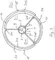
- Fig. 3 shows a cut through the tip of an apparatus of Fig. 1 of an apparatus in top view, the tip being cut at the level of its first guiding structure 303'.
- the implant 300 is represented by the shaft 1 comprising three apertures 9, 9' and 9'', a schematically shown first guiding structure 303 and openings 306', 306' and 306'' of the otherwise not shown posts 305, 305' and 305'' (the posts are, however, shown in Fig. 1 ).
- first tension threads 11, 14 and 15 are wound around the circumference of the implant 300 such that the circumference is covered or contacted by exactly two tension threads, either 11 and 15 (see left hand side), 11 and 14 (see below in Fig. 3 ) or 14 and 15 (see right hand side). This way, each part of the circumference is always covered by two tension threads.
- each of the tension threads 11, 14 and 15 covers about 2/3 (or about 240°) of the entire circumference of the implant 303 (or its guiding structure 303').
- Each of the tension threads 11, 14 and 15 extends from an inside of the shaft 1 through a first aperture, for example aperture 9, to a first opening, for example, opening 306 of a first post 305 around about 2/3 of the periphery and through a second opening, for example opening 306', of a second post, for example post 305' back into the inner space of the implant 300 and through a second aperture, for example, aperture 9' back into the inner space of the shaft 1.
- a first aperture for example aperture 9
- all tension threads are indicated as cut.
- the tension threads cover about 2/3 of the circumference in the embodiment of Fig. 3 .
- opening areas through which the tension threads are guided from an outside of the implant to the inside and which may reduce the periphery covered by two tension threads have not been counted.
- the periphery that is covered by two tension threads is a bit less than 360°. Therefore, in some embodiments according to the present invention a two thirds coverage may be understood such that the tension threads at issue extend only over two of three parts of the actually (by two tension threads) covered section of the periphery.
- Fig. 3 relates to the tension threads 11, 14 and 15 wound around the first guiding structure 303.
- tension threads 11', 14' and 15' wound around the second guiding structure 303' see Fig. 1 or Fig. 2 .
- the tension threads 11, 14 and 15 are all shown to have a certain distance to the first guiding structure 303 for the sake of clarity only. Obviously, during use, all these tension threads contact the first guiding structure 303 and apply tension onto the latter acting against the implants attitude to unfold following its shape-memory abilities.
- the reference sign I-i relates to the inner space or inside of the implant 300, I-s to the inner space or inside of the shaft 1, O-i to the outside of the implant 300, and O-s to the outside of the shaft 1.
Landscapes
- Health & Medical Sciences (AREA)
- Cardiology (AREA)
- Engineering & Computer Science (AREA)
- Biomedical Technology (AREA)
- Heart & Thoracic Surgery (AREA)
- Transplantation (AREA)
- Oral & Maxillofacial Surgery (AREA)
- Vascular Medicine (AREA)
- Life Sciences & Earth Sciences (AREA)
- Animal Behavior & Ethology (AREA)
- General Health & Medical Sciences (AREA)
- Public Health (AREA)
- Veterinary Medicine (AREA)
- Prostheses (AREA)
Claims (14)
- Ein faltbares und/oder entfaltbares medizinisches Implantat (300), aufweisend wenigstens drei Spannfäden (11, 14, 15, 11', 14', 15') zum Falten und/oder Entfalten des Implantats (300) sowie wenigstens eine erste Führungsstruktur (303) zum Führen einiger oder aller Spannfäden (11, 14, 15, 11', 14', 15') um das Implantat (300) entlang eines Äußeren oder eines Umfangs, dadurch gekennzeichnet, dass drei der Spannfäden (11, 14, 15, 11', 14', 15') um das Äußere oder den Umfang des Implantats (300) oder eine Führungsstruktur (303) derart gewunden sind, dass einige oder alle der Spannfäden (11, 14, 15, 11', 14', 15') jeweils genau oder ungefähr 2/3 des Äußeren oder des Umfangs abdecken bzw. berühren.
- Ein medizinisches Implantat (300) nach Anspruch 1, ferner aufweisend zumindest eine zweite Führungsstruktur (303') und wenigstens drei Streben (305, 305', 305"), wobei die wenigstens drei Streben (305, 305', 305") derart zwischen der ersten und der zweiten Führungsstruktur (303, 303') angeordnet sind, dass sie diese miteinander verbinden und/oder den Abstand zwischen diesen erhalten, wobei jede der wenigstens drei Streben (305, 305', 305") wenigstens zwei Öffnungen (306, 306', 306" , 307, 307', 307") aufweist, durch welche Spannfäden (11, 14, 15, 11', 14', 15') von einem Inneren des Implantats (300) zu einem Äußeren des Implantats (300) sowie zurück aus dem Äußeren in das Innere geführt werden, wobei die Spannfäden (11, 14, 15, 11', 14', 15') durch eine erste Öffnung (307, 307', 307") einer ersten Strebe (305, 305', 305") zum Äußeren und durch eine beliebige zweite erste Öffnung (307, 307', 307") einer beliebigen zweiten Strebe (305, 305', 305") zurück in das Innere geführt werden, wobei die erste Öffnung sich von der zweiten Öffnung unterscheidet und die erste Strebe sich von der zweiten Strebe unterscheidet.
- Ein medizinisches Implantat (300) nach Anspruch 1 oder nach Anspruch 2, welches genau drei Streben umfasst (305, 305', 305").
- Ein medizinisches Implantat (300) nach einem der vorangegangenen Ansprüche, wobei die Spannfäden (11, 14, 15, 11', 14', 15') um die erste und/oder um die zweite Führungsstruktur (303, 303') derart geführt werden, dass der Umfang des Implantats (300) oder der Umfang seiner Führungsstruktur(en) (303, 303') von nicht mehr als oder genau zwei Spannfäden (11' und 15', 11' und 14' , 14' und 15') bedeckt ist oder berührt wird.
- Ein medizinisches Implantat (300) nach einem der vorangegangenen Ansprüche, wobei das Implantat (300) ein Stent oder eine Herzklappenanordnung ist.
- Ein medizinisches Implantat (300) nach einem der vorhergehenden Ansprüche, wobei jeder der Spannfäden (11, 14, 15, 11', 14', 15') ein chirurgischer Nahtfaden, ein Seil, ein Filament, eine Schnur oder eine Kette mit einer Mehrzahl von verbundenen Kettengliedern ist.
- Ein medizinisches Implantat (300) nach einem der vorhergehenden Ansprüche, wobei das Implantat (300) drei Spannfäden bei einer oder jeder Längsebene des Implantats (300) aufweist.
- Eine Vorrichtung (100) zum Falten oder Entfalten des medizinischen Implantats (300) nach Anspruch 1 durch Ändern der auf das medizinische Implantat (300) aufgebrachten Spannung mittels zumindest drei Spannfäden (11, 14, 15, 11', 14', 15'), wobei die Vorrichtung (100) umfasst oder verbunden ist mit:- einem Schaft (1), der einen Aufnahme- oder Haltebereich (55) zum Aufnehmen des Implantats (300) umfasst, und- eine Spanneinrichtung zum Ändern einer Form des faltbaren und/oder entfaltbaren Implantats (300), die derart verbunden und angeordnet ist, eine Spannung mittels sämtlicher der Spannfäden (11, 14, 15, 11', 14', 15') auf das medizinische Implantat (300) auszuüben.
- Eine Vorrichtung (100) nach Anspruch 8, wobei ein Inneres des Schafts (1) permeabel ist oder zumindest in Abschnitten davon in der Längsrichtung des Schafts (1) passierbar ist, wobei der Schaft (1) eine Wand (3) umfasst, und wobei der Schaft (1) zumindest drei Schaftöffnungen (9, 9', 9") umfasst, durch welche Spannfäden (11, 14, 15, 11', 14', 15') zum Falten und/oder Entfalten des Implantats (300) eintreten und/oder austreten können, wobei die Spannfäden (11, 14, 15, 11', 14', 15') zum Falten und/oder Entfalten eines Implantats (300) mit der Spannvorrichtung der Vorrichtung (100) verbunden sind, wobei die Spannfäden (11, 14, 15, 11', 14', 15') von einem Inneren des Schafts (1) zu einem Äußeren des Schafts (1) und zurück von dem Äußeren in das Innere geführt sind, wobei die Spannfäden (11, 14, 15, 11', 14', 15') durch erste Öffnungen (9, 9', 9") nach Außen und zurück in das Innere durch eine zweite Öffnung (9, 9', 9") geführt sind, wobei die erste und die zweite Öffnung sich voneinander unterscheiden.
- Eine Vorrichtung (100) gemäß einem der Ansprüche 8 oder 9, wobei die Vorrichtung (100) drei Schaftöffnungen (9, 9', 9") aufweist, und wobei durch jede der drei Öffnungen (9, 9', 9"), zwei Spannfäden (11, 14, 15, 11', 14', 15') ein- oder austreten.
- Eine Vorrichtung (100) nach einem der Ansprüche 8 - 10, wobei der Schaft (1) starr oder flexibel in eine oder mehrere Richtungen ist.
- Eine Vorrichtung (100) nach Anspruch 9, wobei die zumindest drei Schaftöffnungen (9, 9', 9") alle bei der gleichen Höhe oder Längsebene der Vorrichtung angeordnet sind.
- Eine Vorrichtung (100) nach einem der Ansprüche 8 - 12, wobei jeder der Spannfäden (11, 14, 15, 11', 14', 15') chirurgischer Nahtfaden, ein Seil, ein Filament, eine Schnur oder eine Kette mit einer Mehrzahl von verbundenen Kettengliedern ist.
- Eine Vorrichtung (100) nach einem der Ansprüche 8 - 13, wobei das Implantat (300) drei Spannfäden bei jeder Längsebene des Implantats (300) aufweist.
Priority Applications (1)
| Application Number | Priority Date | Filing Date | Title |
|---|---|---|---|
| EP14723813.3A EP2996633B1 (de) | 2013-05-14 | 2014-05-14 | Vorrichtung zum einklappen oder aufklappen eines medizinischen implantats, und implantat |
Applications Claiming Priority (3)
| Application Number | Priority Date | Filing Date | Title |
|---|---|---|---|
| EP13002535.6A EP2803335B1 (de) | 2013-05-14 | 2013-05-14 | Vorrichtung zum Einklappen oder Aufklappen eines medizinischen Implantats, und Implantat |
| PCT/EP2014/059854 WO2014184249A1 (en) | 2013-05-14 | 2014-05-14 | Apparatus for folding or unfolding a medical implant, and implant |
| EP14723813.3A EP2996633B1 (de) | 2013-05-14 | 2014-05-14 | Vorrichtung zum einklappen oder aufklappen eines medizinischen implantats, und implantat |
Publications (2)
| Publication Number | Publication Date |
|---|---|
| EP2996633A1 EP2996633A1 (de) | 2016-03-23 |
| EP2996633B1 true EP2996633B1 (de) | 2020-09-23 |
Family
ID=48468123
Family Applications (2)
| Application Number | Title | Priority Date | Filing Date |
|---|---|---|---|
| EP13002535.6A Active EP2803335B1 (de) | 2013-05-14 | 2013-05-14 | Vorrichtung zum Einklappen oder Aufklappen eines medizinischen Implantats, und Implantat |
| EP14723813.3A Active EP2996633B1 (de) | 2013-05-14 | 2014-05-14 | Vorrichtung zum einklappen oder aufklappen eines medizinischen implantats, und implantat |
Family Applications Before (1)
| Application Number | Title | Priority Date | Filing Date |
|---|---|---|---|
| EP13002535.6A Active EP2803335B1 (de) | 2013-05-14 | 2013-05-14 | Vorrichtung zum Einklappen oder Aufklappen eines medizinischen Implantats, und Implantat |
Country Status (6)
| Country | Link |
|---|---|
| US (1) | US10188537B2 (de) |
| EP (2) | EP2803335B1 (de) |
| JP (2) | JP2016518211A (de) |
| CN (1) | CN105263444B (de) |
| CA (1) | CA2912450C (de) |
| WO (1) | WO2014184249A1 (de) |
Families Citing this family (20)
| Publication number | Priority date | Publication date | Assignee | Title |
|---|---|---|---|---|
| US8579964B2 (en) | 2010-05-05 | 2013-11-12 | Neovasc Inc. | Transcatheter mitral valve prosthesis |
| US9554897B2 (en) | 2011-04-28 | 2017-01-31 | Neovasc Tiara Inc. | Methods and apparatus for engaging a valve prosthesis with tissue |
| US9308087B2 (en) | 2011-04-28 | 2016-04-12 | Neovasc Tiara Inc. | Sequentially deployed transcatheter mitral valve prosthesis |
| US9345573B2 (en) | 2012-05-30 | 2016-05-24 | Neovasc Tiara Inc. | Methods and apparatus for loading a prosthesis onto a delivery system |
| US9572665B2 (en) | 2013-04-04 | 2017-02-21 | Neovasc Tiara Inc. | Methods and apparatus for delivering a prosthetic valve to a beating heart |
| DE202016008737U1 (de) | 2015-12-15 | 2019-04-05 | Neovasc Tiara Inc. | Transseptales Zuführsystem |
| CN108882981B (zh) | 2016-01-29 | 2021-08-10 | 内奥瓦斯克迪亚拉公司 | 用于防止流出阻塞的假体瓣膜 |
| EP4349276A3 (de) | 2016-05-05 | 2024-06-19 | Teleflex Life Sciences LLC | Lösbare längliche anordnung |
| CN109996581B (zh) | 2016-11-21 | 2021-10-15 | 内奥瓦斯克迪亚拉公司 | 用于快速收回经导管心脏瓣膜递送系统的方法和系统 |
| WO2018156854A1 (en) | 2017-02-24 | 2018-08-30 | Bolton Medical, Inc. | Radially adjustable stent graft delivery system |
| CN109843226B (zh) | 2017-02-24 | 2022-05-17 | 波顿医疗公司 | 用于径向收缩支架移植物的递送系统和使用方法 |
| WO2018156842A1 (en) | 2017-02-24 | 2018-08-30 | Bolton Medical, Inc. | System and method to radially constrict a stent graft |
| CA3073834A1 (en) | 2017-08-25 | 2019-02-28 | Neovasc Tiara Inc. | Sequentially deployed transcatheter mitral valve prosthesis |
| CN112423710B (zh) * | 2018-07-18 | 2024-11-26 | W.L.戈尔及同仁股份有限公司 | 可植入医疗设备展开系统 |
| WO2020093172A1 (en) | 2018-11-08 | 2020-05-14 | Neovasc Tiara Inc. | Ventricular deployment of a transcatheter mitral valve prosthesis |
| WO2020185597A1 (en) | 2019-03-08 | 2020-09-17 | Neovasc Tiara Inc. | Retrievable prosthesis delivery system |
| US11602429B2 (en) | 2019-04-01 | 2023-03-14 | Neovasc Tiara Inc. | Controllably deployable prosthetic valve |
| EP3952792A4 (de) | 2019-04-10 | 2023-01-04 | Neovasc Tiara Inc. | Herzklappenprothese mit natürlichem blutfluss |
| EP3972673B1 (de) | 2019-05-20 | 2026-01-28 | Neovasc Tiara Inc. | Einführungsvorrichtung mit hämostasemechanismus |
| CN114144144B (zh) | 2019-06-20 | 2026-01-13 | 内奥瓦斯克迪亚拉公司 | 低轮廓假体二尖瓣 |
Citations (1)
| Publication number | Priority date | Publication date | Assignee | Title |
|---|---|---|---|---|
| EP2826443A1 (de) * | 2013-07-16 | 2015-01-21 | Transcatheter Technologies GmbH | Satz mit einer Vorrichtung und ein medizinisches Implantat |
Family Cites Families (10)
| Publication number | Priority date | Publication date | Assignee | Title |
|---|---|---|---|---|
| FR2863160B1 (fr) * | 2003-12-09 | 2006-03-03 | Perouse Laboratoires | Dispositif de traitement d'un vaisseau sanguin et procede de preparation de ce dispositif |
| EP1991168B1 (de) * | 2006-02-16 | 2016-01-27 | Transcatheter Technologies GmbH | Minimalinvasiver herzklappenersatz |
| AU2009205739B2 (en) * | 2008-01-16 | 2014-09-25 | St. Jude Medical, Inc. | Delivery and retrieval systems for collapsible/expandable prosthetic heart valves |
| DE102008012113A1 (de) * | 2008-03-02 | 2009-09-03 | Transcatheter Technologies Gmbh | Stent, welcher vom expandierten Zustand erneut im Durchmesser kontrolliert verringerbar ist |
| DE102009055969A1 (de) * | 2009-11-27 | 2011-06-01 | Transcatheter Technologies Gmbh | Vorrichtung und Set zum Falten oder Entfalten eines medizinischen Implantats und Verfahren |
| DE102010008338A1 (de) | 2010-02-17 | 2011-08-18 | Transcatheter Technologies GmbH, 93053 | Einrichtung, vorgesehen, um an einem Katheter befestigt oder mit diesem verbunden zu werden, Katheter und Verfahren |
| DE102010061371A1 (de) * | 2010-12-20 | 2012-06-21 | Transcatheter Technologies Gmbh | Vorrichtung mit individuellen Schaftfasern und Set zum Falten oder Entfalten eines medizinischen Implantats und Verfahren |
| EP2918245B1 (de) | 2014-03-14 | 2017-05-03 | Venus MedTech (HangZhou), Inc. | Herzklappe mit einem Stück Krone, das mit Blättchen, einer oberen Manschette und einer unteren Manschette verbunden ist; und medizinisches Implantat |
| EP2832318B1 (de) | 2013-07-31 | 2017-04-05 | Venus MedTech (HangZhou), Inc. | Griffanordnung für eine Implantatausgabevorrichtung mit einem Kraftbegrenzer, einem Versetzungsbegrenzer und/oder einer Bremsrahmenanordnung |
| EP2918246B1 (de) | 2014-03-14 | 2018-08-08 | Venus MedTech (HangZhou), Inc. | Herzklappenanordnung mit doppelter Abdichtung |
-
2013
- 2013-05-14 EP EP13002535.6A patent/EP2803335B1/de active Active
-
2014
- 2014-05-14 JP JP2016513351A patent/JP2016518211A/ja active Pending
- 2014-05-14 EP EP14723813.3A patent/EP2996633B1/de active Active
- 2014-05-14 WO PCT/EP2014/059854 patent/WO2014184249A1/en not_active Ceased
- 2014-05-14 CA CA2912450A patent/CA2912450C/en active Active
- 2014-05-14 CN CN201480027648.6A patent/CN105263444B/zh active Active
- 2014-05-14 US US14/891,261 patent/US10188537B2/en active Active
-
2019
- 2019-02-21 JP JP2019029052A patent/JP6660499B2/ja active Active
Patent Citations (1)
| Publication number | Priority date | Publication date | Assignee | Title |
|---|---|---|---|---|
| EP2826443A1 (de) * | 2013-07-16 | 2015-01-21 | Transcatheter Technologies GmbH | Satz mit einer Vorrichtung und ein medizinisches Implantat |
Also Published As
| Publication number | Publication date |
|---|---|
| EP2996633A1 (de) | 2016-03-23 |
| CA2912450C (en) | 2021-05-25 |
| EP2803335A1 (de) | 2014-11-19 |
| JP6660499B2 (ja) | 2020-03-11 |
| CN105263444B (zh) | 2018-08-14 |
| US10188537B2 (en) | 2019-01-29 |
| JP2016518211A (ja) | 2016-06-23 |
| CA2912450A1 (en) | 2014-11-20 |
| US20160250050A1 (en) | 2016-09-01 |
| CN105263444A (zh) | 2016-01-20 |
| WO2014184249A1 (en) | 2014-11-20 |
| EP2803335B1 (de) | 2017-09-27 |
| JP2019093204A (ja) | 2019-06-20 |
Similar Documents
| Publication | Publication Date | Title |
|---|---|---|
| CA2912450C (en) | Apparatus for folding or unfolding a medical implant, and implant | |
| EP2832317B1 (de) | Implantatausgabevorrichtung zum Einklappen oder Aufklappen eines medizinischen Implantats | |
| EP2938291B2 (de) | Vorrichtung und set zum zusammenklappen oder aufklappen eines medizinischen implantats mit einem klemmmechanismus | |
| US20160250051A1 (en) | Set comprising a catheter and a valve supporting implant | |
| US11020230B2 (en) | Device for performing or preparing for a mitral valve annuloplasty by a transfemoral approach | |
| CA2715195C (en) | Stent which is reducible again in its diameter from an expanded state in a controlled manner | |
| EP3294220B1 (de) | Vorrichtungen und systeme zur herzklappenfreisetzung | |
| JP6508837B2 (ja) | 器具と医療用インプラントとを含むセット | |
| JP4268050B2 (ja) | ガストロストミー用器具パッケイジおよび組立て方法 | |
| ES3019365T3 (en) | Prosthetic heart valve | |
| EP3324891B1 (de) | Vorrichtung zum einsetzen eines selbstexpandierenden medizinischen geräts | |
| US20150073538A1 (en) | Alignment of an implantable medical device | |
| BR112015002933B1 (pt) | Dispositivo implantável para uso no corpo humano e/ou animal para substituir uma válvula de um órgão. | |
| CN103338725B (zh) | 包括各别轴纤维的装置以及用于折叠或展开医用植入体的套组、以及方法 |
Legal Events
| Date | Code | Title | Description |
|---|---|---|---|
| PUAI | Public reference made under article 153(3) epc to a published international application that has entered the european phase |
Free format text: ORIGINAL CODE: 0009012 |
|
| 17P | Request for examination filed |
Effective date: 20151214 |
|
| AK | Designated contracting states |
Kind code of ref document: A1 Designated state(s): AL AT BE BG CH CY CZ DE DK EE ES FI FR GB GR HR HU IE IS IT LI LT LU LV MC MK MT NL NO PL PT RO RS SE SI SK SM TR |
|
| AX | Request for extension of the european patent |
Extension state: BA ME |
|
| DAX | Request for extension of the european patent (deleted) | ||
| RAP1 | Party data changed (applicant data changed or rights of an application transferred) |
Owner name: VENUS MEDTECH (HANGZHOU), INC. |
|
| STAA | Information on the status of an ep patent application or granted ep patent |
Free format text: STATUS: EXAMINATION IS IN PROGRESS |
|
| 17Q | First examination report despatched |
Effective date: 20161125 |
|
| GRAP | Despatch of communication of intention to grant a patent |
Free format text: ORIGINAL CODE: EPIDOSNIGR1 |
|
| STAA | Information on the status of an ep patent application or granted ep patent |
Free format text: STATUS: GRANT OF PATENT IS INTENDED |
|
| INTG | Intention to grant announced |
Effective date: 20200414 |
|
| INTG | Intention to grant announced |
Effective date: 20200414 |
|
| GRAS | Grant fee paid |
Free format text: ORIGINAL CODE: EPIDOSNIGR3 |
|
| GRAA | (expected) grant |
Free format text: ORIGINAL CODE: 0009210 |
|
| STAA | Information on the status of an ep patent application or granted ep patent |
Free format text: STATUS: THE PATENT HAS BEEN GRANTED |
|
| AK | Designated contracting states |
Kind code of ref document: B1 Designated state(s): AL AT BE BG CH CY CZ DE DK EE ES FI FR GB GR HR HU IE IS IT LI LT LU LV MC MK MT NL NO PL PT RO RS SE SI SK SM TR |
|
| REG | Reference to a national code |
Ref country code: GB Ref legal event code: FG4D |
|
| REG | Reference to a national code |
Ref country code: CH Ref legal event code: EP |
|
| REG | Reference to a national code |
Ref country code: DE Ref legal event code: R096 Ref document number: 602014070460 Country of ref document: DE |
|
| REG | Reference to a national code |
Ref country code: IE Ref legal event code: FG4D |
|
| REG | Reference to a national code |
Ref country code: AT Ref legal event code: REF Ref document number: 1315607 Country of ref document: AT Kind code of ref document: T Effective date: 20201015 |
|
| REG | Reference to a national code |
Ref country code: NL Ref legal event code: FP |
|
| PG25 | Lapsed in a contracting state [announced via postgrant information from national office to epo] |
Ref country code: SE Free format text: LAPSE BECAUSE OF FAILURE TO SUBMIT A TRANSLATION OF THE DESCRIPTION OR TO PAY THE FEE WITHIN THE PRESCRIBED TIME-LIMIT Effective date: 20200923 Ref country code: NO Free format text: LAPSE BECAUSE OF FAILURE TO SUBMIT A TRANSLATION OF THE DESCRIPTION OR TO PAY THE FEE WITHIN THE PRESCRIBED TIME-LIMIT Effective date: 20201223 Ref country code: BG Free format text: LAPSE BECAUSE OF FAILURE TO SUBMIT A TRANSLATION OF THE DESCRIPTION OR TO PAY THE FEE WITHIN THE PRESCRIBED TIME-LIMIT Effective date: 20201223 Ref country code: GR Free format text: LAPSE BECAUSE OF FAILURE TO SUBMIT A TRANSLATION OF THE DESCRIPTION OR TO PAY THE FEE WITHIN THE PRESCRIBED TIME-LIMIT Effective date: 20201224 Ref country code: HR Free format text: LAPSE BECAUSE OF FAILURE TO SUBMIT A TRANSLATION OF THE DESCRIPTION OR TO PAY THE FEE WITHIN THE PRESCRIBED TIME-LIMIT Effective date: 20200923 Ref country code: FI Free format text: LAPSE BECAUSE OF FAILURE TO SUBMIT A TRANSLATION OF THE DESCRIPTION OR TO PAY THE FEE WITHIN THE PRESCRIBED TIME-LIMIT Effective date: 20200923 |
|
| REG | Reference to a national code |
Ref country code: AT Ref legal event code: MK05 Ref document number: 1315607 Country of ref document: AT Kind code of ref document: T Effective date: 20200923 |
|
| PG25 | Lapsed in a contracting state [announced via postgrant information from national office to epo] |
Ref country code: RS Free format text: LAPSE BECAUSE OF FAILURE TO SUBMIT A TRANSLATION OF THE DESCRIPTION OR TO PAY THE FEE WITHIN THE PRESCRIBED TIME-LIMIT Effective date: 20200923 Ref country code: LV Free format text: LAPSE BECAUSE OF FAILURE TO SUBMIT A TRANSLATION OF THE DESCRIPTION OR TO PAY THE FEE WITHIN THE PRESCRIBED TIME-LIMIT Effective date: 20200923 |
|
| REG | Reference to a national code |
Ref country code: LT Ref legal event code: MG4D |
|
| PG25 | Lapsed in a contracting state [announced via postgrant information from national office to epo] |
Ref country code: EE Free format text: LAPSE BECAUSE OF FAILURE TO SUBMIT A TRANSLATION OF THE DESCRIPTION OR TO PAY THE FEE WITHIN THE PRESCRIBED TIME-LIMIT Effective date: 20200923 Ref country code: CZ Free format text: LAPSE BECAUSE OF FAILURE TO SUBMIT A TRANSLATION OF THE DESCRIPTION OR TO PAY THE FEE WITHIN THE PRESCRIBED TIME-LIMIT Effective date: 20200923 Ref country code: RO Free format text: LAPSE BECAUSE OF FAILURE TO SUBMIT A TRANSLATION OF THE DESCRIPTION OR TO PAY THE FEE WITHIN THE PRESCRIBED TIME-LIMIT Effective date: 20200923 Ref country code: SM Free format text: LAPSE BECAUSE OF FAILURE TO SUBMIT A TRANSLATION OF THE DESCRIPTION OR TO PAY THE FEE WITHIN THE PRESCRIBED TIME-LIMIT Effective date: 20200923 Ref country code: LT Free format text: LAPSE BECAUSE OF FAILURE TO SUBMIT A TRANSLATION OF THE DESCRIPTION OR TO PAY THE FEE WITHIN THE PRESCRIBED TIME-LIMIT Effective date: 20200923 Ref country code: PT Free format text: LAPSE BECAUSE OF FAILURE TO SUBMIT A TRANSLATION OF THE DESCRIPTION OR TO PAY THE FEE WITHIN THE PRESCRIBED TIME-LIMIT Effective date: 20210125 |
|
| PG25 | Lapsed in a contracting state [announced via postgrant information from national office to epo] |
Ref country code: AT Free format text: LAPSE BECAUSE OF FAILURE TO SUBMIT A TRANSLATION OF THE DESCRIPTION OR TO PAY THE FEE WITHIN THE PRESCRIBED TIME-LIMIT Effective date: 20200923 Ref country code: AL Free format text: LAPSE BECAUSE OF FAILURE TO SUBMIT A TRANSLATION OF THE DESCRIPTION OR TO PAY THE FEE WITHIN THE PRESCRIBED TIME-LIMIT Effective date: 20200923 Ref country code: ES Free format text: LAPSE BECAUSE OF FAILURE TO SUBMIT A TRANSLATION OF THE DESCRIPTION OR TO PAY THE FEE WITHIN THE PRESCRIBED TIME-LIMIT Effective date: 20200923 Ref country code: PL Free format text: LAPSE BECAUSE OF FAILURE TO SUBMIT A TRANSLATION OF THE DESCRIPTION OR TO PAY THE FEE WITHIN THE PRESCRIBED TIME-LIMIT Effective date: 20200923 Ref country code: IS Free format text: LAPSE BECAUSE OF FAILURE TO SUBMIT A TRANSLATION OF THE DESCRIPTION OR TO PAY THE FEE WITHIN THE PRESCRIBED TIME-LIMIT Effective date: 20210123 |
|
| REG | Reference to a national code |
Ref country code: DE Ref legal event code: R097 Ref document number: 602014070460 Country of ref document: DE |
|
| PG25 | Lapsed in a contracting state [announced via postgrant information from national office to epo] |
Ref country code: SK Free format text: LAPSE BECAUSE OF FAILURE TO SUBMIT A TRANSLATION OF THE DESCRIPTION OR TO PAY THE FEE WITHIN THE PRESCRIBED TIME-LIMIT Effective date: 20200923 |
|
| PLBE | No opposition filed within time limit |
Free format text: ORIGINAL CODE: 0009261 |
|
| STAA | Information on the status of an ep patent application or granted ep patent |
Free format text: STATUS: NO OPPOSITION FILED WITHIN TIME LIMIT |
|
| PG25 | Lapsed in a contracting state [announced via postgrant information from national office to epo] |
Ref country code: SI Free format text: LAPSE BECAUSE OF FAILURE TO SUBMIT A TRANSLATION OF THE DESCRIPTION OR TO PAY THE FEE WITHIN THE PRESCRIBED TIME-LIMIT Effective date: 20200923 Ref country code: DK Free format text: LAPSE BECAUSE OF FAILURE TO SUBMIT A TRANSLATION OF THE DESCRIPTION OR TO PAY THE FEE WITHIN THE PRESCRIBED TIME-LIMIT Effective date: 20200923 |
|
| 26N | No opposition filed |
Effective date: 20210624 |
|
| PG25 | Lapsed in a contracting state [announced via postgrant information from national office to epo] |
Ref country code: IT Free format text: LAPSE BECAUSE OF FAILURE TO SUBMIT A TRANSLATION OF THE DESCRIPTION OR TO PAY THE FEE WITHIN THE PRESCRIBED TIME-LIMIT Effective date: 20200923 |
|
| PG25 | Lapsed in a contracting state [announced via postgrant information from national office to epo] |
Ref country code: MC Free format text: LAPSE BECAUSE OF FAILURE TO SUBMIT A TRANSLATION OF THE DESCRIPTION OR TO PAY THE FEE WITHIN THE PRESCRIBED TIME-LIMIT Effective date: 20200923 Ref country code: LU Free format text: LAPSE BECAUSE OF NON-PAYMENT OF DUE FEES Effective date: 20210514 |
|
| REG | Reference to a national code |
Ref country code: BE Ref legal event code: MM Effective date: 20210531 |
|
| PG25 | Lapsed in a contracting state [announced via postgrant information from national office to epo] |
Ref country code: IE Free format text: LAPSE BECAUSE OF NON-PAYMENT OF DUE FEES Effective date: 20210514 |
|
| PG25 | Lapsed in a contracting state [announced via postgrant information from national office to epo] |
Ref country code: BE Free format text: LAPSE BECAUSE OF NON-PAYMENT OF DUE FEES Effective date: 20210531 |
|
| PG25 | Lapsed in a contracting state [announced via postgrant information from national office to epo] |
Ref country code: HU Free format text: LAPSE BECAUSE OF FAILURE TO SUBMIT A TRANSLATION OF THE DESCRIPTION OR TO PAY THE FEE WITHIN THE PRESCRIBED TIME-LIMIT; INVALID AB INITIO Effective date: 20140514 |
|
| PG25 | Lapsed in a contracting state [announced via postgrant information from national office to epo] |
Ref country code: CY Free format text: LAPSE BECAUSE OF FAILURE TO SUBMIT A TRANSLATION OF THE DESCRIPTION OR TO PAY THE FEE WITHIN THE PRESCRIBED TIME-LIMIT Effective date: 20200923 |
|
| PGFP | Annual fee paid to national office [announced via postgrant information from national office to epo] |
Ref country code: NL Payment date: 20230519 Year of fee payment: 10 Ref country code: CH Payment date: 20230605 Year of fee payment: 10 |
|
| PG25 | Lapsed in a contracting state [announced via postgrant information from national office to epo] |
Ref country code: MK Free format text: LAPSE BECAUSE OF FAILURE TO SUBMIT A TRANSLATION OF THE DESCRIPTION OR TO PAY THE FEE WITHIN THE PRESCRIBED TIME-LIMIT Effective date: 20200923 |
|
| PG25 | Lapsed in a contracting state [announced via postgrant information from national office to epo] |
Ref country code: MT Free format text: LAPSE BECAUSE OF FAILURE TO SUBMIT A TRANSLATION OF THE DESCRIPTION OR TO PAY THE FEE WITHIN THE PRESCRIBED TIME-LIMIT Effective date: 20200923 |
|
| REG | Reference to a national code |
Ref country code: CH Ref legal event code: PL |
|
| REG | Reference to a national code |
Ref country code: NL Ref legal event code: MM Effective date: 20240601 |
|
| PG25 | Lapsed in a contracting state [announced via postgrant information from national office to epo] |
Ref country code: CH Free format text: LAPSE BECAUSE OF NON-PAYMENT OF DUE FEES Effective date: 20240531 |
|
| PG25 | Lapsed in a contracting state [announced via postgrant information from national office to epo] |
Ref country code: NL Free format text: LAPSE BECAUSE OF NON-PAYMENT OF DUE FEES Effective date: 20240601 |
|
| PGFP | Annual fee paid to national office [announced via postgrant information from national office to epo] |
Ref country code: DE Payment date: 20250519 Year of fee payment: 12 |
|
| PGFP | Annual fee paid to national office [announced via postgrant information from national office to epo] |
Ref country code: GB Payment date: 20250522 Year of fee payment: 12 |
|
| PGFP | Annual fee paid to national office [announced via postgrant information from national office to epo] |
Ref country code: FR Payment date: 20250521 Year of fee payment: 12 |
|
| PG25 | Lapsed in a contracting state [announced via postgrant information from national office to epo] |
Ref country code: TR Free format text: LAPSE BECAUSE OF FAILURE TO SUBMIT A TRANSLATION OF THE DESCRIPTION OR TO PAY THE FEE WITHIN THE PRESCRIBED TIME-LIMIT Effective date: 20200923 |