EP2996227B1 - Gebläsegehäuse, insbesondere für ein gebläse für ein fahrzeugheizgerät - Google Patents
Gebläsegehäuse, insbesondere für ein gebläse für ein fahrzeugheizgerät Download PDFInfo
- Publication number
- EP2996227B1 EP2996227B1 EP15181552.9A EP15181552A EP2996227B1 EP 2996227 B1 EP2996227 B1 EP 2996227B1 EP 15181552 A EP15181552 A EP 15181552A EP 2996227 B1 EP2996227 B1 EP 2996227B1
- Authority
- EP
- European Patent Office
- Prior art keywords
- motor housing
- contacting
- area
- blower
- contact element
- Prior art date
- Legal status (The legal status is an assumption and is not a legal conclusion. Google has not performed a legal analysis and makes no representation as to the accuracy of the status listed.)
- Active
Links
Images


Classifications
-
- F—MECHANICAL ENGINEERING; LIGHTING; HEATING; WEAPONS; BLASTING
- F04—POSITIVE - DISPLACEMENT MACHINES FOR LIQUIDS; PUMPS FOR LIQUIDS OR ELASTIC FLUIDS
- F04D—NON-POSITIVE-DISPLACEMENT PUMPS
- F04D25/00—Pumping installations or systems
- F04D25/02—Units comprising pumps and their driving means
- F04D25/06—Units comprising pumps and their driving means the pump being electrically driven
-
- H—ELECTRICITY
- H02—GENERATION; CONVERSION OR DISTRIBUTION OF ELECTRIC POWER
- H02K—DYNAMO-ELECTRIC MACHINES
- H02K5/00—Casings; Enclosures; Supports
- H02K5/04—Casings or enclosures characterised by the shape, form or construction thereof
- H02K5/22—Auxiliary parts of casings not covered by groups H02K5/06-H02K5/20, e.g. shaped to form connection boxes or terminal boxes
- H02K5/225—Terminal boxes or connection arrangements
-
- F—MECHANICAL ENGINEERING; LIGHTING; HEATING; WEAPONS; BLASTING
- F04—POSITIVE - DISPLACEMENT MACHINES FOR LIQUIDS; PUMPS FOR LIQUIDS OR ELASTIC FLUIDS
- F04D—NON-POSITIVE-DISPLACEMENT PUMPS
- F04D17/00—Radial-flow pumps, e.g. centrifugal pumps; Helico-centrifugal pumps
- F04D17/08—Centrifugal pumps
- F04D17/10—Centrifugal pumps for compressing or evacuating
-
- F—MECHANICAL ENGINEERING; LIGHTING; HEATING; WEAPONS; BLASTING
- F04—POSITIVE - DISPLACEMENT MACHINES FOR LIQUIDS; PUMPS FOR LIQUIDS OR ELASTIC FLUIDS
- F04D—NON-POSITIVE-DISPLACEMENT PUMPS
- F04D23/00—Other rotary non-positive-displacement pumps
- F04D23/008—Regenerative pumps
-
- F—MECHANICAL ENGINEERING; LIGHTING; HEATING; WEAPONS; BLASTING
- F04—POSITIVE - DISPLACEMENT MACHINES FOR LIQUIDS; PUMPS FOR LIQUIDS OR ELASTIC FLUIDS
- F04D—NON-POSITIVE-DISPLACEMENT PUMPS
- F04D25/00—Pumping installations or systems
- F04D25/02—Units comprising pumps and their driving means
- F04D25/06—Units comprising pumps and their driving means the pump being electrically driven
- F04D25/068—Mechanical details of the pump control unit
-
- F—MECHANICAL ENGINEERING; LIGHTING; HEATING; WEAPONS; BLASTING
- F04—POSITIVE - DISPLACEMENT MACHINES FOR LIQUIDS; PUMPS FOR LIQUIDS OR ELASTIC FLUIDS
- F04D—NON-POSITIVE-DISPLACEMENT PUMPS
- F04D25/00—Pumping installations or systems
- F04D25/02—Units comprising pumps and their driving means
- F04D25/06—Units comprising pumps and their driving means the pump being electrically driven
- F04D25/0693—Details or arrangements of the wiring
-
- F—MECHANICAL ENGINEERING; LIGHTING; HEATING; WEAPONS; BLASTING
- F04—POSITIVE - DISPLACEMENT MACHINES FOR LIQUIDS; PUMPS FOR LIQUIDS OR ELASTIC FLUIDS
- F04D—NON-POSITIVE-DISPLACEMENT PUMPS
- F04D29/00—Details, component parts, or accessories
- F04D29/02—Selection of particular materials
- F04D29/023—Selection of particular materials especially adapted for elastic fluid pumps
-
- F—MECHANICAL ENGINEERING; LIGHTING; HEATING; WEAPONS; BLASTING
- F04—POSITIVE - DISPLACEMENT MACHINES FOR LIQUIDS; PUMPS FOR LIQUIDS OR ELASTIC FLUIDS
- F04D—NON-POSITIVE-DISPLACEMENT PUMPS
- F04D29/00—Details, component parts, or accessories
- F04D29/40—Casings; Connections of working fluid
- F04D29/403—Casings; Connections of working fluid especially adapted for elastic fluid pumps
-
- F—MECHANICAL ENGINEERING; LIGHTING; HEATING; WEAPONS; BLASTING
- F04—POSITIVE - DISPLACEMENT MACHINES FOR LIQUIDS; PUMPS FOR LIQUIDS OR ELASTIC FLUIDS
- F04D—NON-POSITIVE-DISPLACEMENT PUMPS
- F04D29/00—Details, component parts, or accessories
- F04D29/60—Mounting; Assembling; Disassembling
- F04D29/601—Mounting; Assembling; Disassembling specially adapted for elastic fluid pumps
-
- H—ELECTRICITY
- H02—GENERATION; CONVERSION OR DISTRIBUTION OF ELECTRIC POWER
- H02K—DYNAMO-ELECTRIC MACHINES
- H02K7/00—Arrangements for handling mechanical energy structurally associated with dynamo-electric machines, e.g. structural association with mechanical driving motors or auxiliary dynamo-electric machines
- H02K7/14—Structural association with mechanical loads, e.g. with hand-held machine tools or fans
Definitions
- the present invention relates to a blower housing, in particular for a blower for a vehicle heater, which blower housing comprises a motor housing having a peripheral wall and a first bottom wall in a first axial end region of the peripheral wall.
- Blowers used in vehicle heaters for conveying combustion air may be designed as so-called side channel blowers.
- an electric motor with a stator and a rotor and a rotor shaft associated therewith is arranged.
- a first bottom wall is provided which on the one hand axially limits the interior of the motor housing and on the other hand extends radially beyond the peripheral wall.
- a ring-like conveying channel is arranged on the axial side facing away from the peripheral wall, which is covered by a conveying wheel carried on the rotor shaft.
- air is thus conveyed along the annular delivery channel under pressure buildup.
- the entering into an inlet region in the conveying channel air is discharged in a ring-like conveying channel in the circumferential direction interrupting the interruption area from the conveyor channel and directed, for example, toward a combustion chamber of a fuel-powered vehicle heater.
- Such a blower is from the DE 10 2010 041 139 A1 known.
- This fan has a fan housing according to the preamble of claim 1.
- a ECU housing portion provided, which has on its side remote from the peripheral wall side closed by a closure element opening.
- contacting areas are provided on both sides of the peripheral wall, via which the electric motor can be connected to a vehicle line system.
- a corresponding contacting region is provided in the closure element which terminates the opening of the control device housing region.
- a fan housing in particular for a fan for a vehicle heater, comprising a motor housing having a peripheral wall and a first bottom portion in a first axial end portion of the peripheral wall, connectable to the motor housing in a second axial end portion of the peripheral wall and a motor housing cover providing a second floor area, on the motor housing cover a contacting arrangement for electrical contacting of an electric motor to be arranged in the blower housing, wherein the contacting arrangement comprises in a first contacting area a first contacting formation at least on one side of the motor housing cover to be positioned facing an interior of the motor housing outside exposed second Beneficiier Scheme comprises a second Kunststoffierformation, as well as a direct the first Kunststoffierformation with the second Kunststoffierformation d connecting strip formation includes.
- the electrical contacting of the electric motor to be arranged in an interior of the motor housing or the blower housing takes place via the motor housing cover to be connected axially to the motor housing.
- the structure is preferably such that, when the motor housing cover is attached to the motor housing, the first contacting area is brought into contact with motor contact elements provided on an electric motor.
- exposed second Kunststoffier Kunststoff the electrical connection to a control device, for example via a connector, done.
- the contacting is at least partially embedded in a building material of the motor housing cover.
- Embedded in the sense of the present invention means that the embedded assembly in the manufacture of the motor housing cover surrounded by the construction material thereof, for example, encapsulated, and thus is firmly integrated after solidification of the building material of the motor housing cover in this by the embedding.
- the first Kunststoffierformation comprises a plurality of first contact elements, that the second Mixierformation associated with each first contact element at least one second contact element comprises, and that the conductor track formation in association with each first contact element comprises a this connecting with at least one associated second contact element trace.
- a particularly easy-to-implement construction can be obtained by integrally forming at least one printed conductor element with an associated first contact element and / or at least one associated second contact element, preferably by separating it from a printed conductor material blank, wherein it can be provided for the simple production of a respective electrical contact in that at least one first contact element or / and at least one second contact element comprises a plug-in contact element.
- the motor housing cover connect the first contacting region to the second contacting region.
- the motor housing cover connects the first contacting region to the second contacting region.
- the second contacting region on one of the second bottom region remote end region of the connecting web comprises a contact plug connection region.
- blower housing according to the invention can be further supported that the second bottom portion of the motor housing cover is integrally formed with the connecting web and a Needlessteckan gleich Symposium, wherein advantageously the motor housing cover as a plastic-metal composite component, ie in plastic-metal composite technology formed is.
- a high variability in the installation or in the connectability to a control device can be further provided by the fact that the motor housing cover with the motor housing in a plurality of relative to each other about a motor housing longitudinal axis twisted mounting positions can be connected.
- the present invention further relates to a blower, in particular for a vehicle heater, comprising a blower housing constructed according to the invention and an electric motor arranged in the blower housing with a stator and a rotor.
- the rotor may comprise a rotor shaft. This may preferably be mounted on the first floor area and / or on the second floor area, wherein when stored on the second floor area of the motor housing cover not only the functionality of the completion of the interior of the motor housing and the electrical contact, but also the storage can take.
- the first bottom region extend radially beyond the circumferential wall with respect to a motor housing longitudinal axis such that an axial side of the first bottom wall facing away from the peripheral wall forms a recess annularly extending around the motor housing longitudinal axis conveying channel is provided in the first bottom wall, and that at one of the first Bottom wall passing through the rotor shaft, a conveyor channel covering the conveyor wheel is supported.
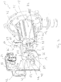
- Fig. 1 and 2 show in perspective view a generally designated 10 fan, which is designed as a so-called side channel blower and can be used to promote in a vehicle heater, the combustion air required for combustion combustion air toward a combustion chamber.
- a generally designated 10 fan which is designed as a so-called side channel blower and can be used to promote in a vehicle heater, the combustion air required for combustion combustion air toward a combustion chamber.
- the blower 10 includes a blower housing, generally designated 12.
- the fan housing 12 comprises a motor housing 14 and a motor housing cover 16 to be connected thereto.
- the motor housing 14 is constructed with a peripheral wall 18 and at a first axial end area 20 thereof a first floor area generally designated 22.
- the peripheral wall 18 and the first bottom portion 22 define an inner space 24 of the motor housing 12, in which a in Fig. 2 partially detectable electric motor 26 is received.
- the electric motor 26 includes a stator fixedly supported, for example, on the peripheral wall 18, and a rotor having a rotor shaft 28 rotatable about an axis of rotation. wherein this axis of rotation of the rotor shaft 28 may simultaneously correspond to a motor housing longitudinal axis D, along which extends, for example, the substantially cylindrical peripheral wall 18 extends.
- the first bottom portion 22 extends with respect to the motor housing longitudinal axis D radially beyond the peripheral wall 18 and, for example, in the extending beyond the peripheral wall 18 extending radially extending area around the motor housing longitudinal axis D ring-like conveying channel ready to one in the figures unrecognizable axial side 29 of the bottom portion 22 is open.
- a conveying wheel likewise not shown in the figures, is supported on an end region of the rotor shaft 28 passing through the first bottom region 22 and covers the conveying channel with its conveying vanes, so that air is conveyed under pressure build-up in the circumferential direction along the conveying channel during rotation of the conveying wheel and this in the Leave the area of a breaker area.
- the motor housing 12 with its circumferential wall 18 and the first floor area 22 is preferably made of metal material, for example aluminum in an aluminum die casting process.
- the one in the in Fig. 1 recognizable state of assembly the interior 26 of the motor housing 14 final motor housing cover 16 is preferably made of plastic material, for example as a plastic injection molded part.
- the motor housing cover 16 provides a second floor area 30 that substantially closes the interior 26 in the axial direction. From this, projecting in the direction of the motor housing longitudinal axis D, approximately cylindrically shaped engagement portion 32 project, which engages in the assembled state in the peripheral wall 18 to ensure a closure of the interior 26. At three, for example, evenly, so an angular distance of 120 °, provided to each other on the peripheral wall 18, radially outwardly projecting connecting portions 34, the motor housing cover 16 may be fixed with connecting protrusions 36 protruding radially outward from the second bottom portion 30 using screw members or the like.
- both the connecting portions 34, as well as the connecting projections 36 it is possible to set the motor housing cover 16 in a plurality of different positions on the motor housing 12.
- a different number of connecting portions 34 and connecting projections 36 may be provided to accordingly obtain a correspondingly different number of relative positioning of the motor housing cover 16 with respect to the motor housing 12.
- the rotor shaft 28 of the electric motor 26 is preferably rotatably mounted both in the region of the first bottom region 22 penetrated by the latter and in the region of the second bottom region 30 penetrated by the latter, for example using respective bearings 38, for example rolling element bearings or slide bearings.
- respective bearings 38 for example rolling element bearings or slide bearings.
- a recess 38 receiving the bearing 38 can be provided in the respective bottom region 22 or / and 30, which recess is formed in the bottom region 30 on a projection 40.
- this may carry a further impeller so that not only the first bottom portion 22 to be positioned opposite conveying wheel for conveying combustion air with the rotor shaft 28 rotates, but for example, a used for conveying heating air conveying wheel through the rotor shaft 28 is driven to rotate or rotated together with this.
- the contacting arrangement 42 comprises a first contact formation 46 for electrical contacting of the electric motor 26 arranged in the interior 24.
- the first contact formation 46 comprises three contact elements 48, 50, 52, which in the example illustrated socket-like formed plug contact elements are constructed and in particular also on a the interior 24 of the motor housing 12 facing to be positioned side of the second bottom portion 30 and the housing cover 16 are exposed for producing an electrically conductive connection to the electric motor 26.
- respective motor contact elements for example formed as plug contact pins, may be provided at an axial end face of the electric motor 26 or the stator thereof in association with the three contact elements 48, 50, 52 respective motor contact elements, for example formed as plug contact pins, may be provided.
- these plug contact pins can enter into the socket-like contact elements 48, 50, 52, so that the electrical connection of the contacting formation 46 to the electric motor 26 takes place.
- the contacting arrangement 42 further comprises conductor tracks 54, 56, 58 of a conductor track formation 59 leading away from the first contacting formation 46.
- These conductor tracks 54, 56, 58 can be constructed, for example, by punching out of a sheet metal blank as flat material webs of metal material and can be in their first contacting formation 46 be near the end portions formed like a ring to press the contact elements 48, 50, 52, for example, in this and thus electrically connected to firmly connect.
- the conductor tracks 54, 56, 58 initially lead from the contact elements 48, 50, 52 in the second bottom region 30 of the housing cover 16 substantially radially outward, ie away from the motor housing longitudinal axis D, and then enter into a connecting web 60 of the motor housing cover 16 extending sections over.
- a second contacting region 64 of the contacting arrangement 42 is provided in an end region 62 of the connecting web 60 remote from the second bottom region 30, a second contacting region 64 of the contacting arrangement 42 is provided.
- the second contacting region 64 is exposed to the outside.
- To the outside here means outside the interior 24 of the motor housing 12.
- a second Greierformation 64 is provided which in association with each of the tracks 54, 56, 58 and thus in association with each contact element 48, 50, 52 of the first Mixierformation 46 comprises two contact elements 68 ', 68 ", 70', 70", 72 ', 72 “, which contact elements 68', 68", 70 ', 70 "assigned in pairs to a contact element 48, 50, 52 of the first contact formation 46 72 ', 72 "of the second contacting formation 64 extend away from one another in the opposite direction so that two contact plug regions 74' and 74" can be formed in the second contact region 64.
- the motor housing cover 16 is provided integrally with its second bottom region 30, the connecting web 60 and the contact plug regions 74 ', 74 ", which, for example, designed as plug receiving recesses, provide a contact plug connection region 80, ie as a material block Plastic building material of the housing cover 16 are embedded by plastic-metal composite technology, the electrically conductive components of the Maisieran Aunt 42, ie essentially the interconnects 54, 56, 58 and partially the contact elements 48, 50, 52 and 68 ', 68 ", 70th ' 70 ", 72 ', 72” and also partially the ground contact 76.
- a contact plug connection region 80 ie as a material block
- Plastic building material of the housing cover 16 are embedded by plastic-metal composite technology, the electrically conductive components of the Mixieran Aunt 42, ie essentially the interconnects 54, 56, 58 and partially the contact elements 48, 50, 52 and 68 ', 68 ", 70th ' 70 ", 72 ', 72” and also partially
- the possibility is created to arrange the contact plug portions 74 ', 74 "of the second Greier Schemes 64, for example, in the longitudinal center of the peripheral wall 18 so that in a simple way and For example, using a connector plug 82, which can be plugged with a connector portion 84 to one of the contact plug portions 74 'or 74 ", an electrical connection to a control unit, not shown in the figures can be produced.
- the electrical connection of the connector plug 82 can be made from two sides, in conjunction with the fact that the motor housing cover 16 can be fixed in three different positions relative to the motor housing 12 a high variability in the spatial positioning of the connector plug 82 and a control device with respect to the blower 10th
Landscapes
- Engineering & Computer Science (AREA)
- Mechanical Engineering (AREA)
- General Engineering & Computer Science (AREA)
- Power Engineering (AREA)
- Structures Of Non-Positive Displacement Pumps (AREA)
- Motor Or Generator Frames (AREA)
- Connection Of Motors, Electrical Generators, Mechanical Devices, And The Like (AREA)
- Air-Conditioning For Vehicles (AREA)
Applications Claiming Priority (1)
| Application Number | Priority Date | Filing Date | Title |
|---|---|---|---|
| DE102014218115.1A DE102014218115A1 (de) | 2014-09-10 | 2014-09-10 | Gebläsegehäuse, insbesondere für ein Gebläse für ein Fahrzeugheizgerät |
Publications (3)
| Publication Number | Publication Date |
|---|---|
| EP2996227A2 EP2996227A2 (de) | 2016-03-16 |
| EP2996227A3 EP2996227A3 (de) | 2016-04-13 |
| EP2996227B1 true EP2996227B1 (de) | 2017-10-11 |
Family
ID=54007523
Family Applications (1)
| Application Number | Title | Priority Date | Filing Date |
|---|---|---|---|
| EP15181552.9A Active EP2996227B1 (de) | 2014-09-10 | 2015-08-19 | Gebläsegehäuse, insbesondere für ein gebläse für ein fahrzeugheizgerät |
Country Status (4)
| Country | Link |
|---|---|
| US (1) | US10125776B2 (enExample) |
| EP (1) | EP2996227B1 (enExample) |
| DE (1) | DE102014218115A1 (enExample) |
| NO (1) | NO2683824T3 (enExample) |
Cited By (1)
| Publication number | Priority date | Publication date | Assignee | Title |
|---|---|---|---|---|
| DE102020209251A1 (de) | 2020-07-22 | 2022-01-27 | Brose Fahrzeugteile SE & Co. Kommanditgesellschaft, Würzburg | Elektrische Maschine |
Families Citing this family (5)
| Publication number | Priority date | Publication date | Assignee | Title |
|---|---|---|---|---|
| CN110268606B (zh) * | 2017-02-06 | 2021-11-19 | Lg伊诺特有限公司 | 电机 |
| US11070106B2 (en) * | 2017-07-31 | 2021-07-20 | Nidec Tosok Corporation | Electric oil pump |
| DE102018203235A1 (de) | 2018-03-05 | 2019-09-05 | Zf Friedrichshafen Ag | Elektromotor zur Betätigung von Schaltelementen für Automatikgetriebe und System mit solchen Elektromotoren |
| JP6957541B2 (ja) * | 2019-02-25 | 2021-11-02 | 本田技研工業株式会社 | バスバーユニット |
| EP3702619B1 (en) * | 2019-02-26 | 2022-04-06 | Ademco CZ s.r.o. | Fan assembly for a gas burner appliance and assembly comprising the fan assembly |
Family Cites Families (16)
| Publication number | Priority date | Publication date | Assignee | Title |
|---|---|---|---|---|
| DE9304540U1 (de) * | 1993-03-25 | 1993-05-19 | Webasto Thermosysteme GmbH, 8035 Stockdorf | Luftheizgerät |
| DE4345056C2 (de) * | 1993-12-31 | 1996-07-11 | Eberspaecher J | Fahrzeugheizgerät mit Steuergerät |
| AT3546U1 (de) * | 1998-03-31 | 2000-04-25 | Atb Austria Antriebstechnik Ak | Elektromotor mit luftkühlung |
| DE19923298C1 (de) * | 1999-05-21 | 2001-01-25 | Bosch Gmbh Robert | Elektromotor, insbesondere elektrischer Getriebemotor für Fahrzeugaggregate |
| DE10063922C1 (de) * | 2000-12-20 | 2002-07-18 | Webasto Thermosysteme Gmbh | Heizgerät, insbesondere Zusatzheizgerät für ein Fahrzeug |
| US7270098B2 (en) * | 2002-07-15 | 2007-09-18 | Teleflex Canada Inc. | Vehicle heater and controls therefor |
| EP1458078A1 (de) * | 2003-02-15 | 2004-09-15 | ebm-papst St. Georgen GmbH & Co. KG | Anordnung mit einem Elektromotor, und Verfahren zur Herstellung einer solchen Anordnung |
| DE102004036419B4 (de) * | 2004-07-27 | 2019-05-16 | Valeo Systèmes d'Essuyage | Elektromotorischer Hilfsantrieb |
| US7594484B2 (en) * | 2005-02-02 | 2009-09-29 | Briggs And Stratton Corporation | Blower housing for internal combustion engine |
| JP4909185B2 (ja) * | 2007-06-11 | 2012-04-04 | アスモ株式会社 | ポンプ装置、ポンプ装置の組み付け方法、車両用ウォッシャ装置 |
| FR2923951B1 (fr) * | 2007-11-19 | 2009-11-27 | Sonceboz Automotive Sa | Ensemble de connexion electrique pour moteur sans balai. |
| DE102008063712A1 (de) * | 2008-12-19 | 2010-06-24 | Thyssenkrupp Presta Ag | Lenksystem mit geräuschdämmenden Komponenten aus Verbundwerkstoff |
| DE102009001808A1 (de) * | 2009-03-24 | 2010-09-30 | Robert Bosch Gmbh | Elektromotor |
| DE102010025689B4 (de) * | 2010-06-30 | 2022-03-24 | Valeo Wischersysteme Gmbh | Antriebseinheit für eine Scheibenwischvorrichtung in einem Fahrzeug und Gehäuse für eine Antriebseinheit |
| DE102010041139B4 (de) * | 2010-09-21 | 2018-03-29 | Eberspächer Climate Control Systems GmbH & Co. KG | Seitenkanalgebläse für ein Fahrzeugheizgerät |
| US8726773B2 (en) * | 2010-10-19 | 2014-05-20 | Robert Bosch Gmbh | Table saw having airflow apparatus |
-
2012
- 2012-03-07 NO NO12755051A patent/NO2683824T3/no unknown
-
2014
- 2014-09-10 DE DE102014218115.1A patent/DE102014218115A1/de not_active Ceased
-
2015
- 2015-08-19 EP EP15181552.9A patent/EP2996227B1/de active Active
- 2015-09-09 US US14/848,883 patent/US10125776B2/en active Active
Non-Patent Citations (1)
| Title |
|---|
| None * |
Cited By (1)
| Publication number | Priority date | Publication date | Assignee | Title |
|---|---|---|---|---|
| DE102020209251A1 (de) | 2020-07-22 | 2022-01-27 | Brose Fahrzeugteile SE & Co. Kommanditgesellschaft, Würzburg | Elektrische Maschine |
Also Published As
| Publication number | Publication date |
|---|---|
| EP2996227A3 (de) | 2016-04-13 |
| DE102014218115A1 (de) | 2016-03-10 |
| EP2996227A2 (de) | 2016-03-16 |
| US10125776B2 (en) | 2018-11-13 |
| US20160069353A1 (en) | 2016-03-10 |
| NO2683824T3 (enExample) | 2018-09-22 |
Similar Documents
| Publication | Publication Date | Title |
|---|---|---|
| EP2996227B1 (de) | Gebläsegehäuse, insbesondere für ein gebläse für ein fahrzeugheizgerät | |
| DE102010041139B4 (de) | Seitenkanalgebläse für ein Fahrzeugheizgerät | |
| EP1947347B2 (de) | Pumpenaggregat | |
| DE102013105524B4 (de) | Radiallüfter | |
| EP2306622B1 (de) | Stator-Anordnung für einen Elektromotor | |
| EP1947343B1 (de) | Pumpenaggregat | |
| DE102006021242B4 (de) | Elektromotor | |
| WO2015044034A2 (de) | Elektrische maschine und verbindungseinheit für elektrische maschine | |
| WO2017162568A1 (de) | Verschaltungsplatte für einen stator einer elektrischen maschine und verfahren zum herstellen einer elektrischen maschine | |
| EP2500574A1 (de) | Heizungsumwälzpumpe | |
| EP2541740B1 (de) | Stator | |
| EP2500578A1 (de) | Heizungsumwälzpumpe | |
| EP3155710B1 (de) | Stator einer elektrischen maschine | |
| EP2473740A1 (de) | Zweistufige kreiselpumpe | |
| WO2014095551A2 (de) | Stator für eine elektrische maschine | |
| DE102010033699A1 (de) | Schaltkopf für Elektromotoren sowie Verfahren zur Herstellung eines Kontaktringes für einen solchen Schaltkopf | |
| EP2863041B1 (de) | Tank | |
| DE102014205210B4 (de) | Gebläsegehäuse, insbesondere für ein Verbrennungsluftgebläse eines Fahrzeugheizgerätes und Gebläse | |
| EP1976099B1 (de) | Elektromotor mit einem Rotor und einem Stator | |
| DE102015102340B4 (de) | Gebläsegehäuse, insbesondere für ein Verbrennungsluftgebläse eines Fahrzeugheizgeräts | |
| DE102019102316A1 (de) | Pumpe mit direkter Anbindung des Stators an die Leiterplatte | |
| DE102011088568A1 (de) | Fahrzeugheizgerät | |
| EP2701288A2 (de) | Platine zur Verwendung in einer elektrischen Maschine, insbesondere in einem Elektromotor, vorzugweise einem Außenläufermotor, sowie drehende elektrische Maschine mit einer solchen Platine | |
| DE102016015365A1 (de) | Stator/Rotor für einen Elektromotor und Elektromotor mit einem Rotor und/oder einem Stator | |
| WO2015090724A1 (de) | Pumpenvorrichtung |
Legal Events
| Date | Code | Title | Description |
|---|---|---|---|
| PUAL | Search report despatched |
Free format text: ORIGINAL CODE: 0009013 |
|
| PUAI | Public reference made under article 153(3) epc to a published international application that has entered the european phase |
Free format text: ORIGINAL CODE: 0009012 |
|
| AK | Designated contracting states |
Kind code of ref document: A2 Designated state(s): AL AT BE BG CH CY CZ DE DK EE ES FI FR GB GR HR HU IE IS IT LI LT LU LV MC MK MT NL NO PL PT RO RS SE SI SK SM TR |
|
| AX | Request for extension of the european patent |
Extension state: BA ME |
|
| AK | Designated contracting states |
Kind code of ref document: A3 Designated state(s): AL AT BE BG CH CY CZ DE DK EE ES FI FR GB GR HR HU IE IS IT LI LT LU LV MC MK MT NL NO PL PT RO RS SE SI SK SM TR |
|
| AX | Request for extension of the european patent |
Extension state: BA ME |
|
| RIC1 | Information provided on ipc code assigned before grant |
Ipc: H02K 7/14 20060101ALI20160307BHEP Ipc: H02K 11/33 20160101AFI20160307BHEP Ipc: H02K 5/22 20060101ALI20160307BHEP |
|
| 17P | Request for examination filed |
Effective date: 20161013 |
|
| RBV | Designated contracting states (corrected) |
Designated state(s): AL AT BE BG CH CY CZ DE DK EE ES FI FR GB GR HR HU IE IS IT LI LT LU LV MC MK MT NL NO PL PT RO RS SE SI SK SM TR |
|
| RIC1 | Information provided on ipc code assigned before grant |
Ipc: F04D 25/06 20060101ALI20170123BHEP Ipc: F04D 29/40 20060101ALI20170123BHEP Ipc: H02K 5/22 20060101ALI20170123BHEP Ipc: F04D 17/10 20060101AFI20170123BHEP Ipc: H02K 7/14 20060101ALI20170123BHEP |
|
| REG | Reference to a national code |
Ref country code: DE Ref legal event code: R079 Ref document number: 502015002072 Country of ref document: DE Free format text: PREVIOUS MAIN CLASS: H02K0011330000 Ipc: F04D0025060000 |
|
| RIC1 | Information provided on ipc code assigned before grant |
Ipc: H02K 5/22 20060101ALI20170328BHEP Ipc: F04D 23/00 20060101ALI20170328BHEP Ipc: F04D 29/60 20060101ALI20170328BHEP Ipc: H02K 7/14 20060101ALI20170328BHEP Ipc: F04D 29/02 20060101ALI20170328BHEP Ipc: F04D 25/06 20060101AFI20170328BHEP |
|
| GRAP | Despatch of communication of intention to grant a patent |
Free format text: ORIGINAL CODE: EPIDOSNIGR1 |
|
| INTG | Intention to grant announced |
Effective date: 20170602 |
|
| GRAS | Grant fee paid |
Free format text: ORIGINAL CODE: EPIDOSNIGR3 |
|
| GRAA | (expected) grant |
Free format text: ORIGINAL CODE: 0009210 |
|
| AK | Designated contracting states |
Kind code of ref document: B1 Designated state(s): AL AT BE BG CH CY CZ DE DK EE ES FI FR GB GR HR HU IE IS IT LI LT LU LV MC MK MT NL NO PL PT RO RS SE SI SK SM TR |
|
| REG | Reference to a national code |
Ref country code: GB Ref legal event code: FG4D Free format text: NOT ENGLISH |
|
| REG | Reference to a national code |
Ref country code: CH Ref legal event code: EP |
|
| REG | Reference to a national code |
Ref country code: IE Ref legal event code: FG4D Free format text: LANGUAGE OF EP DOCUMENT: GERMAN |
|
| REG | Reference to a national code |
Ref country code: AT Ref legal event code: REF Ref document number: 936316 Country of ref document: AT Kind code of ref document: T Effective date: 20171115 |
|
| REG | Reference to a national code |
Ref country code: DE Ref legal event code: R096 Ref document number: 502015002072 Country of ref document: DE |
|
| REG | Reference to a national code |
Ref country code: SE Ref legal event code: TRGR |
|
| REG | Reference to a national code |
Ref country code: NL Ref legal event code: MP Effective date: 20171011 |
|
| REG | Reference to a national code |
Ref country code: NO Ref legal event code: T2 Effective date: 20171011 |
|
| REG | Reference to a national code |
Ref country code: LT Ref legal event code: MG4D |
|
| PG25 | Lapsed in a contracting state [announced via postgrant information from national office to epo] |
Ref country code: NL Free format text: LAPSE BECAUSE OF FAILURE TO SUBMIT A TRANSLATION OF THE DESCRIPTION OR TO PAY THE FEE WITHIN THE PRESCRIBED TIME-LIMIT Effective date: 20171011 |
|
| PG25 | Lapsed in a contracting state [announced via postgrant information from national office to epo] |
Ref country code: ES Free format text: LAPSE BECAUSE OF FAILURE TO SUBMIT A TRANSLATION OF THE DESCRIPTION OR TO PAY THE FEE WITHIN THE PRESCRIBED TIME-LIMIT Effective date: 20171011 Ref country code: LT Free format text: LAPSE BECAUSE OF FAILURE TO SUBMIT A TRANSLATION OF THE DESCRIPTION OR TO PAY THE FEE WITHIN THE PRESCRIBED TIME-LIMIT Effective date: 20171011 |
|
| PG25 | Lapsed in a contracting state [announced via postgrant information from national office to epo] |
Ref country code: RS Free format text: LAPSE BECAUSE OF FAILURE TO SUBMIT A TRANSLATION OF THE DESCRIPTION OR TO PAY THE FEE WITHIN THE PRESCRIBED TIME-LIMIT Effective date: 20171011 Ref country code: LV Free format text: LAPSE BECAUSE OF FAILURE TO SUBMIT A TRANSLATION OF THE DESCRIPTION OR TO PAY THE FEE WITHIN THE PRESCRIBED TIME-LIMIT Effective date: 20171011 Ref country code: BG Free format text: LAPSE BECAUSE OF FAILURE TO SUBMIT A TRANSLATION OF THE DESCRIPTION OR TO PAY THE FEE WITHIN THE PRESCRIBED TIME-LIMIT Effective date: 20180111 Ref country code: GR Free format text: LAPSE BECAUSE OF FAILURE TO SUBMIT A TRANSLATION OF THE DESCRIPTION OR TO PAY THE FEE WITHIN THE PRESCRIBED TIME-LIMIT Effective date: 20180112 Ref country code: IS Free format text: LAPSE BECAUSE OF FAILURE TO SUBMIT A TRANSLATION OF THE DESCRIPTION OR TO PAY THE FEE WITHIN THE PRESCRIBED TIME-LIMIT Effective date: 20180211 Ref country code: HR Free format text: LAPSE BECAUSE OF FAILURE TO SUBMIT A TRANSLATION OF THE DESCRIPTION OR TO PAY THE FEE WITHIN THE PRESCRIBED TIME-LIMIT Effective date: 20171011 |
|
| REG | Reference to a national code |
Ref country code: DE Ref legal event code: R082 Ref document number: 502015002072 Country of ref document: DE Representative=s name: RUTTENSPERGER LACHNIT TROSSIN GOMOLL PATENT- U, DE Ref country code: DE Ref legal event code: R082 Ref document number: 502015002072 Country of ref document: DE Representative=s name: RUTTENSPERGER LACHNIT TROSSIN GOMOLL, PATENT- , DE |
|
| REG | Reference to a national code |
Ref country code: DE Ref legal event code: R097 Ref document number: 502015002072 Country of ref document: DE |
|
| PG25 | Lapsed in a contracting state [announced via postgrant information from national office to epo] |
Ref country code: EE Free format text: LAPSE BECAUSE OF FAILURE TO SUBMIT A TRANSLATION OF THE DESCRIPTION OR TO PAY THE FEE WITHIN THE PRESCRIBED TIME-LIMIT Effective date: 20171011 Ref country code: DK Free format text: LAPSE BECAUSE OF FAILURE TO SUBMIT A TRANSLATION OF THE DESCRIPTION OR TO PAY THE FEE WITHIN THE PRESCRIBED TIME-LIMIT Effective date: 20171011 Ref country code: SK Free format text: LAPSE BECAUSE OF FAILURE TO SUBMIT A TRANSLATION OF THE DESCRIPTION OR TO PAY THE FEE WITHIN THE PRESCRIBED TIME-LIMIT Effective date: 20171011 Ref country code: CZ Free format text: LAPSE BECAUSE OF FAILURE TO SUBMIT A TRANSLATION OF THE DESCRIPTION OR TO PAY THE FEE WITHIN THE PRESCRIBED TIME-LIMIT Effective date: 20171011 |
|
| PLBE | No opposition filed within time limit |
Free format text: ORIGINAL CODE: 0009261 |
|
| STAA | Information on the status of an ep patent application or granted ep patent |
Free format text: STATUS: NO OPPOSITION FILED WITHIN TIME LIMIT |
|
| PG25 | Lapsed in a contracting state [announced via postgrant information from national office to epo] |
Ref country code: PL Free format text: LAPSE BECAUSE OF FAILURE TO SUBMIT A TRANSLATION OF THE DESCRIPTION OR TO PAY THE FEE WITHIN THE PRESCRIBED TIME-LIMIT Effective date: 20171011 Ref country code: IT Free format text: LAPSE BECAUSE OF FAILURE TO SUBMIT A TRANSLATION OF THE DESCRIPTION OR TO PAY THE FEE WITHIN THE PRESCRIBED TIME-LIMIT Effective date: 20171011 Ref country code: SM Free format text: LAPSE BECAUSE OF FAILURE TO SUBMIT A TRANSLATION OF THE DESCRIPTION OR TO PAY THE FEE WITHIN THE PRESCRIBED TIME-LIMIT Effective date: 20171011 Ref country code: RO Free format text: LAPSE BECAUSE OF FAILURE TO SUBMIT A TRANSLATION OF THE DESCRIPTION OR TO PAY THE FEE WITHIN THE PRESCRIBED TIME-LIMIT Effective date: 20171011 |
|
| 26N | No opposition filed |
Effective date: 20180712 |
|
| PG25 | Lapsed in a contracting state [announced via postgrant information from national office to epo] |
Ref country code: MT Free format text: LAPSE BECAUSE OF FAILURE TO SUBMIT A TRANSLATION OF THE DESCRIPTION OR TO PAY THE FEE WITHIN THE PRESCRIBED TIME-LIMIT Effective date: 20171011 |
|
| PG25 | Lapsed in a contracting state [announced via postgrant information from national office to epo] |
Ref country code: SI Free format text: LAPSE BECAUSE OF FAILURE TO SUBMIT A TRANSLATION OF THE DESCRIPTION OR TO PAY THE FEE WITHIN THE PRESCRIBED TIME-LIMIT Effective date: 20171011 |
|
| PG25 | Lapsed in a contracting state [announced via postgrant information from national office to epo] |
Ref country code: MC Free format text: LAPSE BECAUSE OF FAILURE TO SUBMIT A TRANSLATION OF THE DESCRIPTION OR TO PAY THE FEE WITHIN THE PRESCRIBED TIME-LIMIT Effective date: 20171011 |
|
| REG | Reference to a national code |
Ref country code: CH Ref legal event code: PL |
|
| PG25 | Lapsed in a contracting state [announced via postgrant information from national office to epo] |
Ref country code: CH Free format text: LAPSE BECAUSE OF NON-PAYMENT OF DUE FEES Effective date: 20180831 Ref country code: LI Free format text: LAPSE BECAUSE OF NON-PAYMENT OF DUE FEES Effective date: 20180831 Ref country code: LU Free format text: LAPSE BECAUSE OF NON-PAYMENT OF DUE FEES Effective date: 20180819 |
|
| REG | Reference to a national code |
Ref country code: BE Ref legal event code: MM Effective date: 20180831 |
|
| REG | Reference to a national code |
Ref country code: IE Ref legal event code: MM4A |
|
| PG25 | Lapsed in a contracting state [announced via postgrant information from national office to epo] |
Ref country code: IE Free format text: LAPSE BECAUSE OF NON-PAYMENT OF DUE FEES Effective date: 20180819 |
|
| PG25 | Lapsed in a contracting state [announced via postgrant information from national office to epo] |
Ref country code: BE Free format text: LAPSE BECAUSE OF NON-PAYMENT OF DUE FEES Effective date: 20180831 Ref country code: FR Free format text: LAPSE BECAUSE OF NON-PAYMENT OF DUE FEES Effective date: 20180831 |
|
| PG25 | Lapsed in a contracting state [announced via postgrant information from national office to epo] |
Ref country code: TR Free format text: LAPSE BECAUSE OF FAILURE TO SUBMIT A TRANSLATION OF THE DESCRIPTION OR TO PAY THE FEE WITHIN THE PRESCRIBED TIME-LIMIT Effective date: 20171011 |
|
| GBPC | Gb: european patent ceased through non-payment of renewal fee |
Effective date: 20190819 |
|
| PG25 | Lapsed in a contracting state [announced via postgrant information from national office to epo] |
Ref country code: PT Free format text: LAPSE BECAUSE OF FAILURE TO SUBMIT A TRANSLATION OF THE DESCRIPTION OR TO PAY THE FEE WITHIN THE PRESCRIBED TIME-LIMIT Effective date: 20171011 |
|
| PG25 | Lapsed in a contracting state [announced via postgrant information from national office to epo] |
Ref country code: HU Free format text: LAPSE BECAUSE OF FAILURE TO SUBMIT A TRANSLATION OF THE DESCRIPTION OR TO PAY THE FEE WITHIN THE PRESCRIBED TIME-LIMIT; INVALID AB INITIO Effective date: 20150819 Ref country code: MK Free format text: LAPSE BECAUSE OF NON-PAYMENT OF DUE FEES Effective date: 20171011 Ref country code: CY Free format text: LAPSE BECAUSE OF FAILURE TO SUBMIT A TRANSLATION OF THE DESCRIPTION OR TO PAY THE FEE WITHIN THE PRESCRIBED TIME-LIMIT Effective date: 20171011 |
|
| PG25 | Lapsed in a contracting state [announced via postgrant information from national office to epo] |
Ref country code: AL Free format text: LAPSE BECAUSE OF FAILURE TO SUBMIT A TRANSLATION OF THE DESCRIPTION OR TO PAY THE FEE WITHIN THE PRESCRIBED TIME-LIMIT Effective date: 20171011 |
|
| REG | Reference to a national code |
Ref country code: DE Ref legal event code: R082 Ref document number: 502015002072 Country of ref document: DE Representative=s name: RUTTENSPERGER LACHNIT TROSSIN GOMOLL, PATENT- , DE Ref country code: DE Ref legal event code: R081 Ref document number: 502015002072 Country of ref document: DE Owner name: EBERSPAECHER CLIMATE CONTROL SYSTEMS GMBH, DE Free format text: FORMER OWNER: EBERSPAECHER CLIMATE CONTROL SYSTEMS GMBH & CO. KG, 73730 ESSLINGEN, DE |
|
| PG25 | Lapsed in a contracting state [announced via postgrant information from national office to epo] |
Ref country code: GB Free format text: LAPSE BECAUSE OF NON-PAYMENT OF DUE FEES Effective date: 20190819 |
|
| REG | Reference to a national code |
Ref country code: NO Ref legal event code: CHAD Owner name: EBERSPAECHER CLIMATE CONTROL SYSTEMS GMBH, DE |
|
| REG | Reference to a national code |
Ref country code: FI Ref legal event code: PCE Owner name: EBERSPAECHER CLIMATE CONTROL SYSTEMS GMBH |
|
| REG | Reference to a national code |
Ref country code: AT Ref legal event code: PC Ref document number: 936316 Country of ref document: AT Kind code of ref document: T Owner name: EBERSPAECHER CLIMATE CONTROL SYSTEMS GMBH, DE Effective date: 20201222 |
|
| PGFP | Annual fee paid to national office [announced via postgrant information from national office to epo] |
Ref country code: FI Payment date: 20250820 Year of fee payment: 11 |
|
| PGFP | Annual fee paid to national office [announced via postgrant information from national office to epo] |
Ref country code: DE Payment date: 20250831 Year of fee payment: 11 |
|
| PGFP | Annual fee paid to national office [announced via postgrant information from national office to epo] |
Ref country code: NO Payment date: 20250820 Year of fee payment: 11 |
|
| PGFP | Annual fee paid to national office [announced via postgrant information from national office to epo] |
Ref country code: AT Payment date: 20250819 Year of fee payment: 11 |
|
| PGFP | Annual fee paid to national office [announced via postgrant information from national office to epo] |
Ref country code: SE Payment date: 20250821 Year of fee payment: 11 |