EP2995538A1 - Motorcycle - Google Patents
Motorcycle Download PDFInfo
- Publication number
- EP2995538A1 EP2995538A1 EP14794712.1A EP14794712A EP2995538A1 EP 2995538 A1 EP2995538 A1 EP 2995538A1 EP 14794712 A EP14794712 A EP 14794712A EP 2995538 A1 EP2995538 A1 EP 2995538A1
- Authority
- EP
- European Patent Office
- Prior art keywords
- pannier
- motorcycle
- inclined surface
- rearward
- light distribution
- Prior art date
- Legal status (The legal status is an assumption and is not a legal conclusion. Google has not performed a legal analysis and makes no representation as to the accuracy of the status listed.)
- Granted
Links
Images


Classifications
-
- B—PERFORMING OPERATIONS; TRANSPORTING
- B62—LAND VEHICLES FOR TRAVELLING OTHERWISE THAN ON RAILS
- B62J—CYCLE SADDLES OR SEATS; AUXILIARY DEVICES OR ACCESSORIES SPECIALLY ADAPTED TO CYCLES AND NOT OTHERWISE PROVIDED FOR, e.g. ARTICLE CARRIERS OR CYCLE PROTECTORS
- B62J6/00—Arrangement of optical signalling or lighting devices on cycles; Mounting or supporting thereof; Circuits therefor
- B62J6/04—Rear lights
-
- B—PERFORMING OPERATIONS; TRANSPORTING
- B62—LAND VEHICLES FOR TRAVELLING OTHERWISE THAN ON RAILS
- B62J—CYCLE SADDLES OR SEATS; AUXILIARY DEVICES OR ACCESSORIES SPECIALLY ADAPTED TO CYCLES AND NOT OTHERWISE PROVIDED FOR, e.g. ARTICLE CARRIERS OR CYCLE PROTECTORS
- B62J1/00—Saddles or other seats for cycles; Arrangement thereof; Component parts
- B62J1/28—Other additional equipment, e.g. back-rests for children
-
- B—PERFORMING OPERATIONS; TRANSPORTING
- B62—LAND VEHICLES FOR TRAVELLING OTHERWISE THAN ON RAILS
- B62J—CYCLE SADDLES OR SEATS; AUXILIARY DEVICES OR ACCESSORIES SPECIALLY ADAPTED TO CYCLES AND NOT OTHERWISE PROVIDED FOR, e.g. ARTICLE CARRIERS OR CYCLE PROTECTORS
- B62J6/00—Arrangement of optical signalling or lighting devices on cycles; Mounting or supporting thereof; Circuits therefor
- B62J6/05—Direction indicators
- B62J6/055—Electrical means, e.g. lamps
-
- B—PERFORMING OPERATIONS; TRANSPORTING
- B62—LAND VEHICLES FOR TRAVELLING OTHERWISE THAN ON RAILS
- B62J—CYCLE SADDLES OR SEATS; AUXILIARY DEVICES OR ACCESSORIES SPECIALLY ADAPTED TO CYCLES AND NOT OTHERWISE PROVIDED FOR, e.g. ARTICLE CARRIERS OR CYCLE PROTECTORS
- B62J9/00—Containers specially adapted for cycles, e.g. panniers or saddle bags
- B62J9/20—Containers specially adapted for cycles, e.g. panniers or saddle bags attached to the cycle as accessories
- B62J9/23—Containers specially adapted for cycles, e.g. panniers or saddle bags attached to the cycle as accessories above or alongside the rear wheel
-
- B—PERFORMING OPERATIONS; TRANSPORTING
- B62—LAND VEHICLES FOR TRAVELLING OTHERWISE THAN ON RAILS
- B62J—CYCLE SADDLES OR SEATS; AUXILIARY DEVICES OR ACCESSORIES SPECIALLY ADAPTED TO CYCLES AND NOT OTHERWISE PROVIDED FOR, e.g. ARTICLE CARRIERS OR CYCLE PROTECTORS
- B62J9/00—Containers specially adapted for cycles, e.g. panniers or saddle bags
- B62J9/20—Containers specially adapted for cycles, e.g. panniers or saddle bags attached to the cycle as accessories
- B62J9/27—Containers specially adapted for cycles, e.g. panniers or saddle bags attached to the cycle as accessories characterised by mounting arrangements, e.g. quick release arrangements
Definitions
- the present invention relates to a motorcycle including a detachable pannier.
- a motorcycle has been known in which a pannier for accommodating a baggage is mountable to a rear portion of the motorcycle (e.g., Patent Document 1).
- the positions and shapes of the front surface, the upper surface, and the lower surface of the pannier are determined by a leg of a passenger, a passenger's seat, and a muffler, respectively.
- it is necessary to extend rearward the rear surface of the pannier.
- Patent Document 1 JP Laid-open Patent Publication No. 2010-234913
- rear portion lamps when the rear surface of the pannier is extended rearward, a tail lamp, a turn indicator, and the like (hereinafter, referred to as "rear portion lamps") are hidden behind the pannier when viewed from an outer lateral side, and as a result, the light distribution of the rear portion lamps may be insufficient.
- a motorcycle has been suggested in which, in order to ensure sufficient light distribution, rear portion lamps are supported by a motorcycle frame structure via a bracket extending rearward. In this case, however, when the pannier is dismounted, the bracket is exposed, whereby the appearance is poor.
- an object of the present invention is to provide a motorcycle in which a pannier having a large storage capacity is included but sufficient light distribution of a rear portion lamp is ensured even in a state where the pannier is mounted thereto and in which appearance thereof is not impaired even in a state where the pannier is dismounted.
- a motorcycle of the present invention includes detachable pannier.
- a rear surface of the pannier includes a first inclined surface extending downward from an upper end so as to be inclined rearward, and a second inclined surface extending downward from a lower end of the first inclined surface so as to be inclined rearward at an angle greater than the first inclined surface, and is formed in a V shape opened rearward in a side view by both of the first and second inclined surfaces, whereby a light distribution requirement that a tail lamp and a turn indicator can be seen from a rear side, is met in a state where the pannier is mounted.
- An angle ⁇ of the V shape formed by the first inclined surface and the second inclined surface is preferably set within the range of 130° to 170°.
- a first inclination angle ⁇ 1 of the first inclined surface relative to a vertical direction is set within the range of 10° to 30°
- a second inclination angle ⁇ 2 of the second inclined surface relative to the vertical direction is set within the range of 40° to 65°.
- the rear surface of the pannier extends downward so as to be inclined rearward, it is possible to increase the storage capacity of the pannier.
- the rear surface of the pannier is formed in a V shape opened rearward, by disposing a rear portion lamp at the opened portion in the side view, it is possible to ensure sufficient light distribution of the rear portion lamp without disposing the rear portion lamp rearward via a bracket, even in a state where the pannier is mounted.
- the appearance is not impaired even in a state where the pannier is dismounted. If the angle ⁇ is less than 130°, it is difficult to ensure waterproofness of the pannier.
- the angle ⁇ exceeds 170°, it is difficult to meet the light distribution requirement. Moreover, when the first inclination angle ⁇ 1 is set within the range of 10° to 30° and the second inclination angle ⁇ 2 is set within the range of 40° to 65°, it is possible to easily ensure the angle ⁇ in the range of 130° to 170° while the appearance of the pannier is kept favorable.
- the pannier is supported by a motorcycle frame structure via a grab rail to be held by a passenger, and at least a portion of an inner end, in a motorcycle widthwise direction, of the pannier is located inward of the grab rail.
- the portion of the inner end, in the motorcycle widthwise direction, of the pannier is located inward of the grab rail in the motorcycle widthwise direction, it is possible to increase the dimension, in the motorcycle widthwise direction, of the pannier, and therefore, the storage capacity of the pannier further increases.
- An outer end, in the motorcycle widthwise direction, of the pannier is preferably located inward of an outer end, in the motorcycle widthwise direction, of a rear-view mirror. According to this configuration, it is possible to suppress the dimension of the motorcycle in the motorcycle widthwise direction while the portion of the inner end, in the motorcycle widthwise direction, of the pannier is located inward of the grab rail in the motorcycle widthwise direction and the storage capacity of the pannier is increased.
- a reinforcement portion for preventing deformation is preferably provided at an inside of a base portion of the V shape in the pannier. If the rear surface of the pannier is formed in a V shape, when the pannier is closed, the base portion of the V shape easily deforms, and thus it is difficult to ensure waterproofness. However, according to this configuration, since the reinforcement portion is provided at the inside of the base portion of the V shape, the base portion is unlikely to deform, whereby waterproofness can be ensured.
- left side and right side used in this specification are the left side and the right side relative to a driver maneuvering a vehicle to travel forwards.
- Fig. 1 is a side view of a motorcycle according to a preferred embodiment of the present invention.
- the motorcycle is a vehicle to and from which article storage panniers 3 are mountable and dismountable.
- Fig. 1 shows a state where the panniers are dismounted.
- a motorcycle frame structure FR for the motorcycle includes: a main frame 1 which forms a front half of the motorcycle frame structure FR; and a rear frame 2 which is connected to a rear portion of the main frame 1 and forms a rear half of the motorcycle frame structure FR.
- a front wheel 6 is supported by a front end portion of the main frame 1 via a front fork 4.
- a swingarm bracket 8 is provided at a lower portion of the rear end of the main frame 1.
- a swingarm 12 is supported by the swingarm bracket 8 via a pivot shaft 10 at a front end portion thereof so as to be able to swing in the vertical direction.
- a rear wheel 14 is supported by a rear end portion of the swingarm 12.
- a combustion engine E is supported by a lower portion of the main frame 1, and the rear wheel 14 is driven by the engine E via a power transmission member 15 ( Fig. 3 ) such as a chain.
- the engine E is, for example, a parallel multi-cylinder four-cycle engine.
- Exhaust gas of the engine E passes through an exhaust pipe 16 extending rearward via the front side and the lower side of the engine E, and is introduced into mufflers 18 connected thereto at both right and left sides of the rear wheel 14. Thereafter, exhaust gas is discharged from the mufflers 18 to the outside.
- a fairing 20 made of a resin is mounted to the main frame 1 to cover lateral sides of the engine E from front of the motorcycle frame structure FR.
- a rear-view mirror 22 is mounted to the fairing 20. The rear-view mirror 22 is provided at each of the right and left sides.
- a rider's seat 23 and a passenger's seat 24 are supported by the rear frame 2.
- a step stay 28 configured to support a foot step 26 which is a footrest for a passenger is mounted to the rear frame 2, below the rider's seat 23, and above the muffler 18.
- the foot step 26 and the step stay 28 are provided at each of the right and left sides.
- An engagement portion 29 is formed at the rear end of the step stay 28 so as to extend rearward.
- the pannier 3 is engaged with the engagement portion 29.
- various rear parts are supported in addition to the step 26 and the pannier 3. Specifically, a reservoir tank 34 for brake oil of a rear brake and the muffler 18 are supported by the step stay 28.
- a grab rail 36 to be held by a passenger is mounted to the rear frame 2 and below the passenger's seat 24.
- the grab rail 36 is also provided at each of the right and left sides.
- a tail lamp 38 is mounted to a rear end portion of the rear frame 2.
- a rear flap 40 is mounted to the lower surface of a rear portion of the rear frame 2 so as to extend rearward and obliquely downward.
- a pair of right and left turn indicators 42 and a number plate 45 are mounted to the rear flap 40.
- Fig. 2 is a side view showing a rear portion of the motorcycle in a state where the pannier 3 is mounted thereto.
- the pannier 3 is supported at a front portion thereof by the step stay 28 in a state where an upper portion thereof is supported by the rear frame 2 via the grab rail 36.
- a supporting structure for the pannier 3 will be described in detail later.
- the pannier 3 of the present embodiment is made of ABS. Left and right side paniers 3, 3 are bilaterally symmetric with each other. However, the material of the pannier 3 is not limited thereto.
- the pannier 3 has a front surface 44 which is shaped along a leg L of the passenger.
- a to-be-engaged portion 62 is formed on the front surface 44 of the pannier 3 so as to project frontward, and the engagement portion 29 is engaged with the to-be-engaged portion 62.
- the pannier 3 has an upper surface 46 which is located below an upper surface 24a of the passenger's seat 24.
- the pannier 3 has a lower surface 48 that is located at a position at which exhaust gas G from the muffler 18 does not directly hit the lower surface 48. Hinges 49 are provided on the lower surface 48 of the pannier 3.
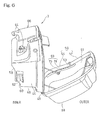
- the pannier 3 includes an inner side case 66 and an outer side case 68, and the inner and outer side case 66 and 68 open and close by means of the hinges 49 provided at a lower portion thereof.
- a packing (not shown) for waterproofing is provided at a contact portion between the inner side case 66 and the outer side case 68 over the entirety thereof.
- the pannier 3 shown in Fig. 2 has a rear surface 50 which is located such that an upper portion thereof hides the tail lamp 38 at the rear end of the motorcycle frame structure (rear frame) 2 when viewed from an outer lateral side.
- the rear surface 50 includes a first inclined surface 52 extending downward from an upper end 50a thereof so as to be inclined rearward, and a second inclined surface 54 extending downward from a lower end 52a of the first inclined surface 52 so as to be further greatly inclined rearward, in a standard state where a rider rides and a passenger does not ride. That is, the rear surface 50 of the pannier 3 is formed in a V shape opened rearward in a side view.
- the turn indicator 42 is exposed in a side view in a state where the pannier 3 is mounted to the motorcycle.
- a first inclination angle ⁇ 1 of the first inclined surface 52 relative to a vertical direction V is preferably set within the range of 10° to 30° and more preferably 20° to 26° in a side view.
- a second inclination angle ⁇ 2 of the second inclined surface 54 relative to the vertical direction V is preferably set within the range of 40° to 65° and more preferably 50° to 60° in a side view.
- An angle ⁇ of the V shape formed by the first inclined surface 52 and the second inclined surface 54 is preferably set within the range of 130° to 170° and more preferably 140° to 160° in a side view. In the present embodiment, the angle ⁇ is about 150°. If the angle ⁇ is less than 130°, it is difficult to ensure waterproofness of the pannier 3 as described later. If the angle ⁇ exceeds 170°, it is difficult to meet light distribution requirements described later. When the first and second inclination angles ⁇ 1 and ⁇ 2 of the inclined surfaces 52 and 54 are set within the above ranges, it is possible to easily ensure the angle ⁇ while the appearance of the pannier 3 is kept favorable.
- Fig. 3 is a rear view of the motorcycle. A sown in Fig. 3 , an outer end 3a, in a motorcycle widthwise, of each pannier 3 is located inward of an outer end 22a, in the motorcycle widthwise direction, of the rear-view mirror 22. Meanwhile, a portion of an inner end 3b, in the motorcycle widthwise direction, of each pannier 3 is located inward of the grab rail 36.
- a lower portion of the inner end 3b, in the motorcycle widthwise direction, of each pannier 3 is provided with a first recess portion 56 recessed from the inner side surface of the pannier 3, in order to ensure a clearance for the number plate 45.
- a second recess portion 58 ( Fig. 5 ) is formed for avoiding interference with the rear wheel 14, and a third recess portion 60 ( Fig. 5 ) is formed for avoiding interference with the chain 15 at the left side ( Fig. 3 ).
- the rear surface 50 of the pannier 3 extends rearward so as to be inclined laterally outward in a plan view.
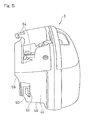
- Fig. 4 only the pannier 3 at the right side is illustrated, and the pannier 3 at the left side is omitted.
- Fig. 5 is a front view of the pannier 3 at the left side as viewed from front of a motorcycle body.
- the to-be-engaged portion 62 on the front surface 44 of the pannier 3 is formed in a U shape opened downward.
- two projection portions 64 are formed so as to project to the inner side of the motorcycle body and be aligned in a front-rear direction or longitudinal direction of the motorcycle body.
- the intersection angle ⁇ between the first inclined surface 52 and the second inclined surface 54 of the rear surface 50 of the pannier 3 shown in Fig. 2 is less than 180°.
- a base portion 53 of the V shape and a portion in the vicinity thereof easily deform when the pannier 3 is closed, whereby a seal member for waterproofing also deforms.
- a reinforcement portion 69 is provided on the inner surface of the outer side case 68 of the pannier 3 and in the vicinity of the base portion 53. Because of the reinforcement portion 69, the strength at and in the vicinity of the base portion 53 increases, and therefore, deformation does not occur and waterproofness can be ensured.
- the reinforcement portion 69 includes an inner wall 71 formed at the inner side of the pannier 3 with respect to a rear wall 51 forming the rear surface 50, and a plurality of rib plates 73 connecting the rear wall 51 and the inner wall 71.
- the configuration of the reinforcement portion 69 is not limited thereto, and, for example, the reinforcement portion 69 may be configured by increasing the thickness of the rear wall 51.
- pannier 3 Mounting the pannier 3 to the motorcycle frame structure FR will be described.
- the two projection portions 64 of the pannier 3 shown in Fig. 6 are inserted into engagement holes 70 of the grab rail 36 in Fig. 1 to be locked such that the projection portions 64 are prevented from coming out of the engagement holes 70.
- the engagement portion 29 of the step stay 28 is brought into engagement with the to-be-engaged portion 62 in Fig. 2 .
- the pannier 3 is supported by the rear frame 2 via the grab rail 36 and the step stay 28.
- a requirement for light distribution in the vertical direction of the tail lamp 38 and the turn indicator 42 is to be equal to or greater than 15° relative to the longitudinal (front-rear) axis of the motorcycle for the upper side and the lower side.
- an upper light distribution angle ⁇ 1 and a lower light distribution angle ⁇ 2 of the turn indicator 42 and an upper light distribution angle ⁇ 3 and a lower light distribution angle ⁇ 4 of the tail lamp 38 meet the requirement for light distribution.
- a requirement for light distribution in the right-left direction or motorcycle widthwise direction of the tail lamp 38 in Fig. 4 is to be equal or greater than 80° relative to the longitudinal (front-rear) axis of the motorcycle for the right and left sides.
- a requirement for light distribution in the motorcycle widthwise direction of the turn indicator 42 is to be equal to or greater than 80° relative to the longitudinal axis of the motorcycle for the outer side, and be equal to or greater than 20° relative to the longitudinal axis of the motorcycle for the inner side.
- an outer light distribution angle ⁇ 5 and an inner light distribution angle ⁇ 6 of the turn indicator 42 and an outer light distribution angle ⁇ 7 of the tail lamp 38 meet the requirements for light distribution.
- each of the right and left panniers 3 is configured to have a size which allows an L-size helmet H to be stored therein.
- the rear surface 50 of the pannier 3 is formed in a V shape opened rearward, and the turn indicator 42 is disposed at the opened portion in the side view.
- the rear surface 50 of the pannier 3 shown in Fig. 4 extends rearward so as to be inclined laterally outward.
- the pannier 103 may be greatly protruded rearward. However, if the pannier 103 is greatly protruded rearward, it is necessary to dispose each turn indicator 142 and the tail lamp 138 rearward at a position away from the rear frame 2 by using a bracket, as shown by broken lines 142 and 138 in Fig. 2 , in order to ensure sufficient light distribution of the turn indicator 42 and the tail lamp 38. If each turn indicator 142 and the tail lamp 138 are disposed away from the rear frame 2 by using the bracket as described above, the appearance of the motorcycle is impaired when the pannier 3 is dismounted.
- each turn indicator 142 and the tail lamp 138 are attached to the rear frame 2 in order to prevent the appearance of the motorcycle from being impaired, the operations of mounting and dismounting the pannier 3 become complicated.
- each pannier 3 is mounted to the grab rail 36.
- a portion of the inner end 3b, in the motorcycle widthwise direction, of each pannier 3 is disposed inward of the rear frame 2 in the motorcycle widthwise direction, and therefore, it is possible to increase the capacity of the pannier 3.
- the outer end 3a, in the motorcycle widthwise direction, of each pannier 3 is located inward of the outer end 22a, in the motorcycle widthwise direction, of the rear-view mirror 22.
- an increase in the overall dimension of the motorcycle in the motorcycle widthwise direction is suppressed. That is, it is possible to increase the capacity of each pannier 3 while suppressing an increase in the widthwise dimension of the motorcycle body.
- the reinforcement portion 69 is provided at the inside of the base portion 53 of the V shape in the pannier 3, the base portion 53 is unlikely to deform. As a result, the seal member for waterproofing does not deform, and thus, it is possible to ensure waterproofness.
- the first to third recess portions 56, 58, and 60 are formed in the pannier 3. Thus, it is possible to avoid interference between the number plate 45, the rear wheel 14, and the power transmission member 15.
- each turn indicator 42 is exposed from each pannier 3 and the tail lamp 38 is covered by each pannier 3 from the outer lateral side in a side view in the above-described embodiment, it suffices that sufficient light distribution of each turn indicator 42 and the tail lamp 38 is ensured, and both each turn indicator 42 and the tail lamp 38 may be exposed, or may not be exposed. Therefore, these are construed as included within the scope of the present invention.
Landscapes
- Engineering & Computer Science (AREA)
- Mechanical Engineering (AREA)
- Lighting Device Outwards From Vehicle And Optical Signal (AREA)
- Motorcycle And Bicycle Frame (AREA)
Abstract
Description
- This application is based on and claims Convention priority to
Japanese patent application No. 2013-100148, filed May 10, 2013 Japanese patent application No. 2013-125296, filed June 14, 2013 Japanese patent application No. 2013-180987, filed September 2, 2013 - The present invention relates to a motorcycle including a detachable pannier.
- A motorcycle has been known in which a pannier for accommodating a baggage is mountable to a rear portion of the motorcycle (e.g., Patent Document 1). The positions and shapes of the front surface, the upper surface, and the lower surface of the pannier are determined by a leg of a passenger, a passenger's seat, and a muffler, respectively. Thus, in order to increase the storage capacity of the pannier, it is necessary to extend rearward the rear surface of the pannier.
- [Patent Document 1]
JP Laid-open Patent Publication No. 2010-234913 - However, when the rear surface of the pannier is extended rearward, a tail lamp, a turn indicator, and the like (hereinafter, referred to as "rear portion lamps") are hidden behind the pannier when viewed from an outer lateral side, and as a result, the light distribution of the rear portion lamps may be insufficient. A motorcycle has been suggested in which, in order to ensure sufficient light distribution, rear portion lamps are supported by a motorcycle frame structure via a bracket extending rearward. In this case, however, when the pannier is dismounted, the bracket is exposed, whereby the appearance is poor.
- In view of the above-described problem, an object of the present invention is to provide a motorcycle in which a pannier having a large storage capacity is included but sufficient light distribution of a rear portion lamp is ensured even in a state where the pannier is mounted thereto and in which appearance thereof is not impaired even in a state where the pannier is dismounted.
- In order to achieve the above-described object, a motorcycle of the present invention includes detachable pannier. A rear surface of the pannier includes a first inclined surface extending downward from an upper end so as to be inclined rearward, and a second inclined surface extending downward from a lower end of the first inclined surface so as to be inclined rearward at an angle greater than the first inclined surface, and is formed in a V shape opened rearward in a side view by both of the first and second inclined surfaces, whereby a light distribution requirement that a tail lamp and a turn indicator can be seen from a rear side, is met in a state where the pannier is mounted. An angle α of the V shape formed by the first inclined surface and the second inclined surface is preferably set within the range of 130° to 170°. In addition, preferably, a first inclination angle β1 of the first inclined surface relative to a vertical direction is set within the range of 10° to 30°, and a second inclination angle β2 of the second inclined surface relative to the vertical direction is set within the range of 40° to 65°.
- According to this configuration, since the rear surface of the pannier extends downward so as to be inclined rearward, it is possible to increase the storage capacity of the pannier. In addition, since the rear surface of the pannier is formed in a V shape opened rearward, by disposing a rear portion lamp at the opened portion in the side view, it is possible to ensure sufficient light distribution of the rear portion lamp without disposing the rear portion lamp rearward via a bracket, even in a state where the pannier is mounted. Furthermore, since it is not necessary to dispose the rear portion lamp rearward via a bracket, the appearance is not impaired even in a state where the pannier is dismounted. If the angle α is less than 130°, it is difficult to ensure waterproofness of the pannier. If the angle α exceeds 170°, it is difficult to meet the light distribution requirement. Moreover, when the first inclination angle β1 is set within the range of 10° to 30° and the second inclination angle β2 is set within the range of 40° to 65°, it is possible to easily ensure the angle α in the range of 130° to 170° while the appearance of the pannier is kept favorable.
- In the present invention, preferably, the pannier is supported by a motorcycle frame structure via a grab rail to be held by a passenger, and at least a portion of an inner end, in a motorcycle widthwise direction, of the pannier is located inward of the grab rail. According to this configuration, since the portion of the inner end, in the motorcycle widthwise direction, of the pannier is located inward of the grab rail in the motorcycle widthwise direction, it is possible to increase the dimension, in the motorcycle widthwise direction, of the pannier, and therefore, the storage capacity of the pannier further increases.
- An outer end, in the motorcycle widthwise direction, of the pannier is preferably located inward of an outer end, in the motorcycle widthwise direction, of a rear-view mirror. According to this configuration, it is possible to suppress the dimension of the motorcycle in the motorcycle widthwise direction while the portion of the inner end, in the motorcycle widthwise direction, of the pannier is located inward of the grab rail in the motorcycle widthwise direction and the storage capacity of the pannier is increased.
- In the present invention, a reinforcement portion for preventing deformation is preferably provided at an inside of a base portion of the V shape in the pannier. If the rear surface of the pannier is formed in a V shape, when the pannier is closed, the base portion of the V shape easily deforms, and thus it is difficult to ensure waterproofness. However, according to this configuration, since the reinforcement portion is provided at the inside of the base portion of the V shape, the base portion is unlikely to deform, whereby waterproofness can be ensured.
- Any combination of at least two constructions, disclosed in the appended claims and/or the specification and/or the accompanying drawings should be construed as included within the scope of the present invention. In particular, any combination of two or more of the appended claims should be equally construed as included within the scope of the present invention.
- In any event, the present invention will become more clearly understood from the following description of preferred embodiments thereof, when taken in conjunction with the accompanying drawings. However, the embodiments and the drawings are given only for the purpose of illustration and explanation, and are not to be taken as limiting the scope of the present invention in any way whatsoever, which scope is to be determined by the appended claims. In the accompanying drawings, like reference numerals are used to denote like parts throughout the several views, and:
-
Fig. 1 is a side view showing a motorcycle according to a preferred embodiment of the present invention; -
Fig. 2 is a side view showing a rear portion of the motorcycle in a state where a pannier is mounted thereto; -
Fig. 3 is a rear view of the motorcycle; -
Fig. 4 is a plan view showing the rear portion of the motorcycle in a state where the pannier is mounted thereto; -
Fig. 5 is a front view of the pannier; and -
Fig. 6 is a perspective view showing a state where the pannier is opened. - Hereinafter, preferred embodiments of the present invention will be described with reference to the drawings. The terms "left side" and "right side" used in this specification are the left side and the right side relative to a driver maneuvering a vehicle to travel forwards.
-
Fig. 1 is a side view of a motorcycle according to a preferred embodiment of the present invention. The motorcycle is a vehicle to and from whicharticle storage panniers 3 are mountable and dismountable.Fig. 1 shows a state where the panniers are dismounted. A motorcycle frame structure FR for the motorcycle includes: amain frame 1 which forms a front half of the motorcycle frame structure FR; and arear frame 2 which is connected to a rear portion of themain frame 1 and forms a rear half of the motorcycle frame structure FR. A front wheel 6 is supported by a front end portion of themain frame 1 via a front fork 4. Aswingarm bracket 8 is provided at a lower portion of the rear end of themain frame 1. Aswingarm 12 is supported by theswingarm bracket 8 via apivot shaft 10 at a front end portion thereof so as to be able to swing in the vertical direction. Arear wheel 14 is supported by a rear end portion of theswingarm 12. - A combustion engine E is supported by a lower portion of the
main frame 1, and therear wheel 14 is driven by the engine E via a power transmission member 15 (Fig. 3 ) such as a chain. The engine E is, for example, a parallel multi-cylinder four-cycle engine. Exhaust gas of the engine E passes through anexhaust pipe 16 extending rearward via the front side and the lower side of the engine E, and is introduced intomufflers 18 connected thereto at both right and left sides of therear wheel 14. Thereafter, exhaust gas is discharged from themufflers 18 to the outside. Afairing 20 made of a resin is mounted to themain frame 1 to cover lateral sides of the engine E from front of the motorcycle frame structure FR. A rear-view mirror 22 is mounted to thefairing 20. The rear-view mirror 22 is provided at each of the right and left sides. - A rider's
seat 23 and a passenger'sseat 24 are supported by therear frame 2. A step stay 28 configured to support afoot step 26 which is a footrest for a passenger is mounted to therear frame 2, below the rider'sseat 23, and above themuffler 18. Thefoot step 26 and thestep stay 28 are provided at each of the right and left sides. - An
engagement portion 29 is formed at the rear end of the step stay 28 so as to extend rearward. Thepannier 3 is engaged with theengagement portion 29. By thestep stay 28, various rear parts are supported in addition to thestep 26 and thepannier 3. Specifically, a reservoir tank 34 for brake oil of a rear brake and themuffler 18 are supported by thestep stay 28. - A
grab rail 36 to be held by a passenger is mounted to therear frame 2 and below the passenger'sseat 24. Thegrab rail 36 is also provided at each of the right and left sides. Atail lamp 38 is mounted to a rear end portion of therear frame 2. Arear flap 40 is mounted to the lower surface of a rear portion of therear frame 2 so as to extend rearward and obliquely downward. A pair of right andleft turn indicators 42 and anumber plate 45 are mounted to therear flap 40. -
Fig. 2 is a side view showing a rear portion of the motorcycle in a state where thepannier 3 is mounted thereto. Thepannier 3 is supported at a front portion thereof by thestep stay 28 in a state where an upper portion thereof is supported by therear frame 2 via thegrab rail 36. A supporting structure for thepannier 3 will be described in detail later. - The
pannier 3 of the present embodiment is made of ABS. Left andright side paniers pannier 3 is not limited thereto. Thepannier 3 has afront surface 44 which is shaped along a leg L of the passenger. A to-be-engaged portion 62 is formed on thefront surface 44 of thepannier 3 so as to project frontward, and theengagement portion 29 is engaged with the to-be-engaged portion 62. Thepannier 3 has anupper surface 46 which is located below anupper surface 24a of the passenger'sseat 24. Thepannier 3 has alower surface 48 that is located at a position at which exhaust gas G from themuffler 18 does not directly hit thelower surface 48.Hinges 49 are provided on thelower surface 48 of thepannier 3. - That is, as shown in
Fig. 6 , thepannier 3 includes aninner side case 66 and anouter side case 68, and the inner andouter side case hinges 49 provided at a lower portion thereof. A packing (not shown) for waterproofing is provided at a contact portion between theinner side case 66 and theouter side case 68 over the entirety thereof. - The
pannier 3 shown inFig. 2 has arear surface 50 which is located such that an upper portion thereof hides thetail lamp 38 at the rear end of the motorcycle frame structure (rear frame) 2 when viewed from an outer lateral side. Therear surface 50 includes a firstinclined surface 52 extending downward from an upper end 50a thereof so as to be inclined rearward, and a secondinclined surface 54 extending downward from a lower end 52a of the firstinclined surface 52 so as to be further greatly inclined rearward, in a standard state where a rider rides and a passenger does not ride. That is, therear surface 50 of thepannier 3 is formed in a V shape opened rearward in a side view. - In the present embodiment, the
turn indicator 42 is exposed in a side view in a state where thepannier 3 is mounted to the motorcycle. A first inclination angle β1 of the firstinclined surface 52 relative to a vertical direction V is preferably set within the range of 10° to 30° and more preferably 20° to 26° in a side view. A second inclination angle β2 of the secondinclined surface 54 relative to the vertical direction V is preferably set within the range of 40° to 65° and more preferably 50° to 60° in a side view. - An angle α of the V shape formed by the first
inclined surface 52 and the secondinclined surface 54 is preferably set within the range of 130° to 170° and more preferably 140° to 160° in a side view. In the present embodiment, the angle α is about 150°. If the angle α is less than 130°, it is difficult to ensure waterproofness of thepannier 3 as described later. If the angle α exceeds 170°, it is difficult to meet light distribution requirements described later. When the first and second inclination angles β1 and β2 of theinclined surfaces pannier 3 is kept favorable. -
Fig. 3 is a rear view of the motorcycle. A sown inFig. 3 , anouter end 3a, in a motorcycle widthwise, of eachpannier 3 is located inward of anouter end 22a, in the motorcycle widthwise direction, of the rear-view mirror 22. Meanwhile, a portion of aninner end 3b, in the motorcycle widthwise direction, of eachpannier 3 is located inward of thegrab rail 36. - A lower portion of the
inner end 3b, in the motorcycle widthwise direction, of eachpannier 3 is provided with afirst recess portion 56 recessed from the inner side surface of thepannier 3, in order to ensure a clearance for thenumber plate 45. In addition, on thelower surface 48 of eachpannier 3, a second recess portion 58 (Fig. 5 ) is formed for avoiding interference with therear wheel 14, and a third recess portion 60 (Fig. 5 ) is formed for avoiding interference with thechain 15 at the left side (Fig. 3 ). - As shown in
Fig. 4 , therear surface 50 of thepannier 3 extends rearward so as to be inclined laterally outward in a plan view. InFig. 4 , only thepannier 3 at the right side is illustrated, and thepannier 3 at the left side is omitted. -
Fig. 5 is a front view of thepannier 3 at the left side as viewed from front of a motorcycle body. The to-be-engaged portion 62 on thefront surface 44 of thepannier 3 is formed in a U shape opened downward. On the inner surface of an upper portion of thepannier 3, twoprojection portions 64 are formed so as to project to the inner side of the motorcycle body and be aligned in a front-rear direction or longitudinal direction of the motorcycle body. - The intersection angle α between the first
inclined surface 52 and the secondinclined surface 54 of therear surface 50 of thepannier 3 shown inFig. 2 is less than 180°. Thus, abase portion 53 of the V shape and a portion in the vicinity thereof easily deform when thepannier 3 is closed, whereby a seal member for waterproofing also deforms. Thus, it is difficult to ensure waterproofness. However, in the present embodiment, as shown inFig. 6 , areinforcement portion 69 is provided on the inner surface of theouter side case 68 of thepannier 3 and in the vicinity of thebase portion 53. Because of thereinforcement portion 69, the strength at and in the vicinity of thebase portion 53 increases, and therefore, deformation does not occur and waterproofness can be ensured. - The
reinforcement portion 69 includes aninner wall 71 formed at the inner side of thepannier 3 with respect to arear wall 51 forming therear surface 50, and a plurality ofrib plates 73 connecting therear wall 51 and theinner wall 71. The configuration of thereinforcement portion 69 is not limited thereto, and, for example, thereinforcement portion 69 may be configured by increasing the thickness of therear wall 51. - Mounting the
pannier 3 to the motorcycle frame structure FR will be described. The twoprojection portions 64 of thepannier 3 shown inFig. 6 are inserted into engagement holes 70 of thegrab rail 36 inFig. 1 to be locked such that theprojection portions 64 are prevented from coming out of the engagement holes 70. In this state, theengagement portion 29 of thestep stay 28 is brought into engagement with the to-be-engaged portion 62 inFig. 2 . Thus, thepannier 3 is supported by therear frame 2 via thegrab rail 36 and thestep stay 28. - A requirement for light distribution in the vertical direction of the
tail lamp 38 and theturn indicator 42 is to be equal to or greater than 15° relative to the longitudinal (front-rear) axis of the motorcycle for the upper side and the lower side. In the present embodiment, in a state where thepannier 3 is mounted to the motorcycle body, an upper light distribution angle θ1 and a lower light distribution angle θ2 of theturn indicator 42 and an upper light distribution angle θ3 and a lower light distribution angle θ4 of thetail lamp 38 meet the requirement for light distribution. - A requirement for light distribution in the right-left direction or motorcycle widthwise direction of the
tail lamp 38 inFig. 4 is to be equal or greater than 80° relative to the longitudinal (front-rear) axis of the motorcycle for the right and left sides. A requirement for light distribution in the motorcycle widthwise direction of theturn indicator 42 is to be equal to or greater than 80° relative to the longitudinal axis of the motorcycle for the outer side, and be equal to or greater than 20° relative to the longitudinal axis of the motorcycle for the inner side. In the present embodiment, in a state where thepannier 3 is mounted to the motorcycle body, an outer light distribution angle θ5 and an inner light distribution angle θ6 of theturn indicator 42 and an outer light distribution angle θ7 of thetail lamp 38 meet the requirements for light distribution. - In the above-described configuration, as shown in
Fig. 2 , the rear end of theupper surface 46 of thepannier 3 extends to the rear end of therear frame 2, and therear surface 50 of thepannier 3 extends rearward so as to be inclined downward. Thus, it is possible to increase the storage capacity of thepannier 3. Specifically, each of the right and leftpanniers 3 is configured to have a size which allows an L-size helmet H to be stored therein. - The
rear surface 50 of thepannier 3 is formed in a V shape opened rearward, and theturn indicator 42 is disposed at the opened portion in the side view. Thus, as shown inFig. 4 , even in a state where thepannier 3 is mounted to the motorcycle body, it is possible to ensure sufficient light distribution of theturn indicator 42 without disposing theturn indicator 42 rearward via a bracket. - The
rear surface 50 of thepannier 3 shown inFig. 4 extends rearward so as to be inclined laterally outward. Thus, even in a state where thepannier 3 is mounted to the motorcycle body, it is also possible to ensure sufficient light distribution of thetail lamp 38 without disposing thetail lamp 38 rearward via a bracket. - Only in order to increase the capacity of the
pannier 3, as shown by abroken line 103 inFig. 2 , thepannier 103 may be greatly protruded rearward. However, if thepannier 103 is greatly protruded rearward, it is necessary to dispose eachturn indicator 142 and thetail lamp 138 rearward at a position away from therear frame 2 by using a bracket, as shown bybroken lines Fig. 2 , in order to ensure sufficient light distribution of theturn indicator 42 and thetail lamp 38. If eachturn indicator 142 and thetail lamp 138 are disposed away from therear frame 2 by using the bracket as described above, the appearance of the motorcycle is impaired when thepannier 3 is dismounted. If, in dismounting thepannier 3, the bracket is also detached, and then, eachturn indicator 142 and thetail lamp 138 are attached to therear frame 2 in order to prevent the appearance of the motorcycle from being impaired, the operations of mounting and dismounting thepannier 3 become complicated. - In the present embodiment, since it is not necessary to dispose each
turn indicator 42 and thetail lamp 38 rearward via a bracket as described above, the appearance is not impaired even in a state where thepannier 3 is dismounted. In addition, in dismounting thepannier 3 from the motorcycle body, thepannier 3 does not hit a bracket, and it is not necessary to detach a bracket. Thus, it is easy to mount and dismount thepannier 3. - As shown in
Fig. 3 , eachpannier 3 is mounted to thegrab rail 36. Thus, a portion of theinner end 3b, in the motorcycle widthwise direction, of eachpannier 3 is disposed inward of therear frame 2 in the motorcycle widthwise direction, and therefore, it is possible to increase the capacity of thepannier 3. Meanwhile, theouter end 3a, in the motorcycle widthwise direction, of eachpannier 3 is located inward of theouter end 22a, in the motorcycle widthwise direction, of the rear-view mirror 22. Thus, an increase in the overall dimension of the motorcycle in the motorcycle widthwise direction is suppressed. That is, it is possible to increase the capacity of eachpannier 3 while suppressing an increase in the widthwise dimension of the motorcycle body. - Since the
reinforcement portion 69 is provided at the inside of thebase portion 53 of the V shape in thepannier 3, thebase portion 53 is unlikely to deform. As a result, the seal member for waterproofing does not deform, and thus, it is possible to ensure waterproofness. - The first to
third recess portions pannier 3. Thus, it is possible to avoid interference between thenumber plate 45, therear wheel 14, and thepower transmission member 15. - The present invention is not limited to the above-described embodiment, and various additions, changes, or deletions can be made without departing from the gist of the present invention. For example, although each
turn indicator 42 is exposed from eachpannier 3 and thetail lamp 38 is covered by eachpannier 3 from the outer lateral side in a side view in the above-described embodiment, it suffices that sufficient light distribution of eachturn indicator 42 and thetail lamp 38 is ensured, and both eachturn indicator 42 and thetail lamp 38 may be exposed, or may not be exposed. Therefore, these are construed as included within the scope of the present invention. -
- 3 ···· pannier
- 22 ···· rear-view mirror
- 36 ···· grab rail
- 38 ···· tail lamp (rear portion lamp)
- 42 ···· turn indicator (rear portion lamp)
- 50 ···· rear surface of pannier
- 52 ···· first inclined surface
- 53 ···· base portion of V shape
- 54 ···· second inclined surface
- 69 ···· reinforcement portion
- FR ···· motorcycle frame structure
Claims (6)
- A motorcycle comprising a detachable pannier, wherein
a rear surface of the pannier includes a first inclined surface extending downward from an upper end so as to be inclined rearward, and a second inclined surface extending downward from a lower end of the first inclined surface so as to be inclined rearward at an angle greater than the first inclined surface, and is formed in a V shape opened rearward in a side view by both of the first and second inclined surfaces, whereby
a light distribution requirement that a tail lamp and a turn indicator can be seen from a rear side, is met in a state where the pannier is mounted. - The motorcycle as claimed in claim 1, wherein
the pannier is supported by a motorcycle frame structure via a grab rail to be held by a passenger, and
at least a portion of an inner end, in a motorcycle widthwise direction, of the pannier is located inward of the grab rail. - The motorcycle as claimed in claim 2, wherein an outer end, in the motorcycle widthwise direction, of the pannier is located inward of an outer end, in the motorcycle widthwise direction, of a rear-view mirror.
- The motorcycle as claimed in any one of claims 1 to 3, wherein a reinforcement portion for preventing deformation is provided at an inside of a base portion of the V shape in the pannier.
- The motorcycle as claimed in any one of claims 1 to 4, wherein an angle α of the V shape formed by the first inclined surface and the second inclined surface is set within the range of 130° to 170°.
- The motorcycle as claimed in claim 5, wherein a first inclination angle β1 of the first inclined surface relative to a vertical direction is set within the range of 10° to 30°, and a second inclination angle β2 of the second inclined surface relative to the vertical direction is set within the range of 40° to 65°.
Applications Claiming Priority (4)
| Application Number | Priority Date | Filing Date | Title |
|---|---|---|---|
| JP2013100148 | 2013-05-10 | ||
| JP2013125296A JP6076842B2 (en) | 2013-06-14 | 2013-06-14 | Support structure for rear parts of motorcycle |
| JP2013180987A JP6118216B2 (en) | 2013-09-02 | 2013-09-02 | Motorcycle |
| PCT/JP2014/060867 WO2014181651A1 (en) | 2013-05-10 | 2014-04-16 | Motorcycle |
Publications (3)
| Publication Number | Publication Date |
|---|---|
| EP2995538A1 true EP2995538A1 (en) | 2016-03-16 |
| EP2995538A4 EP2995538A4 (en) | 2016-12-21 |
| EP2995538B1 EP2995538B1 (en) | 2018-07-11 |
Family
ID=51867133
Family Applications (1)
| Application Number | Title | Priority Date | Filing Date |
|---|---|---|---|
| EP14794712.1A Active EP2995538B1 (en) | 2013-05-10 | 2014-04-16 | Motorcycle |
Country Status (4)
| Country | Link |
|---|---|
| US (1) | US9409615B2 (en) |
| EP (1) | EP2995538B1 (en) |
| CN (1) | CN105189269B (en) |
| WO (1) | WO2014181651A1 (en) |
Families Citing this family (6)
| Publication number | Priority date | Publication date | Assignee | Title |
|---|---|---|---|---|
| DE102013220335A1 (en) * | 2013-10-09 | 2015-04-09 | Bayerische Motoren Werke Aktiengesellschaft | Luggage suitcase |
| JP2016032949A (en) * | 2014-07-30 | 2016-03-10 | 本田技研工業株式会社 | Step structure of saddle-riding type vehicle |
| JP6141924B2 (en) * | 2015-08-07 | 2017-06-07 | 本田技研工業株式会社 | Step structure in motorcycles |
| EP3403907B1 (en) | 2016-02-05 | 2021-04-07 | Honda Motor Co., Ltd. | Saddle-type vehicle |
| WO2022209868A1 (en) * | 2021-03-30 | 2022-10-06 | 本田技研工業株式会社 | Vehicle, vehicle structure, and component for vehicle |
| JP2025091857A (en) * | 2023-12-08 | 2025-06-19 | ヤマハ発動機株式会社 | Saddle-type vehicle |
Family Cites Families (25)
| Publication number | Priority date | Publication date | Assignee | Title |
|---|---|---|---|---|
| GB446331A (en) * | 1935-11-25 | 1936-04-28 | Max Kyburz | Improvements in and relating to luggage-receptacles for motor cycles |
| US4163513A (en) * | 1977-05-16 | 1979-08-07 | Ralph Kramer | Motorcycle saddlebox |
| JPS6018469A (en) * | 1983-07-12 | 1985-01-30 | ヤマハ発動機株式会社 | Trunk for motorcycle |
| DE3612311A1 (en) * | 1986-04-11 | 1987-12-17 | Krauser Kraftfahrzeug Zubehoer | ONE-PIECE BRACKET FIXABLE TO A MOTORCYCLE FRAME |
| JPH033114Y2 (en) * | 1986-11-15 | 1991-01-28 | ||
| JPH033114A (en) | 1989-05-31 | 1991-01-09 | Sekisui Chem Co Ltd | Magnetic disk substrate |
| USD445398S1 (en) * | 2000-12-15 | 2001-07-24 | Michael Hanagan | Pair of motorcycle saddlebags |
| USD497341S1 (en) * | 2003-04-16 | 2004-10-19 | Corbin Pacific, Inc. | Pair of motorcycle saddlebags |
| US7150382B2 (en) * | 2003-12-09 | 2006-12-19 | Zickefoose Mark S | Attachment to motorcycle to safely transport musical instruments |
| US20050217599A1 (en) * | 2004-03-31 | 2005-10-06 | Michael Varner | Saddlebox pet carrier product |
| US20060163302A1 (en) * | 2005-01-21 | 2006-07-27 | Harley-Davidson Motor Company Group, Inc. | Motorcycle saddlebag mounting system |
| US7883136B2 (en) * | 2007-01-17 | 2011-02-08 | Polaris Industries Inc. | Two-wheeled vehicle |
| JP2008285065A (en) * | 2007-05-18 | 2008-11-27 | Yamaha Motor Engineering Kk | Carrier device for motorcycle |
| JP5091804B2 (en) * | 2008-08-22 | 2012-12-05 | 本田技研工業株式会社 | Saddle bag mounting structure for motorcycles |
| CN201325516Y (en) * | 2008-12-22 | 2009-10-14 | 重庆宗申技术开发研究有限公司 | Side box of motorbike |
| JP5328448B2 (en) | 2009-03-30 | 2013-10-30 | 本田技研工業株式会社 | Motorcycle |
| CN201419753Y (en) * | 2009-05-31 | 2010-03-10 | 重庆宗申技术开发研究有限公司 | Motorcycle side box mounting structure |
| JP2011201515A (en) * | 2010-03-26 | 2011-10-13 | Honda Motor Co Ltd | Saddle bag and motorcycle with the same |
| JP5520733B2 (en) * | 2010-07-28 | 2014-06-11 | 本田技研工業株式会社 | Saddle riding |
| CN201980352U (en) * | 2011-02-25 | 2011-09-21 | 重庆市公安局 | Patrol motorcycle |
| JP5722184B2 (en) * | 2011-09-29 | 2015-05-20 | 本田技研工業株式会社 | Pannier case mounting structure for saddle-ride type vehicles |
| EP2995539B1 (en) * | 2013-05-10 | 2019-06-12 | Kawasaki Jukogyo Kabushiki Kaisha | Supporting structure for rear parts of a motorcycle |
| CN105189966B (en) * | 2013-05-10 | 2018-07-24 | 川崎重工业株式会社 | Exhaust device for automatic two-wheeler |
| USD743325S1 (en) * | 2013-09-04 | 2015-11-17 | Kawasaki Jukogyo Kabushiki Kaisha | Pannier for motorcycles |
| US9628482B2 (en) * | 2013-10-31 | 2017-04-18 | Cellco Partnership | Mobile based login via wireless credential transfer |
-
2014
- 2014-04-16 CN CN201480026290.5A patent/CN105189269B/en active Active
- 2014-04-16 EP EP14794712.1A patent/EP2995538B1/en active Active
- 2014-04-16 WO PCT/JP2014/060867 patent/WO2014181651A1/en not_active Ceased
-
2015
- 2015-10-30 US US14/928,847 patent/US9409615B2/en active Active
Also Published As
| Publication number | Publication date |
|---|---|
| US9409615B2 (en) | 2016-08-09 |
| CN105189269A (en) | 2015-12-23 |
| EP2995538A4 (en) | 2016-12-21 |
| EP2995538B1 (en) | 2018-07-11 |
| WO2014181651A1 (en) | 2014-11-13 |
| US20160052581A1 (en) | 2016-02-25 |
| CN105189269B (en) | 2018-02-06 |
Similar Documents
| Publication | Publication Date | Title |
|---|---|---|
| US9409615B2 (en) | Motorcycle | |
| US8845154B2 (en) | Motorcycle | |
| EP2213559B1 (en) | Rear fender structure for motorcycle and motorcycle | |
| US7523801B2 (en) | Motorcycle with inclination sensor | |
| US20110204613A1 (en) | Saddle-ride type vehicle | |
| EP2128007B1 (en) | Motorcycle | |
| US9004224B2 (en) | Exhaust system of saddle-ride type vehicle | |
| US8814244B2 (en) | Accommodation structure for saddle type vehicle | |
| EP2468613B1 (en) | Vehicle handlebar support structure | |
| JP5727874B2 (en) | Front structure of saddle-ride type vehicle | |
| US6860359B2 (en) | Rear structure of motorcycle | |
| US9434436B1 (en) | Rear structure for saddle-ride type vehicle | |
| US6857497B2 (en) | Rear structure of motorcycle | |
| US20150259019A1 (en) | Saddled vehicle | |
| JP5460526B2 (en) | Front structure of motorcycle | |
| KR20140038314A (en) | Saddle riding type vehicle | |
| JP5423154B2 (en) | Motorcycle frame cover mounting structure | |
| JP6083600B2 (en) | Arrangement structure of communication unit in saddle-ride type vehicle | |
| CN102785728B (en) | Saddle type vehicle | |
| JP6118216B2 (en) | Motorcycle | |
| CN101801774B (en) | Straddle riding type vehicle | |
| JP2014240255A (en) | Saddle-riding type vehicle | |
| JP5597601B2 (en) | Saddle riding | |
| JP2011148452A (en) | Rear structure of saddle riding type vehicle | |
| EP2878523B1 (en) | Straddle-type vehicle |
Legal Events
| Date | Code | Title | Description |
|---|---|---|---|
| PUAI | Public reference made under article 153(3) epc to a published international application that has entered the european phase |
Free format text: ORIGINAL CODE: 0009012 |
|
| 17P | Request for examination filed |
Effective date: 20151118 |
|
| AK | Designated contracting states |
Kind code of ref document: A1 Designated state(s): AL AT BE BG CH CY CZ DE DK EE ES FI FR GB GR HR HU IE IS IT LI LT LU LV MC MK MT NL NO PL PT RO RS SE SI SK SM TR |
|
| AX | Request for extension of the european patent |
Extension state: BA ME |
|
| DAX | Request for extension of the european patent (deleted) | ||
| A4 | Supplementary search report drawn up and despatched |
Effective date: 20161117 |
|
| RIC1 | Information provided on ipc code assigned before grant |
Ipc: B62J 6/00 20060101ALI20161111BHEP Ipc: B62J 6/04 20060101ALI20161111BHEP Ipc: B62J 9/00 20060101AFI20161111BHEP Ipc: B62J 1/28 20060101ALI20161111BHEP |
|
| STAA | Information on the status of an ep patent application or granted ep patent |
Free format text: STATUS: EXAMINATION IS IN PROGRESS |
|
| 17Q | First examination report despatched |
Effective date: 20170918 |
|
| GRAP | Despatch of communication of intention to grant a patent |
Free format text: ORIGINAL CODE: EPIDOSNIGR1 |
|
| STAA | Information on the status of an ep patent application or granted ep patent |
Free format text: STATUS: GRANT OF PATENT IS INTENDED |
|
| INTG | Intention to grant announced |
Effective date: 20180321 |
|
| GRAS | Grant fee paid |
Free format text: ORIGINAL CODE: EPIDOSNIGR3 |
|
| GRAA | (expected) grant |
Free format text: ORIGINAL CODE: 0009210 |
|
| STAA | Information on the status of an ep patent application or granted ep patent |
Free format text: STATUS: THE PATENT HAS BEEN GRANTED |
|
| AK | Designated contracting states |
Kind code of ref document: B1 Designated state(s): AL AT BE BG CH CY CZ DE DK EE ES FI FR GB GR HR HU IE IS IT LI LT LU LV MC MK MT NL NO PL PT RO RS SE SI SK SM TR |
|
| REG | Reference to a national code |
Ref country code: GB Ref legal event code: FG4D |
|
| REG | Reference to a national code |
Ref country code: CH Ref legal event code: EP |
|
| REG | Reference to a national code |
Ref country code: AT Ref legal event code: REF Ref document number: 1016588 Country of ref document: AT Kind code of ref document: T Effective date: 20180715 |
|
| REG | Reference to a national code |
Ref country code: IE Ref legal event code: FG4D |
|
| REG | Reference to a national code |
Ref country code: DE Ref legal event code: R096 Ref document number: 602014028395 Country of ref document: DE |
|
| REG | Reference to a national code |
Ref country code: NL Ref legal event code: MP Effective date: 20180711 |
|
| REG | Reference to a national code |
Ref country code: LT Ref legal event code: MG4D |
|
| REG | Reference to a national code |
Ref country code: AT Ref legal event code: MK05 Ref document number: 1016588 Country of ref document: AT Kind code of ref document: T Effective date: 20180711 |
|
| PG25 | Lapsed in a contracting state [announced via postgrant information from national office to epo] |
Ref country code: NL Free format text: LAPSE BECAUSE OF FAILURE TO SUBMIT A TRANSLATION OF THE DESCRIPTION OR TO PAY THE FEE WITHIN THE PRESCRIBED TIME-LIMIT Effective date: 20180711 |
|
| PG25 | Lapsed in a contracting state [announced via postgrant information from national office to epo] |
Ref country code: FI Free format text: LAPSE BECAUSE OF FAILURE TO SUBMIT A TRANSLATION OF THE DESCRIPTION OR TO PAY THE FEE WITHIN THE PRESCRIBED TIME-LIMIT Effective date: 20180711 Ref country code: IS Free format text: LAPSE BECAUSE OF FAILURE TO SUBMIT A TRANSLATION OF THE DESCRIPTION OR TO PAY THE FEE WITHIN THE PRESCRIBED TIME-LIMIT Effective date: 20181111 Ref country code: PL Free format text: LAPSE BECAUSE OF FAILURE TO SUBMIT A TRANSLATION OF THE DESCRIPTION OR TO PAY THE FEE WITHIN THE PRESCRIBED TIME-LIMIT Effective date: 20180711 Ref country code: AT Free format text: LAPSE BECAUSE OF FAILURE TO SUBMIT A TRANSLATION OF THE DESCRIPTION OR TO PAY THE FEE WITHIN THE PRESCRIBED TIME-LIMIT Effective date: 20180711 Ref country code: LT Free format text: LAPSE BECAUSE OF FAILURE TO SUBMIT A TRANSLATION OF THE DESCRIPTION OR TO PAY THE FEE WITHIN THE PRESCRIBED TIME-LIMIT Effective date: 20180711 Ref country code: BG Free format text: LAPSE BECAUSE OF FAILURE TO SUBMIT A TRANSLATION OF THE DESCRIPTION OR TO PAY THE FEE WITHIN THE PRESCRIBED TIME-LIMIT Effective date: 20181011 Ref country code: GR Free format text: LAPSE BECAUSE OF FAILURE TO SUBMIT A TRANSLATION OF THE DESCRIPTION OR TO PAY THE FEE WITHIN THE PRESCRIBED TIME-LIMIT Effective date: 20181012 Ref country code: NO Free format text: LAPSE BECAUSE OF FAILURE TO SUBMIT A TRANSLATION OF THE DESCRIPTION OR TO PAY THE FEE WITHIN THE PRESCRIBED TIME-LIMIT Effective date: 20181011 Ref country code: RS Free format text: LAPSE BECAUSE OF FAILURE TO SUBMIT A TRANSLATION OF THE DESCRIPTION OR TO PAY THE FEE WITHIN THE PRESCRIBED TIME-LIMIT Effective date: 20180711 Ref country code: SE Free format text: LAPSE BECAUSE OF FAILURE TO SUBMIT A TRANSLATION OF THE DESCRIPTION OR TO PAY THE FEE WITHIN THE PRESCRIBED TIME-LIMIT Effective date: 20180711 |
|
| PG25 | Lapsed in a contracting state [announced via postgrant information from national office to epo] |
Ref country code: AL Free format text: LAPSE BECAUSE OF FAILURE TO SUBMIT A TRANSLATION OF THE DESCRIPTION OR TO PAY THE FEE WITHIN THE PRESCRIBED TIME-LIMIT Effective date: 20180711 Ref country code: ES Free format text: LAPSE BECAUSE OF FAILURE TO SUBMIT A TRANSLATION OF THE DESCRIPTION OR TO PAY THE FEE WITHIN THE PRESCRIBED TIME-LIMIT Effective date: 20180711 Ref country code: LV Free format text: LAPSE BECAUSE OF FAILURE TO SUBMIT A TRANSLATION OF THE DESCRIPTION OR TO PAY THE FEE WITHIN THE PRESCRIBED TIME-LIMIT Effective date: 20180711 Ref country code: HR Free format text: LAPSE BECAUSE OF FAILURE TO SUBMIT A TRANSLATION OF THE DESCRIPTION OR TO PAY THE FEE WITHIN THE PRESCRIBED TIME-LIMIT Effective date: 20180711 |
|
| REG | Reference to a national code |
Ref country code: DE Ref legal event code: R097 Ref document number: 602014028395 Country of ref document: DE |
|
| PG25 | Lapsed in a contracting state [announced via postgrant information from national office to epo] |
Ref country code: IT Free format text: LAPSE BECAUSE OF FAILURE TO SUBMIT A TRANSLATION OF THE DESCRIPTION OR TO PAY THE FEE WITHIN THE PRESCRIBED TIME-LIMIT Effective date: 20180711 Ref country code: EE Free format text: LAPSE BECAUSE OF FAILURE TO SUBMIT A TRANSLATION OF THE DESCRIPTION OR TO PAY THE FEE WITHIN THE PRESCRIBED TIME-LIMIT Effective date: 20180711 Ref country code: RO Free format text: LAPSE BECAUSE OF FAILURE TO SUBMIT A TRANSLATION OF THE DESCRIPTION OR TO PAY THE FEE WITHIN THE PRESCRIBED TIME-LIMIT Effective date: 20180711 Ref country code: CZ Free format text: LAPSE BECAUSE OF FAILURE TO SUBMIT A TRANSLATION OF THE DESCRIPTION OR TO PAY THE FEE WITHIN THE PRESCRIBED TIME-LIMIT Effective date: 20180711 |
|
| PLBE | No opposition filed within time limit |
Free format text: ORIGINAL CODE: 0009261 |
|
| STAA | Information on the status of an ep patent application or granted ep patent |
Free format text: STATUS: NO OPPOSITION FILED WITHIN TIME LIMIT |
|
| PG25 | Lapsed in a contracting state [announced via postgrant information from national office to epo] |
Ref country code: DK Free format text: LAPSE BECAUSE OF FAILURE TO SUBMIT A TRANSLATION OF THE DESCRIPTION OR TO PAY THE FEE WITHIN THE PRESCRIBED TIME-LIMIT Effective date: 20180711 Ref country code: SK Free format text: LAPSE BECAUSE OF FAILURE TO SUBMIT A TRANSLATION OF THE DESCRIPTION OR TO PAY THE FEE WITHIN THE PRESCRIBED TIME-LIMIT Effective date: 20180711 Ref country code: SM Free format text: LAPSE BECAUSE OF FAILURE TO SUBMIT A TRANSLATION OF THE DESCRIPTION OR TO PAY THE FEE WITHIN THE PRESCRIBED TIME-LIMIT Effective date: 20180711 |
|
| 26N | No opposition filed |
Effective date: 20190412 |
|
| PG25 | Lapsed in a contracting state [announced via postgrant information from national office to epo] |
Ref country code: SI Free format text: LAPSE BECAUSE OF FAILURE TO SUBMIT A TRANSLATION OF THE DESCRIPTION OR TO PAY THE FEE WITHIN THE PRESCRIBED TIME-LIMIT Effective date: 20180711 |
|
| REG | Reference to a national code |
Ref country code: CH Ref legal event code: PL |
|
| REG | Reference to a national code |
Ref country code: BE Ref legal event code: MM Effective date: 20190430 |
|
| GBPC | Gb: european patent ceased through non-payment of renewal fee |
Effective date: 20190416 |
|
| PG25 | Lapsed in a contracting state [announced via postgrant information from national office to epo] |
Ref country code: LU Free format text: LAPSE BECAUSE OF NON-PAYMENT OF DUE FEES Effective date: 20190416 Ref country code: MC Free format text: LAPSE BECAUSE OF FAILURE TO SUBMIT A TRANSLATION OF THE DESCRIPTION OR TO PAY THE FEE WITHIN THE PRESCRIBED TIME-LIMIT Effective date: 20180711 |
|
| PG25 | Lapsed in a contracting state [announced via postgrant information from national office to epo] |
Ref country code: GB Free format text: LAPSE BECAUSE OF NON-PAYMENT OF DUE FEES Effective date: 20190416 Ref country code: CH Free format text: LAPSE BECAUSE OF NON-PAYMENT OF DUE FEES Effective date: 20190430 Ref country code: LI Free format text: LAPSE BECAUSE OF NON-PAYMENT OF DUE FEES Effective date: 20190430 |
|
| PG25 | Lapsed in a contracting state [announced via postgrant information from national office to epo] |
Ref country code: BE Free format text: LAPSE BECAUSE OF NON-PAYMENT OF DUE FEES Effective date: 20190430 |
|
| PG25 | Lapsed in a contracting state [announced via postgrant information from national office to epo] |
Ref country code: TR Free format text: LAPSE BECAUSE OF FAILURE TO SUBMIT A TRANSLATION OF THE DESCRIPTION OR TO PAY THE FEE WITHIN THE PRESCRIBED TIME-LIMIT Effective date: 20180711 |
|
| PG25 | Lapsed in a contracting state [announced via postgrant information from national office to epo] |
Ref country code: IE Free format text: LAPSE BECAUSE OF NON-PAYMENT OF DUE FEES Effective date: 20190416 |
|
| PG25 | Lapsed in a contracting state [announced via postgrant information from national office to epo] |
Ref country code: PT Free format text: LAPSE BECAUSE OF FAILURE TO SUBMIT A TRANSLATION OF THE DESCRIPTION OR TO PAY THE FEE WITHIN THE PRESCRIBED TIME-LIMIT Effective date: 20181111 |
|
| PGFP | Annual fee paid to national office [announced via postgrant information from national office to epo] |
Ref country code: FR Payment date: 20210310 Year of fee payment: 8 |
|
| PG25 | Lapsed in a contracting state [announced via postgrant information from national office to epo] |
Ref country code: CY Free format text: LAPSE BECAUSE OF FAILURE TO SUBMIT A TRANSLATION OF THE DESCRIPTION OR TO PAY THE FEE WITHIN THE PRESCRIBED TIME-LIMIT Effective date: 20180711 |
|
| PG25 | Lapsed in a contracting state [announced via postgrant information from national office to epo] |
Ref country code: HU Free format text: LAPSE BECAUSE OF FAILURE TO SUBMIT A TRANSLATION OF THE DESCRIPTION OR TO PAY THE FEE WITHIN THE PRESCRIBED TIME-LIMIT; INVALID AB INITIO Effective date: 20140416 Ref country code: MT Free format text: LAPSE BECAUSE OF FAILURE TO SUBMIT A TRANSLATION OF THE DESCRIPTION OR TO PAY THE FEE WITHIN THE PRESCRIBED TIME-LIMIT Effective date: 20180711 |
|
| REG | Reference to a national code |
Ref country code: DE Ref legal event code: R081 Ref document number: 602014028395 Country of ref document: DE Owner name: KAWASAKI MOTORS, LTD., AKASHI-SHI, JP Free format text: FORMER OWNER: KAWASAKI JUKOGYO KABUSHIKI KAISHA, KOBE-SHI, HYOGO, JP |
|
| PG25 | Lapsed in a contracting state [announced via postgrant information from national office to epo] |
Ref country code: MK Free format text: LAPSE BECAUSE OF FAILURE TO SUBMIT A TRANSLATION OF THE DESCRIPTION OR TO PAY THE FEE WITHIN THE PRESCRIBED TIME-LIMIT Effective date: 20180711 |
|
| PG25 | Lapsed in a contracting state [announced via postgrant information from national office to epo] |
Ref country code: FR Free format text: LAPSE BECAUSE OF NON-PAYMENT OF DUE FEES Effective date: 20220430 |
|
| PGFP | Annual fee paid to national office [announced via postgrant information from national office to epo] |
Ref country code: DE Payment date: 20260305 Year of fee payment: 13 |