EP2995414B1 - Liaison de matière entre aluminium et cuivre et son procédé de fabrication - Google Patents
Liaison de matière entre aluminium et cuivre et son procédé de fabrication Download PDFInfo
- Publication number
- EP2995414B1 EP2995414B1 EP15001164.1A EP15001164A EP2995414B1 EP 2995414 B1 EP2995414 B1 EP 2995414B1 EP 15001164 A EP15001164 A EP 15001164A EP 2995414 B1 EP2995414 B1 EP 2995414B1
- Authority
- EP
- European Patent Office
- Prior art keywords
- copper
- layer
- welding
- aluminium
- aluminum
- Prior art date
- Legal status (The legal status is an assumption and is not a legal conclusion. Google has not performed a legal analysis and makes no representation as to the accuracy of the status listed.)
- Not-in-force
Links
Images


Classifications
-
- B—PERFORMING OPERATIONS; TRANSPORTING
- B23—MACHINE TOOLS; METAL-WORKING NOT OTHERWISE PROVIDED FOR
- B23K—SOLDERING OR UNSOLDERING; WELDING; CLADDING OR PLATING BY SOLDERING OR WELDING; CUTTING BY APPLYING HEAT LOCALLY, e.g. FLAME CUTTING; WORKING BY LASER BEAM
- B23K31/00—Processes relevant to this subclass, specially adapted for particular articles or purposes, but not covered by only one of the preceding main groups
- B23K31/02—Processes relevant to this subclass, specially adapted for particular articles or purposes, but not covered by only one of the preceding main groups relating to soldering or welding
-
- B—PERFORMING OPERATIONS; TRANSPORTING
- B23—MACHINE TOOLS; METAL-WORKING NOT OTHERWISE PROVIDED FOR
- B23K—SOLDERING OR UNSOLDERING; WELDING; CLADDING OR PLATING BY SOLDERING OR WELDING; CUTTING BY APPLYING HEAT LOCALLY, e.g. FLAME CUTTING; WORKING BY LASER BEAM
- B23K26/00—Working by laser beam, e.g. welding, cutting or boring
- B23K26/20—Bonding
- B23K26/32—Bonding taking account of the properties of the material involved
- B23K26/323—Bonding taking account of the properties of the material involved involving parts made of dissimilar metallic material
-
- B—PERFORMING OPERATIONS; TRANSPORTING
- B23—MACHINE TOOLS; METAL-WORKING NOT OTHERWISE PROVIDED FOR
- B23K—SOLDERING OR UNSOLDERING; WELDING; CLADDING OR PLATING BY SOLDERING OR WELDING; CUTTING BY APPLYING HEAT LOCALLY, e.g. FLAME CUTTING; WORKING BY LASER BEAM
- B23K26/00—Working by laser beam, e.g. welding, cutting or boring
- B23K26/20—Bonding
- B23K26/21—Bonding by welding
- B23K26/24—Seam welding
- B23K26/244—Overlap seam welding
-
- B—PERFORMING OPERATIONS; TRANSPORTING
- B23—MACHINE TOOLS; METAL-WORKING NOT OTHERWISE PROVIDED FOR
- B23K—SOLDERING OR UNSOLDERING; WELDING; CLADDING OR PLATING BY SOLDERING OR WELDING; CUTTING BY APPLYING HEAT LOCALLY, e.g. FLAME CUTTING; WORKING BY LASER BEAM
- B23K35/00—Rods, electrodes, materials, or media, for use in soldering, welding, or cutting
- B23K35/02—Rods, electrodes, materials, or media, for use in soldering, welding, or cutting characterised by mechanical features, e.g. shape
- B23K35/0255—Rods, electrodes, materials, or media, for use in soldering, welding, or cutting characterised by mechanical features, e.g. shape for use in welding
- B23K35/0261—Rods, electrodes, wires
- B23K35/0272—Rods, electrodes, wires with more than one layer of coating or sheathing material
-
- B—PERFORMING OPERATIONS; TRANSPORTING
- B23—MACHINE TOOLS; METAL-WORKING NOT OTHERWISE PROVIDED FOR
- B23K—SOLDERING OR UNSOLDERING; WELDING; CLADDING OR PLATING BY SOLDERING OR WELDING; CUTTING BY APPLYING HEAT LOCALLY, e.g. FLAME CUTTING; WORKING BY LASER BEAM
- B23K35/00—Rods, electrodes, materials, or media, for use in soldering, welding, or cutting
- B23K35/22—Rods, electrodes, materials, or media, for use in soldering, welding, or cutting characterised by the composition or nature of the material
- B23K35/24—Selection of soldering or welding materials proper
- B23K35/28—Selection of soldering or welding materials proper with the principal constituent melting at less than 950 degrees C
- B23K35/286—Al as the principal constituent
-
- B—PERFORMING OPERATIONS; TRANSPORTING
- B23—MACHINE TOOLS; METAL-WORKING NOT OTHERWISE PROVIDED FOR
- B23K—SOLDERING OR UNSOLDERING; WELDING; CLADDING OR PLATING BY SOLDERING OR WELDING; CUTTING BY APPLYING HEAT LOCALLY, e.g. FLAME CUTTING; WORKING BY LASER BEAM
- B23K35/00—Rods, electrodes, materials, or media, for use in soldering, welding, or cutting
- B23K35/22—Rods, electrodes, materials, or media, for use in soldering, welding, or cutting characterised by the composition or nature of the material
- B23K35/24—Selection of soldering or welding materials proper
- B23K35/30—Selection of soldering or welding materials proper with the principal constituent melting at less than 1550 degrees C
- B23K35/302—Cu as the principal constituent
-
- B—PERFORMING OPERATIONS; TRANSPORTING
- B23—MACHINE TOOLS; METAL-WORKING NOT OTHERWISE PROVIDED FOR
- B23K—SOLDERING OR UNSOLDERING; WELDING; CLADDING OR PLATING BY SOLDERING OR WELDING; CUTTING BY APPLYING HEAT LOCALLY, e.g. FLAME CUTTING; WORKING BY LASER BEAM
- B23K35/00—Rods, electrodes, materials, or media, for use in soldering, welding, or cutting
- B23K35/22—Rods, electrodes, materials, or media, for use in soldering, welding, or cutting characterised by the composition or nature of the material
- B23K35/24—Selection of soldering or welding materials proper
- B23K35/30—Selection of soldering or welding materials proper with the principal constituent melting at less than 1550 degrees C
- B23K35/3033—Ni as the principal constituent
-
- B—PERFORMING OPERATIONS; TRANSPORTING
- B32—LAYERED PRODUCTS
- B32B—LAYERED PRODUCTS, i.e. PRODUCTS BUILT-UP OF STRATA OF FLAT OR NON-FLAT, e.g. CELLULAR OR HONEYCOMB, FORM
- B32B15/00—Layered products comprising a layer of metal
- B32B15/01—Layered products comprising a layer of metal all layers being exclusively metallic
- B32B15/017—Layered products comprising a layer of metal all layers being exclusively metallic one layer being formed of aluminium or an aluminium alloy, another layer being formed of an alloy based on a non ferrous metal other than aluminium
-
- B—PERFORMING OPERATIONS; TRANSPORTING
- B32—LAYERED PRODUCTS
- B32B—LAYERED PRODUCTS, i.e. PRODUCTS BUILT-UP OF STRATA OF FLAT OR NON-FLAT, e.g. CELLULAR OR HONEYCOMB, FORM
- B32B15/00—Layered products comprising a layer of metal
- B32B15/20—Layered products comprising a layer of metal comprising aluminium or copper
-
- B—PERFORMING OPERATIONS; TRANSPORTING
- B23—MACHINE TOOLS; METAL-WORKING NOT OTHERWISE PROVIDED FOR
- B23K—SOLDERING OR UNSOLDERING; WELDING; CLADDING OR PLATING BY SOLDERING OR WELDING; CUTTING BY APPLYING HEAT LOCALLY, e.g. FLAME CUTTING; WORKING BY LASER BEAM
- B23K2103/00—Materials to be soldered, welded or cut
- B23K2103/08—Non-ferrous metals or alloys
- B23K2103/10—Aluminium or alloys thereof
-
- B—PERFORMING OPERATIONS; TRANSPORTING
- B23—MACHINE TOOLS; METAL-WORKING NOT OTHERWISE PROVIDED FOR
- B23K—SOLDERING OR UNSOLDERING; WELDING; CLADDING OR PLATING BY SOLDERING OR WELDING; CUTTING BY APPLYING HEAT LOCALLY, e.g. FLAME CUTTING; WORKING BY LASER BEAM
- B23K2103/00—Materials to be soldered, welded or cut
- B23K2103/08—Non-ferrous metals or alloys
- B23K2103/12—Copper or alloys thereof
Definitions
- the invention relates to a cohesive connection between aluminum and copper according to the first claim and a method for producing the same according to the sixth claim.
- Copper as well as aluminum are good electrical conductors and thus particularly interesting for electrical cables and electrical connections.
- the property profile, the applicability and the advantages of these two metals are not congruent.
- copper is heavier and more expensive, but also thermally and chemically more resistant than aluminum, which is particularly important in applications where larger amounts of these metals are required, such as aluminum.
- both materials can be used in parallel.
- a particular application of the aforementioned material pairing is found in electrochemical storage systems and in particular in lithium-ion batteries.
- electrochemical storage systems and in particular in lithium-ion batteries.
- lithium-ion batteries for example, when interconnecting a plurality of single-cell Li-ion cells whose aluminum conductor lugs on conductors or conductor rails made of copper must be permanently connected.
- connection of aluminum conductors is not satisfactorily solved in the art. Bonding by ultrasonic welding can lead to indentations at the transition to the non-welded area and there to breaks. Depending on the nature of the passive layer, the quality of the electrically conductive connection may vary. Depending on the process parameters and the condition of the material to be welded, the quality of spot welds can be very uneven and lead to different contact resistances
- [1] discloses a method of welding aluminum-copper compounds by means of welding lasers.
- an additional material preferably nickel or silver, alternatively also tin or zinc, is preferably introduced between the surfaces to be joined made of copper or aluminum as foil or coating.
- the filler material acts as an enriched melt between the two joining partners during welding, in which case it increases both joining partners on the one hand. Solubility, on the other hand, a direct contact this hinders and also reduces the formation of intermetallic phases.
- This proposal is not reliable for a welded connection between a comparatively massive copper rail of several millimeters thickness (eg 2 to 5 mm) and a thin aluminum conductor of a lithium ion battery with comparatively low thickness in the range of 0.1 to 0.5 mm.
- JP-A-2010075967 discloses a Cu-Al-stainless steel laminate.
- EP-A-1779962 discloses a Cu-Al layer composite produced by laser spot welding.
- WO-A-2005/082569 discloses a Cu-Ni-Al layer composite produced by laser spot welding. Based on this, an object of the invention is to propose a cohesive and low-crack connection between different arrester materials, in particular of aluminum conductors and conductor rails made of copper in Li-ion battery systems.
- a further object of the invention is to propose a method for producing the aforementioned compound, which is characterized by very high welding speeds and a great deal of freedom with regard to the cross sections of the welds required for the respective application and also with respect to distances to temperature-sensitive areas.
- the object is achieved with a cohesive connection between aluminum and copper with the features of claim 1.
- the object is achieved by a method having the features of claim 6.
- a cohesive connection between aluminum and copper comprising a layer composite of a copper element, an aluminum layer, preferably an aluminum sheet, and a copper layer resting thereon, preferably a film or a layering (for example particle bedding) on the aluminum layer is proposed.
- the overlying copper layer is nickel plated as part of a possible embodiment.
- a coating of the copper layers with nickel with layer thicknesses in the preferred range of 1-30 microns is used to influence the alloy composition of Melting bath by formation of a ternary alloy, wherein the nickel content is adjustable by the aforementioned layer thickness.
- Nickel layer significantly improves compared to uncoated copper and the coupling of the solid-state laser radiation and thus the absorption-reflection ratio.
- a method for producing the aforementioned cohesive connection between aluminum and copper is the solution of the problem. It involves providing the components to be welded, i. a copper element, an aluminum layer and a copper layer, which are stacked in the order mentioned in a layer composite. This is followed by a local welding of copper element, aluminum layer and copper layer under the action of a heat source to form a weld, which extends through the copper layer and the aluminum layer in the copper element, wherein the heat source acts on the copper layer. Vorzugsswise done the action of the heat source and the process of welding under a protective gas atmosphere, preferably with argon or nitrogen.
- the local welding extends to the area of influence of the heat source on and under the copper layer.
- a spot welding is a punctual action and welding.
- the local welding is effected by a serial action of the heat source along a welding line (welding direction) on the copper layer, wherein the weld seam penetrating the layer composite follows this welding line.
- a welding line welding direction
- an enlargement of the weld cross-section takes place in that the heat source is moved on the copper layer not only along a line and / or serially positioned, but also by a deflection of the heat source transverse to the welding direction.
- the weld line is preferably cyclically (preferably sinusoidally or zigzag-shaped) deflected about a centerline.
- the said deflection is adjustable in frequency, which, taking advantage of the relationship between the exposure time of the heat source and Depth of the weld in turn can be used to adjust the weld depth of the weld.
- the amplitude of this deflection also determines the lateral extent of the weld on the copper layer and in the layer composite.
- the overlying copper layer or the film has a thickness of preferably 0.1 to 5 mm, more preferably 0.2 to 1.0 mm.
- the low-melting aluminum layer is enclosed on both sides by a copper which melts at significantly higher temperatures. On the one hand, this enables better heat distribution and dissipation, in particular via the copper layer lying on top, and thus also reduces the likelihood of selective overheating in the aluminum layer from a material connection and, on the other hand, hinders unimpeded inflow of oxygen or other gas constituents and thus of the covering copper layer as gas barrier Oxidation or other degradation of the aluminum layer.
- a hole formation danger, in particular in the aluminum by local overheating, oxidation or degradation is thus effectively reduced with simultaneous production of a cohesive connection between copper and aluminum components.
- the cohesive connection is preferably carried out by means of a welding process, more preferably by a contactless laser welding process. Disk or fiber lasers with powers of more than 1 kW are preferably used.
- the copper layer directly illuminated by laser radiation is preferably nickel-plated or chrome-plated, which reduces the coupling-in problem.
- the additional layer is preferably a cohesive coating of the copper layer (preferably by galvanic or electroless deposition from solutions, vapor deposition or sputtering, in the alternative with thick film technology), which causes a direct transmission of the absorbed laser radiation as heat in the copper layer.
- An alternative design provides for the additional layer to be applied as a film (ie no or only indirectly via bonding materials such as solders or adhesion promoter layers, alternatively organic layers such as adhesives cohesive connection), which indeed increases the absorption of the laser radiation and thus the generation of heat in the composite layer However, reduces the transmission of said heat to radiant heat and / or heat conduction to the immediate bearing surfaces, ie deteriorated.
- the additional layer serves in addition to an inclination of the incident laser radiation to preferably between 2 and 10 °, more preferably between 3 and 5 ° relative to the orthogonal to the layer surface and the prevention of back reflection of the laser radiation and thus, for. Damage to the optical fibers of particular fiber lasers of solid state lasers.
- the welding speed is in the case of a continuous welding with a preferred welding feed speed of preferably 0.1 to 10m / s, more preferably between 1 and 5m / s, the deflection of the laser beam transverse to the welding direction with preferred frequencies between 20 and 1000 Hz, more preferably between 100 and 500Hz.
- a preferred welding feed speed of preferably 0.1 to 10m / s, more preferably between 1 and 5m / s, the deflection of the laser beam transverse to the welding direction with preferred frequencies between 20 and 1000 Hz, more preferably between 100 and 500Hz.
- connection cross-sections for a high current carrying capacity of an electrical contact point for example for a current-conducting welded connection in a Li-ion battery can be achieved by the laser beam is deflected transversely to the welding direction and thus creates a wide shit.
- Excessively high deflection frequencies and welding speeds also reduce the heat input required for the welding for a locally limited melting of the material layers.
- the ratio of heating temperature to the amount of heat input is particularly high when the heat input with high energy density, but only for a short time and locally is limited. In this case, the relationship is used that rapid heating of the layer composite above the melting temperature melts the illuminated area even before heat dissipation into surrounding areas.
- a short-term heat input takes a recording of the amount of heat entered in the immediately after the melting re-initiated cooling in particular by the phase transition during solidification in the weld. This basically reduces the thermal load in the vicinity of the weld.
- the diameter of the optical fiber should be smaller than the weld depth to be achieved in order to keep the thermal load on the seam area low and to be able to precisely control the depth of penetration of the multilayer structure with a small thickness.
- welds can be advantageously positioned closer to temperature-sensitive components such as a battery cell with a vacuum-tight polymeric seal on the example of a Li-ion battery.
- One embodiment provides, in addition to the aforementioned deflection frequencies and welding speeds, the laser radiation pulse-wise, either by means of a pulsed laser or with means for deflection and / or shadowing, such as e.g. Mirror elements and / or screens.
- this pulsation it is possible, in particular, to optimize spot welds in the aforementioned manner, in particular by increasing the abovementioned ratio of heating temperature to the amount of heat introduced.
- This short-term irradiation with high energy can also optimize the microstructure, in particular the alloy formation and the structure structure in general and the grain size in particular.
- Laser welding enables the efficient production of bonded connections of different metal combinations without a frictional or positive solid state contact such. a screw connection.
- different power densities of the laser beams focused on a welding spot, preferably of a single laser beam, are used.
- the described invention solves the connection problems of thin guide vanes, in particular made of aluminum, as can be found as lugs on Li-ion batteries, with massive power rails made of copper to achieve high voltages or currents of Li-ion battery units (stacks).
- the conductive connections are principally made of the two mentioned different materials aluminum and copper, the latter being preferably nickel-plated.
- the interconnection of several Li-ion cells with these compounds serves the interconnection of single cells without a conventional mechanical screwing or ultrasonic welding. In the case of a mechanical connection, aging phenomena and an increase in the contact resistance, in particular in the case of aluminum, due to reinforcing the passive layer or plastic flow, are to be expected.
- the preferred material thicknesses are 2 to 5mm for the power rails made of copper (copper element) and 0.1 to 0.5mm for the aluminum layer and copper layer (e.g., as foils) thereon.
- an aluminum arrester By covering the aluminum layer, e.g. an aluminum arrester with a good weldable material here e.g. nickel-plated copper, the formation of holes, as would occur in the sole welding of aluminum arresters on the copper element according to conventional methods is prevented. It forms according to the width of the deflection e.g. The laser beam and the welding depth into the copper element due to a mixing of the melt and their rapid solidification, especially at high welding speed above about 2 m / s during laser welding, a ternary alloy of copper, aluminum and nickel.
- This nickel-containing alloy reduces the danger of crack formation in the weld compared to a binary alloy of aluminum and copper and, in particular with Li-ion batteries, promotes a reliable integral connection of aluminum conductors to copper bars.
- Fig.1 illustrated sectional view of the proposed welded joint of an aluminum sheet designed as aluminum 1 with a designed as a copper plate 2 copper element and a laid on the aluminum sheet copper plate 3 copper layer as a layer composite discloses a weld 4, which penetrates all the layers of the composite layer. Shown is also a nickel coating 5 on the copper layer on the side facing away from the aluminum layer of the copper layer. It favors absorption of a laser radiation 6 on the copper layer in the aforementioned manner.
- a side effect of the nickel coating is formed from a binary alloy according to the binary phase diagram Al-Cu in Fig.2 (see [2] ) a ternary alloy of the metals Al, Cu and Ni, whose composition is influenced by the aforementioned material thicknesses.
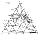
- Fig. 3 shows the phase diagram for the system Al-Cu-Ni [3] .
- the composition of the ternary alloy can also be adjusted by controlling the weld depth in the copper element, the thickness of the nickel plating and the thickness of the overlay of the aluminum sheet with the copper layer, so that brittle phases are avoided or by the dynamics of welding an adapted morphology with only very thin seams brittle phases, preferably below 5 microns, is achieved, which has a much lower susceptibility to cracking.
- the ship's image of the weld shows a golden coloration and differs significantly from the reddish copper and silver aluminum, indicating a sufficient mixing in the alloy formation.
- the welding depth depends on the welding speed, the deflection frequency, the scan width and the laser power.
- Scan width and weld depth also determine the Al content in the resulting melt.
- the depth of penetration into the lower copper element has a significant influence on the copper content in the forming melt. Cracks occur especially in areas with lower copper content.
- a laser beam power reduced to 1.5 kW is more than compensated for by the 2 mm lower scan width and the welding speed that is halved to 1.5 m / min.
- the result is a significantly greater weld depth into the copper element and a copper-rich melt composition.
- Composition in the dendrite-like zone at the transition from the copper-rich molten bath into the aluminum layer has a ratio of 1: 2 according to EDX measurements with 22 at% aluminum and 44 at% copper, which indicates the brittle intermetallic ⁇ phase (cf. , Fig.2 ).
- the oxygen content is very high at 33 at%. Assuming that a sufficient protective gas atmosphere was present during welding, the oxygen content must originate from the passive layers of the Al and Cu materials. The Ni content at this point is negligible (cf. Figure 3 ).
Claims (10)
- Liaison par la matière entre de l'aluminium et du fer comprenant un composite stratifié constitué par un élément en cuivre (2), une couche d'aluminium (1) et une couche de cuivre (3) appliquée sur celle-ci, dans l'ordre susmentionné,
caractérisé en ce que
la liaison comprend au moins un cordon de soudure (4) sur la couche de cuivre, ce cordon de soudure s'étendant dans l'élément en cuivre au travers de la couche de cuivre et de la couche d'aluminium. - Liaison par la matière conforme à la revendication 1,
caractérisé en ce que
la couche d'aluminium (1) est une tôle d'aluminium et/ou la couche de cuivre (3) est un film ou un feuilletage appliqué sur la couche d'aluminium. - Liaison par la matière conforme à la revendication 1 ou 2, comprenant une autre couche (5) en nickel appliquée sur la couche de cuivre (3) à l'opposé de la couche d'aluminium.
- Liaison par la matière conforme à l'une des revendications précédentes,
caractérisé en ce que
le cordon de soudure (4) de la couche de cuivre (3) s'étend sur une ligne de soudage. - Liaison par la matière conforme à la revendication 4,
caractérisé en ce que
la ligne de soudage suit une ligne cyclique autour d'une ligne médiane. - Procédé d'obtention d'une liaison par la matière entre de l'aluminium et du cuivre comprenant les étapes suivantes consistant à :a) préparer un élément en cuivre (2), une couche d'aluminium (1) et une couche de cuivre (3),b) appliquer la couche d'aluminium sur l'élément en cuivre et la couche de cuivre sur la couche d'aluminium pour obtenir un composite stratifié,caractérisé par
une étape consistant à souder localement l'élément en cuivre, la couche d'aluminium et la couche de cuivre sous l'action d'une source de chaleur (6) en formant un cordon de soudure (4) s'étendant dans l'élément en cuivre au travers de la couche de cuivre et de la couche d'aluminium, la source de chaleur agissant sur la couche de cuivre. - Procédé conforme à la revendication 6,
caractérisé en ce que
la source de chaleur est formée par un faisceau laser (6). - Procédé conforme à la revendication 6 ou 7,
caractérisé en ce que
le soudage local est effectué par l'action en série de la source de chaleur le long d'une ligne de soudage sur la couche de cuivre, le cordon de soudure suivant la ligne de soudage. - Procédé conforme à la revendication 6,
caractérisé en ce que
la source de chaleur oscille autour d'une ligne médiane sur la couche de cuivre avec une fréquence de déviation cyclique comprise entre 150 et 500 Hz en formant une configuration périodique de la ligne de soudage. - Procédé conforme à l'une des revendications 6 à 9,
caractérisé en ce que
la source de chaleur agit de manière pulsée sur la couche de cuivre.
Priority Applications (1)
| Application Number | Priority Date | Filing Date | Title |
|---|---|---|---|
| PL15001164T PL2995414T3 (pl) | 2014-07-30 | 2015-04-21 | Połączenie materiałowe między aluminium i miedzią oraz sposób jego wytwarzania |
Applications Claiming Priority (1)
| Application Number | Priority Date | Filing Date | Title |
|---|---|---|---|
| DE102014110777.2A DE102014110777B4 (de) | 2014-07-30 | 2014-07-30 | Stoffschlüssige Verbindung zwischen Aluminium und Kupfer sowie Verfahren zur Herstellung derselben |
Publications (2)
| Publication Number | Publication Date |
|---|---|
| EP2995414A1 EP2995414A1 (fr) | 2016-03-16 |
| EP2995414B1 true EP2995414B1 (fr) | 2017-07-05 |
Family
ID=53180488
Family Applications (1)
| Application Number | Title | Priority Date | Filing Date |
|---|---|---|---|
| EP15001164.1A Not-in-force EP2995414B1 (fr) | 2014-07-30 | 2015-04-21 | Liaison de matière entre aluminium et cuivre et son procédé de fabrication |
Country Status (5)
| Country | Link |
|---|---|
| US (1) | US20160031042A1 (fr) |
| EP (1) | EP2995414B1 (fr) |
| DE (1) | DE102014110777B4 (fr) |
| HU (1) | HUE034600T2 (fr) |
| PL (1) | PL2995414T3 (fr) |
Families Citing this family (10)
| Publication number | Priority date | Publication date | Assignee | Title |
|---|---|---|---|---|
| EP3216552B1 (fr) * | 2016-03-09 | 2018-12-12 | NGK Spark Plug Co., Ltd. | Procédés de soudage laser, procédé de fabrication d'un corps soudé, procédé de fabrication d'une électrode de bougie d'allumage et procédé de fabrication d'une bougie d'allumage utilisant de tels procédés de soudage laser |
| CN109462986B (zh) * | 2016-07-14 | 2021-01-26 | 通用汽车环球科技运作有限责任公司 | 涂层钢的多束激光点焊 |
| JP6681543B2 (ja) | 2016-07-21 | 2020-04-15 | パナソニックIpマネジメント株式会社 | 溶接金属部材とその溶接金属部材を有する電池 |
| CN111867784B (zh) | 2018-01-30 | 2022-05-27 | 米沃基电子工具公司 | 动力工具 |
| CN108838541B (zh) * | 2018-09-14 | 2020-07-24 | 苏州大学 | 一种汽车用冷轧钢板的激光焊接方法及其焊接接头 |
| CN109079324A (zh) * | 2018-09-30 | 2018-12-25 | 大族激光科技产业集团股份有限公司 | 白铜的激光焊接方法 |
| HUE057988T2 (hu) * | 2018-11-14 | 2022-06-28 | Rogers Bv | Eljárás gyûjtõsín elõállítására és az így készített gyûjtõsín |
| CN220783770U (zh) | 2020-08-07 | 2024-04-16 | 米沃奇电动工具公司 | 在工具中使用的压接头 |
| CN113634893A (zh) * | 2021-08-13 | 2021-11-12 | 远景动力技术(江苏)有限公司 | 铜采样端子与铝极耳的焊接方法、电池 |
| CN114833446B (zh) * | 2022-04-29 | 2024-04-30 | 三一技术装备有限公司 | 电池全激光焊接制造方法 |
Family Cites Families (4)
| Publication number | Priority date | Publication date | Assignee | Title |
|---|---|---|---|---|
| DE102004009651B4 (de) * | 2004-02-27 | 2008-10-09 | BLZ Bayerisches Laserzentrum Gemeinnützige Forschungsgesellschaft mbH | Verfahren zum Schweißen artungleicher metallischer Fügepartner, insbesondere von Aluminium-Kupfer-Verbindungsstellen |
| KR100842493B1 (ko) * | 2004-08-09 | 2008-07-01 | 닛본 덴끼 가부시끼가이샤 | 이금속 박판의 용접 방법, 이금속 박판 접합체, 전기디바이스 및 전기 디바이스 집합체 |
| JP2010075967A (ja) * | 2008-09-26 | 2010-04-08 | Nec Personal Products Co Ltd | 異種金属の溶接方法 |
| DE102010039893A1 (de) * | 2010-08-27 | 2012-03-01 | Robert Bosch Gmbh | Fügekörper und Verfahren zur Herstellung eines Fügekörpers |
-
2014
- 2014-07-30 DE DE102014110777.2A patent/DE102014110777B4/de not_active Expired - Fee Related
-
2015
- 2015-04-21 HU HUE15001164A patent/HUE034600T2/hu unknown
- 2015-04-21 PL PL15001164T patent/PL2995414T3/pl unknown
- 2015-04-21 EP EP15001164.1A patent/EP2995414B1/fr not_active Not-in-force
- 2015-06-12 US US14/738,641 patent/US20160031042A1/en not_active Abandoned
Also Published As
| Publication number | Publication date |
|---|---|
| PL2995414T3 (pl) | 2017-12-29 |
| HUE034600T2 (hu) | 2018-02-28 |
| DE102014110777A1 (de) | 2016-02-04 |
| EP2995414A1 (fr) | 2016-03-16 |
| US20160031042A1 (en) | 2016-02-04 |
| DE102014110777B4 (de) | 2016-08-18 |
Similar Documents
| Publication | Publication Date | Title |
|---|---|---|
| EP2995414B1 (fr) | Liaison de matière entre aluminium et cuivre et son procédé de fabrication | |
| EP1600246B1 (fr) | Rail de siege de titan et d'aluminium | |
| EP3448622B1 (fr) | Méthode de soudage par faisceau laser visible de composant électronique, d'équipement électrique d'automobile, de batterie et d'autres composants | |
| WO2005082569A1 (fr) | Procede de soudage de pieces metalliques de nature differente a joindre, en particulier de sites de liaison aluminium-cuivre | |
| JP6681543B2 (ja) | 溶接金属部材とその溶接金属部材を有する電池 | |
| DE102007020389B4 (de) | Fügeverfahren zum Fügen von Bauteilen im Luft- und Raumfahrtbereich | |
| DE102006050653A1 (de) | Verfahren und Vorrichtung zum stoffschlüssigen Verbinden eines optischen Elementes mit einer Fassung | |
| EP0805733B1 (fr) | Procede pour l'assemblage de bandes assiste par laser | |
| DE102010013351A1 (de) | Kontaktelement für Ableiter galvanischer Zellen | |
| EP1632463B1 (fr) | Materiau composite | |
| DE102009013110A1 (de) | Laserschweissstruktur und Laserschweissverfahren | |
| WO2008009670A1 (fr) | Procédé de création d'une liaison par soudage ou diffusion | |
| WO2009129801A1 (fr) | Procédé pour l'assemblage d'au moins deux éléments transparents par soudage laser par transparence | |
| DE102008002910A1 (de) | Verfahren und Vorrichtung zum Verbinden von Bauteilen mittels Laserstrahlung | |
| DE102019211070B3 (de) | Fertigungsverfahren zum Verschweißen eines Kupferleiters mit einem Werkstück, Werkstück und Fahrzeug | |
| DE102019114875A1 (de) | Verfahren und vorrichtung zum laserschweissen | |
| EP2380690B1 (fr) | Assemblage de pièces en matières métalliques et/ou céramiques à l'aide d'une matière première additionnelle vitrocéramique et d'un faisceau laser ; Joint avec deux pièces en matières métalliques et/ou céramiques | |
| DE102020120263B3 (de) | Verschweißen von metallischen Folien mittels Laser | |
| Liu et al. | Effect of laser-processing parameters on the formation and properties of a stellite hardfacing coating | |
| DE102011010457A1 (de) | Verfahren zum Herstellen einer Batterie | |
| EP2144284A1 (fr) | Procédé de fabrication d'un connecteur sur un élément semi-conducteur pour un distributeur d'énergie et composant électronique doté d'un connecteur fabriqué de cette manière sur un composant semi-conducteur | |
| DE102017104010A1 (de) | Zusammenpassende elektroden zum widerstandspunktschweissen von aluminiumwerkstücken an stahlwerkstücke | |
| EP4045224A1 (fr) | Procédé d'usinage d'une feuille de lithium ou d'une feuille métallique revêtue de lithium au moyen d'un faisceau laser | |
| WO2014134643A1 (fr) | Assemblage soudé de métaux réfractaires | |
| DE102013109588A1 (de) | Aufschmelz-Verbindungsverfahren |
Legal Events
| Date | Code | Title | Description |
|---|---|---|---|
| PUAI | Public reference made under article 153(3) epc to a published international application that has entered the european phase |
Free format text: ORIGINAL CODE: 0009012 |
|
| AK | Designated contracting states |
Kind code of ref document: A1 Designated state(s): AL AT BE BG CH CY CZ DE DK EE ES FI FR GB GR HR HU IE IS IT LI LT LU LV MC MK MT NL NO PL PT RO RS SE SI SK SM TR |
|
| AX | Request for extension of the european patent |
Extension state: BA ME |
|
| 17P | Request for examination filed |
Effective date: 20160914 |
|
| RBV | Designated contracting states (corrected) |
Designated state(s): AL AT BE BG CH CY CZ DE DK EE ES FI FR GB GR HR HU IE IS IT LI LT LU LV MC MK MT NL NO PL PT RO RS SE SI SK SM TR |
|
| RIC1 | Information provided on ipc code assigned before grant |
Ipc: B23K 26/244 20140101ALI20161215BHEP Ipc: B23K 103/12 20060101ALN20161215BHEP Ipc: B23K 103/10 20060101ALN20161215BHEP Ipc: B23K 26/323 20140101AFI20161215BHEP |
|
| GRAP | Despatch of communication of intention to grant a patent |
Free format text: ORIGINAL CODE: EPIDOSNIGR1 |
|
| INTG | Intention to grant announced |
Effective date: 20170126 |
|
| RIC1 | Information provided on ipc code assigned before grant |
Ipc: B23K 103/10 20060101ALN20170117BHEP Ipc: B23K 103/12 20060101ALN20170117BHEP Ipc: B23K 26/323 20140101AFI20170117BHEP Ipc: B23K 26/244 20140101ALI20170117BHEP |
|
| GRAS | Grant fee paid |
Free format text: ORIGINAL CODE: EPIDOSNIGR3 |
|
| GRAA | (expected) grant |
Free format text: ORIGINAL CODE: 0009210 |
|
| AK | Designated contracting states |
Kind code of ref document: B1 Designated state(s): AL AT BE BG CH CY CZ DE DK EE ES FI FR GB GR HR HU IE IS IT LI LT LU LV MC MK MT NL NO PL PT RO RS SE SI SK SM TR |
|
| REG | Reference to a national code |
Ref country code: GB Ref legal event code: FG4D Free format text: NOT ENGLISH |
|
| REG | Reference to a national code |
Ref country code: CH Ref legal event code: EP |
|
| REG | Reference to a national code |
Ref country code: AT Ref legal event code: REF Ref document number: 906263 Country of ref document: AT Kind code of ref document: T Effective date: 20170715 |
|
| REG | Reference to a national code |
Ref country code: IE Ref legal event code: FG4D Free format text: LANGUAGE OF EP DOCUMENT: GERMAN |
|
| REG | Reference to a national code |
Ref country code: DE Ref legal event code: R096 Ref document number: 502015001354 Country of ref document: DE |
|
| REG | Reference to a national code |
Ref country code: NL Ref legal event code: MP Effective date: 20170705 |
|
| REG | Reference to a national code |
Ref country code: LT Ref legal event code: MG4D |
|
| PG25 | Lapsed in a contracting state [announced via postgrant information from national office to epo] |
Ref country code: HR Free format text: LAPSE BECAUSE OF FAILURE TO SUBMIT A TRANSLATION OF THE DESCRIPTION OR TO PAY THE FEE WITHIN THE PRESCRIBED TIME-LIMIT Effective date: 20170705 Ref country code: NO Free format text: LAPSE BECAUSE OF FAILURE TO SUBMIT A TRANSLATION OF THE DESCRIPTION OR TO PAY THE FEE WITHIN THE PRESCRIBED TIME-LIMIT Effective date: 20171005 Ref country code: FI Free format text: LAPSE BECAUSE OF FAILURE TO SUBMIT A TRANSLATION OF THE DESCRIPTION OR TO PAY THE FEE WITHIN THE PRESCRIBED TIME-LIMIT Effective date: 20170705 Ref country code: NL Free format text: LAPSE BECAUSE OF FAILURE TO SUBMIT A TRANSLATION OF THE DESCRIPTION OR TO PAY THE FEE WITHIN THE PRESCRIBED TIME-LIMIT Effective date: 20170705 Ref country code: LT Free format text: LAPSE BECAUSE OF FAILURE TO SUBMIT A TRANSLATION OF THE DESCRIPTION OR TO PAY THE FEE WITHIN THE PRESCRIBED TIME-LIMIT Effective date: 20170705 Ref country code: SE Free format text: LAPSE BECAUSE OF FAILURE TO SUBMIT A TRANSLATION OF THE DESCRIPTION OR TO PAY THE FEE WITHIN THE PRESCRIBED TIME-LIMIT Effective date: 20170705 |
|
| PG25 | Lapsed in a contracting state [announced via postgrant information from national office to epo] |
Ref country code: LV Free format text: LAPSE BECAUSE OF FAILURE TO SUBMIT A TRANSLATION OF THE DESCRIPTION OR TO PAY THE FEE WITHIN THE PRESCRIBED TIME-LIMIT Effective date: 20170705 Ref country code: BG Free format text: LAPSE BECAUSE OF FAILURE TO SUBMIT A TRANSLATION OF THE DESCRIPTION OR TO PAY THE FEE WITHIN THE PRESCRIBED TIME-LIMIT Effective date: 20171005 Ref country code: GR Free format text: LAPSE BECAUSE OF FAILURE TO SUBMIT A TRANSLATION OF THE DESCRIPTION OR TO PAY THE FEE WITHIN THE PRESCRIBED TIME-LIMIT Effective date: 20171006 Ref country code: RS Free format text: LAPSE BECAUSE OF FAILURE TO SUBMIT A TRANSLATION OF THE DESCRIPTION OR TO PAY THE FEE WITHIN THE PRESCRIBED TIME-LIMIT Effective date: 20170705 Ref country code: IS Free format text: LAPSE BECAUSE OF FAILURE TO SUBMIT A TRANSLATION OF THE DESCRIPTION OR TO PAY THE FEE WITHIN THE PRESCRIBED TIME-LIMIT Effective date: 20171105 Ref country code: ES Free format text: LAPSE BECAUSE OF FAILURE TO SUBMIT A TRANSLATION OF THE DESCRIPTION OR TO PAY THE FEE WITHIN THE PRESCRIBED TIME-LIMIT Effective date: 20170705 |
|
| REG | Reference to a national code |
Ref country code: HU Ref legal event code: AG4A Ref document number: E034600 Country of ref document: HU |
|
| REG | Reference to a national code |
Ref country code: DE Ref legal event code: R097 Ref document number: 502015001354 Country of ref document: DE |
|
| REG | Reference to a national code |
Ref country code: FR Ref legal event code: PLFP Year of fee payment: 4 |
|
| PG25 | Lapsed in a contracting state [announced via postgrant information from national office to epo] |
Ref country code: DK Free format text: LAPSE BECAUSE OF FAILURE TO SUBMIT A TRANSLATION OF THE DESCRIPTION OR TO PAY THE FEE WITHIN THE PRESCRIBED TIME-LIMIT Effective date: 20170705 Ref country code: RO Free format text: LAPSE BECAUSE OF FAILURE TO SUBMIT A TRANSLATION OF THE DESCRIPTION OR TO PAY THE FEE WITHIN THE PRESCRIBED TIME-LIMIT Effective date: 20170705 |
|
| PLBE | No opposition filed within time limit |
Free format text: ORIGINAL CODE: 0009261 |
|
| STAA | Information on the status of an ep patent application or granted ep patent |
Free format text: STATUS: NO OPPOSITION FILED WITHIN TIME LIMIT |
|
| PG25 | Lapsed in a contracting state [announced via postgrant information from national office to epo] |
Ref country code: SK Free format text: LAPSE BECAUSE OF FAILURE TO SUBMIT A TRANSLATION OF THE DESCRIPTION OR TO PAY THE FEE WITHIN THE PRESCRIBED TIME-LIMIT Effective date: 20170705 Ref country code: SM Free format text: LAPSE BECAUSE OF FAILURE TO SUBMIT A TRANSLATION OF THE DESCRIPTION OR TO PAY THE FEE WITHIN THE PRESCRIBED TIME-LIMIT Effective date: 20170705 Ref country code: IT Free format text: LAPSE BECAUSE OF FAILURE TO SUBMIT A TRANSLATION OF THE DESCRIPTION OR TO PAY THE FEE WITHIN THE PRESCRIBED TIME-LIMIT Effective date: 20170705 Ref country code: EE Free format text: LAPSE BECAUSE OF FAILURE TO SUBMIT A TRANSLATION OF THE DESCRIPTION OR TO PAY THE FEE WITHIN THE PRESCRIBED TIME-LIMIT Effective date: 20170705 |
|
| 26N | No opposition filed |
Effective date: 20180406 |
|
| PG25 | Lapsed in a contracting state [announced via postgrant information from national office to epo] |
Ref country code: SI Free format text: LAPSE BECAUSE OF FAILURE TO SUBMIT A TRANSLATION OF THE DESCRIPTION OR TO PAY THE FEE WITHIN THE PRESCRIBED TIME-LIMIT Effective date: 20170705 |
|
| PG25 | Lapsed in a contracting state [announced via postgrant information from national office to epo] |
Ref country code: MT Free format text: LAPSE BECAUSE OF FAILURE TO SUBMIT A TRANSLATION OF THE DESCRIPTION OR TO PAY THE FEE WITHIN THE PRESCRIBED TIME-LIMIT Effective date: 20170705 |
|
| PG25 | Lapsed in a contracting state [announced via postgrant information from national office to epo] |
Ref country code: MC Free format text: LAPSE BECAUSE OF FAILURE TO SUBMIT A TRANSLATION OF THE DESCRIPTION OR TO PAY THE FEE WITHIN THE PRESCRIBED TIME-LIMIT Effective date: 20170705 |
|
| REG | Reference to a national code |
Ref country code: CH Ref legal event code: PL |
|
| REG | Reference to a national code |
Ref country code: BE Ref legal event code: MM Effective date: 20180430 |
|
| REG | Reference to a national code |
Ref country code: IE Ref legal event code: MM4A |
|
| PG25 | Lapsed in a contracting state [announced via postgrant information from national office to epo] |
Ref country code: LU Free format text: LAPSE BECAUSE OF NON-PAYMENT OF DUE FEES Effective date: 20180421 |
|
| PG25 | Lapsed in a contracting state [announced via postgrant information from national office to epo] |
Ref country code: BE Free format text: LAPSE BECAUSE OF NON-PAYMENT OF DUE FEES Effective date: 20180430 Ref country code: CH Free format text: LAPSE BECAUSE OF NON-PAYMENT OF DUE FEES Effective date: 20180430 Ref country code: LI Free format text: LAPSE BECAUSE OF NON-PAYMENT OF DUE FEES Effective date: 20180430 |
|
| PG25 | Lapsed in a contracting state [announced via postgrant information from national office to epo] |
Ref country code: IE Free format text: LAPSE BECAUSE OF NON-PAYMENT OF DUE FEES Effective date: 20180421 |
|
| PGFP | Annual fee paid to national office [announced via postgrant information from national office to epo] |
Ref country code: DE Payment date: 20190418 Year of fee payment: 6 Ref country code: CZ Payment date: 20190411 Year of fee payment: 5 |
|
| PGFP | Annual fee paid to national office [announced via postgrant information from national office to epo] |
Ref country code: HU Payment date: 20190411 Year of fee payment: 5 Ref country code: FR Payment date: 20190423 Year of fee payment: 5 |
|
| PGFP | Annual fee paid to national office [announced via postgrant information from national office to epo] |
Ref country code: GB Payment date: 20190424 Year of fee payment: 5 |
|
| PG25 | Lapsed in a contracting state [announced via postgrant information from national office to epo] |
Ref country code: TR Free format text: LAPSE BECAUSE OF FAILURE TO SUBMIT A TRANSLATION OF THE DESCRIPTION OR TO PAY THE FEE WITHIN THE PRESCRIBED TIME-LIMIT Effective date: 20170705 |
|
| PG25 | Lapsed in a contracting state [announced via postgrant information from national office to epo] |
Ref country code: PT Free format text: LAPSE BECAUSE OF FAILURE TO SUBMIT A TRANSLATION OF THE DESCRIPTION OR TO PAY THE FEE WITHIN THE PRESCRIBED TIME-LIMIT Effective date: 20170705 |
|
| PG25 | Lapsed in a contracting state [announced via postgrant information from national office to epo] |
Ref country code: MK Free format text: LAPSE BECAUSE OF NON-PAYMENT OF DUE FEES Effective date: 20170705 Ref country code: CY Free format text: LAPSE BECAUSE OF FAILURE TO SUBMIT A TRANSLATION OF THE DESCRIPTION OR TO PAY THE FEE WITHIN THE PRESCRIBED TIME-LIMIT Effective date: 20170705 |
|
| PG25 | Lapsed in a contracting state [announced via postgrant information from national office to epo] |
Ref country code: AL Free format text: LAPSE BECAUSE OF FAILURE TO SUBMIT A TRANSLATION OF THE DESCRIPTION OR TO PAY THE FEE WITHIN THE PRESCRIBED TIME-LIMIT Effective date: 20170705 |
|
| PGFP | Annual fee paid to national office [announced via postgrant information from national office to epo] |
Ref country code: DE Payment date: 20200423 Year of fee payment: 6 |
|
| PG25 | Lapsed in a contracting state [announced via postgrant information from national office to epo] |
Ref country code: CZ Free format text: LAPSE BECAUSE OF NON-PAYMENT OF DUE FEES Effective date: 20200421 Ref country code: FR Free format text: LAPSE BECAUSE OF NON-PAYMENT OF DUE FEES Effective date: 20200430 Ref country code: HU Free format text: LAPSE BECAUSE OF NON-PAYMENT OF DUE FEES Effective date: 20200422 |
|
| GBPC | Gb: european patent ceased through non-payment of renewal fee |
Effective date: 20200421 |
|
| PG25 | Lapsed in a contracting state [announced via postgrant information from national office to epo] |
Ref country code: GB Free format text: LAPSE BECAUSE OF NON-PAYMENT OF DUE FEES Effective date: 20200421 |
|
| REG | Reference to a national code |
Ref country code: AT Ref legal event code: MM01 Ref document number: 906263 Country of ref document: AT Kind code of ref document: T Effective date: 20200421 |
|
| PG25 | Lapsed in a contracting state [announced via postgrant information from national office to epo] |
Ref country code: AT Free format text: LAPSE BECAUSE OF NON-PAYMENT OF DUE FEES Effective date: 20200421 |
|
| REG | Reference to a national code |
Ref country code: DE Ref legal event code: R119 Ref document number: 502015001354 Country of ref document: DE |
|
| PG25 | Lapsed in a contracting state [announced via postgrant information from national office to epo] |
Ref country code: DE Free format text: LAPSE BECAUSE OF NON-PAYMENT OF DUE FEES Effective date: 20211103 |
|
| PG25 | Lapsed in a contracting state [announced via postgrant information from national office to epo] |
Ref country code: PL Free format text: LAPSE BECAUSE OF NON-PAYMENT OF DUE FEES Effective date: 20200421 |