EP2995362A1 - Filterelement mit niedriger Akkumulation von elektrostatischen Ladungen - Google Patents
Filterelement mit niedriger Akkumulation von elektrostatischen Ladungen Download PDFInfo
- Publication number
- EP2995362A1 EP2995362A1 EP14425112.1A EP14425112A EP2995362A1 EP 2995362 A1 EP2995362 A1 EP 2995362A1 EP 14425112 A EP14425112 A EP 14425112A EP 2995362 A1 EP2995362 A1 EP 2995362A1
- Authority
- EP
- European Patent Office
- Prior art keywords
- filtration
- septum
- filtration element
- conductive
- net
- Prior art date
- Legal status (The legal status is an assumption and is not a legal conclusion. Google has not performed a legal analysis and makes no representation as to the accuracy of the status listed.)
- Withdrawn
Links
- 238000009825 accumulation Methods 0.000 title description 4
- 238000001914 filtration Methods 0.000 claims abstract description 59
- 239000000463 material Substances 0.000 claims abstract description 15
- 229920001940 conductive polymer Polymers 0.000 claims abstract description 4
- 239000012530 fluid Substances 0.000 claims description 18
- 239000004033 plastic Substances 0.000 claims description 7
- 238000003466 welding Methods 0.000 claims description 7
- 239000004744 fabric Substances 0.000 claims description 6
- 238000002604 ultrasonography Methods 0.000 claims description 6
- 239000004020 conductor Substances 0.000 claims description 5
- 239000003292 glue Substances 0.000 claims description 2
- 238000007789 sealing Methods 0.000 claims description 2
- 238000005516 engineering process Methods 0.000 abstract description 3
- 238000011144 upstream manufacturing Methods 0.000 abstract description 3
- 238000000034 method Methods 0.000 abstract description 2
- 239000000835 fiber Substances 0.000 description 4
- 229920005989 resin Polymers 0.000 description 4
- 239000011347 resin Substances 0.000 description 4
- OKTJSMMVPCPJKN-UHFFFAOYSA-N Carbon Chemical compound [C] OKTJSMMVPCPJKN-UHFFFAOYSA-N 0.000 description 3
- 229920001410 Microfiber Polymers 0.000 description 3
- 239000000853 adhesive Substances 0.000 description 3
- 230000001070 adhesive effect Effects 0.000 description 3
- 230000015572 biosynthetic process Effects 0.000 description 3
- 229910052799 carbon Inorganic materials 0.000 description 3
- 230000000694 effects Effects 0.000 description 3
- 239000007769 metal material Substances 0.000 description 3
- 239000003658 microfiber Substances 0.000 description 3
- 239000000654 additive Substances 0.000 description 2
- 229920000642 polymer Polymers 0.000 description 2
- 239000011148 porous material Substances 0.000 description 2
- 238000003825 pressing Methods 0.000 description 2
- 239000004593 Epoxy Substances 0.000 description 1
- NINIDFKCEFEMDL-UHFFFAOYSA-N Sulfur Chemical compound [S] NINIDFKCEFEMDL-UHFFFAOYSA-N 0.000 description 1
- 239000005864 Sulphur Substances 0.000 description 1
- HCHKCACWOHOZIP-UHFFFAOYSA-N Zinc Chemical compound [Zn] HCHKCACWOHOZIP-UHFFFAOYSA-N 0.000 description 1
- 238000011101 absolute filtration Methods 0.000 description 1
- NIXOWILDQLNWCW-UHFFFAOYSA-N acrylic acid group Chemical group C(C=C)(=O)O NIXOWILDQLNWCW-UHFFFAOYSA-N 0.000 description 1
- 238000004026 adhesive bonding Methods 0.000 description 1
- 238000000576 coating method Methods 0.000 description 1
- 238000010276 construction Methods 0.000 description 1
- 238000011109 contamination Methods 0.000 description 1
- 239000003344 environmental pollutant Substances 0.000 description 1
- 239000003822 epoxy resin Substances 0.000 description 1
- 238000001125 extrusion Methods 0.000 description 1
- 239000011521 glass Substances 0.000 description 1
- 238000002844 melting Methods 0.000 description 1
- 239000002071 nanotube Substances 0.000 description 1
- 239000002245 particle Substances 0.000 description 1
- 231100000719 pollutant Toxicity 0.000 description 1
- 229920000647 polyepoxide Polymers 0.000 description 1
- 229920000728 polyester Polymers 0.000 description 1
- 238000006116 polymerization reaction Methods 0.000 description 1
- 239000007787 solid Substances 0.000 description 1
- 239000000126 substance Substances 0.000 description 1
- 239000012815 thermoplastic material Substances 0.000 description 1
- 238000009941 weaving Methods 0.000 description 1
- 229910052725 zinc Inorganic materials 0.000 description 1
- 239000011701 zinc Substances 0.000 description 1
Images


Classifications
-
- B—PERFORMING OPERATIONS; TRANSPORTING
- B01—PHYSICAL OR CHEMICAL PROCESSES OR APPARATUS IN GENERAL
- B01D—SEPARATION
- B01D46/00—Filters or filtering processes specially modified for separating dispersed particles from gases or vapours
- B01D46/24—Particle separators, e.g. dust precipitators, using rigid hollow filter bodies
- B01D46/2403—Particle separators, e.g. dust precipitators, using rigid hollow filter bodies characterised by the physical shape or structure of the filtering element
- B01D46/2411—Filter cartridges
- B01D46/2414—End caps including additional functions or special forms
-
- B—PERFORMING OPERATIONS; TRANSPORTING
- B01—PHYSICAL OR CHEMICAL PROCESSES OR APPARATUS IN GENERAL
- B01D—SEPARATION
- B01D29/00—Filters with filtering elements stationary during filtration, e.g. pressure or suction filters, not covered by groups B01D24/00 - B01D27/00; Filtering elements therefor
- B01D29/11—Filters with filtering elements stationary during filtration, e.g. pressure or suction filters, not covered by groups B01D24/00 - B01D27/00; Filtering elements therefor with bag, cage, hose, tube, sleeve or like filtering elements
- B01D29/111—Making filtering elements
-
- B—PERFORMING OPERATIONS; TRANSPORTING
- B01—PHYSICAL OR CHEMICAL PROCESSES OR APPARATUS IN GENERAL
- B01D—SEPARATION
- B01D29/00—Filters with filtering elements stationary during filtration, e.g. pressure or suction filters, not covered by groups B01D24/00 - B01D27/00; Filtering elements therefor
- B01D29/11—Filters with filtering elements stationary during filtration, e.g. pressure or suction filters, not covered by groups B01D24/00 - B01D27/00; Filtering elements therefor with bag, cage, hose, tube, sleeve or like filtering elements
- B01D29/13—Supported filter elements
- B01D29/15—Supported filter elements arranged for inward flow filtration
- B01D29/21—Supported filter elements arranged for inward flow filtration with corrugated, folded or wound sheets
-
- B—PERFORMING OPERATIONS; TRANSPORTING
- B01—PHYSICAL OR CHEMICAL PROCESSES OR APPARATUS IN GENERAL
- B01D—SEPARATION
- B01D46/00—Filters or filtering processes specially modified for separating dispersed particles from gases or vapours
- B01D46/42—Auxiliary equipment or operation thereof
- B01D46/50—Means for discharging electrostatic potential
-
- B—PERFORMING OPERATIONS; TRANSPORTING
- B01—PHYSICAL OR CHEMICAL PROCESSES OR APPARATUS IN GENERAL
- B01D—SEPARATION
- B01D2201/00—Details relating to filtering apparatus
- B01D2201/04—Supports for the filtering elements
- B01D2201/0407—Perforated supports on both sides of the filtering element
-
- B—PERFORMING OPERATIONS; TRANSPORTING
- B01—PHYSICAL OR CHEMICAL PROCESSES OR APPARATUS IN GENERAL
- B01D—SEPARATION
- B01D2201/00—Details relating to filtering apparatus
- B01D2201/12—Pleated filters
-
- B—PERFORMING OPERATIONS; TRANSPORTING
- B01—PHYSICAL OR CHEMICAL PROCESSES OR APPARATUS IN GENERAL
- B01D—SEPARATION
- B01D2201/00—Details relating to filtering apparatus
- B01D2201/50—Means for dissipating electrostatic charges
Definitions
- the present invention relates to a filtration element which controls fluid contamination thus remarkably reducing the formation of electrostatic charges generated in the circuit owing to the triboelectric effect.
- the triboelectric effect is known in the technical field and consists in the electric charges transfer, and therefore in the generation of a voltage, between different materials (at least one thereof being isolating), which occurs when these materials are crossed by a fluid which generates friction while passing therethrough.
- Object of the present invention is a filtration element which is also able to eliminate, itself, possible electrostatic discharges between the various layers of the filtration septum and the components of the circuit.
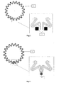
- a first embodiment of the inventive object shows the filtration element as a whole, it comprising a multi-holed inner support tube 4, a multi-holed outer protection 3, two opposed terminals 1, 2 and a filtration septum 11 positioned between the inner tube 4 and the outer protection 3.
- filtration septum 11 Going from outside to inside said filtration septum 11 is made up of a nonconductive outer net 5 (having surface resistivity > 10 12 ⁇ ), a conductive spunbonded fabric 6 (or spunbond, having surface resistivity between 10 1 ⁇ and 10 3 ⁇ ), a main nonconductive filtration layer 7, a conductive spunbonded fabric 8 (or spunbond) and a conductive or in plastic material inner support net 9.
- the multilayer material is cut by the bobbin with a longitudinal cut and is folded to provide a filtration septum 11 as sown in figs. 2 and 3 .
- the filtration septum 11 has a special closure 10 realized by ultrasound welding by means of knurled sonotrodes and is fixed to terminals 1, 2 by means of a resinous glue 12 and a particular assembling method.
- the ultrasound welding is provided by applying a variable normal charge to the pieces to be welded and by putting in vibration a portion with respect to the other ones by means of the vibrating group formed by a piezoelectric transducer and a booster to the end of which a sonotrode is screwed.
- the sonotrode generates friction between the portions by means of a vibration with ultrasonic frequency. This intense vibration generates heat and as a consequence the thermoplastic materials melt, so that welding and assembly are ensured.
- a first innovative aspect of the filtration element 100 object of the present invention relates to the filtration septum 11 realized with nonconductive main fibre and conductive spunbond arranged close with respect to each other according to dedicated technologies, as for example pre-heated pleating and thermo-melting of filtration materials.
- the closure 10 of the last two folds of the filtration septum 11, as shown in figs. 2 and 3 is carried out with ultrasound welding which ensures a perfect seal at the passage of the fluid and a perfect electric continuity of the fibers, thus ensuring a constant value of resistivity between the various conductive materials (spunbond) between the upstream area and the downstream area of the filter.
- Said ultrasound welding is carried out by controlling specific parameters such for example frequencies, pressures and times.
- the seal of the filtration septum 11 is integrated with a seal by means of bi-component epoxy resin.
- the seal is ended the electric continuity between the spunbond layers 6, 8 of the fibre 7 is verified by a means apt to detect its conductivity.
- the filtration septum 11 can also be protected from the entrance side of the fluid by an outer cage in nonconductive plastic material and can be supported from the exit side of the fluid by a tube with suitable holes in conductive plastic or metal material (having surface resistivity between 10 3 ⁇ and 10 6 ⁇ ).
- terminals 1, 2 of the filtration element 100 which are made up of conductive plastic material (having surface resistivity between 10 3 ⁇ and 10 6 ⁇ ) additioned with nanotubes in carbon or carbon fibres.
- the terminals 1, 2 are realized in conductive polymer which ensures the electric continuity of the filtration element 100.
- the bottom has a substantially “U” shaped section and the filtration septum 11 is introduced between the wings of said "U” and stops itself against the bottom of the "U”.
- the contact section of the filtration septum 11 with the bottom is therefore of remarkable extension with respect to the known applications, for example contact pin, and this guarantees great conductivity between the components, being in contact with the whole circular crown.
- a double control pressing system (test of the axial charge and test of the filtration element conductivity) guarantees the function of the filtration element.
- the assembly steps are carried out by a suitable machine which firstly delivers a quantity of bonding resin in the terminal 1 where the yet pre-assembled filtration septum will be introduced.
- a system of calibrated weights (at least ten times the weight of the pre-assembled septum) will allow the perfect contact between the filtration septum 11 and the terminal 1 so that the floatation phenomenon in the bonding resin is avoided.
- the bonding resin is delivered in the terminal 2 and also here the pre-assembled septum is then introduced.
- the filtration element is introduced in a suitable pressing machine (which generates a force at least ten times the weight of the pre-assembled septum and maintained for a pre-fixed interval time greater than the polymerization time of the used bonding resin).
- the equipment carries out the in-line control of the electric conductivity between the two terminals 1, 2.
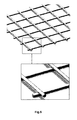
- FIG. 5 Another embodiment of the present invention, as shown in fig. 5 , provides that the outer net 5 and the inner net 9 are of nonconductive plastic material, having a mesh between 100 ⁇ m and 2000 ⁇ m.
- the passage holes of the fluid are preferably of rhomboidal, square or rectangular shape.
- the weft and warp of the net are on two different planes, to ensure an optimal passage of the fluid.
- support nets 5 and 9 made up of conductive plastic materials, which have draining function; these nets can be realized of polymers resistant to hydraulic fluids by means of extrusion or weaving technologies.
- Another embodiment provides the usage of an outer net 5 and of an inner support net 9 in not protected metal material or metal material with conductive superficial coatings, which guarantee an electric conductivity between the various elements making up the filtration element.
- This structural solution is recommended in case of very difficult usage applications, with differential high pressures at stake due to high viscosity of the fluid and significant flow rates.
- a conductive main layer 7 made up of a spunbonded fabric, which can be realized with various single or coupled materials formed by glass microfibres or nanofibres/microfibres of polymers (as for example polyester PBT, PP) which can be linked by adhesives of acrylic or epoxy kind or thermo-welded with the addition of microfibres or nanofibres of carbon or conductive polymers, which increase the electric conductivity.
- polymers as for example polyester PBT, PP
- the main filtration layer has different absolute filtration degrees between 1 ⁇ m and 50 ⁇ m (absolute efficacy 99,99%) made up of different layers with progressively smaller dimension of the fibres, which ensure uniformity of the pores from a maximum dimension up to the required pore. In addition to guarantee a constant stability during the filter life cycle, these layers ensure a high capacity of accumulation of the solid pollutant particles present in the fluid.
- Another embodiment provides the usage of a resinous adhesive 12 in conductive material for gluing the terminals to the filtration septum, and in addition to the traditional charges which increase the mechanic features and of fluid and temperature resistance, are additioned with charges of conductive materials which guarantee the electric conductivity.
- Another embodiment provides the closure 10 of the filtration septum 11 with a resinous adhesive in conductive or dissipative material, and in addition to the traditional charges which increase the mechanic features and of fluid and temperature resistance, are additioned with charges of conductive materials which guarantee the electric conductivity.
Landscapes
- Chemical & Material Sciences (AREA)
- Chemical Kinetics & Catalysis (AREA)
- Physics & Mathematics (AREA)
- Geometry (AREA)
- Filtering Materials (AREA)
Priority Applications (1)
| Application Number | Priority Date | Filing Date | Title |
|---|---|---|---|
| EP14425112.1A EP2995362A1 (de) | 2014-09-11 | 2014-09-11 | Filterelement mit niedriger Akkumulation von elektrostatischen Ladungen |
Applications Claiming Priority (1)
| Application Number | Priority Date | Filing Date | Title |
|---|---|---|---|
| EP14425112.1A EP2995362A1 (de) | 2014-09-11 | 2014-09-11 | Filterelement mit niedriger Akkumulation von elektrostatischen Ladungen |
Publications (1)
| Publication Number | Publication Date |
|---|---|
| EP2995362A1 true EP2995362A1 (de) | 2016-03-16 |
Family
ID=51868172
Family Applications (1)
| Application Number | Title | Priority Date | Filing Date |
|---|---|---|---|
| EP14425112.1A Withdrawn EP2995362A1 (de) | 2014-09-11 | 2014-09-11 | Filterelement mit niedriger Akkumulation von elektrostatischen Ladungen |
Country Status (1)
| Country | Link |
|---|---|
| EP (1) | EP2995362A1 (de) |
Cited By (2)
| Publication number | Priority date | Publication date | Assignee | Title |
|---|---|---|---|---|
| CN109663398A (zh) * | 2017-10-16 | 2019-04-23 | 曼·胡默尔有限公司 | 滤芯以及流体滤清器 |
| CN111085021A (zh) * | 2018-10-24 | 2020-05-01 | 帕尔公司 | 支撑和引流材料、过滤器、以及使用方法 |
Citations (6)
| Publication number | Priority date | Publication date | Assignee | Title |
|---|---|---|---|---|
| WO1997003744A1 (en) * | 1995-07-18 | 1997-02-06 | Parker-Hannifin Corporation | Conductive filter element |
| WO2001037969A1 (en) * | 1999-11-23 | 2001-05-31 | Pall Corporation | Conductive filter cartridge |
| WO2003033100A1 (de) * | 2001-10-16 | 2003-04-24 | Argo-Hytos Gmbh | Filterelement mit einem elektrisch leitffähigen stützgewebe |
| WO2005075055A1 (de) * | 2004-02-03 | 2005-08-18 | Hydac Filtertechnik Gmbh | Filterelement |
| WO2009089891A2 (de) * | 2008-01-15 | 2009-07-23 | Hydac Filtertechnik Gmbh | Filter |
| WO2011088869A1 (de) * | 2010-01-23 | 2011-07-28 | Hydac Filtertechnik Gmbh | Leitfähiges filterelement sowie filtervorrichtung mit filterelement |
-
2014
- 2014-09-11 EP EP14425112.1A patent/EP2995362A1/de not_active Withdrawn
Patent Citations (6)
| Publication number | Priority date | Publication date | Assignee | Title |
|---|---|---|---|---|
| WO1997003744A1 (en) * | 1995-07-18 | 1997-02-06 | Parker-Hannifin Corporation | Conductive filter element |
| WO2001037969A1 (en) * | 1999-11-23 | 2001-05-31 | Pall Corporation | Conductive filter cartridge |
| WO2003033100A1 (de) * | 2001-10-16 | 2003-04-24 | Argo-Hytos Gmbh | Filterelement mit einem elektrisch leitffähigen stützgewebe |
| WO2005075055A1 (de) * | 2004-02-03 | 2005-08-18 | Hydac Filtertechnik Gmbh | Filterelement |
| WO2009089891A2 (de) * | 2008-01-15 | 2009-07-23 | Hydac Filtertechnik Gmbh | Filter |
| WO2011088869A1 (de) * | 2010-01-23 | 2011-07-28 | Hydac Filtertechnik Gmbh | Leitfähiges filterelement sowie filtervorrichtung mit filterelement |
Cited By (3)
| Publication number | Priority date | Publication date | Assignee | Title |
|---|---|---|---|---|
| CN109663398A (zh) * | 2017-10-16 | 2019-04-23 | 曼·胡默尔有限公司 | 滤芯以及流体滤清器 |
| CN109663398B (zh) * | 2017-10-16 | 2022-08-12 | 曼·胡默尔有限公司 | 滤芯以及流体滤清器 |
| CN111085021A (zh) * | 2018-10-24 | 2020-05-01 | 帕尔公司 | 支撑和引流材料、过滤器、以及使用方法 |
Similar Documents
| Publication | Publication Date | Title |
|---|---|---|
| EP2995362A1 (de) | Filterelement mit niedriger Akkumulation von elektrostatischen Ladungen | |
| CN108712926B (zh) | 过滤器元件 | |
| EP0470485A2 (de) | Filter | |
| JP4970957B2 (ja) | フィルタ要素 | |
| KR20120004500A (ko) | 장착 플랜지 연장부를 구비한 가스 터빈용 필터 조립체 | |
| EP2585192A2 (de) | Filtermaterial für fluide und verfahren zur herstellung eines filtermaterials | |
| WO2010144132A1 (en) | Flutable fiber webs with low surface electrical resistivity for filtration | |
| CN109100395B (zh) | 一种自监测自修复碳纤维增强复合材料智能结构 | |
| JP6674025B2 (ja) | フィルタープリーツ状媒体のための支持部材 | |
| US7985275B2 (en) | Filter media and devices for high temperature filtration and methods | |
| JP2019102913A (ja) | トランスデューサ | |
| KR20160043951A (ko) | 필터 여과재 | |
| WO2014199889A1 (ja) | マイクロ流体デバイス及び誘電泳動装置 | |
| KR102142079B1 (ko) | 필터 재료 및 이로부터 제조된 필터 엘리먼트 | |
| DE10218936B4 (de) | Verfahren zur Herstellung elektromechanischer Wandler | |
| CN104056491B (zh) | 过滤器滤材和过滤器滤材的制造方法 | |
| US12090430B2 (en) | Method of producing a multilayer filter medium and a filter medium produced in accordance with this method | |
| EP4003702B1 (de) | Verfahren zum verbinden zweier bauteile aus einem thermoplastischen kunststoffmaterial | |
| KR102342836B1 (ko) | 고상 추출용 마이크로 디바이스 | |
| JP7443429B2 (ja) | 導電性ラップ付きフィルタ | |
| CN203764001U (zh) | 过滤器滤材的制造装置 | |
| JP6560101B2 (ja) | プリーツフィルター | |
| US20200023298A1 (en) | Frameless emc air filter | |
| EP2229992A1 (de) | Filter und Herstellungsverfahren dafür | |
| CA2781002C (en) | System and method for repairing a screen for use in the paper mill industry |
Legal Events
| Date | Code | Title | Description |
|---|---|---|---|
| PUAI | Public reference made under article 153(3) epc to a published international application that has entered the european phase |
Free format text: ORIGINAL CODE: 0009012 |
|
| AK | Designated contracting states |
Kind code of ref document: A1 Designated state(s): AL AT BE BG CH CY CZ DE DK EE ES FI FR GB GR HR HU IE IS IT LI LT LU LV MC MK MT NL NO PL PT RO RS SE SI SK SM TR |
|
| AX | Request for extension of the european patent |
Extension state: BA ME |
|
| 17P | Request for examination filed |
Effective date: 20160906 |
|
| RBV | Designated contracting states (corrected) |
Designated state(s): AL AT BE BG CH CY CZ DE DK EE ES FI FR GB GR HR HU IE IS IT LI LT LU LV MC MK MT NL NO PL PT RO RS SE SI SK SM TR |
|
| R17P | Request for examination filed (corrected) |
Effective date: 20160906 |
|
| RBV | Designated contracting states (corrected) |
Designated state(s): AL AT BE BG CH CY CZ DE DK EE ES FI FR GB GR HR HU IE IS IT LI LT LU LV MC MK MT NL NO PL PT RO RS SE SI SK SM TR |
|
| 17Q | First examination report despatched |
Effective date: 20180724 |
|
| STAA | Information on the status of an ep patent application or granted ep patent |
Free format text: STATUS: THE APPLICATION IS DEEMED TO BE WITHDRAWN |
|
| 18D | Application deemed to be withdrawn |
Effective date: 20181204 |