EP2995196B1 - Verbesserter applikator für informationsetiketten - Google Patents
Verbesserter applikator für informationsetiketten Download PDFInfo
- Publication number
- EP2995196B1 EP2995196B1 EP15190590.8A EP15190590A EP2995196B1 EP 2995196 B1 EP2995196 B1 EP 2995196B1 EP 15190590 A EP15190590 A EP 15190590A EP 2995196 B1 EP2995196 B1 EP 2995196B1
- Authority
- EP
- European Patent Office
- Prior art keywords
- applicator
- guide
- tag
- link
- cam
- Prior art date
- Legal status (The legal status is an assumption and is not a legal conclusion. Google has not performed a legal analysis and makes no representation as to the accuracy of the status listed.)
- Active
Links
Images




Classifications
-
- A—HUMAN NECESSITIES
- A01—AGRICULTURE; FORESTRY; ANIMAL HUSBANDRY; HUNTING; TRAPPING; FISHING
- A01K—ANIMAL HUSBANDRY; AVICULTURE; APICULTURE; PISCICULTURE; FISHING; REARING OR BREEDING ANIMALS, NOT OTHERWISE PROVIDED FOR; NEW BREEDS OF ANIMALS
- A01K11/00—Marking of animals
- A01K11/001—Ear-tags
- A01K11/002—Pliers specially adapted for fixing ear-tags to ears
Definitions
- the present invention is directed to the field of identification tags, and provides an improved applicator for applying such tags to articles, objects and animals.
- Existing identification tags are typically formed from moulded plastics. These tags usually have first and second body portions which can be folded relative to one another to close the tag. One body portion will have a piercing pin, and when the tag is folded the pin will pass through an appendage of the animal (e.g. an ear) and into a corresponding aperture on the second body portion of the tag. The pin locks in the aperture and the tag is thus secured to the animal.
- first and second body portions which can be folded relative to one another to close the tag.
- One body portion will have a piercing pin, and when the tag is folded the pin will pass through an appendage of the animal (e.g. an ear) and into a corresponding aperture on the second body portion of the tag. The pin locks in the aperture and the tag is thus secured to the animal.
- tags are usually flat when they are loaded into the jaws of the applicator, whether the loading is by hand directly into the jaws or via a semi-automatic tag delivery mechanism. In either case the applicator operator has to use a significant amount of the available hand movement just to squeeze a lever or trigger enough that the applicator folds the tag to a point where it is ready for application. This leaves little hand movement available to generate the force required to push the pin of the tag through the appendage of an animal and/or its locking aperture.
- One solution previously presented in order to reduce the amount of hand movement required for the initial folding motion was to form the tags already partially closed, with an angle of say 135 degrees between the first and second body portions of the tag. However, this solution had several drawbacks.
- the forming of the tags could be inconsistent with sets of tags having different shapes when removed from the mould, such that individual tags or groups of tags may have varying angles between the body portions. At best this can require the operator to fold the sets of tags by hand into the required shape to fit into the delivery mechanism of semi-automatic applicators, and at worst can cause tags to jam in the delivery mechanisms.
- the second drawback with these pre-formed tags was that they still required a portion of the hand movement available to the operator to be used folding the tag to an appropriate point for application, rather than allowing the operator to use all available movement to force the tag closed around or through an object or appendage.
- Semi-automatic applicators use tag delivery mechanisms in order to deliver successive tags into the applicator jaws, preferably immediately after the preceding tag has been applied.
- These delivery mechanisms can be problematic in that the members used to push the tags towards the applicator jaws can sometimes engage the wrong part of a tag, resulting in mis-feeding of the tags into the jaws and/or jamming of the delivery mechanism.
- a further problem can result in that some delivery mechanisms prevent the tags yet to be applied from being pulled back from the jaws and out of the mechanism. Thus, leftover tags have to be pulled through the mechanism, which risks injury to the operator given that most of these applicators rely on a sharp cutting blade adjacent the jaws in order to detach the applied tag from those remaining in the mechanism.
- all tags in the mechanism have to be applied, or at least folded and closed, before a new set of tags can be introduced into the mechanism.
- a further drawback of certain types of applicator is that the mechanism for retracting or releasing the applicator jaw(s) is part of the mechanism which applies the tag. This can limit the power available to close and apply a tag if the application mechanism has to both apply the tag and then release the jaws thereafter.
- FR2106705A , FR1264837A and EP055127A show examples of prior art applicators for applying individual identification tags to animals.
- EP1452089A shows an example of a prior art applicator from the present applicant which may deliver and apply multiple tags to animals.
- an identification tag applicator comprising:
- Figures 1(a) and 1(b) show projected views of either side of an identification tag applicator in accordance with the present invention.
- Figures 1(c) and 1(d) show side and front views, respectively, of the applicator.
- the applicator generally designated 10, comprises an elongate body 12 having a first end 14 and a second end 16. Fixed to the first end 14 of the body 12 is a first applicator jaw 18.
- a second applicator jaw 20 is pivotably attached to the first end 14 of the body 12 by a pivot pin 22, so that the second jaw 20 may pivot about the pivot pin 22 relative to the body 12 and close on top of the first jaw 18.
- the first and second jaws 18,20 have first and second application surfaces 19,21, respectively.
- the application surfaces 19,21 are the inner surfaces of the jaws 18,20 which will compress and fold a tag when it is being applied to an object or animal.
- a biasing member (not shown) is located between the second jaw 20 and body 12 in order to bias the second jaw 20 away from the first jaw 18.
- the second jaw 20 includes a projecting member 24 which projects from the upper surface of the second jaw 20, i.e. the surface on the opposite side of the second jaw 20 from its application surface 21.
- the applicator 10 may further comprise an actuator for manually closing and opening the applicator jaws 18,20.
- the actuator comprises a lever 26, which has a first end 28 pivotably attached to the second end 16 of the body 12 about a second pivot pin 29.
- a biasing member biases the lever 26 away from the body 12.
- the upper surface of the lever 26 and the lower surface of the body 12 form the two parts of a hand grip for an operator, where the lever 26 and body 12 are squeezed together by an operator to operate the applicator 10.
- the actuator further comprises first and second link members 32,34 which link a second end 30 of the lever 26 with the second jaw 20.
- the first link member 32 has a first end which is pivotably attached to the second jaw 20 by a first link pin 33, and a second end which is pivotably attached to the second link member 34 by a second link pin 37.
- the second link member 34 has first and second ends 36,38, where the first end 36 is attached to the first link member 32 by the second link pin 37, and the second end 38 is pivotably attached to the second end 30 of the lever 26 by a third link pin 39.
- the first link member 32 may pivot about the first link pin 33 relative to the second jaw 20, and the second link member 34 may pivot about the third link pin 39 relative to the lever 26.
- the first and second link members 32,34 are adapted such that the maximum possible angle between the link members 32,34 is substantially 180 degrees. This is achieved by providing first and second locking surfaces 40,42 on the adjacent ends of the first and second link members 32,34, and by offsetting the second link pin 37 towards the second pivot pin 29 connecting the body 12 and lever 26.
- One of the locking surfaces may include a magnetic member 41.
- the other of the locking surfaces may include a magnet 43 adapted to attract the magnetic member 41.
- the magnetic member 41 and magnet 43 ensure that the locking surfaces 40,42 remain abutting one another and the link members 32,34 remain aligned until the link members 32,34 are forced to pivot relative to one another, as will be described in more detail below.
- the applicator 10 further comprises a tag delivery mechanism which delivers a number of tags successively into the applicator jaws 18,20.
- the delivery mechanism includes a delivery member (not shown in Figure 1 ) which engages the successive tags and forces them towards the jaws 18,20, and a tag guide 50 which guides the tags towards the jaws 18,20 under the action of the delivery member.
- the delivery member's engagement of the tag closest to the jaws 18,20 pulls the remaining tags through the guide 50 towards the jaws 18,20.
- a cutting blade 48 is attached to the second jaw 20, such that the blade will cut away the tag located in the jaws 18,20 from the remaining tags. The position of the cutting blade on the second jaw 20 is selected such that the blade will cut away the first tag just as that tag is applied to an object or animal.
- the guide 50 has a remote first end 52 into which the tags are loaded, and a second end 54 proximate the applicator jaws 18,20 from where successive tags enter the jaws 18,20 for application.
- a group of interconnected tags 100 is shown located in the guide in Figure 1 .
- the applicator jaws 18, 20 both lie in a plane X which extends through the applicator 10, as shown in Figure 1(d) .
- the guide 50 is curved back on itself such that it is generally C-shaped when viewed from the front. As a result, the first end 52 of the guide 50 extends through the plane X.
- Figures 2(a)-2(d) show sections taken through the guide 50 at various points along its length, along the lines A-A, B-B, C-C and D-D shown in Figure 1(d) .
- the front of the guide 50 has an open slot 56, from which a portion of each tag 100 protrudes.
- the guide 50 also has an internal guide surface for guiding respective portions of each tag 100.
- the guide surface may comprise first and second internal guide surfaces 58,60 and the guide 50 may also include a cover 62 which covers at least the second guide surface 60 along the length of the guide 50.
- the cover 62 is attached along its back side 64 to the second guide surface 60 by a number of fixtures 63, and has a free front edge 66 suspended above the first and second guide surfaces 58,60.
- the slot 56 is defined between the first guide surface 58 and the front edge 66 of the cover 62.
- the front edge 66 of the cover 62 may include a guide rib 68 to assist in guiding the tags 100 through the guide 50
- FIG. 2 also shows the preferred type of tag 100 applied by the applicator 10.
- the tag 100 has first and second body portions 102,104 which are adapted to fold relative to one another.
- the first body portion 102 has a piercing pin 106 adapted to pierce an object or appendage, while the second body portion 104 has a locking aperture 108 through which at least part of the pin then passes in order to lock the two portions 102,104 together.
- the first and second guide surfaces 58,60 are substantially flat and co-planar with an angle between them of substantially 180 degrees. This remains the case approximately one-third of the way through the guide 50, as seen in Figure 2(b) .
- the guide 50 has an internal geometry such that between section B-B ( figure 2(b) ) and the second end 54 of the guide 50, the second guide surface 60 progressively inclines relative to the first guide surface 58 in both the longitudinal and transverse directions. As a result, an angle A is created in the transverse direction between the first and second guide surfaces 58,60, as shown in Figure 2(c) .
- the second guide surface 60 is generally concave in figures 2(c) and 2(d) .
- the references to first and second guide surfaces herein refer to the portions of the internal surfaces of the guide which contact and guide the tag as it passes through the guide 50. Therefore, in instances where either one or both of the guide surfaces is not substantially flat, the angle A is to be measured between the points on the guide surfaces 58,60 where the tags contact the guide surfaces 58,60. As shown in figure 2(d) , at the second end 54 of the guide 50, the angle A is less than 90 degrees.
- the first and second guide surfaces 58,60 are thus adapted to guide and fold at least a first portion of a tag relative to a second portion of the tag as the tag progresses towards the second end 54 of the guide 50.
- a preferred range for angle A at the first end 52 of the guide 50 is between 135 and 180 degrees, and is most preferably 180 degrees so that the tags enter the guide 50 substantially flat. It has also been established that the preferred range of angle A at the second end 54 of the guide 50 is between 80 and 135 degrees, and is most preferably between 80 and 90 degrees.
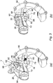
- FIGS 3 and 4 illustrate the tag delivery mechanism in more detail.
- Figures 3(a) and 3(b) show the mechanism being operated at the same time as a tag is being applied via the applicator jaws.
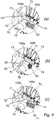
- Figures 4(a)-4(c) show the delivery member of the mechanism in more detail, where the tag guide has been removed for illustrative purposes.
- the tag delivery member is preferably a resilient pawl 70 having a free end 72 for engaging the tags 100 and a fixed end 74 attached to a cam follower 76.
- the follower 76 is rotatably and slidingly supported on a shaft 78 which is received in a locating aperture 80 in the outer surface of the guide 50.
- the shaft 78 has also been removed in figures 4(a)-4(c) for illustrative purposes.
- the cam follower 76 also has a guide member (not shown) which locates in a slot (not shown) in the guide 50 in order to guide the sliding follower 76 along the shaft 78.
- the slot has an elongate guide portion running in the direction of the applicator body 12, and a release portion located at the end of the guide portion closest to the applicator body 12.
- the release portion is a continuation of the slot which is substantially at right angles to the guide portion.
- the release portion allows the cam follower 76 and pawl 70 to be partially rotated about the shaft 78 into a release position where the pawl 70 is no longer in contact with the tags 100 in the guide 50.
- the tags 100 can thus be pulled back out of the guide 50 when the follower 76 and pawl 70 are in the release position.
- a biasing member 82 is located on the shaft 78 between the cam follower 76 and the locating aperture 80 and biases the follower 76 and pawl 70 towards the applicator body 12.
- a cam 90 is attached to the second end 30 of the lever 26 on the side of the lever closest to the tag delivery mechanism.
- the cam 90 may be elongate and have a first end 92 attached to the actuator and a second end 94 remote from the actuator.
- the cam 90 may have a first cam surface 96 proximate the first end 92 of the cam 90, and a second cam surface 98 proximate the second end 94 of the cam 90.
- the cam 90 operates in a cam plane Y which is substantially parallel with the plane X of the applicator jaws 18,20.
- the first cam surface 96 lies at a first angle relative to the cam plane Y
- the second cam surface 98 lies at a second angle relative to the cam plane Y
- the second angle is greater than the first angle.
- an angle between the cam plane Y and a tangent to any portion of the first cam surface is less than an angle between the cam plane Y and a tangent to any portion of the second cam surface.
- the free end 72 of the pawl has an engagement surface 71 and an indexing surface 73.
- the engagement surface 71 faces towards the applicator body 12, whilst the indexing surface 73 faces towards the tags 100 in the tag guide 50 but lies at an acute angle to both the engagement surface 71 and the direction of travel of the tags 100.
- the angled indexing surface 73 means that the free end 72 of the pawl 70 is consequently wedge-shaped, with the thinner end of the wedge facing away from the applicator body 12.
- FIGS. 5(a)-5(e) show side views of the applicator 10 during the various stages of a tag application operation. It will be apparent that the tags, tag guide and other components making up the tag delivery mechanism have been removed from the figure 5 illustrations for illustrative purposes.
- figure 5(a) shows the applicator 10 in its rest position.
- the second jaw 20 and lever 26 are being biased away from the first jaw 18 and body 12, respectively, by their respective biasing members (not shown). Consequently, the first and second link members 32,34 and the first and third link pins 33,39 are all aligned along the plane P.
- the tag delivery mechanism is in the position shown in figure 4(a) .
- Figure 5(b) shows the applicator 10 as the actuator lever 26 is pressed towards the body 12 in the direction of arrow D. Thanks to the previously described abutment surfaces (not shown in figure 5 ) of the link members 32,34 and the offset second link pin 37, the link members 32,34 and first and third link pins 33,39 remain aligned along a single plane P as the lever 26 travels towards the body 12. At the same time, the link members 32,34 begin to press the second jaw 20 towards the first jaw 18 against the biasing force of the second jaw biasing member. The second jaw 20 thus pivots about its pivot pin 22 towards the first jaw 18.
- Figure 5(c) shows the applicator 10 at the point at which a tag will be applied to an object or animal.
- the tag will have been folded over to such an extent that the projecting pin on the first body portion will have pierced the object or appendage and now be locked in the locking aperture on the second body portion of the tag.
- the link members 32,34 and link pins 33,39 remain aligned along a single plane P, but it will be noted that the projecting member 24 on upper surface of the second jaw 20 is now immediately adjacent the second link member 34 and link pin 37.
- Figure 5(e) shows the applicator with the lever 26 in the process of being released by the operator.
- the lever 26 is thus returning to its open, or rest, position in the direction of arrow E under the action of the biasing member located between the body 12 and the lever 26.
- the cam 90 rises and allows the cam follower 76 and pawl 70 to be pressed back towards the applicator jaws by the biasing member 82.
- This position is shown in figure 4(c) , where the engagement surface 71 of the pawl 70 is forcing the first tag 100a towards the jaws of the applicator under the action of the biasing member 82.
- the tag 100a will enter the jaws of the applicator as the applicator returns to the position shown in figure 5(a) , ready for the next tag to be applied.
- the progressive reduction in the angle A between the first and second guide surfaces 58,60 over the course of the guide 50 ensures that the tags are automatically folded to the desired application state as they enter the jaws 18,20 for application.
- the present invention provides an identification tag applicator where substantially flat tags and/or tags having a relatively large angle between their body portions (e.g. 135-180 degrees) can be loaded into a semi-automatic delivery mechanism which folds the tags as they pass through the tag guide.
- a semi-automatic delivery mechanism which folds the tags as they pass through the tag guide.
- the operator does not need to waste any of the available hand movement folding the tags in the applicator jaws to a point where the tag is ready to be applied. Instead, they can use all the available hand movement to get the tag to penetrate the object or appendage to be tagged, and to lock the tag thereto.
- the present invention also provides a relatively simple tag delivery mechanism, where the resilient pawl accurately engages each successive tag and delivers it to the applicator jaws.
- Linking the actuator lever and delivery mechanism via the cam and cam follower arrangement also ensures that application of a tag and delivery of the next tag into the applicator jaws is achieved in a single, "squeeze and release” action by an operator.
- the pivoting release action available to the cam follower and pawl means that the pawl can be quickly and simply disengaged from any tags in the guide.
- the tags can be pulled backwards out of the guide via the first end and the operator consequently does not need to apply all the tags in the guide before changing to a different type of tag, for example.
- a further advantage of the present invention is provided by the actuation link arrangement connecting the lever and second applicator jaw.
- This arrangement allows an extremely powerful application force to be applied to the applicator jaw, but also provides a very simple release mechanism in the form of the projecting member on the pivoting jaw. The release by the projecting member breaking the link is thus independent of the application mechanism, and consequently does not compromise the application power available. Furthermore, with only two link members connecting the lever and second jaw, the chances of malfunction or failure of the apparatus are significantly reduced compared with the relatively complex release arrangements disclosed in previous proposals.
- a modified embodiment of the present invention may be provided which incorporates the actuation link arrangement but not necessarily the tag guide and other components of the tag delivery mechanism.
- the present invention may also be provided as a single tag applicator without the need for the semi-automated tag delivery mechanism.
- the modified embodiment is as shown in Figures 5(a)-(e) and comprises the body 12 having a first end and a second end, as well as the pair of applicator jaws 18,20 attached to the first end of the body.
- a manually-operated actuator pivotably attached to the second end of the body 12 which is adapted to close the applicator jaws 18,20, and a first biasing member which biases the actuator towards a position in which the jaws 18,20 are open.
- the actuator itself comprises the lever 26 having a first end pivotably attached to the body 12, the first link member 32 pivotably attached to the pivotable applicator jaw 20, and the second link member 34 having a first end pivotably attached to the first link member 32, and a second end pivotably attached to the lever 26.
- This actuation link arrangement is connected together and operates as described above, wherein the first and second link members 32,34 may not pivot relative to one another through more than substantially 180 degrees, and the second applicator jaw 20 includes the projecting member 24 adapted to force the link members 32,34 to pivot relative to one another when the applicator jaws 18,20 reach the closed position.
- This modified embodiment may also comprise the tag delivery mechanism and guide arrangement described above if the semi-automated delivery arrangement was required.
- the tag guide which may form part of the present invention is preferably curved, whereby the free first end passes through the plane in which the applicator jaws lie
- the present invention is not limited to this arrangement.
- the guide may instead be substantially straight and extend out perpendicular to the applicator body.
- the changes in the internal geometry of the guide surfaces would be the same whatever the overall shape of the guide.
- the tag application mechanism of the preferred embodiment comprises a pair of applicator jaws and an actuator arrangement made up of a pivoting lever and a pair of link members.
- the pivoting second jaw could be replaced by a spring-loaded plunger, where the plunger would push the pin of the first portion of a part-folded tag through the object or appendage and into locking engagement with the locking aperture on the second portion of the tag.
- the plunger could be operated by an actuator in the form of a pivoting trigger instead of a lever.
- the tag delivery mechanism may comprise a delivery member in the form of a rotating gearwheel selectively rotated by the actuator.
- the gearwheel would include teeth to engage the tags in the tag guide, whereby rotation of the gearwheel by the actuator would engage and push the successive tags into the application mechanism.
Landscapes
- Life Sciences & Earth Sciences (AREA)
- Environmental Sciences (AREA)
- Birds (AREA)
- Zoology (AREA)
- Animal Husbandry (AREA)
- Biodiversity & Conservation Biology (AREA)
- Labeling Devices (AREA)
Claims (14)
- Ein Identifikationsetiketten-Applikator (10), der Folgendes beinhaltet:einen Körper (12), an dem ein Paar Applikatorbacken (18, 20) angebracht ist, wobei eine der Backen relativ zu dem Körper schwenkbar ist;einen manuell betätigten Aktuator, der schwenkbar an dem Körper (12) angebracht ist und angepasst ist, um die schwenkbare Applikatorbacke (20) zwischen einer offenen und einer geschlossenen Position zu bewegen;wobei der Aktuator Folgendes beinhaltet:einen Hebel (26), der ein erstes Hebelende (28), das schwenkbar an dem Körper (12) angebracht ist, und ein zweites Hebelende (30) aufweist;ein Hebelvorspannelement, das den Hebel (26) in Richtung einer ersten Position vorspannt, in der sich die schwenkbare Backe (20) in der offenen Position befindet;ein erstes Verbindungselement (32), das ein erstes Verbindungsende, das schwenkbar an der schwenkbaren Applikatorbacke (20) angebracht ist, und ein zweites Verbindungsende, das eine erste Verriegelungsoberfläche (40) aufweist, aufweist;dadurch gekennzeichnet, dassein zweites Verbindungselement (34) ein drittes Verbindungsende (38), das schwenkbar an dem zweiten Hebelende angebracht ist, und ein viertes Verbindungsende (36), das eine zweite Verriegelungsoberfläche (42) aufweist und das schwenkbar an dem zweiten Verbindungsende angebracht ist, aufweist;wobei, wenn sich der Hebel (26) in der ersten Position befindet, das erste und das zweite Verbindungselement in der gleichen Ebene liegen und die erste und die zweite Verriegelungsoberfläche (40, 42) aneinanderstoßen, um die Verbindungselemente in der gleichen Ebene zu halten, wenn der Hebel aus der ersten Position bewegt wird, und wobei das zweite und vierte Verbindungsende durch einen Verbindungsstift (37) verbunden sind, der von der Ebene (P) der Verbindungselemente (32, 34) versetzt ist; undwobei die schwenkbare Applikatorbacke (20) ein vorstehendes Element (24) umfasst, das angepasst ist, um die Verbindungselemente (32, 34) dazu zu zwingen, relativ zueinander um den Verbindungsstift (37) zu schwenken, sodass sich die Verbindungselemente aus der Ebene (P) bewegen, wenn die Applikatorbacken (18, 20) eine geschlossene Position erreichen.
- Applikator gemäß Anspruch 1, wobei die schwenkbare Applikatorbacke (20) durch ein Backenvorspannelement in Richtung der offenen Position vorgespannt ist.
- Applikator gemäß einem der vorhergehenden Ansprüche, wobei eine der ersten und zweiten Verriegelungsoberflächen (40, 42) ein magnetisches Element (41) unterbringt und die andere der ersten und zweiten Verriegelungsflächen einen Magneten (43) unterbringt, der angepasst ist, um das magnetische Element anzuziehen.
- Applikator gemäß einem der vorhergehenden Ansprüche, und ferner beinhaltend einen Etikettenabgabemechanismus, der angepasst ist, um eine Vielzahl von aufeinanderfolgenden Etiketten an die Applikatorbacken abzugeben, wobei der Abgabemechanismus Folgendes beinhaltet:ein Abgabeelement, das angepasst ist, um in aufeinanderfolgende Etiketten einzugreifen und diese in Richtung der Backen (18, 20) zu zwingen; undeine Etikettenführung (50), die angepasst ist, um die aufeinanderfolgenden Etiketten unter der Wirkung des Abgabeelements in die Applikatorbacken (18, 20) zu führen;wobei die Etikettenführung (50) ein erstes Ende (52), in das Etiketten geladen werden, ein zweites Ende (54), aus dem die Etiketten in die Backen (18, 20) eintreten, und eine innere Führungsoberfläche, die angepasst ist, um mindestens einen ersten Abschnitt jedes Etiketts relativ zu einem zweiten Abschnitt jedes Etiketts zu führen und zu falten, wenn das Etikett in Richtung des zweiten Endes der Führung hin fortschreitet, aufweist.
- Applikator gemäß Anspruch 4, wobei die innere Führungsoberfläche eine erste und eine zweite Führungsoberfläche (58, 60) beinhaltet und wobei ein Winkel, der von der ersten und der zweiten Führungsoberfläche definiert ist, an dem ersten Ende (52) der Führung zwischen 135 und 180 Grad liegt und sich an dem zweiten Ende (54) der Führung allmählich auf zwischen 80 und 135 Grad reduziert.
- Applikator gemäß Anspruch 5, wobei der Winkel zwischen der ersten und der zweiten Führungsoberfläche (58, 60) an dem ersten Ende (52) der Führung im Wesentlichen 180 Grad beträgt und der Winkel zwischen den Führungsoberflächen an dem zweiten Ende (54) der Führung zwischen 80 und 110 Grad beträgt.
- Applikator gemäß Anspruch 5 oder Anspruch 6, wobei die Etikettenführung ein Abdeckelement (62), das ein freies Ende (66) und ein festes Ende (64), das an die zweite Führungsoberfläche (60) angebracht ist, aufweist, beinhaltet, wobei ein Führungsschlitz (56) zwischen dem freien Ende des Abdeckelements und der ersten Führungsoberfläche (58) definiert ist.
- Applikator gemäß Anspruch 7, wobei das freie Ende (66) des Abdeckelements (62) eine Führungsrippe (68) umfasst, die angepasst ist, um mit der oder jeder Etikette in der Führung (50) in Eingriff zu kommen.
- Applikator gemäß einem der Ansprüche 4 bis 8, wobei die Applikatorbacken (18, 20) in einer Backenebene (X) liegen und die Etikettenführung (50) derart gekrümmt ist, dass das erste Ende (52) der Führung durch die Backenebene verläuft.
- Applikator gemäß einem der Ansprüche 4 bis 9, wobei das Abgabeelement durch den Aktuator betätigt wird, wobei der Aktuator die schwenkbare Applikatorbacke (20) in einer ersten Bewegung in die geschlossene Position bewegt und das Abgabeelement in einer zweiten Bewegung, die der ersten Bewegung folgt, betätigt.
- Applikator gemäß einem der Ansprüche 4 bis 10, wobei das Abgabeelement eine elastische Klinke (70) beinhaltet, die gleitend auf einer Welle (78) getragen wird und durch ein Klinkenvorspannelement (82) in Richtung der Applikatorbacken (18, 20) vorgespannt ist.
- Applikator gemäß Anspruch 11, wobei die Etikettenführung (50) einen Führungsschlitz umfasst, der angepasst ist, um die Gleitklinke (70) in Richtung der Applikatorbacken (18, 20) zu führen, und wobei die Klinke drehbar auf der Welle (78) getragen wird und der Führungsschlitz an einem Ende davon einen Freigabeabschnitt umfasst, wobei der Freigabeabschnitt im Wesentlichen senkrecht zu dem Führungsschlitz liegt, um zu ermöglichen, dass die Klinke selektiv auf der Welle aus dem Eingriff mit den Etiketten geschwenkt wird.
- Applikator gemäß Anspruch 11 oder Anspruch 12, wobei der Aktuator einen Nocken (90) umfasst, der angepasst ist, um das Abgabeelement während der ersten Bewegung gegen die Kraft des Klinkenvorspannelements (82) von den Applikatorbacken (18, 20) wegzudrücken.
- Applikator gemäß Anspruch 13, wobei der Nocken (90) länglich ist und ein erstes Ende (92), das an dem Aktuator angebracht ist, und ein zweites Ende (94), das von dem Aktuator entfernt liegt und angepasst ist, um auf das Abgabeelement einzuwirken, aufweist, und wobei der Nocken eine erste Nockenoberfläche (96) in der Nähe des ersten Endes des Nockens und eine zweite Nockenoberfläche (98) in der Nähe des zweiten Endes des Nockens aufweist, wobei der Nocken in einer Nockenebene (Y) tätigt ist, wobei die erste Nockenoberfläche in einem ersten Winkel relativ zu der Nockenebene liegt und die zweite Nockenoberfläche in einem zweiten Winkel relativ zu der Nockenebene liegt und der zweite Winkel größer als der erste Winkel ist.
Applications Claiming Priority (3)
| Application Number | Priority Date | Filing Date | Title |
|---|---|---|---|
| GBGB1004520.1A GB201004520D0 (en) | 2010-03-18 | 2010-03-18 | An improved identification tag applicator |
| PCT/GB2011/050527 WO2011114159A2 (en) | 2010-03-18 | 2011-03-17 | An improved identification tag applicator |
| EP11715729.7A EP2547198B8 (de) | 2010-03-18 | 2011-03-17 | Verbesserter applikator für informationsetiketten |
Related Parent Applications (2)
| Application Number | Title | Priority Date | Filing Date |
|---|---|---|---|
| EP11715729.7A Division EP2547198B8 (de) | 2010-03-18 | 2011-03-17 | Verbesserter applikator für informationsetiketten |
| EP11715729.7A Division-Into EP2547198B8 (de) | 2010-03-18 | 2011-03-17 | Verbesserter applikator für informationsetiketten |
Publications (2)
| Publication Number | Publication Date |
|---|---|
| EP2995196A1 EP2995196A1 (de) | 2016-03-16 |
| EP2995196B1 true EP2995196B1 (de) | 2019-05-08 |
Family
ID=42227921
Family Applications (2)
| Application Number | Title | Priority Date | Filing Date |
|---|---|---|---|
| EP11715729.7A Active EP2547198B8 (de) | 2010-03-18 | 2011-03-17 | Verbesserter applikator für informationsetiketten |
| EP15190590.8A Active EP2995196B1 (de) | 2010-03-18 | 2011-03-17 | Verbesserter applikator für informationsetiketten |
Family Applications Before (1)
| Application Number | Title | Priority Date | Filing Date |
|---|---|---|---|
| EP11715729.7A Active EP2547198B8 (de) | 2010-03-18 | 2011-03-17 | Verbesserter applikator für informationsetiketten |
Country Status (7)
| Country | Link |
|---|---|
| EP (2) | EP2547198B8 (de) |
| AU (1) | AU2011228842B2 (de) |
| DK (2) | DK2547198T3 (de) |
| ES (2) | ES2684919T3 (de) |
| GB (1) | GB201004520D0 (de) |
| NZ (2) | NZ627572A (de) |
| WO (1) | WO2011114159A2 (de) |
Families Citing this family (1)
| Publication number | Priority date | Publication date | Assignee | Title |
|---|---|---|---|---|
| GB201400732D0 (en) * | 2014-01-16 | 2014-03-05 | Roxan Developments Ltd | Identification tag applicator |
Family Cites Families (6)
| Publication number | Priority date | Publication date | Assignee | Title |
|---|---|---|---|---|
| FR1264837A (fr) * | 1960-08-09 | 1961-06-23 | Hauptner H | Pince pour l'insertion de marques en forme d'étrier dans les oreilles des animaux |
| FR2106705A5 (de) * | 1970-09-22 | 1972-05-05 | Chevillot Ets | |
| AU6105880A (en) * | 1979-08-09 | 1981-02-12 | Leslie Walter Dore | Ear tags |
| NZ195919A (en) * | 1980-12-22 | 1984-11-09 | Allflex Int | Ear tag applicator:cam plate controls closing speed of tag parts to give increased leverage during installation |
| GB0023238D0 (en) * | 2000-09-22 | 2000-11-01 | Edgar Martin F | Animal tag applicator |
| DK176909B1 (da) * | 2008-06-12 | 2010-04-19 | Ms2Solution Aps | Dyremærkningsindretning |
-
2010
- 2010-03-18 GB GBGB1004520.1A patent/GB201004520D0/en not_active Ceased
-
2011
- 2011-03-17 EP EP11715729.7A patent/EP2547198B8/de active Active
- 2011-03-17 ES ES11715729.7T patent/ES2684919T3/es active Active
- 2011-03-17 WO PCT/GB2011/050527 patent/WO2011114159A2/en not_active Ceased
- 2011-03-17 EP EP15190590.8A patent/EP2995196B1/de active Active
- 2011-03-17 NZ NZ627572A patent/NZ627572A/en not_active IP Right Cessation
- 2011-03-17 ES ES15190590T patent/ES2732315T3/es active Active
- 2011-03-17 DK DK11715729.7T patent/DK2547198T3/en active
- 2011-03-17 AU AU2011228842A patent/AU2011228842B2/en active Active
- 2011-03-17 DK DK15190590.8T patent/DK2995196T3/da active
- 2011-03-17 NZ NZ601915A patent/NZ601915A/en unknown
Non-Patent Citations (1)
| Title |
|---|
| None * |
Also Published As
| Publication number | Publication date |
|---|---|
| NZ601915A (en) | 2014-08-29 |
| AU2011228842A1 (en) | 2012-09-06 |
| WO2011114159A2 (en) | 2011-09-22 |
| ES2732315T3 (es) | 2019-11-21 |
| WO2011114159A3 (en) | 2011-11-10 |
| ES2684919T3 (es) | 2018-10-05 |
| EP2547198B8 (de) | 2018-07-25 |
| NZ627572A (en) | 2014-10-31 |
| DK2547198T3 (en) | 2018-08-20 |
| AU2011228842B2 (en) | 2015-07-16 |
| EP2547198A2 (de) | 2013-01-23 |
| DK2995196T3 (da) | 2019-07-01 |
| GB201004520D0 (en) | 2010-05-05 |
| EP2995196A1 (de) | 2016-03-16 |
| EP2547198B1 (de) | 2018-06-06 |
Similar Documents
| Publication | Publication Date | Title |
|---|---|---|
| EP2528431B1 (de) | Tiermarkenapplikator | |
| RU2452174C2 (ru) | Аппликатор для прикрепления бирки к животному и бирка для него | |
| DE69308398T2 (de) | Chirurgische zweiteilige Abbindeklammer und modularer Applikator für Abbindeklammern | |
| EP2511056B1 (de) | Sicherheits-Messer | |
| DE68917975T2 (de) | Leicht zugängliche Heftmaschine für metallische Klammern. | |
| DE3145489A1 (de) | Medizinisches geraet der scherenbauart zum anbringen mehrerer abbindeklemmen | |
| CA2762182A1 (en) | Animal tag applicator | |
| NL8101945A (nl) | Afbindinrichting. | |
| WO2014194383A1 (en) | Improvements in applicators for animal identification ear tags | |
| GB2055670A (en) | Ear tags and apparatus for ear tagging | |
| EP2547198B1 (de) | Verbesserter applikator für informationsetiketten | |
| DE2027794B2 (de) | Schliessvorrichtung fuer aus metallband bestehende verschnuerungen von packstuecken | |
| AU2015203340B2 (en) | An Improved Identification Tag Applicator | |
| EP1479610B1 (de) | Schweisskopf für eine Bandumreifungsmaschine | |
| DE4316769C1 (de) | Chirurgisches Stanzinstrument | |
| EP1780172B1 (de) | Drehdeckelöffner | |
| DE68910540T2 (de) | Gerät zum Anbringen von chirurgischen Klammern. | |
| DE9307621U1 (de) | Chirurgisches Stanzinstrument | |
| AT500136B1 (de) | Schneidevorrichtung | |
| DE2154894A1 (de) | Verschließvorrichtung für Beutel | |
| EP3682956B1 (de) | Spielzeug | |
| AT205001B (de) | Klammerheftgerät | |
| DE4108513C1 (en) | Crimping press tool with two movable jaws - has control element, coacting with transfer mechanism for actuating transport linkage | |
| CH248363A (de) | Maschine zum Binden von Paketen mittels Metallbändern. | |
| DE2731165A1 (de) | Vorrichtung zum aufeinanderfolgenden ausschieben von verschlussplomben fuer umreifungen |
Legal Events
| Date | Code | Title | Description |
|---|---|---|---|
| PUAI | Public reference made under article 153(3) epc to a published international application that has entered the european phase |
Free format text: ORIGINAL CODE: 0009012 |
|
| AC | Divisional application: reference to earlier application |
Ref document number: 2547198 Country of ref document: EP Kind code of ref document: P |
|
| AK | Designated contracting states |
Kind code of ref document: A1 Designated state(s): AL AT BE BG CH CY CZ DE DK EE ES FI FR GB GR HR HU IE IS IT LI LT LU LV MC MK MT NL NO PL PT RO RS SE SI SK SM TR |
|
| 17P | Request for examination filed |
Effective date: 20160909 |
|
| RBV | Designated contracting states (corrected) |
Designated state(s): AL AT BE BG CH CY CZ DE DK EE ES FI FR GB GR HR HU IE IS IT LI LT LU LV MC MK MT NL NO PL PT RO RS SE SI SK SM TR |
|
| RAP1 | Party data changed (applicant data changed or rights of an application transferred) |
Owner name: DATAMARS S.A. |
|
| RIN1 | Information on inventor provided before grant (corrected) |
Inventor name: DATAMARS S.A. |
|
| RAP1 | Party data changed (applicant data changed or rights of an application transferred) |
Owner name: DATAMARS S.A. |
|
| RIN1 | Information on inventor provided before grant (corrected) |
Inventor name: DATAMARS S.A. |
|
| GRAP | Despatch of communication of intention to grant a patent |
Free format text: ORIGINAL CODE: EPIDOSNIGR1 |
|
| STAA | Information on the status of an ep patent application or granted ep patent |
Free format text: STATUS: GRANT OF PATENT IS INTENDED |
|
| INTG | Intention to grant announced |
Effective date: 20181130 |
|
| RIN1 | Information on inventor provided before grant (corrected) |
Inventor name: EADIE, BRIAN |
|
| GRAS | Grant fee paid |
Free format text: ORIGINAL CODE: EPIDOSNIGR3 |
|
| GRAA | (expected) grant |
Free format text: ORIGINAL CODE: 0009210 |
|
| STAA | Information on the status of an ep patent application or granted ep patent |
Free format text: STATUS: THE PATENT HAS BEEN GRANTED |
|
| AC | Divisional application: reference to earlier application |
Ref document number: 2547198 Country of ref document: EP Kind code of ref document: P |
|
| AK | Designated contracting states |
Kind code of ref document: B1 Designated state(s): AL AT BE BG CH CY CZ DE DK EE ES FI FR GB GR HR HU IE IS IT LI LT LU LV MC MK MT NL NO PL PT RO RS SE SI SK SM TR |
|
| REG | Reference to a national code |
Ref country code: GB Ref legal event code: FG4D |
|
| REG | Reference to a national code |
Ref country code: CH Ref legal event code: EP Ref country code: AT Ref legal event code: REF Ref document number: 1128725 Country of ref document: AT Kind code of ref document: T Effective date: 20190515 |
|
| REG | Reference to a national code |
Ref country code: DE Ref legal event code: R096 Ref document number: 602011058919 Country of ref document: DE Ref country code: IE Ref legal event code: FG4D |
|
| REG | Reference to a national code |
Ref country code: DK Ref legal event code: T3 Effective date: 20190624 |
|
| REG | Reference to a national code |
Ref country code: NL Ref legal event code: MP Effective date: 20190508 |
|
| REG | Reference to a national code |
Ref country code: LT Ref legal event code: MG4D |
|
| REG | Reference to a national code |
Ref country code: GR Ref legal event code: EP Ref document number: 20190401953 Country of ref document: GR Effective date: 20191016 |
|
| PG25 | Lapsed in a contracting state [announced via postgrant information from national office to epo] |
Ref country code: NO Free format text: LAPSE BECAUSE OF FAILURE TO SUBMIT A TRANSLATION OF THE DESCRIPTION OR TO PAY THE FEE WITHIN THE PRESCRIBED TIME-LIMIT Effective date: 20190808 Ref country code: LT Free format text: LAPSE BECAUSE OF FAILURE TO SUBMIT A TRANSLATION OF THE DESCRIPTION OR TO PAY THE FEE WITHIN THE PRESCRIBED TIME-LIMIT Effective date: 20190508 Ref country code: NL Free format text: LAPSE BECAUSE OF FAILURE TO SUBMIT A TRANSLATION OF THE DESCRIPTION OR TO PAY THE FEE WITHIN THE PRESCRIBED TIME-LIMIT Effective date: 20190508 Ref country code: PT Free format text: LAPSE BECAUSE OF FAILURE TO SUBMIT A TRANSLATION OF THE DESCRIPTION OR TO PAY THE FEE WITHIN THE PRESCRIBED TIME-LIMIT Effective date: 20190908 Ref country code: SE Free format text: LAPSE BECAUSE OF FAILURE TO SUBMIT A TRANSLATION OF THE DESCRIPTION OR TO PAY THE FEE WITHIN THE PRESCRIBED TIME-LIMIT Effective date: 20190508 Ref country code: HR Free format text: LAPSE BECAUSE OF FAILURE TO SUBMIT A TRANSLATION OF THE DESCRIPTION OR TO PAY THE FEE WITHIN THE PRESCRIBED TIME-LIMIT Effective date: 20190508 Ref country code: AL Free format text: LAPSE BECAUSE OF FAILURE TO SUBMIT A TRANSLATION OF THE DESCRIPTION OR TO PAY THE FEE WITHIN THE PRESCRIBED TIME-LIMIT Effective date: 20190508 Ref country code: FI Free format text: LAPSE BECAUSE OF FAILURE TO SUBMIT A TRANSLATION OF THE DESCRIPTION OR TO PAY THE FEE WITHIN THE PRESCRIBED TIME-LIMIT Effective date: 20190508 |
|
| REG | Reference to a national code |
Ref country code: ES Ref legal event code: FG2A Ref document number: 2732315 Country of ref document: ES Kind code of ref document: T3 Effective date: 20191121 |
|
| PG25 | Lapsed in a contracting state [announced via postgrant information from national office to epo] |
Ref country code: LV Free format text: LAPSE BECAUSE OF FAILURE TO SUBMIT A TRANSLATION OF THE DESCRIPTION OR TO PAY THE FEE WITHIN THE PRESCRIBED TIME-LIMIT Effective date: 20190508 Ref country code: RS Free format text: LAPSE BECAUSE OF FAILURE TO SUBMIT A TRANSLATION OF THE DESCRIPTION OR TO PAY THE FEE WITHIN THE PRESCRIBED TIME-LIMIT Effective date: 20190508 Ref country code: BG Free format text: LAPSE BECAUSE OF FAILURE TO SUBMIT A TRANSLATION OF THE DESCRIPTION OR TO PAY THE FEE WITHIN THE PRESCRIBED TIME-LIMIT Effective date: 20190808 |
|
| REG | Reference to a national code |
Ref country code: AT Ref legal event code: MK05 Ref document number: 1128725 Country of ref document: AT Kind code of ref document: T Effective date: 20190508 |
|
| PG25 | Lapsed in a contracting state [announced via postgrant information from national office to epo] |
Ref country code: CZ Free format text: LAPSE BECAUSE OF FAILURE TO SUBMIT A TRANSLATION OF THE DESCRIPTION OR TO PAY THE FEE WITHIN THE PRESCRIBED TIME-LIMIT Effective date: 20190508 Ref country code: SK Free format text: LAPSE BECAUSE OF FAILURE TO SUBMIT A TRANSLATION OF THE DESCRIPTION OR TO PAY THE FEE WITHIN THE PRESCRIBED TIME-LIMIT Effective date: 20190508 Ref country code: RO Free format text: LAPSE BECAUSE OF FAILURE TO SUBMIT A TRANSLATION OF THE DESCRIPTION OR TO PAY THE FEE WITHIN THE PRESCRIBED TIME-LIMIT Effective date: 20190508 Ref country code: AT Free format text: LAPSE BECAUSE OF FAILURE TO SUBMIT A TRANSLATION OF THE DESCRIPTION OR TO PAY THE FEE WITHIN THE PRESCRIBED TIME-LIMIT Effective date: 20190508 Ref country code: EE Free format text: LAPSE BECAUSE OF FAILURE TO SUBMIT A TRANSLATION OF THE DESCRIPTION OR TO PAY THE FEE WITHIN THE PRESCRIBED TIME-LIMIT Effective date: 20190508 |
|
| REG | Reference to a national code |
Ref country code: DE Ref legal event code: R097 Ref document number: 602011058919 Country of ref document: DE |
|
| PG25 | Lapsed in a contracting state [announced via postgrant information from national office to epo] |
Ref country code: SM Free format text: LAPSE BECAUSE OF FAILURE TO SUBMIT A TRANSLATION OF THE DESCRIPTION OR TO PAY THE FEE WITHIN THE PRESCRIBED TIME-LIMIT Effective date: 20190508 |
|
| PLBE | No opposition filed within time limit |
Free format text: ORIGINAL CODE: 0009261 |
|
| STAA | Information on the status of an ep patent application or granted ep patent |
Free format text: STATUS: NO OPPOSITION FILED WITHIN TIME LIMIT |
|
| PG25 | Lapsed in a contracting state [announced via postgrant information from national office to epo] |
Ref country code: TR Free format text: LAPSE BECAUSE OF FAILURE TO SUBMIT A TRANSLATION OF THE DESCRIPTION OR TO PAY THE FEE WITHIN THE PRESCRIBED TIME-LIMIT Effective date: 20190508 |
|
| 26N | No opposition filed |
Effective date: 20200211 |
|
| PG25 | Lapsed in a contracting state [announced via postgrant information from national office to epo] |
Ref country code: PL Free format text: LAPSE BECAUSE OF FAILURE TO SUBMIT A TRANSLATION OF THE DESCRIPTION OR TO PAY THE FEE WITHIN THE PRESCRIBED TIME-LIMIT Effective date: 20190508 |
|
| PG25 | Lapsed in a contracting state [announced via postgrant information from national office to epo] |
Ref country code: SI Free format text: LAPSE BECAUSE OF FAILURE TO SUBMIT A TRANSLATION OF THE DESCRIPTION OR TO PAY THE FEE WITHIN THE PRESCRIBED TIME-LIMIT Effective date: 20190508 |
|
| PG25 | Lapsed in a contracting state [announced via postgrant information from national office to epo] |
Ref country code: MC Free format text: LAPSE BECAUSE OF FAILURE TO SUBMIT A TRANSLATION OF THE DESCRIPTION OR TO PAY THE FEE WITHIN THE PRESCRIBED TIME-LIMIT Effective date: 20190508 |
|
| REG | Reference to a national code |
Ref country code: CH Ref legal event code: PL |
|
| REG | Reference to a national code |
Ref country code: BE Ref legal event code: MM Effective date: 20200331 |
|
| PG25 | Lapsed in a contracting state [announced via postgrant information from national office to epo] |
Ref country code: LU Free format text: LAPSE BECAUSE OF NON-PAYMENT OF DUE FEES Effective date: 20200317 |
|
| PG25 | Lapsed in a contracting state [announced via postgrant information from national office to epo] |
Ref country code: LI Free format text: LAPSE BECAUSE OF NON-PAYMENT OF DUE FEES Effective date: 20200331 Ref country code: CH Free format text: LAPSE BECAUSE OF NON-PAYMENT OF DUE FEES Effective date: 20200331 |
|
| PG25 | Lapsed in a contracting state [announced via postgrant information from national office to epo] |
Ref country code: BE Free format text: LAPSE BECAUSE OF NON-PAYMENT OF DUE FEES Effective date: 20200331 |
|
| PG25 | Lapsed in a contracting state [announced via postgrant information from national office to epo] |
Ref country code: MT Free format text: LAPSE BECAUSE OF FAILURE TO SUBMIT A TRANSLATION OF THE DESCRIPTION OR TO PAY THE FEE WITHIN THE PRESCRIBED TIME-LIMIT Effective date: 20190508 Ref country code: CY Free format text: LAPSE BECAUSE OF FAILURE TO SUBMIT A TRANSLATION OF THE DESCRIPTION OR TO PAY THE FEE WITHIN THE PRESCRIBED TIME-LIMIT Effective date: 20190508 |
|
| PG25 | Lapsed in a contracting state [announced via postgrant information from national office to epo] |
Ref country code: MK Free format text: LAPSE BECAUSE OF FAILURE TO SUBMIT A TRANSLATION OF THE DESCRIPTION OR TO PAY THE FEE WITHIN THE PRESCRIBED TIME-LIMIT Effective date: 20190508 Ref country code: IS Free format text: LAPSE BECAUSE OF FAILURE TO SUBMIT A TRANSLATION OF THE DESCRIPTION OR TO PAY THE FEE WITHIN THE PRESCRIBED TIME-LIMIT Effective date: 20190908 |
|
| PGFP | Annual fee paid to national office [announced via postgrant information from national office to epo] |
Ref country code: IE Payment date: 20230327 Year of fee payment: 13 Ref country code: FR Payment date: 20230321 Year of fee payment: 13 Ref country code: DK Payment date: 20230330 Year of fee payment: 13 |
|
| PGFP | Annual fee paid to national office [announced via postgrant information from national office to epo] |
Ref country code: IT Payment date: 20230329 Year of fee payment: 13 Ref country code: GR Payment date: 20230330 Year of fee payment: 13 Ref country code: GB Payment date: 20230327 Year of fee payment: 13 Ref country code: DE Payment date: 20230327 Year of fee payment: 13 |
|
| PGFP | Annual fee paid to national office [announced via postgrant information from national office to epo] |
Ref country code: ES Payment date: 20230412 Year of fee payment: 13 |
|
| REG | Reference to a national code |
Ref country code: DE Ref legal event code: R119 Ref document number: 602011058919 Country of ref document: DE |
|
| REG | Reference to a national code |
Ref country code: DK Ref legal event code: EBP Effective date: 20240331 |
|
| GBPC | Gb: european patent ceased through non-payment of renewal fee |
Effective date: 20240317 |
|
| PG25 | Lapsed in a contracting state [announced via postgrant information from national office to epo] |
Ref country code: DE Free format text: LAPSE BECAUSE OF NON-PAYMENT OF DUE FEES Effective date: 20241001 |
|
| PG25 | Lapsed in a contracting state [announced via postgrant information from national office to epo] |
Ref country code: GR Free format text: LAPSE BECAUSE OF NON-PAYMENT OF DUE FEES Effective date: 20241004 |
|
| PG25 | Lapsed in a contracting state [announced via postgrant information from national office to epo] |
Ref country code: GB Free format text: LAPSE BECAUSE OF NON-PAYMENT OF DUE FEES Effective date: 20240317 |
|
| PG25 | Lapsed in a contracting state [announced via postgrant information from national office to epo] |
Ref country code: FR Free format text: LAPSE BECAUSE OF NON-PAYMENT OF DUE FEES Effective date: 20240331 |
|
| PG25 | Lapsed in a contracting state [announced via postgrant information from national office to epo] |
Ref country code: IE Free format text: LAPSE BECAUSE OF NON-PAYMENT OF DUE FEES Effective date: 20240317 |
|
| PG25 | Lapsed in a contracting state [announced via postgrant information from national office to epo] |
Ref country code: IE Free format text: LAPSE BECAUSE OF NON-PAYMENT OF DUE FEES Effective date: 20240317 Ref country code: GR Free format text: LAPSE BECAUSE OF NON-PAYMENT OF DUE FEES Effective date: 20241004 Ref country code: GB Free format text: LAPSE BECAUSE OF NON-PAYMENT OF DUE FEES Effective date: 20240317 Ref country code: FR Free format text: LAPSE BECAUSE OF NON-PAYMENT OF DUE FEES Effective date: 20240331 Ref country code: DE Free format text: LAPSE BECAUSE OF NON-PAYMENT OF DUE FEES Effective date: 20241001 |
|
| PG25 | Lapsed in a contracting state [announced via postgrant information from national office to epo] |
Ref country code: DK Free format text: LAPSE BECAUSE OF NON-PAYMENT OF DUE FEES Effective date: 20240331 |
|
| PG25 | Lapsed in a contracting state [announced via postgrant information from national office to epo] |
Ref country code: IT Free format text: LAPSE BECAUSE OF NON-PAYMENT OF DUE FEES Effective date: 20240317 |
|
| REG | Reference to a national code |
Ref country code: ES Ref legal event code: FD2A Effective date: 20250506 |
|
| PG25 | Lapsed in a contracting state [announced via postgrant information from national office to epo] |
Ref country code: ES Free format text: LAPSE BECAUSE OF NON-PAYMENT OF DUE FEES Effective date: 20240318 |