EP2995007B1 - Duplexer - Google Patents
Duplexer Download PDFInfo
- Publication number
- EP2995007B1 EP2995007B1 EP14723856.2A EP14723856A EP2995007B1 EP 2995007 B1 EP2995007 B1 EP 2995007B1 EP 14723856 A EP14723856 A EP 14723856A EP 2995007 B1 EP2995007 B1 EP 2995007B1
- Authority
- EP
- European Patent Office
- Prior art keywords
- radio frequency
- duplexer
- switch
- state
- output port
- Prior art date
- Legal status (The legal status is an assumption and is not a legal conclusion. Google has not performed a legal analysis and makes no representation as to the accuracy of the status listed.)
- Active
Links
Images
Classifications
-
- H—ELECTRICITY
- H04—ELECTRIC COMMUNICATION TECHNIQUE
- H04L—TRANSMISSION OF DIGITAL INFORMATION, e.g. TELEGRAPHIC COMMUNICATION
- H04L5/00—Arrangements affording multiple use of the transmission path
- H04L5/14—Two-way operation using the same type of signal, i.e. duplex
-
- H—ELECTRICITY
- H04—ELECTRIC COMMUNICATION TECHNIQUE
- H04B—TRANSMISSION
- H04B1/00—Details of transmission systems, not covered by a single one of groups H04B3/00 - H04B13/00; Details of transmission systems not characterised by the medium used for transmission
- H04B1/38—Transceivers, i.e. devices in which transmitter and receiver form a structural unit and in which at least one part is used for functions of transmitting and receiving
- H04B1/40—Circuits
- H04B1/44—Transmit/receive switching
- H04B1/48—Transmit/receive switching in circuits for connecting transmitter and receiver to a common transmission path, e.g. by energy of transmitter
-
- H—ELECTRICITY
- H04—ELECTRIC COMMUNICATION TECHNIQUE
- H04L—TRANSMISSION OF DIGITAL INFORMATION, e.g. TELEGRAPHIC COMMUNICATION
- H04L43/00—Arrangements for monitoring or testing data switching networks
- H04L43/16—Threshold monitoring
Definitions
- the present invention relates to a duplexer, in particular a duplexer for use with a radio frequency antenna.
- the present invention also relates to a radar system comprising such a duplexer, and also to a method of operating such a duplexer.
- a duplexer is a device that allows bi-directional communication over a common input/output port, which might be described as bi-directional communication over a single path.
- a duplexer alternately switches between transmit and receive states, which allows communication via a common input/output port and, for instance, connection to a single antenna or antenna array for transmission and reception of radio frequency signals.
- the switching between specific dedicated transmission and reception states is to prevent relatively high-power pulses of the transmitter from entering the receiver, which could damage or destroy the receiver.
- the duplexer In order to prevent damage to the receiver, the duplexer is typically kept in a transmit state for a deliberate pre-determined period of time after the transmission pulse has been generated, to ensure that the generated pulse cannot enter the receiver. Although this does indeed give a degree of protection to the receiver, this same period of protection also limits the speed at which the duplexer can be switched from a transmission state to a reception state.
- US2004/0259505 details a transition from transmit state to reception state based on a gate signal.
- a duplexer for a radio frequency antenna comprising: a radio frequency signal transmitter port arranged for connection to a radio frequency signal transmitter; a radio frequency signal receiver port arranged for connection to a radio frequency signal receiver; a switch arranged selectively to adopt either one of: a first state which connects the transmitter port to a common input/output port of the switch arranged for connection to a radio frequency antenna; and a second state which connects the receiver port to the common input/output port; a switch control unit arranged to monitor radio frequency power at the common input/output port and to receive a transmission gate signal; wherein the switch control unit is arranged to control the switch to adopt the first state upon receipt of the transmission gate signal, and, subsequently, to control the switch to adopt the second state when the monitored radio frequency power falls below a threshold level.
- the transmission gate signal may comprise a pulse.
- a transmission gate signal pulse width may be shorter than a radio frequency transmission pulse width.
- the switch control unit may be arranged to monitor radio frequency power at the common input/output port for a period of time sufficient to determine if the monitored power constitutes part of a transmission pulse.
- the switch control unit is arranged to control the switch to adopt the second state when the monitored radio frequency power falls below the threshold level for a period of time sufficient to determine if the monitored power constitutes part of a transmission pulse.
- the threshold level may be a level above which damage would result to the radio frequency receiver.
- the switch control unit may be arranged to monitor radio frequency power at a plurality of locations at the common input/output port.
- the switch control unit may be arranged to monitor radio frequency power at the common input/output port using one or more couplers, for example one or more tap couplers.
- the switch may comprise a PIN diode.
- the common input/output port may comprise, or be connected to, an antenna.
- a radar system comprising a duplexer according to an aspect of the present invention.
- a method of operating a duplexer for a radio frequency antenna comprising: a radio frequency signal transmitter port arranged for connection to a radio frequency signal transmitter; a radio frequency signal receiver port arranged for connection to a radio frequency signal receiver; a switch arranged selectively to adopt either one of: a first state which connects the transmitter port to a common input/output port of the switch arranged for connection to a radio frequency antenna; and a second state which connects the receiver port to the common input/output port; a switch control unit arranged to receive a transmission gate signal; wherein the switch control unit is arranged to control the switch to adopt the first state upon receipt of the transmission gate signal, the method comprising: monitoring radio frequency power at the common input/output port; and subsequent to the switch adopting the first state, controlling the switch to adopt the second state when the monitored radio frequency power falls below a threshold level.
- a duplexer, radar system or method substantially as herein described, or substantially as herein described with reference to the accompanying Figures, or substantially as shown in the accompanying Figures.
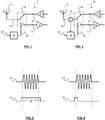
- FIG 1 schematically depicts a prior art duplexer (2) for a radio frequency antenna (4).
- the duplexer (2) comprises a radio frequency signal transmitter port (6) arranged for connection to a radio frequency signal transmitter (8).
- the duplexer (2) further comprises a radio frequency signal receiver port (10) arranged for connection to a radio frequency signal receiver (12).
- Port as used herein is an arrangement that allows a signal to be provided to/from the element in question, and might comprise a wire, a connector, or something more elaborate.
- the transmitter (8) and receiver (12) are schematically depicted by way of amplifiers, but it will be appreciated that the transmitter (8) and receiver (12) will in practice most likely comprise more components than this.
- the Figure is simply given as an aid to understanding the invention, with the amplifiers indicating the presence of a transmitter (8) and receiver (12).
- the duplexer (2) further comprises a switch (14).
- the switch (14) is arranged selectively to adopt either one of a first state and a second state.
- the switch (14) connects the transmitter port (6) to a common input/output port (16) of the switch (14), which is in turn arranged for connection to the radio frequency antenna (4).
- the switch (14) connects the receiver port (10) to the common input/output port (16), again for connection to the radio frequency antenna (4).
- the switch (14) may be, for instance, any switch that is capable of both handling the required radio frequency transmission load, and also switching at a speed that is desirable for appropriate transmission and reception of signals.
- the duplexer (2) further comprises a switch control unit (18) that is arranged to receive a transmission gate signal (20).
- the switch control unit (18) is arranged to control (22) the switch (14) to adopt the aforementioned first state upon receipt of the transmission gate signal (20).
- FIG. 2 schematically depicts the transmission gate signal (20) relative to a radio frequency transmission pulse (24) generated by the transmitter. It can be seen that the transmission gate signal (20) pulse width is greater than, and extends beyond, the radio frequency transmission (24) pulse width. This ensures that the duplexer is in a transmission state when a transmission signal is generated. However, there are also short periods (26) at the beginning and end of the transmission gate signal (20) pulse, where there is, in fact, no transmission signal.
- this period (26) ensures that the duplexer is in a ready state for transmission of the transmission signal (24).
- a short period (26) is provided before the transmission gate signal ends (or goes low). This latter period (26) is provided to ensure that there is little or no chance of the relatively high power transmission signal being connected to and thus damaging or destroying the sensitive receiver.
- this latter period (26) might indeed serve its purpose of providing this degree of protection, this period (26) also, and the same time, limits the speed at which the duplexer can switch from a transmission state to a receiving state.
- the limitation of the switching speed may not be problematic, for example when an echo of the transmission signal is received, expected to be received, or is usually received, after the transmission gate signal pulse has ended.
- this might not always be the case, especially if the echo is returned more quickly, for example, if a subject causing the echo is relatively close to the antenna. It is during this latter scenario that problems might arise.
- the problems discussed above with prior art duplexers may be at least partially obviated or mitigated.
- FIG 3 schematically depicts a duplexer (30) according to an example embodiment of the present invention.
- the duplexer (30) shares many of the features of the duplexer of the prior art, as shown in and described with reference to Figure 1 .
- the same features appearing in Figures 1 and 3 have been given the same reference numerals for consistency and clarity.
- the duplexer of Figure 3 comprises a monitor (32).
- the monitor (32) allows the switch control unit (18) to monitor radio frequency power at the common input/output port (16).
- the switching of the duplexer (30) from the transmission to the reception state is now dependent on, at least partially controlled by, this monitoring.
- the switch control unit (18) is, as with the prior art, arranged to control the switch (14) and duplexer (30) to adopt the transmission state upon receipt of the transmission gate signal (20).
- the switch control unit (18) is, additionally, subsequently arranged to control the switch (14) and duplexer (30) to adopt the reception state when the monitored radio frequency power falls below a threshold level. That is, the switching from the transmission state to the reception state is not determined or forced by termination of the transmission gate signal pulse (i.e. from a high to a low level), but is instead determined by the monitored radio frequency power at the common input/output port falling below a threshold level.
- Figure 4 schematically depicts principles associated with the operation of the duplexer of Figure 3 .
- the transmission gate signal (20) has a pulse width that does not extend beyond the transmission signal (24).
- the transmission gate signal (20) of Figure 4 has a pulse width that is shorter than the radio frequency transmission (24) pulse width.
- This sort of control regime is now allowed because, as already discussed above, it is no longer the termination of the transmission gate signal (20) pulse that determines the switching of the duplexer from the transmission to the reception state. Instead, it is the monitoring of the radio frequency power at the common input/output port falling below a threshold level that determines the switching of the duplexer from the transmission to the reception state.
- the change in state from transmission to reception is no longer determined in any way by a period during which the transmission signal deliberately holds the duplexer in a transmission state after termination of the transmission pulse in order to protect the receiver. Instead, the change in state is now determined by the speed at which the aforementioned monitoring and switching can take place. This can be achieved very quickly. This is particularly true if the switch of the duplexer comprises a PIN diode.
- a PIN diode is capable of handling the relatively high transmission loads of a transmission signal, and is also capable of switching quickly, thus serving the needs of the duplexer very well.
- the switching speed may be increased in comparison with prior art duplexers which rely on termination of a transmission gate signal to switch from a transmission to a reception state.
- an associated benefit of the example embodiment of the present invention is that the receiver is also implicitly protected by the described control regime. This is because the duplexer will only switch from a transmission state to a reception state when the monitored power is at a level which is determined (e.g., in advance) to be safe for the receiver of the duplexer - i.e. below a threshold level.
- monitoring and “threshold level” can be implemented in any particular manner, for example specific to the exact details of the transmission signal, transmission gate signal, circuit components, and so on. However, some general principles might nevertheless still apply.
- the monitoring may be facilitated by the use of one or more couplers, which may be referred to as, or be, tap couplers.
- a coupler may be an efficient way of determining the power at the common input/output port.
- the coupling might, in itself, be used to power or similarly provide a monitoring signal to the switch control unit. This may further increase monitoring and switching speeds.
- the monitoring may take place at a single location at the common input/output port. Alternatively, the monitoring may take place at a plurality of locations at the common input/output port. Use of a plurality of monitoring locations may provide a degree of redundancy if a monitor becomes damaged or unreliable, and/or might allow for a greater degree of certainty in the monitoring, and thus in determining whether switching should be undertaken.
- the duplexer may take place as soon as the monitored radio frequency power falls below a pre-determined threshold level.
- the nature of the transmission signal or similar may make this approach impractical, difficult to implement, or undesirable.
- the switch control unit may be arranged to control the switch to adopt the reception state when the monitored radio frequency power falls below the threshold value for a period of time to determine if the monitored power constitutes part of a transmission pulse.
- the time may be known in advance from knowledge of the transmission signal, for example its form, shape, duration, and the like.
- the threshold level will be a level above which level damage would result to the radio frequency receiver.
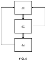
- Figure 5 shows a flowchart which depicts how an example embodiment of the duplexer may operate.
- the duplexer may be switched to a transmit state upon receipt of a transmission gate signal (40). Radio frequency power at a common input/output port of the duplexer is monitored (42). If the monitored radio frequency power does not fall below a threshold level, then the duplexer may be maintained in the transmit state (40), which may be achieved by not switching to the receive state. If the monitored radio frequency power does fall below a threshold level, then the duplexer may be switched from the transmit state to the receive state (44). The duplexer may be switched back to the transmit state by appropriate application of a transmission gate signal (40), ready for transmission of another transmission pulse.
- a transmission gate signal 40
- the duplexer described above may find use in a number of different applications, but may find particular use in a radar system where quickly switching from a transmission to a reception state is of particular importance, especially when subjects relatively close to the antenna of the radar system are to be detected and/or tracked.
Landscapes
- Engineering & Computer Science (AREA)
- Signal Processing (AREA)
- Computer Networks & Wireless Communication (AREA)
- Transceivers (AREA)
Priority Applications (2)
| Application Number | Priority Date | Filing Date | Title |
|---|---|---|---|
| EP14723856.2A EP2995007B1 (en) | 2013-05-10 | 2014-05-08 | Duplexer |
| PL14723856T PL2995007T3 (pl) | 2013-05-10 | 2014-05-08 | Duplekser |
Applications Claiming Priority (4)
| Application Number | Priority Date | Filing Date | Title |
|---|---|---|---|
| GB1308442.1A GB2513909A (en) | 2013-05-10 | 2013-05-10 | Duplexer |
| EP13275115.7A EP2802082A1 (en) | 2013-05-10 | 2013-05-10 | Duplexer |
| EP14723856.2A EP2995007B1 (en) | 2013-05-10 | 2014-05-08 | Duplexer |
| PCT/GB2014/051404 WO2014181111A1 (en) | 2013-05-10 | 2014-05-08 | Duplexer |
Publications (2)
| Publication Number | Publication Date |
|---|---|
| EP2995007A1 EP2995007A1 (en) | 2016-03-16 |
| EP2995007B1 true EP2995007B1 (en) | 2019-07-31 |
Family
ID=50721848
Family Applications (1)
| Application Number | Title | Priority Date | Filing Date |
|---|---|---|---|
| EP14723856.2A Active EP2995007B1 (en) | 2013-05-10 | 2014-05-08 | Duplexer |
Country Status (6)
| Country | Link |
|---|---|
| US (1) | US9692583B2 (pl) |
| EP (1) | EP2995007B1 (pl) |
| AU (1) | AU2014264424B2 (pl) |
| ES (1) | ES2745468T3 (pl) |
| PL (1) | PL2995007T3 (pl) |
| WO (1) | WO2014181111A1 (pl) |
Families Citing this family (1)
| Publication number | Priority date | Publication date | Assignee | Title |
|---|---|---|---|---|
| CN112929051A (zh) * | 2019-12-06 | 2021-06-08 | 上海新微技术研发中心有限公司 | 收发机前端开关自动控制方法 |
Family Cites Families (8)
| Publication number | Priority date | Publication date | Assignee | Title |
|---|---|---|---|---|
| US6314305B1 (en) * | 1998-12-10 | 2001-11-06 | Lucent Technologies Inc. | Transmitter/receiver for combined adaptive array processing and fixed beam switching |
| US6681100B1 (en) | 1999-03-15 | 2004-01-20 | Teletronics International, Inc. | Smart amplifier for time division duplex wireless applications |
| US7138885B2 (en) | 2002-03-22 | 2006-11-21 | Telefonaktiebolaget Lm Ericsson (Publ) | Transmit receive switch with high power protection |
| US20040077316A1 (en) | 2002-10-16 | 2004-04-22 | Wei Xiong | Use of power detection to control RX/TX switching |
| US20040259505A1 (en) * | 2003-06-19 | 2004-12-23 | Karthik Vasanth | Switch circuit especially suitable for use in wireless LAN applications |
| US7937063B1 (en) * | 2007-08-29 | 2011-05-03 | Clear Wireless Llc | Method and system for configuring a tower top low noise amplifier |
| US8027648B2 (en) | 2009-04-29 | 2011-09-27 | Lockheed Martin Corporation | Radio frequency power monitor |
| WO2013044481A1 (en) | 2011-09-29 | 2013-04-04 | Thomson Licensing | Method and apparatus for extending receiving dynamic range of rf transceiver in tdd system |
-
2014
- 2014-05-08 PL PL14723856T patent/PL2995007T3/pl unknown
- 2014-05-08 ES ES14723856T patent/ES2745468T3/es active Active
- 2014-05-08 EP EP14723856.2A patent/EP2995007B1/en active Active
- 2014-05-08 WO PCT/GB2014/051404 patent/WO2014181111A1/en not_active Ceased
- 2014-05-08 AU AU2014264424A patent/AU2014264424B2/en active Active
- 2014-05-08 US US14/890,337 patent/US9692583B2/en active Active
Non-Patent Citations (1)
| Title |
|---|
| None * |
Also Published As
| Publication number | Publication date |
|---|---|
| PL2995007T3 (pl) | 2019-12-31 |
| US20160182210A1 (en) | 2016-06-23 |
| ES2745468T3 (es) | 2020-03-02 |
| EP2995007A1 (en) | 2016-03-16 |
| AU2014264424A1 (en) | 2015-11-26 |
| WO2014181111A1 (en) | 2014-11-13 |
| AU2014264424B2 (en) | 2017-11-23 |
| US9692583B2 (en) | 2017-06-27 |
Similar Documents
| Publication | Publication Date | Title |
|---|---|---|
| EP4391668A3 (en) | Configuration information for an inactive state | |
| US9979423B2 (en) | Parallel connection method and device for multi-channel PD signals | |
| EP2026093B1 (en) | Transmit/receive module | |
| WO2014113247A3 (en) | Method and apparatus to reduce pa/device temperature by switching the antennas on a device | |
| CN106100675A (zh) | 一种射频前端装置、天线装置及移动终端 | |
| EP2995007B1 (en) | Duplexer | |
| GB2513909A (en) | Duplexer | |
| EP4122124B1 (en) | Time-division duplex (tdd) antenna system | |
| EP2802082A1 (en) | Duplexer | |
| US12341729B2 (en) | Time-division duplex (TDD) antenna system | |
| JP2013090263A (ja) | フェーズドアレーレーダ用受信回路およびフェーズドアレーレーダ用送受信モジュール | |
| CN110336571B (zh) | 一种具有自适应频率选择宽带高功率微波保护装置 | |
| KR100726232B1 (ko) | 시분할복신 무선통신시스템의 고주파 전단 장치 | |
| US10419551B2 (en) | Network device and auto detecting method for direct link thereof | |
| US10038477B2 (en) | Combined active and passive high-power RF protection circuit | |
| JP6379561B2 (ja) | Dme地上装置およびその運用停止防止方法 | |
| US8411601B2 (en) | Electromagnetic wave circuit disruptor and method | |
| JP5225113B2 (ja) | 通信装置 | |
| KR102538264B1 (ko) | 근접 궤환신호를 이용해 자가진단 및 방해물체 검출이 가능한 레이더 장치 및 그 동작 방법 | |
| WO2007018867A3 (en) | Methods, devices and systems for protecting rfid reader front ends | |
| CN106199533A (zh) | 一种高功率二次雷达收发机保护装置 | |
| TWI511479B (zh) | 用以接收及傳送無線訊號的天線系統 | |
| KR101870935B1 (ko) | 멀티밴드 반사신호 측정 장치 | |
| KR101198592B1 (ko) | 과전압 방지 회로 | |
| CN112910495A (zh) | 基于终端设备的通信模块选择方法和装置 |
Legal Events
| Date | Code | Title | Description |
|---|---|---|---|
| PUAI | Public reference made under article 153(3) epc to a published international application that has entered the european phase |
Free format text: ORIGINAL CODE: 0009012 |
|
| 17P | Request for examination filed |
Effective date: 20151204 |
|
| AK | Designated contracting states |
Kind code of ref document: A1 Designated state(s): AL AT BE BG CH CY CZ DE DK EE ES FI FR GB GR HR HU IE IS IT LI LT LU LV MC MK MT NL NO PL PT RO RS SE SI SK SM TR |
|
| AX | Request for extension of the european patent |
Extension state: BA ME |
|
| DAX | Request for extension of the european patent (deleted) | ||
| RIC1 | Information provided on ipc code assigned before grant |
Ipc: H04L 12/26 20060101ALI20190104BHEP Ipc: H04B 1/48 20060101AFI20190104BHEP Ipc: H04B 1/44 20060101ALI20190104BHEP Ipc: H04L 5/14 20060101ALI20190104BHEP |
|
| GRAP | Despatch of communication of intention to grant a patent |
Free format text: ORIGINAL CODE: EPIDOSNIGR1 |
|
| STAA | Information on the status of an ep patent application or granted ep patent |
Free format text: STATUS: GRANT OF PATENT IS INTENDED |
|
| INTG | Intention to grant announced |
Effective date: 20190408 |
|
| GRAS | Grant fee paid |
Free format text: ORIGINAL CODE: EPIDOSNIGR3 |
|
| GRAA | (expected) grant |
Free format text: ORIGINAL CODE: 0009210 |
|
| STAA | Information on the status of an ep patent application or granted ep patent |
Free format text: STATUS: THE PATENT HAS BEEN GRANTED |
|
| AK | Designated contracting states |
Kind code of ref document: B1 Designated state(s): AL AT BE BG CH CY CZ DE DK EE ES FI FR GB GR HR HU IE IS IT LI LT LU LV MC MK MT NL NO PL PT RO RS SE SI SK SM TR |
|
| REG | Reference to a national code |
Ref country code: CH Ref legal event code: EP Ref country code: GB Ref legal event code: FG4D |
|
| REG | Reference to a national code |
Ref country code: AT Ref legal event code: REF Ref document number: 1162041 Country of ref document: AT Kind code of ref document: T Effective date: 20190815 |
|
| REG | Reference to a national code |
Ref country code: IE Ref legal event code: FG4D |
|
| REG | Reference to a national code |
Ref country code: DE Ref legal event code: R096 Ref document number: 602014050830 Country of ref document: DE |
|
| REG | Reference to a national code |
Ref country code: NL Ref legal event code: FP |
|
| REG | Reference to a national code |
Ref country code: SE Ref legal event code: TRGR |
|
| REG | Reference to a national code |
Ref country code: LT Ref legal event code: MG4D |
|
| REG | Reference to a national code |
Ref country code: AT Ref legal event code: MK05 Ref document number: 1162041 Country of ref document: AT Kind code of ref document: T Effective date: 20190731 |
|
| PG25 | Lapsed in a contracting state [announced via postgrant information from national office to epo] |
Ref country code: HR Free format text: LAPSE BECAUSE OF FAILURE TO SUBMIT A TRANSLATION OF THE DESCRIPTION OR TO PAY THE FEE WITHIN THE PRESCRIBED TIME-LIMIT Effective date: 20190731 Ref country code: LT Free format text: LAPSE BECAUSE OF FAILURE TO SUBMIT A TRANSLATION OF THE DESCRIPTION OR TO PAY THE FEE WITHIN THE PRESCRIBED TIME-LIMIT Effective date: 20190731 Ref country code: AT Free format text: LAPSE BECAUSE OF FAILURE TO SUBMIT A TRANSLATION OF THE DESCRIPTION OR TO PAY THE FEE WITHIN THE PRESCRIBED TIME-LIMIT Effective date: 20190731 Ref country code: BG Free format text: LAPSE BECAUSE OF FAILURE TO SUBMIT A TRANSLATION OF THE DESCRIPTION OR TO PAY THE FEE WITHIN THE PRESCRIBED TIME-LIMIT Effective date: 20191031 Ref country code: PT Free format text: LAPSE BECAUSE OF FAILURE TO SUBMIT A TRANSLATION OF THE DESCRIPTION OR TO PAY THE FEE WITHIN THE PRESCRIBED TIME-LIMIT Effective date: 20191202 Ref country code: FI Free format text: LAPSE BECAUSE OF FAILURE TO SUBMIT A TRANSLATION OF THE DESCRIPTION OR TO PAY THE FEE WITHIN THE PRESCRIBED TIME-LIMIT Effective date: 20190731 Ref country code: NO Free format text: LAPSE BECAUSE OF FAILURE TO SUBMIT A TRANSLATION OF THE DESCRIPTION OR TO PAY THE FEE WITHIN THE PRESCRIBED TIME-LIMIT Effective date: 20191031 |
|
| PG25 | Lapsed in a contracting state [announced via postgrant information from national office to epo] |
Ref country code: RS Free format text: LAPSE BECAUSE OF FAILURE TO SUBMIT A TRANSLATION OF THE DESCRIPTION OR TO PAY THE FEE WITHIN THE PRESCRIBED TIME-LIMIT Effective date: 20190731 Ref country code: GR Free format text: LAPSE BECAUSE OF FAILURE TO SUBMIT A TRANSLATION OF THE DESCRIPTION OR TO PAY THE FEE WITHIN THE PRESCRIBED TIME-LIMIT Effective date: 20191101 Ref country code: IS Free format text: LAPSE BECAUSE OF FAILURE TO SUBMIT A TRANSLATION OF THE DESCRIPTION OR TO PAY THE FEE WITHIN THE PRESCRIBED TIME-LIMIT Effective date: 20191130 Ref country code: AL Free format text: LAPSE BECAUSE OF FAILURE TO SUBMIT A TRANSLATION OF THE DESCRIPTION OR TO PAY THE FEE WITHIN THE PRESCRIBED TIME-LIMIT Effective date: 20190731 Ref country code: LV Free format text: LAPSE BECAUSE OF FAILURE TO SUBMIT A TRANSLATION OF THE DESCRIPTION OR TO PAY THE FEE WITHIN THE PRESCRIBED TIME-LIMIT Effective date: 20190731 |
|
| REG | Reference to a national code |
Ref country code: ES Ref legal event code: FG2A Ref document number: 2745468 Country of ref document: ES Kind code of ref document: T3 Effective date: 20200302 |
|
| PG25 | Lapsed in a contracting state [announced via postgrant information from national office to epo] |
Ref country code: TR Free format text: LAPSE BECAUSE OF FAILURE TO SUBMIT A TRANSLATION OF THE DESCRIPTION OR TO PAY THE FEE WITHIN THE PRESCRIBED TIME-LIMIT Effective date: 20190731 |
|
| PG25 | Lapsed in a contracting state [announced via postgrant information from national office to epo] |
Ref country code: EE Free format text: LAPSE BECAUSE OF FAILURE TO SUBMIT A TRANSLATION OF THE DESCRIPTION OR TO PAY THE FEE WITHIN THE PRESCRIBED TIME-LIMIT Effective date: 20190731 Ref country code: DK Free format text: LAPSE BECAUSE OF FAILURE TO SUBMIT A TRANSLATION OF THE DESCRIPTION OR TO PAY THE FEE WITHIN THE PRESCRIBED TIME-LIMIT Effective date: 20190731 Ref country code: RO Free format text: LAPSE BECAUSE OF FAILURE TO SUBMIT A TRANSLATION OF THE DESCRIPTION OR TO PAY THE FEE WITHIN THE PRESCRIBED TIME-LIMIT Effective date: 20190731 |
|
| PG25 | Lapsed in a contracting state [announced via postgrant information from national office to epo] |
Ref country code: IS Free format text: LAPSE BECAUSE OF FAILURE TO SUBMIT A TRANSLATION OF THE DESCRIPTION OR TO PAY THE FEE WITHIN THE PRESCRIBED TIME-LIMIT Effective date: 20200224 Ref country code: SK Free format text: LAPSE BECAUSE OF FAILURE TO SUBMIT A TRANSLATION OF THE DESCRIPTION OR TO PAY THE FEE WITHIN THE PRESCRIBED TIME-LIMIT Effective date: 20190731 Ref country code: CZ Free format text: LAPSE BECAUSE OF FAILURE TO SUBMIT A TRANSLATION OF THE DESCRIPTION OR TO PAY THE FEE WITHIN THE PRESCRIBED TIME-LIMIT Effective date: 20190731 Ref country code: SM Free format text: LAPSE BECAUSE OF FAILURE TO SUBMIT A TRANSLATION OF THE DESCRIPTION OR TO PAY THE FEE WITHIN THE PRESCRIBED TIME-LIMIT Effective date: 20190731 |
|
| REG | Reference to a national code |
Ref country code: DE Ref legal event code: R097 Ref document number: 602014050830 Country of ref document: DE |
|
| PLBE | No opposition filed within time limit |
Free format text: ORIGINAL CODE: 0009261 |
|
| STAA | Information on the status of an ep patent application or granted ep patent |
Free format text: STATUS: NO OPPOSITION FILED WITHIN TIME LIMIT |
|
| PG2D | Information on lapse in contracting state deleted |
Ref country code: IS |
|
| PG25 | Lapsed in a contracting state [announced via postgrant information from national office to epo] |
Ref country code: IS Free format text: LAPSE BECAUSE OF FAILURE TO SUBMIT A TRANSLATION OF THE DESCRIPTION OR TO PAY THE FEE WITHIN THE PRESCRIBED TIME-LIMIT Effective date: 20191030 |
|
| 26N | No opposition filed |
Effective date: 20200603 |
|
| PG25 | Lapsed in a contracting state [announced via postgrant information from national office to epo] |
Ref country code: SI Free format text: LAPSE BECAUSE OF FAILURE TO SUBMIT A TRANSLATION OF THE DESCRIPTION OR TO PAY THE FEE WITHIN THE PRESCRIBED TIME-LIMIT Effective date: 20190731 |
|
| PG25 | Lapsed in a contracting state [announced via postgrant information from national office to epo] |
Ref country code: MC Free format text: LAPSE BECAUSE OF FAILURE TO SUBMIT A TRANSLATION OF THE DESCRIPTION OR TO PAY THE FEE WITHIN THE PRESCRIBED TIME-LIMIT Effective date: 20190731 Ref country code: CH Free format text: LAPSE BECAUSE OF NON-PAYMENT OF DUE FEES Effective date: 20200531 Ref country code: LI Free format text: LAPSE BECAUSE OF NON-PAYMENT OF DUE FEES Effective date: 20200531 |
|
| REG | Reference to a national code |
Ref country code: BE Ref legal event code: MM Effective date: 20200531 |
|
| PG25 | Lapsed in a contracting state [announced via postgrant information from national office to epo] |
Ref country code: LU Free format text: LAPSE BECAUSE OF NON-PAYMENT OF DUE FEES Effective date: 20200508 |
|
| PG25 | Lapsed in a contracting state [announced via postgrant information from national office to epo] |
Ref country code: IE Free format text: LAPSE BECAUSE OF NON-PAYMENT OF DUE FEES Effective date: 20200508 |
|
| PG25 | Lapsed in a contracting state [announced via postgrant information from national office to epo] |
Ref country code: BE Free format text: LAPSE BECAUSE OF NON-PAYMENT OF DUE FEES Effective date: 20200531 |
|
| PG25 | Lapsed in a contracting state [announced via postgrant information from national office to epo] |
Ref country code: MT Free format text: LAPSE BECAUSE OF FAILURE TO SUBMIT A TRANSLATION OF THE DESCRIPTION OR TO PAY THE FEE WITHIN THE PRESCRIBED TIME-LIMIT Effective date: 20190731 Ref country code: CY Free format text: LAPSE BECAUSE OF FAILURE TO SUBMIT A TRANSLATION OF THE DESCRIPTION OR TO PAY THE FEE WITHIN THE PRESCRIBED TIME-LIMIT Effective date: 20190731 |
|
| PG25 | Lapsed in a contracting state [announced via postgrant information from national office to epo] |
Ref country code: MK Free format text: LAPSE BECAUSE OF FAILURE TO SUBMIT A TRANSLATION OF THE DESCRIPTION OR TO PAY THE FEE WITHIN THE PRESCRIBED TIME-LIMIT Effective date: 20190731 |
|
| PGFP | Annual fee paid to national office [announced via postgrant information from national office to epo] |
Ref country code: NL Payment date: 20250423 Year of fee payment: 12 |
|
| PGFP | Annual fee paid to national office [announced via postgrant information from national office to epo] |
Ref country code: PL Payment date: 20250425 Year of fee payment: 12 Ref country code: DE Payment date: 20250423 Year of fee payment: 12 |
|
| PGFP | Annual fee paid to national office [announced via postgrant information from national office to epo] |
Ref country code: ES Payment date: 20250602 Year of fee payment: 12 |
|
| PGFP | Annual fee paid to national office [announced via postgrant information from national office to epo] |
Ref country code: IT Payment date: 20250423 Year of fee payment: 12 |
|
| PGFP | Annual fee paid to national office [announced via postgrant information from national office to epo] |
Ref country code: FR Payment date: 20250423 Year of fee payment: 12 |
|
| PGFP | Annual fee paid to national office [announced via postgrant information from national office to epo] |
Ref country code: SE Payment date: 20250423 Year of fee payment: 12 |
|
| PGFP | Annual fee paid to national office [announced via postgrant information from national office to epo] |
Ref country code: GB Payment date: 20260302 Year of fee payment: 13 |