EP2994930B1 - Schaltgerät mit einer einrichtung zum sprunghaften einschalten - Google Patents
Schaltgerät mit einer einrichtung zum sprunghaften einschalten Download PDFInfo
- Publication number
- EP2994930B1 EP2994930B1 EP13773196.4A EP13773196A EP2994930B1 EP 2994930 B1 EP2994930 B1 EP 2994930B1 EP 13773196 A EP13773196 A EP 13773196A EP 2994930 B1 EP2994930 B1 EP 2994930B1
- Authority
- EP
- European Patent Office
- Prior art keywords
- switching device
- switching
- limb
- lever
- locking part
- Prior art date
- Legal status (The legal status is an assumption and is not a legal conclusion. Google has not performed a legal analysis and makes no representation as to the accuracy of the status listed.)
- Active
Links
Images




Classifications
-
- H—ELECTRICITY
- H01—ELECTRIC ELEMENTS
- H01H—ELECTRIC SWITCHES; RELAYS; SELECTORS; EMERGENCY PROTECTIVE DEVICES
- H01H9/00—Details of switching devices, not covered by groups H01H1/00 - H01H7/00
- H01H9/20—Interlocking, locking, or latching mechanisms
-
- H—ELECTRICITY
- H01—ELECTRIC ELEMENTS
- H01H—ELECTRIC SWITCHES; RELAYS; SELECTORS; EMERGENCY PROTECTIVE DEVICES
- H01H1/00—Contacts
- H01H1/50—Means for increasing contact pressure, preventing vibration of contacts, holding contacts together after engagement, or biasing contacts to the open position
-
- H—ELECTRICITY
- H01—ELECTRIC ELEMENTS
- H01H—ELECTRIC SWITCHES; RELAYS; SELECTORS; EMERGENCY PROTECTIVE DEVICES
- H01H71/00—Details of the protective switches or relays covered by groups H01H73/00 - H01H83/00
- H01H71/10—Operating or release mechanisms
- H01H71/50—Manual reset mechanisms which may be also used for manual release
-
- H—ELECTRICITY
- H01—ELECTRIC ELEMENTS
- H01H—ELECTRIC SWITCHES; RELAYS; SELECTORS; EMERGENCY PROTECTIVE DEVICES
- H01H73/00—Protective overload circuit-breaking switches in which excess current opens the contacts by automatic release of mechanical energy stored by previous operation of a hand reset mechanism
- H01H73/02—Details
- H01H73/04—Contacts
- H01H73/045—Bridging contacts
-
- H—ELECTRICITY
- H01—ELECTRIC ELEMENTS
- H01H—ELECTRIC SWITCHES; RELAYS; SELECTORS; EMERGENCY PROTECTIVE DEVICES
- H01H2300/00—Orthogonal indexing scheme relating to electric switches, relays, selectors or emergency protective devices covered by H01H
- H01H2300/046—Orthogonal indexing scheme relating to electric switches, relays, selectors or emergency protective devices covered by H01H using snap closing mechanisms
-
- H—ELECTRICITY
- H01—ELECTRIC ELEMENTS
- H01H—ELECTRIC SWITCHES; RELAYS; SELECTORS; EMERGENCY PROTECTIVE DEVICES
- H01H71/00—Details of the protective switches or relays covered by groups H01H73/00 - H01H83/00
- H01H71/10—Operating or release mechanisms
- H01H71/50—Manual reset mechanisms which may be also used for manual release
- H01H71/56—Manual reset mechanisms which may be also used for manual release actuated by rotatable knob or wheel
Definitions
- the invention relates to a switching device having a device for sudden switching with an actuating mechanism which has an actuating element and is operatively connected via a transmission mechanism with a switch lock, which operates a shift lever via a further transmission mechanism, and with a contact arrangement comprising a fixed contact piece with contacts has, which is opposite lying to a movable contact piece with contacts, which is guided in a contact slide.
- Switching devices serve, among other things, the safe switching off in the event of a short circuit and thereby protect consumer installations.
- electrical or mechanical switching units are suitable for the operational manual switching of consumers as well as for the safe disconnection of a system from the mains during maintenance work or when changing the system. Electrical switching units are often operated electromagnetically.
- switching units are high-quality electrical switching devices with integrated protection for motors, lines, transformers and generators. They are used more closely at workstations with a lower switching frequency. Such switching units are suitable in addition to the short circuit protection for overload protection.
- an electrical switching unit switches off an electrical system safely.
- This provides a protection against overload.
- Each conductor flows through the stream, heats up more or less strongly. The heating depends on the ratio of the current to the conductor cross-section, the so-called current density.
- the current density must not be too large, otherwise by too high Heating may contaminate the conductor insulation or possibly cause a fire.
- switching units are used as overcurrent protective devices.
- Circuit breakers have two separate release mechanisms for overload and short-circuit protection. Both triggers are connected in series.
- the short-circuit protection is provided by an electrical release that works almost instantaneously. In the event of a short circuit, the electromagnetic release unlocks without delay a circuit breaker of the circuit breaker. A switching armature disconnects the contactor before the short-circuit current can reach its maximum value.
- switching units have a contact slide unit with a contact slide and a movable contact piece.
- the movable contact piece also has electrical contacts.
- switching units have first contacts to a power line. In an on state, the electrical contacts of the movable contact piece contact the fixed contacts of the switching unit. In the event of a short circuit, the electrical contacts of the movable contact piece are released from the fixed contacts, so that the flow of current is interrupted. Here, the movable contact is released from the fixed contacts.
- circuit breakers In addition to their protective functions as overload and short-circuit releases, as already mentioned above, circuit breakers also fulfill the normative switching on and off of motors. To prove this function, the circuit-breakers must be able to switch on ten times the rated motor current according to the product standard. In order to be able to guarantee this limit load, it is necessary for the circuit breaker to close the double interruption of the three current paths in the form of a movable bridge with two contact points and two fixed contact points, almost simultaneously and in a step function.
- the DE 19703977 C1 describes a switching device according to the preamble of claim 1. Accordingly, the object of the present invention is a switching device with a device for jumping To create switching, which avoids a contact lifting with possible contact welding.
- a switching device with a device for sudden switching which has an actuating mechanism which has an actuating element and is operatively connected via a transmission mechanism with a switch lock, which operates a shift lever via a further transmission mechanism, and has a contact arrangement which a fixed contact with contacts has, which is arranged opposite to a movable contact piece with contacts, which is guided in a contact slide
- the means for sudden switching comprises a switching mechanism arranged in the lever, which is arranged in operative connection to a locking member, which is operatively connected to a transmission member is, which acts on the movable contact piece of the contact arrangement.
- the invention is characterized in that the bevelled surface of the side wall of the transmission member defines a distance c and thus a certain, defined period of time in which the switching device is brought into the on position, so that the closure of the flow path operator-independent, by the dynamics of the contact apparatus and its contact load spring is determined.
- the three contact devices are pressed from movable and fixed contact pieces via a finger-shaped lever in the off position. This is associated with a defined distance a of the movable and fixed contact pieces from each other.
- the switch lock begins to release the transmission element and thus the contact device via its lever, which undergoes a rotational movement. After a lead, the lever forces the locking part to follow its rotational movement, since both parts have the same bearing point.
- the blocking member blocks the transmission member, so that the contact distance between the movable contact piece and fixed contact piece now maintains the distance b.
- the distance b is kept constant until the locking member has passed through the distance c on the transmission member. While the transfer member blocks the contactor, the lever continues to rotate. After passage of the distance c, the transmission member is released, so that the contact apparatus can close the current path independently of the rotational movement of the operating part. Due to the positive guidance of the locking part on the shift lever is a constant release of the transmission element.
- the essence of the invention is that the switch-on takes place independently of the rotational movement on the control panel.
- the distance c determines the time for which the contact distance b is held. During this period, the control panel is placed in the on position, so that the Closure of the current path is not determined by the rotational movement on the control panel, but by the dynamics of the contact apparatus and its contact load spring. This leads to the fact that there is no time difference when closing the individual current paths with each other.
- the contact load springs determine the dynamics of the movable contact pieces and not the rotary movement of the operating unit. Due to the close tolerance band of the contact load spring, the approximately constant weight of the bridges and the contact slide, there is an almost simultaneous closing of the flow path.
- the positive guidance between lever and locking part leads to a constant timing of the switch-on and to a small tolerance chain and thus to a high accuracy for the distance b.
- the respective switching device can be equipped device-specific with a corresponding locking part.
- the inventive device for sudden switching is characterized by three components that are in operative connection with each other.
- the lever according to the invention is part of the switching mechanism and preferably has two legs, which are interconnected via a connecting web.
- the legs are preferably at 90 ° to each other.
- the one leg has two larger and two smaller through holes, which are preferably arranged above and below one of the two larger holes and are designed to receive the two ends of a spring element.
- the other leg at the end of the connecting web is preferably formed over the entire surface.
- a further smaller leg is preferably arranged, which is connected via a further connecting web with the not full-surface leg.
- This third leg is preferably formed parallel to the other two legs and has a through hole in the assembled state of the switching device position equal to the lower, larger Through hole is arranged not full-scale leg.
- the blocking part according to the invention has a wedge-shaped component from which preferably two limbs protrude preferably on the same side, wherein one limb has a throughbore and is slightly rounded, and the other limb is full-surface and slightly wedge-shaped.
- a preferably semi-concentric projection is arranged at the top of the full-surface leg.
- the locking part is positioned on the lever, in which the through-hole of the leg is positioned by the locking part on the through hole of the small leg of the lever, so that lever and locking part are mounted in the same bearing point.
- the transmission element according to the invention has a preferably almost flat rear wall surface, from which two side walls protrude to the same side.
- the side walls each have a parallel to each other and spaced-apart area and a tapered region in which the side walls are formed to converge.
- a connecting web is formed at the transition between the parallel formed region of the side wall and the tapered region of the side wall.
- the tapered region of the side wall opens into two shorter, mutually parallel legs and two longer, mutually parallel legs, which are each spaced apart and are arranged below the connecting web and are formed in the switching device to the contact arrangement.
- the mutually parallel regions of the side wall are arranged above the connecting web in the direction of the switching mechanism.
- one of the two parallel side walls is smaller than the other and has a bevelled surface, which is in the switching device in operative connection with the wedge-shaped component of the blocking part.
- the tip of the wedge-shaped member of the locking member pulls over the tapered surface of the side wall of the transmission member until it comes to lie in the on position of the switching device with the back of the full-face leg of the locking member on the tapered surface of the side wall of the transmission member.
- the invention is characterized in that the switch-on takes place independently of the rotational movement on the control panel. Due to the sudden start, the contact load springs determine the dynamics of the moving contact pieces and not the rotation of the operating unit. Due to the close tolerance band of the contact load spring, the approximately constant weight of the bridges and the contact slide, there is an almost simultaneous closing of the current paths. As a result, arcing and welding can be avoided.
- the positive guidance according to the invention between lever and locking part leads to a constant time sequence of the switch-on process and to a small tolerance chain.
- the blocking part according to the invention can be designed device-specific.
- FIG. 1 an inventive lever 1 of a device for sudden switching of a switching device is shown.
- the lever 1 preferably has two legs 2, 3, which are connected to one another via a connecting web 4.
- the legs 2, 3 are preferably at 90 ° to each other.
- the leg 2 has two larger 5, 6 and two smaller 7, 8 through holes, which are preferably arranged above and below the through hole 6.
- the leg 3 at the end of the connecting web 4 is preferably formed over the entire surface.
- a further smaller leg 9 is preferably arranged, which is connected via a further connecting web 10 with the not ganzflambam leg 2.
- This third leg 9 is preferably arranged parallel to the other two legs 2, 3 and has a through hole 11 which is arranged in the assembled state of the switching device position equal to the lower, larger through hole 5 of the non-full-face leg 2.
- Fig. 2 shows the lever 1 according to the invention in a side view.
- Out Fig. 2 go through the through holes 5, 6, 7, 8 of the leg 2 clearly and the position of the legs 2, 3 to each other.
- Fig. 3 the lever 1 according to the invention is also shown in a further side view.
- the through holes 7, 8 on the leg 2 are used in the assembled state of the switching device for receiving the two ends of a spring element.
- FIG. 4 an inventive blocking part 12 of the device for sudden switching is shown.
- the blocking part 12 has a wedge-shaped component 13 from which preferably two legs 14, 15 protrude preferably on the same side, wherein the one leg 14 has a through bore 16 and is slightly rounded and the leg 15 is formed over its entire surface and slightly wedge-shaped.
- a preferably semi-concentric projection 17 is arranged at the top of the full-surface leg 15, a preferably semi-concentric projection 17 is arranged.
- the locking member 12 is positioned on the lever 1, in which the through hole 16 of the leg 14 of the locking member 12 is positioned on the through hole 11 of the small leg 9 of the lever 1, so that lever 1 and locking member 12 are mounted in the same bearing point.
- the transmission member 18 has a preferably almost flat rear wall surface 19, from which two side walls 20, 21 protrude to the same side.
- the side walls 20, 21 each have a mutually parallel and spaced-apart region 22, 23 and a respective tapered region 24, 25, in which the side walls 20, 21 are aligned with each other.
- a connecting web 26 is formed at the transition between the parallel formed portions 22, 23 of the side walls 20, 21 and the tapered portions 24, 25 of the side wall 20, 21, a connecting web 26 is formed.
- the tapered region 24, 25 of the side walls 20, 21, terminates in two shorter, mutually parallel legs 27, 28 and two longer, mutually parallel legs 29, 30, each spaced from each other and are disposed below the connecting web 26 and in Switching device are designed for contact arrangement.
- the mutually parallel regions 22, 23 of the side wall 20, 21 are arranged above the connecting web 26 in the direction of the switching mechanism.
- the side wall 21 is formed smaller than the side wall 20 and has a beveled surface 31, which is in the switching device in operative connection with the wedge-shaped member 13 of the locking member 12.
- the tip of the wedge-shaped component 13 of the locking member 12 extends beyond the tapered surface 31 of the side wall 21 of the transmission member 18, until in the switched-on position of the switching device, the back of the full-face leg 15 of the locking member 12 on the tapered surface 31 of the side wall 21 of the transmission member 18th to come to rest.
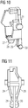
- the transmission member 18 according to the invention is shown in different perspective views, in particular from the Fig. 9 and the Fig. 10 the beveled surface 31 is clear.
- Fig. 12 is a switching mechanism 32 of a switching device, which is in operative connection with the device according to the invention for sudden switching, and a contact arrangement in the off position shown.
- the contact arrangement has a fixed contact piece 33 and a movable Schlt Culture 34, which is guided in a contact slide 35.
- the lever 1 is arranged, which is in operative connection to the locking member 12, which is spaced in the off position of the transmission member 18. In the off position and the movable contact piece 34 is spaced from the fixed contact piece 33.
- Fig. 13 is the switching mechanism 32 shown, which acts on the shift lever 36, which is in operative connection with the movable contact piece 34. In the in Fig. 13 shown position, the switched-off state of the switching device is shown.
- Fig. 14 shows the inventive device for sudden switching with contact arrangement in a schematic representation. Out Fig. 14 can be removed, the defined distance a, which is defined by the distance of the movable contact piece 34 from the fixed contact 33. It can be out Fig. 14 Furthermore, it can be seen that the blocking part 12 in the case of triggering passes through a rotation angle on the transmission member 18.
- Fig. 15 is the switching mechanism 32 shown with the inventive device for sudden switching and the contact arrangement in the open-hold position.
- the movable contact piece 34 is further spaced from the fixed contact piece 32, wherein the distance was reduced compared to the switched-off position of the switching device.
- lever 1 Arranged in the switching mechanism 32 lever 1 completes in the open-holding position a rotational movement through which the locking member 12 is moved in the direction of the tapered surface 31 of the transfer member 18.
- Fig. 16 the switch lock 32 is shown in its operative connection to the shift lever 36 in the open-hold position. Out Fig. 16 also the smaller distance of the switching pieces 33, 34 is apparent.
- Fig. 17 the inventive device for sudden switching with contact arrangements is shown in a schematic representation.
- Out Fig. 17 can be taken from the defined distance b, which is defined by the reduced distance of the movable contact piece 34 from the fixed contact 33 in the open-hold position. It can be out Fig. 17 also be taken that the locking member 12 has now moved to the tapered surface 31 of the transfer member 18. Furthermore, from the Fig. 17 the defined distance c are taken, which is defined by the chamfered surface 31 of the transmission member 18.
- Fig. 18 is the switching mechanism 32 of the switching device, which is in operative connection with the device according to the invention for sudden switching, and a contact arrangement in the on position shown.
- the movable contact piece 34 is now on the fixed contact 33.
- the lever 1 has completed a further rotational movement, by which the locking member 12 has been rotated further.
- the rotational movement of the locking member 12 is now the back of the leg 15 of the locking member 12 on the chamfered surface 31 of the transmission member 18th
- Fig. 19 is the switching mechanism 32 shown, which acts on the shift lever 36 in such a way that the shift lever 36 now has no Heidelberghebelberckenungsdazzling more with the contact slide.
- the movable contact piece 34 is now on the fixed contact 33.
- Fig. 20 shows the inventive device for sudden switching with contact arrangement in a schematic representation. From this Fig. 20 can be seen that the further rotation of the locking member 12 now causes the locking member 12 is disposed in the on position behind the tapered surface 31.
- the invention is characterized in that the switch-on takes place independently of the rotational movement on the control panel. Due to the sudden start, the contact load springs determine the dynamics of the moving contact pieces and not the rotation of the operating unit. Due to the close tolerance band of the contact load spring, the approximately constant weight of the bridges and the contact slide, there is an almost simultaneous closing of the current paths. As a result, arcing and welding can be avoided.
- the positive guidance according to the invention between lever and locking part leads to a constant time sequence of the switch-on process and to a small tolerance chain.
- the blocking part according to the invention can be designed device-specific.
Landscapes
- Rotary Switch, Piano Key Switch, And Lever Switch (AREA)
- Train Traffic Observation, Control, And Security (AREA)
- Slide Switches (AREA)
- Operating, Guiding And Securing Of Roll- Type Closing Members (AREA)
- Breakers (AREA)
Description
- Die Erfindung betrifft ein Schaltgerät mit einer Einrichtung zum sprunghaften Einschalten mit einer Betätigungsmechanik, die ein Betätigungselement aufweist und über eine Übertragungsmechanik mit einem Schaltschloss in Wirkverbindung steht, welches über eine weitere Übertragungsmechanik einen Schalthebel bedient, und mit einer Kontaktanordnung, die ein festes Schaltstück mit Kontakten aufweist, welches gegenüber liegend zu einem beweglichen Schaltstück mit Kontakten angeordnet ist, welches in einem Kontaktschieber geführt ist.
- Schaltgeräte, insbesondere Leistungsschalter, dienen unter Anderem dem sicheren Abschalten bei einem Kurzschluss und schützen dadurch Verbraucheranlagen. Ferner eignen sich elektrische oder mechanische Schalteinheiten für das betriebsmäßige manuelle Schalten von Verbrauchern sowie zur sicheren Trennung einer Anlage vom Stromnetz bei Wartungsarbeiten oder bei Änderungen an der Anlage. Elektrische Schalteinheiten werden häufig elektromagnetisch betrieben.
- Das heißt, derartige Schalteinheiten sind technisch hochwertige elektrische Schaltgeräte mit integriertem Schutz für Motoren, Leitungen, Transformatoren und Generatoren. Näheren Einsatz finden sie an Funktionsstellen mit geringerer Schalthäufigkeit. Derartige Schalteinheiten sind neben dem Kurzschlussschutz auch für den Überlastschutz geeignet.
- Im Fall eines Kurzschlusses schaltet eine elektrische Schalteinheit eine elektrische Anlage sicher ab. Somit bietet diese einen Sicherungsschutz vor Überlastung. Jeder Leiter durch den Strom fließt, erwärmt sich mehr oder weniger stark. Die Erwärmung hängt dabei vom Verhältnis der Stromstärke zum Stromleiterquerschnitt ab, der so genannten Stromdichte. Die Stromdichte darf nicht zu groß werden, da sonst durch zu hohe Erwärmung die Leiterisolationen verschmoren oder möglicherweise ein Brand ausgelöst werden kann. Um elektrische Anlagen gegen diese schädigenden Auswirkungen zu schützen, werden Schalteinheiten als Überstrom-Schutzeinrichtungen verwendet.
- Leistungsschalter weisen zwei voneinander getrennt wirkende Auslösemechanismen für den Überlast- und Kurzschlussschutz auf. Beide Auslöser sind in Reihe geschaltet. Den Schutz beim Kurzschluss übernimmt ein zeitlich nahezu unverzögert wirkender elektrischer Auslöser. Bei einem Kurzschluss entklinkt der elektromagnetische Auslöser unverzögert ein Schaltschloss des Leistungsschalters. Ein Schaltanker trennt das Schaltstück, ehe der Kurzschlussstrom seinen Höchstwert erreichen kann.
- Bekannte Schalteinheiten weisen eine Kontaktschiebereinheit mit einem Kontaktschieber und einem beweglichen Schaltstück auf. Das bewegliche Schaltstück weist ferner elektrische Kontakte auf. Ferner weisen derartige Schalteinheiten erste Kontakte zu einer Stromleitung auf. In einem eingeschalteten Zustand kontaktieren die elektrischen Kontakte des beweglichen Schaltstücks die festen Kontakte der Schalteinheit. Im Kurzschlussfall werden die elektrischen Kontakte des beweglichen Schaltstücks von den festen Kontakten gelöst, so dass der Stromfluss unterbrochen wird. Hierbei wird das bewegliche Schaltstück von den festen Kontakten gelöst.
- Leistungsschalter erfüllen neben ihren Schutzfunktionen als Überlast- und Kurzschlussauslöser, wie oben schon erwähnt, auch das normative Ein- und Ausschalten von Motoren. Zum Nachweis dieser Funktion müssen die Leistungsschalter nach der Produktnorm den zehnfachen Motornennstrom einschalten können. Um diese Grenzbelastung gewährleisten zu können ist es notwendig, dass der Leistungsschalter die Doppelunterbrechung der drei Strombahnen in Form jeweils einer beweglichen Brücke mit zwei Kontaktstellen und zwei festen Kontaktstellen, nahezu gleichzeitig und in einer Sprungfunktion schließt.
- Zur Realisierung dieser Funktion wird über eine Hand betätigte Mechanik in Form eines Betätigungselements, eines Schaltschlosses und einer Betätigungskette, der Kontaktapparat aus Kontaktschieber und einer beweglichen Brücke freigegeben. Die Freigabe erfolgt durch eine so genannte Schnelleinschaltung, die präzisiert formuliert eine spontane oder sprunghafte Einschaltung ist. Dabei werden die drei Kontaktsysteme durch eine Mechanik erst dann freigegeben, nachdem das Schaltschloss bereits eingeschaltet wurde. Nun bestimmt der Federspeicher in Form einer Kontaktlastfeder die Kinematik des Kontaktsystems beim Einschalten.
- Nach dem Auftreffen der Brücken auf den Festschaltstücken beschleunigt der Kontaktschieber, bis er an einem Anschlag reflektiert wird. Durch die Reflexion und der daraus resultierenden kinetischen Energie des Kontaktschiebers kommt es zu einem erneuten Öffnen des Kontaktsystems. Dies kann bei einem gleichzeitig erhöhten Strom in dieser Strombahn zu Verschweißungen führen.
- Die
DE 19703977 C1 beschreibt ein Schaltgerät nach dem Oberbegriff des Anspruchs 1. Demgemäß besteht die Aufgabe der vorliegenden Erfindung darin, ein Schaltgerät mit einer Einrichtung zum sprunghaften Einschalten zu schaffen, die ein Kontaktabheben mit möglicher Kontaktverschweißung vermeidet. - Diese Aufgabe wird erfindungsgemäß durch ein Schaltgerät mit den Merkmalen des Patentanspruchs 1 gelöst. Weitere Ausführungsbeispiele der Erfindung ergeben sich aus den Unteransprüchen, der Beschreibung sowie der Zeichnung.
- Erfindungsgemäß wird diese Aufgabe durch ein Schaltgerät mit einer Einrichtung zum sprunghaften Einschalten gelöst, die eine Betätigungsmechanik aufweist, die ein Betätigungselement aufweist und über eine Übertragungsmechanik mit einem Schaltschloss in Wirkverbindung steht, welches über eine weitere Übertragungsmechanik einen Schalthebel bedient, und eine Kontaktanordnung aufweist, die ein festes Schaltstück mit Kontakten aufweist, welches gegenüber liegend zu einem beweglichen Schaltstück mit Kontakten angeordnet ist, welches in einem Kontaktschieber geführt ist, wobei, die Einrichtung zum sprunghaften Einschalten einen im Schaltschloss angeordneten Hebel aufweist, der in Wirkverbindung zu einem Sperrteil angeordnet ist, das in Wirkverbindung zu einem Übertragungsglied steht, das auf das bewegliche Schaltstück der Kontaktanordnung wirkt. Die Erfindung zeichnet sich dabei dadurch aus, dass die abgeschrägte Fläche der Seitenwand des Übertragungsglieds einen Abstand c definiert und damit eine bestimmte, definierte Zeitspanne, in welcher das Schaltgerät in die eingeschaltete Position gebracht wird, so dass die Schliessung der Strombahn bedienerunabhängig, durch die Dynamik des Kontaktapparates und dessen Kontaktlast Feder bestimmt wird.
- Bei einem dreipoligen Schaltgerät, insbesondere bei einem Leistungsschalter, werden die drei Kontaktapparate aus beweglichen und festen Schaltstücken über einen fingerförmigen Schalthebel in die ausgeschaltete Stellung gedrückt. Damit verbunden ist ein definierter Abstand a der beweglichen und festen Schaltstücke voneinander. Beim Betätigen des Bedienelements beginnt das Schaltschloss über dessen Hebel, welcher eine Drehbewegung erfährt, das Übertragungsglied und somit den Kontaktapparat freizugeben. Nach einem Vorlauf zwingt der Hebel das Sperrteil seiner Drehbewegung zu folgen, da beide Teile den gleichen Lagerpunkt besitzen. Nach dem Durchlaufen des Drehwinkels blockiert das Sperrteil das Übertragungsglied, so dass der Kontaktabstand zwischen beweglichem Schaltstück und festem Schaltstück nun den Abstand b einhält. Der Abstand b wird so lange konstant gehalten, bis das Sperrteil den Abstand c am Übertragungsglied durchlaufen hat. Während das Übertragungsglied den Kontaktapparat blockiert, führt der Hebel seine Drehbewegung fort. Nach Durchlauf des Abstands c wird das Übertragungsglied freigegeben, so dass der Kontaktapparat unabhängig von der Drehbewegung des Bedienteils die Strombahn schließen kann. Durch die Zwangsführung des Sperrteils am Schalthebel erfolgt eine konstante Freigabe des Übertragungsglieds.
- Der Kern der Erfindung besteht darin, dass der Einschaltvorgang unabhängig von der Drehbewegung am Bedienteil erfolgt. Der Abstand c bestimmt die Zeit, für welche der Kontaktabstand b gehalten wird. Während dieser Zeitspanne wird das Bedienteil in die eingeschaltete Position gebracht, so dass die Schließung der Strombahn nicht durch die Drehbewegung am Bedienteil, sondern durch die Dynamik des Kontaktapparats und dessen Kontaktlastfeder bestimmt wird. Dies führt im Weiteren dazu, dass es keine zeitliche Abweichung beim Schließen der einzelnen Strombahnen untereinander gibt. Durch die spontane bzw. sprunghafte Einschaltung bestimmen die Kontaktlastfedern die Dynamik der beweglichen Schaltstücke und nicht die Drehbewegung des Bedienteils. Durch das enge Toleranzband der Kontaktlastfeder, dem annähernd konstanten Gewicht der Brücken sowie des Kontaktschiebers, erfolgt ein nahezu gleichzeitiges Schließen der Strombahn. Dadurch können Lichtbögen und Verschweißungen vermieden werden. Daraus resultiert eine Erhöhung des Einschaltbemessungsstroms. Die Zwangsführung zwischen Hebel und Sperrteil führt zu einem konstanten zeitlichen Ablauf des Einschaltvorgangs und zu einer kleinen Toleranzkette und somit zu einer hohen Genauigkeit für den Abstand b. Das jeweilige Schaltgerät kann gerätespezifisch mit einem entsprechenden Sperrteil bestückt werden.
- Die erfindungsgemäße Einrichtung zum sprunghaften Einschalten zeichnet sich durch drei Bauteile aus, die miteinander in Wirkverbindung stehen. Der erfindungsgemäße Hebel ist Teil des Schaltschlosses und weist vorzugsweise zwei Schenkel auf, die über einen Verbindungssteg miteinander verbunden sind. Die Schenkel stehen vorzugsweise im 90° Winkel zueinander. Der eine Schenkel weist zwei größere und zwei kleinere Durchbohrungen auf, die vorzugsweise oberhalb und unterhalb einer der beiden größeren Bohrungen angeordnet sind und zur Aufnahme der beiden Enden eines Federelements ausgebildet sind. Der andere Schenkel am Ende des Verbindungsstegs ist vorzugsweise vollflächig ausgebildet. Zwischen den Schenkeln ist vorzugsweise ein weiterer kleinerer Schenkel angeordnet, der über einen weiteren Verbindungssteg mit dem nicht vollflächigem Schenkel verbunden ist. Dieser dritte Schenkel ist vorzugsweise parallel zu den beiden anderen Schenkeln ausgebildet und weist eine Durchbohrung auf, die im zusammengebauten Zustand des Schaltgeräts positionsgleich zur unteren, größeren Durchbohrung des nicht vollflächigen Schenkels angeordnet ist.
- Das erfindungsgemäße Sperrteil weist ein keilförmiges Bauteil auf, aus welchem vorzugsweise zur gleichen Seite vorzugsweise zwei Schenkel herausragen, wobei der eine Schenkel eine Durchbohrung aufweist und leicht gerundet ausgebildet ist, und der andere Schenkel vollflächig und leicht keilförmig ausgebildet ist. An der Spitze des vollflächigen Schenkels ist ein vorzugsweise halbkonzentrischer Vorsprung angeordnet. Das Sperrteil wird am Hebel positioniert, in dem die Durchbohrung des Schenkels vom Sperrteil auf der Durchbohrung des kleinen Schenkels des Hebels positioniert wird, so dass Hebel und Sperrteil im gleichen Lagerpunkt gelagert sind. Durch diese gleiche Lagerung ist der vollflächige Schenkel des Sperrteils unterhalb des vollflächigen Schenkels des Hebels positioniert.
- Das erfindungsgemäße Übertragungsglied weist eine vorzugsweise nahezu ebene Rückwandfläche auf, aus welcher zur gleichen Seite zwei Seitenwandungen herausragen. Die Seitenwandungen weisen jeweils einen parallel zueinander und voneinander beabstandeten Bereich auf und einen zulaufenden Bereich, in welchem die Seitenwandungen aufeinander zulaufend ausgebildet sind. Am Übergang zwischen dem parallel ausgebildeten Bereich der Seitenwandung und dem zulaufenden Bereich der Seitenwandung ist ein Verbindungssteg ausgebildet. Der zulaufende Bereich der Seitenwandung mündet in zwei kürzere, parallel zueinander angeordnete Schenkel und zwei längere, parallel zueinander angeordnete Schenkel, die jeweils voneinander beabstandet sind und unterhalb vom Verbindungssteg angeordnet sind und im Schaltgerät zur Kontaktanordnung hin ausgebildet sind.
- Die parallel zueinander ausgebildeten Bereiche der Seitenwandung sind oberhalb vom Verbindungssteg angeordnet in Richtung des Schaltschlosses. Dabei ist eine der beiden parallelen Seitenwandungen kleiner als die andere ausgeführt und weist eine abgeschrägte Fläche auf, die im Schaltgerät in Wirkverbindung mit dem keilförmigen Bauteil des Sperrteils steht. Die Spitze des keilförmigen Bauteils des Sperrteils zieht über die abgeschrägte Fläche der Seitenwandung des Übertragungsglieds hinweg, bis sie in der eingeschalteten Position des Schaltgeräts mit der Rückseite des vollflächigen Schenkels des Sperrteils auf der abgeschrägten Fläche der Seitenwandung des Übertragungsglieds zu liegen kommt.
- Die Erfindung zeichnet sich dadurch aus, dass der Einschaltvorgang unabhängig von der Drehbewegung am Bedienteil erfolgt. Durch die sprunghafte Einschaltung bestimmen die Kontaktlastfedern die Dynamik der beweglichen Schaltstücke und nicht die Drehbewegung des Bedienteils. Durch das enge Toleranzband der Kontaktlastfeder, dem annähernd konstanten Gewicht der Brücken sowie des Kontaktschiebers, erfolgt ein nahezu gleichzeitiges Schließen der Strombahnen. Dadurch können Lichtbögen und Verschweißungen vermieden werden. Die erfindungsgemäße Zwangsführung zwischen Hebel und Sperrteil führt zu einem konstanten zeitlichen Ablauf des Einschaltvorgangs und zu einer kleinen Toleranzkette. Das erfindungsgemäße Sperrteil kann gerätespezifisch ausgelegt werden.
- Weitere Vorteile und Ausführungen der Erfindung werden anhand eines Ausführungsbeispiels sowie anhand der Zeichnung erläutert.
- Dabei zeigen:
-
Fig. 1 in einer perspektivischen Darstellung von vorn einen erfindungsgemäßen Hebel der Einrichtung zum sprunghaften Einschalten; -
Fig. 2 in einer perspektivischen Darstellung eine Seitenansicht des erfindungsgemäßen Hebels nachFig. 1 ; -
Fig. 3 in einer perspektivischen Darstellung eine weitere Ansicht des erfindungsgemäßen Hebels gemäß derFig. 1 und 2 ; -
Fig. 4 in einer perspektivischen Frontansicht ein erfindungsgemäßes Sperrteil der Einrichtung zum sprunghaften Einschalten; -
Fig. 5 in einer perspektivischen Seitenansicht das erfindungsgemäße Sperrteil nachFig. 4 ; -
Fig. 6 in einer weiteren perspektivischen Seitenansicht das erfindungsgemäße Sperrteil nachFig. 4 und 5 ; -
Fig. 7 in einer weiteren perspektivischen Seitenansicht das erfindungsgemäße Sperrteil nach denFig. 4 bis 6 ; -
Fig. 8 in einer perspektivischen Frontansicht ein erfindungsgemäßes Übertragungsglied der Einrichtung zum sprunghaften Einschalten eines Schaltgeräts; -
Fig. 9 in einer weiteren perspektivischen Frontansicht das erfindungsgemäße Übertragungsglied nachFig. 8 ; -
Fig. 10 in einer weiteren perspektivischen Seitenansicht das erfindungsgemäße Übertragungsglied nach denFig. 8 und 9 ; -
Fig. 11 in einer perspektivischen Rückansicht das erfindungsgemäße Übertragungsglied nach denFig. 8 bis 10 ; -
Fig. 12 in einer Schnittdarstellung ein Schaltschloss eines Schaltgeräts, welches in Wirkverbindung zu einer erfindungsgemäßen Einrichtung zum sprunghaften Einschalten steht, und eine Kontaktanordnung in der ausgeschalteten Position; -
Fig. 13 in einer Schnittdarstellung das Schaltschloss und die Kontaktanordnung nachFig. 12 in der ausgeschalteten Position; -
Fig. 14 in einer schematischen Darstellung die erfindungsgemäße Einrichtung zum sprunghaften Einschalten mit Kontaktanordnung in der ausgeschalteten Position; -
Fig. 15 in einer Schnittdarstellung ein Schaltschloss eines Schaltgeräts, welches in Wirkverbindung zu einer erfindungsgemäßen Einrichtung zum sprunghaften Einschalten steht, und eine Kontaktanordnung in der Offen-Halte-Position; -
Fig. 16 in einer Schnittdarstellung das Schaltschloss und die Kontaktanordnung nachFig. 15 in der Offen-Halte-Position; -
Fig. 17 in einer schematischen Darstellung die erfindungsgemäße Einrichtung zum sprunghaften Einschalten mit Kontaktanordnung in der Offen-Halte-Position; -
Fig. 18 in einer Schnittdarstellung ein Schaltschloss eines Schaltgeräts, welches in Wirkverbindung zu einer erfindungsgemäßen Einrichtung zum sprunghaften Einschalten steht, und eine Kontaktanordnung in der eingeschalteten Position; -
Fig. 19 in einer Schnittdarstellung das Schaltschloss und die Kontaktanordnung nachFig. 18 in der eingeschalteten Position; -
Fig. 20 in einer schematischen Darstellung die erfindungsgemäße Einrichtung zum sprunghaften Einschalten mit Kontaktanordnung in der eingeschalteten Position. - In
Fig. 1 ist ein erfindungsgemäßer Hebel 1 einer Einrichtung zum sprunghaften Einschalten eines Schaltgeräts dargestellt. Der Hebel 1 weist vorzugsweise zwei Schenkel 2, 3 auf, die über einen Verbindungssteg 4 miteinander verbunden sind. Die Schenkel 2, 3 stehen vorzugsweise im 90° Winkel zueinander. Der Schenkel 2 weist zwei größere 5 ,6 und zwei kleinere 7, 8 Durchbohrungen auf, die vorzugsweise oberhalb und unterhalb der Durchbohrung 6 angeordnet sind. Der Schenkel 3 am Ende des Verbindungsstegs 4 ist vorzugsweise vollflächig ausgebildet. Zwischen den Schenkeln 2, 3 ist vorzugsweise ein weiterer kleinerer Schenkel 9 angeordnet, der über einen weiteren Verbindungssteg 10 mit dem nicht vollflächigem Schenkel 2 verbunden ist. Dieser dritte Schenkel 9 ist vorzugsweise parallel zu den anderen beiden Schenkeln 2, 3 angeordnet und weist eine Durchbohrung 11 auf, die im zusammengebauten Zustand des Schaltgeräts positionsgleich zur unteren, größeren Durchbohrung 5 des nicht vollflächigen Schenkels 2 angeordnet ist. -
Fig. 2 zeigt den erfindungsgemäßen Hebel 1 in einer Seitenansicht. AusFig. 2 gehen die Durchbohrungen 5, 6, 7, 8 des Schenkels 2 deutlich hervor sowie die Stellung der Schenkel 2, 3 zueinander. - In
Fig. 3 ist der erfindungsgemäße Hebel 1 ebenfalls in einer weiteren Seitenansicht dargestellt. Die Durchbohrungen 7, 8 am Schenkel 2 werden im zusammen gebauten Zustand des Schaltgeräts zur Aufnahme der beiden Enden eines Federelements genutzt. - In
Fig. 4 ist ein erfindungsgemäßes Sperrteil 12 der Einrichtung zum sprunghaften Einschalten dargestellt. Das Sperrteil 12 weist ein keilförmiges Bauteil 13 auf, aus welchem vorzugsweise zur gleichen Seite vorzugsweise zwei Schenkel 14, 15 herausragen, wobei der eine Schenkel 14 eine Durchbohrung 16 aufweist und leicht gerundet ausgebildet ist und der Schenkel 15 vollflächig und leicht keilförmig ausgebildet ist. An der Spitze des vollflächigen Schenkels 15 ist ein vorzugsweise halbkonzentrischer Vorsprung 17 angeordnet. Das Sperrteil 12 wird am Hebel 1 positioniert, in dem die Durchbohrung 16 des Schenkels 14 des Sperrteils 12 auf der Durchbohrung 11 des kleinen Schenkels 9 des Hebels 1 positioniert wird, so dass Hebel 1 und Sperrteil 12 im gleichen Lagerpunkt gelagert sind. Durch diese gleiche Lagerung ist der vollflächige Schenkel 15 des Sperrteils 12 unterhalb des vollflächigen Schenkels 3 des Hebels 1 positioniert. - Die
Fig. 5 bis 7 zeigen unterschiedliche Seitenansichten des Sperrteils 12. Aus diesen Figuren geht insbesondere die Durchbohrung 16 des Schenkels 14 und der halbzylindrische Vorsprung 17 des Schenkels 15 eindeutig hervor sowie die keilförmige Ausbildung des keilförmigen Bauteils 13. - In
Fig. 8 ist ein erfindungsgemäßes Übertragungsglied 18 der Einrichtung zum sprunghaften Einschalten dargestellt. Das Übertragungsglied 18 weist eine vorzugsweise nahezu ebene Rückwandfläche 19 auf, aus welcher zur gleichen Seite zwei Seitenwandungen 20, 21 herausragen. Die Seitenwandungen 20, 21 weisen jeweils einen parallel zueinander und voneinander beabstandeten Bereich 22, 23 auf und einen jeweils zulaufenden Bereich 24, 25, in welchem die Seitenwandungen 20, 21 aufeinander zulaufend ausgerichtet sind. Am Übergang zwischen den parallel ausgebildeten Bereichen 22, 23 der Seitenwandungen 20, 21 und den zulaufenden Bereichen 24, 25 der Seitenwandung 20, 21, ist ein Verbindungssteg 26 ausgebildet. Der zulaufende Bereich 24, 25 der Seitenwandungen 20, 21, mündet in zwei kürzere, parallel zueinander angeordnete Schenkel 27, 28 und zwei längere, parallel zueinander angeordnete Schenkel 29, 30, die jeweils voneinander beabstandet sind und unterhalb vom Verbindungssteg 26 angeordnet sind und im Schaltgerät zur Kontaktanordnung hin ausgebildet sind. - Die parallel zueinander ausgerichteten Bereiche 22, 23 der Seitenwandung 20, 21, sind oberhalb vom Verbindungssteg 26 angeordnet in Richtung des Schaltschlosses. Die Seitenwandung 21 ist kleiner ausgebildet als die Seitenwandung 20 und weist eine abgeschrägte Fläche 31 auf, die im Schaltgerät in Wirkverbindung mit dem keilförmigen Bauteil 13 des Sperrteils 12 steht. Die Spitze des keilförmigen Bauteils 13 des Sperrteils 12 zieht über die abgeschrägte Fläche 31 der Seitenwandung 21 des Übertragungsglieds 18 hinweg, bis in der eingeschalteten Position des Schaltgeräts die Rückseite des vollflächigen Schenkels 15 des Sperrteils 12 auf der abgeschrägten Fläche 31 der Seitenwand 21 des Übertragungsglieds 18 zu liegen kommt.
- In den
Fig. 9 bis 11 ist das erfindungsgemäße Übertragungsglied 18 in unterschiedlichen perspektivischen Darstellungen dargestellt, insbesondere aus derFig. 9 und derFig. 10 geht die abgeschrägte Fläche 31 eindeutig hervor. - In
Fig. 12 ist ein Schaltschloss 32 eines Schaltgeräts, welches in Wirkverbindung zur erfindungsgemäßen Einrichtung zum sprunghaften Einschalten steht, und eine Kontaktanordnung in der ausgeschalteten Position dargestellt. Die Kontaktanordnung weist ein festes Schaltstück 33 und ein bewegliches Schltstück 34 auf, welches in einem Kontaktschieber 35 geführt ist. Im Schaltschloss 32 ist der Hebel 1 angeordnet, der in Wirkverbindung zum Sperrglied 12 steht, welches in der ausgeschalteten Position vom Übertragungsglied 18 beabstandet ist. In der ausgeschalteten Position ist auch das bewegliche Schaltstück 34 vom festen Schaltstück 33 beabstandet. - In
Fig. 13 ist das Schaltschloss 32 dargestellt, welches auf den Schalthebel 36 wirkt, der in Wirkverbindung zum beweglichen Schaltstück 34 steht. In der inFig. 13 dargestellten Position ist der ausgeschaltete Zustand des Schaltgeräts gezeigt. -
Fig. 14 zeigt die erfindungsgemäße Einrichtung zum sprunghaften Einschalten mit Kontaktanordnung in einer schematischen Darstellung. AusFig. 14 kann der definierte Abstand a entnommen werden, der durch den Abstand des beweglichen Schaltstücks 34 vom festen Schaltstück 33 definiert ist. Es kann ausFig. 14 weiterhin entnommen werden, dass das Sperrteil 12 im Auslösefall ein Drehwinkel auf das Übertragungsglied 18 zu durchläuft. - In
Fig. 15 ist das Schaltschloss 32 mit der erfindungsgemäßen Einrichtung zum sprunghaften Einschalten und der Kontaktanordnung in der Offen-Halte-Position dargestellt. In der Offen-Halte-Position ist das bewegliche Schaltstück 34 weiterhin vom festen Schaltstück 32 beabstandet, wobei der Abstand im Vergleich zur ausgeschalteten Position des Schaltgeräts verringert wurde. Der im Schaltschloss 32 angeordnete Hebel 1 vollzieht in der Offen-Halte-Position eine Drehbewegung, durch die auch das Sperrteil 12 bewegt wird und zwar in Richtung auf die abgeschrägte Fläche 31 des Übertragungsgliedes 18. In der Offen-Halte-Position zieht die Spitze des keilförmigen Bauteils 13 des Sperrteils 12 über die abgeschrägte Fläche 31 des Übertragungsglieds 18 hinweg. - In
Fig. 16 ist das Schaltschloss 32 in seiner Wirkverbindung zum Schalthebel 36 in der Offen-Halte-Position dargestellt. AusFig. 16 geht auch der geringere Abstand der Schaltstücke 33, 34 hervor. - In
Fig. 17 ist die erfindungsgemäße Einrichtung zum sprunghaften Einschalten mit Kontaktanordnungen in einer schematischen Darstellung gezeigt. AusFig. 17 kann der definierte Abstand b entnommen werden, der durch den verringerten Abstand des beweglichen Schaltstücks 34 vom festen Schaltstück 33 in der Offen-Halte-Position definiert ist. Es kann ausFig. 17 außerdem entnommen werden, dass das Sperrteil 12 sich nun auf die abgeschrägte Fläche 31 des Übertragungsgliedes 18 zu bewegt hat. Des Weiteren kann aus derFig. 17 der definierte Abstand c entnommen werden, der durch die abgeschrägte Fläche 31 des Übertragungsgliedes 18 definiert ist. - In
Fig. 18 ist das Schaltschloss 32 des Schaltgeräts, welches in Wirkverbindung zur erfindungsgemäßen Einrichtung zum sprunghaften Einschalten steht, und eine Kontaktanordnung in der eingeschalteten Position dargestellt. In der eingeschalteten Position liegt das bewegliche Schaltstück 34 nun auf dem festen Schaltstück 33. Es ist aus derFig. 18 weiterhin zu entnehmen, dass der Hebel 1 eine weitere Drehbewegung vollzogen hat, durch die auch das Sperrteil 12 weiter gedreht wurde. Durch die Drehbewegung des Sperrteils 12 liegt nun die Rückseite des Schenkels 15 des Sperrteils 12 auf der abgeschrägten Fläche 31 des Übertragungsgliedes 18. - In
Fig. 19 ist das Schaltschloss 32 dargestellt, welches auf den Schalthebel 36 wirkt und zwar in der Art, dass der Schalthebel 36 nun keinen Schalthebelberührungspunkt mehr mit dem Kontaktschieber aufweist. Das bewegliche Schaltstück 34 liegt nun auf dem festen Schaltstück 33 auf. -
Fig. 20 zeigt die erfindungsgemäße Einrichtung zum sprunghaften Einschalten mit Kontaktanordnung in einer schematischen Darstellung. Aus dieserFig. 20 kann entnommen werden, dass die weitere Drehbewegung des Sperrteils 12 nun dazu führt, dass das Sperrteil 12 in der eingeschalteten Position hinter der abgeschrägten Fläche 31 angeordnet ist. - Die Erfindung zeichnet sich dadurch aus, dass der Einschaltvorgang unabhängig von der Drehbewegung am Bedienteil erfolgt. Durch die sprunghafte Einschaltung bestimmen die Kontaktlastfedern die Dynamik der beweglichen Schaltstücke und nicht die Drehbewegung des Bedienteils. Durch das enge Toleranzband der Kontaktlastfeder, dem annähernd konstanten Gewicht der Brücken sowie des Kontaktschiebers, erfolgt ein nahezu gleichzeitiges Schließen der Strombahnen. Dadurch können Lichtbögen und Verschweißungen vermieden werden. Die erfindungsgemäße Zwangsführung zwischen Hebel und Sperrteil führt zu einem konstanten zeitlichen Ablauf des Einschaltvorgangs und zu einer kleinen Toleranzkette. Das erfindungsgemäße Sperrteil kann gerätespezifisch ausgelegt werden.
-
- 1
- Hebel
- 2
- Schenkel
- 3
- Schenkel
- 4
- Verbindungssteg
- 5
- Durchbohrung
- 6
- Durchbohrung
- 7
- Durchbohrung
- 8
- Durchbohrung
- 9
- Schenkel
- 10
- Verbindungssteg
- 11
- Durchbohrung
- 12
- Sperrteil
- 13
- Keilförmiges Bauteil
- 14
- Schenkel
- 15
- Schenkel
- 16
- Durchbohrung
- 17
- Halbkonzentrischer Vorsprung
- 18
- Übertragungsglied
- 19
- Rückwandfläche
- 20
- Seitenwand
- 21
- Seitenwand
- 22
- Paralleler Bereich
- 23
- Paralleler Bereich
- 24
- Zulaufender Bereich
- 25
- Zulaufender Bereich
- 26
- Verbindungssteg
- 27
- Kurzer Schenkel
- 28
- Kurzer Schenkel
- 29
- Langer Schenkel
- 30
- Langer Schenkel
- 31
- Abgeschrägte Fläche
- 32
- Schaltschloss
- 33
- Festes Schaltstück
- 34
- Bewegliches Schaltstück
- 35
- Kontaktschieber
- 36
- Schalthebel
Claims (12)
- Schaltgerät mit einer Einrichtung zum sprunghaften Ein schalten aufweisend:- eine Betätigungsmechanik, die ein Betätigungselement aufweist und über eine Übertragungsmechanik mit einem Schaltschloss (32) in Wirkverbindung steht, welches über eine weitere Übertragungsmechanik einen Schalthebel (36) bedient;- Eine Kontaktanordnung, die ein festes Schaltstück (33) mit Kontakten aufweist, welches gegenüber liegend zu einem beweglichen Schaltstück (34) mit Kontakten angeordnet ist, welches in einem Kontaktschieber (35) geführt ist,wobei, die im Schaltschloss (32) angeordnete Einrichtung zum sprunghaften Einschalten einen Hebel (1) aufweist, der in Wirkverbindung zu einem Sperrteil (12) angeordnet ist, das in Wirkverbindung zu einem Übertragungsglied (18) steht, das auf das bewegliche Schaltstück (34) der Kontaktanordnung wirkt, dadurch gekennzeichnet, dass die abgeschrägte Fläche (31) der Seitenwand (21) des Übertragungsglieds (18) einen Abstand c definiert und damit eine bestimmte, definierte Zeitspanne, in welcher das Schaltgerät in die eingeschaltete Position gebracht wird, so dass die Schließung der Strombahn bedienerunabhängig, durch die Dynamik des Kontaktapparates und dessen Kontaktlast Feder bestimmt ist.
- Schaltgerät nach Anspruch 1, dadurch gekennzeichnet, dass der Hebel (1) zwei Schenkel (2,3) aufweist, die über einen Verbindungssteg (4) miteinander verbunden sind.
- Schaltgerät nach Anspruch 2, dadurch gekennzeichnet, dass die Schenkel (2,3) im 90° Winkel zueinander angeordnet sind.
- Schaltgerät nach Anspruch 2 oder 3, dadurch gekennzeichnet, dass der Schenkel (2) zwei größere (5,6) und zwei kleinere Durchbohrungen (7,8) aufweist, die oberhalb und unterhalb der größeren Durchbohrung (8) angeordnet sind.
- Schaltgerät nach einem der vorhergehenden Ansprüche 2 bis 4, dadurch gekennzeichnet, dass zwischen den Schenkeln (2,3) ein weiterer Schenkel (9) angeordnet ist, der über einen Verbindungssteg (10) mit dem Schenkel (2) verbunden ist.
- Schaltgerät nach Anspruch 5, dadurch gekennzeichnet, dass der Schenkel (9) parallel zu den beiden Schenkeln (2,3) ausgebildet ist und eine Durchbohrung (11) aufweist, die im zusammen gebauten Zustand des Schaltgeräts positionsgleich zur Durchbohrung (5) des Schenkels (2) angeordnet ist.
- Schaltgerät nach einem der vorhergehenden Ansprüche 1 bis 6, dadurch gekennzeichnet, dass das Sperrteil (12) ein keilförmiges Bauteil (13) aufweist, aus welchem zwei Schenkel (14,15) zur gleichen Seite herausragen.
- Schaltgerät nach Anspruch 7, dadurch gekennzeichnet, dass der Schenkel (14) des Sperrteils (12) eine Durchbohrung (16) aufweist.
- Schaltgerät nach einem der vorhergehenden Ansprüche 1 bis 8, dadurch gekennzeichnet, dass das Sperrteil (12) am Hebel (1) positioniert ist, in dem die Durchbohrung (16) des Schenkels (14) am Sperrteil (12) auf der Durchbohrung (11) des Schenkels (9) des Hebels (1) gelagert ist, so dass Hebel (1) und Sperrteil (12) im gleichen Lagerpunkt gelagert sind.
- Schaltgerät nach einem der vorhergehenden Ansprüche 1 bis 9, dadurch gekennzeichnet, dass das Übertragungsglied (18) eine Seitenwand (21) mit einer abgeschrägten Fläche (31) aufweist, die im Schaltgerät in Wirkverbindung mit dem keilförmigen Bauteil (13) des Sperrteils (12) steht.
- Schaltgerät nach Anspruch 10, dadurch gekennzeichnet, dass die Spitze des keilförmigen Bauteils (13) des Sperrteils (12) im betätigten Zustand des Schaltgeräts über eine abgeschrägte Fläche (31) des Übertragungsglieds (18) hinweg gleitet und anschließend in der eingeschalteten Position die Rückseite des Schenkels (15) des Sperrteils (12) auf der abgeschrägten Fläche (31) der Seitenwand (21) des Übertragungsglieds (18) zu liegen kommt.
- Schaltgerät nach einem der vorhergehenden Ansprüche 1 bis 11, dadurch gekennzeichnet, dass das Schaltgerät ein Leistungsschalter ist.
Applications Claiming Priority (1)
| Application Number | Priority Date | Filing Date | Title |
|---|---|---|---|
| PCT/EP2013/069972 WO2015043632A1 (de) | 2013-09-25 | 2013-09-25 | Schaltgerät mit einer einrichtung zum sprunghaften einschalten |
Publications (2)
| Publication Number | Publication Date |
|---|---|
| EP2994930A1 EP2994930A1 (de) | 2016-03-16 |
| EP2994930B1 true EP2994930B1 (de) | 2017-11-15 |
Family
ID=49303952
Family Applications (1)
| Application Number | Title | Priority Date | Filing Date |
|---|---|---|---|
| EP13773196.4A Active EP2994930B1 (de) | 2013-09-25 | 2013-09-25 | Schaltgerät mit einer einrichtung zum sprunghaften einschalten |
Country Status (5)
| Country | Link |
|---|---|
| US (1) | US9734960B2 (de) |
| EP (1) | EP2994930B1 (de) |
| CN (1) | CN105359246B (de) |
| BR (1) | BR112016002051B1 (de) |
| WO (1) | WO2015043632A1 (de) |
Families Citing this family (3)
| Publication number | Priority date | Publication date | Assignee | Title |
|---|---|---|---|---|
| DE102016217225A1 (de) * | 2016-09-09 | 2018-03-15 | Siemens Aktiengesellschaft | Schaltschloss für ein Niederspannungsschutzgerät |
| DE102016217197A1 (de) * | 2016-09-09 | 2018-03-15 | Siemens Aktiengesellschaft | Schaltschloss für ein Niederspannungsschutzgerät |
| FR3074355B1 (fr) * | 2017-11-28 | 2020-12-18 | Schneider Electric Ind Sas | Dispositif de coupure d'un courant electrique |
Family Cites Families (7)
| Publication number | Priority date | Publication date | Assignee | Title |
|---|---|---|---|---|
| FR2626104B1 (fr) * | 1988-01-20 | 1995-05-24 | Hager Electro | Perfectionnement aux interrupteurs a coupure automatique, notamment aux interrupteurs differentiels et disjoncteurs |
| JPH02100229A (ja) * | 1988-10-06 | 1990-04-12 | Mitsubishi Electric Corp | 遠隔操作式回路遮断器 |
| DE9206137U1 (de) * | 1992-05-07 | 1993-09-09 | Siemens AG, 80333 München | Leistungsschalter mit einem Schaltschloß |
| DE19703977C1 (de) * | 1997-02-03 | 1998-05-14 | Siemens Ag | Schaltgerät mit Schnelleinschaltung |
| FR2907596B1 (fr) * | 2006-10-18 | 2009-01-23 | Areva T & D Sa | Dispositif de commande d'un appareillage electrique |
| EP2023368A1 (de) * | 2007-08-06 | 2009-02-11 | Siemens Aktiengesellschaft | Elektromechanischer Leistungsschalter mit integrierter, aber separat realisierter Trennerfunktion |
| DE102010014428A1 (de) | 2010-04-01 | 2011-10-06 | Siemens Aktiengesellschaft | Schalter, insbesondere Leistungsschalter |
-
2013
- 2013-09-25 US US15/021,120 patent/US9734960B2/en active Active
- 2013-09-25 CN CN201380077922.6A patent/CN105359246B/zh active Active
- 2013-09-25 WO PCT/EP2013/069972 patent/WO2015043632A1/de not_active Ceased
- 2013-09-25 BR BR112016002051-0A patent/BR112016002051B1/pt active IP Right Grant
- 2013-09-25 EP EP13773196.4A patent/EP2994930B1/de active Active
Non-Patent Citations (1)
| Title |
|---|
| None * |
Also Published As
| Publication number | Publication date |
|---|---|
| BR112016002051A2 (pt) | 2017-08-01 |
| WO2015043632A1 (de) | 2015-04-02 |
| US9734960B2 (en) | 2017-08-15 |
| EP2994930A1 (de) | 2016-03-16 |
| US20160225547A1 (en) | 2016-08-04 |
| CN105359246B (zh) | 2018-01-02 |
| CN105359246A (zh) | 2016-02-24 |
| BR112016002051B1 (pt) | 2021-08-17 |
Similar Documents
| Publication | Publication Date | Title |
|---|---|---|
| DE102013211539B4 (de) | Schaltmechanik und elektromechanisches Schutzschaltgerät | |
| CH653188A5 (de) | Selektive sicherheitsschalteinrichtung zum schutz einer leistungsverteilungsanlage. | |
| EP2597669B1 (de) | Schaltmechanismus für ein elektrisches Schaltgerät sowie elektrisches Schaltgerät | |
| EP3293747B1 (de) | Schaltgerät mit einer einrichtung für eine zuverlässige schaltstellungsanzeige bei verschweissten kontakten | |
| EP3002773B1 (de) | Schaltgerät mit einer bedienerunabhängigen Ausschaltvorrichtung | |
| EP3175471B1 (de) | Schaltgeraet | |
| EP2854152B1 (de) | Schaltgerät mit einer Einrichtung zum sprunghaften Einschalten | |
| WO2015043632A1 (de) | Schaltgerät mit einer einrichtung zum sprunghaften einschalten | |
| DE2651158A1 (de) | Abschalter, insbesondere mehrpoliger abschalter | |
| EP3055875B1 (de) | Schaltgerät mit einem dämpfungselement für das kontaktsystem beim sprunghaften einschalten | |
| EP3293750B1 (de) | Schaltschloss für ein niederspannungsschutzgerät | |
| EP3293751B1 (de) | Schaltschloss für ein niederspannungsschutzgerät | |
| EP3055872B1 (de) | Kontaktschiebereinheit für eine schalteinheit | |
| EP3002772B1 (de) | Leistungsschalter mit einer Blockiervorrichtung für eine zuverlässige Schaltstellungsanzeige | |
| DE102011079593B4 (de) | Elektromechanisches Schutzschaltgerät | |
| DE102009020396B4 (de) | Fehlerstromschutzschalter | |
| EP2023368A1 (de) | Elektromechanischer Leistungsschalter mit integrierter, aber separat realisierter Trennerfunktion | |
| EP1334504A1 (de) | Kontaktanordnung für strombegrenzende schutzschalter | |
| EP2992543B1 (de) | Schalteinheit, insbesondere leistungsschalter | |
| EP2085988A2 (de) | Drehkontaktsystem für ein Schaltgerät sowie Schaltgeräte mit einem derartigen Drehkontaktsystem | |
| EP1709659B1 (de) | Elektromechanischer schalter | |
| DE674919C (de) | Selbstschalter mit einem beim Abschalten hinter den Hauptkontakten nacheilenden Kontakt | |
| EP2171736A1 (de) | Elektrische schutzeinrichtung | |
| DE102008049554A1 (de) | Elektrischer Schalter | |
| DE102017202790B4 (de) | Elektromechanisches Schutzschaltgerät |
Legal Events
| Date | Code | Title | Description |
|---|---|---|---|
| PUAI | Public reference made under article 153(3) epc to a published international application that has entered the european phase |
Free format text: ORIGINAL CODE: 0009012 |
|
| 17P | Request for examination filed |
Effective date: 20151207 |
|
| AK | Designated contracting states |
Kind code of ref document: A1 Designated state(s): AL AT BE BG CH CY CZ DE DK EE ES FI FR GB GR HR HU IE IS IT LI LT LU LV MC MK MT NL NO PL PT RO RS SE SI SK SM TR |
|
| AX | Request for extension of the european patent |
Extension state: BA ME |
|
| DAX | Request for extension of the european patent (deleted) | ||
| REG | Reference to a national code |
Ref country code: DE Ref legal event code: R079 Ref document number: 502013008838 Country of ref document: DE Free format text: PREVIOUS MAIN CLASS: H01H0073040000 Ipc: H01H0001500000 |
|
| GRAP | Despatch of communication of intention to grant a patent |
Free format text: ORIGINAL CODE: EPIDOSNIGR1 |
|
| RIC1 | Information provided on ipc code assigned before grant |
Ipc: H01H 9/20 20060101ALI20170126BHEP Ipc: H01H 73/04 20060101ALI20170126BHEP Ipc: H01H 71/56 20060101ALI20170126BHEP Ipc: H01H 71/52 20060101ALI20170126BHEP Ipc: H01H 71/50 20060101ALI20170126BHEP Ipc: H01H 1/50 20060101AFI20170126BHEP Ipc: H01H 89/08 20060101ALI20170126BHEP |
|
| INTG | Intention to grant announced |
Effective date: 20170220 |
|
| GRAJ | Information related to disapproval of communication of intention to grant by the applicant or resumption of examination proceedings by the epo deleted |
Free format text: ORIGINAL CODE: EPIDOSDIGR1 |
|
| GRAP | Despatch of communication of intention to grant a patent |
Free format text: ORIGINAL CODE: EPIDOSNIGR1 |
|
| INTC | Intention to grant announced (deleted) | ||
| INTG | Intention to grant announced |
Effective date: 20170609 |
|
| RAP1 | Party data changed (applicant data changed or rights of an application transferred) |
Owner name: SIEMENS AKTIENGESELLSCHAFT |
|
| GRAS | Grant fee paid |
Free format text: ORIGINAL CODE: EPIDOSNIGR3 |
|
| GRAA | (expected) grant |
Free format text: ORIGINAL CODE: 0009210 |
|
| AK | Designated contracting states |
Kind code of ref document: B1 Designated state(s): AL AT BE BG CH CY CZ DE DK EE ES FI FR GB GR HR HU IE IS IT LI LT LU LV MC MK MT NL NO PL PT RO RS SE SI SK SM TR |
|
| REG | Reference to a national code |
Ref country code: CH Ref legal event code: EP Ref country code: GB Ref legal event code: FG4D Free format text: NOT ENGLISH Ref country code: AT Ref legal event code: REF Ref document number: 947028 Country of ref document: AT Kind code of ref document: T Effective date: 20171115 |
|
| REG | Reference to a national code |
Ref country code: IE Ref legal event code: FG4D Free format text: LANGUAGE OF EP DOCUMENT: GERMAN |
|
| REG | Reference to a national code |
Ref country code: DE Ref legal event code: R096 Ref document number: 502013008838 Country of ref document: DE |
|
| REG | Reference to a national code |
Ref country code: NL Ref legal event code: MP Effective date: 20171115 |
|
| REG | Reference to a national code |
Ref country code: LT Ref legal event code: MG4D |
|
| PG25 | Lapsed in a contracting state [announced via postgrant information from national office to epo] |
Ref country code: ES Free format text: LAPSE BECAUSE OF FAILURE TO SUBMIT A TRANSLATION OF THE DESCRIPTION OR TO PAY THE FEE WITHIN THE PRESCRIBED TIME-LIMIT Effective date: 20171115 Ref country code: FI Free format text: LAPSE BECAUSE OF FAILURE TO SUBMIT A TRANSLATION OF THE DESCRIPTION OR TO PAY THE FEE WITHIN THE PRESCRIBED TIME-LIMIT Effective date: 20171115 Ref country code: LT Free format text: LAPSE BECAUSE OF FAILURE TO SUBMIT A TRANSLATION OF THE DESCRIPTION OR TO PAY THE FEE WITHIN THE PRESCRIBED TIME-LIMIT Effective date: 20171115 Ref country code: NL Free format text: LAPSE BECAUSE OF FAILURE TO SUBMIT A TRANSLATION OF THE DESCRIPTION OR TO PAY THE FEE WITHIN THE PRESCRIBED TIME-LIMIT Effective date: 20171115 Ref country code: NO Free format text: LAPSE BECAUSE OF FAILURE TO SUBMIT A TRANSLATION OF THE DESCRIPTION OR TO PAY THE FEE WITHIN THE PRESCRIBED TIME-LIMIT Effective date: 20180215 Ref country code: SE Free format text: LAPSE BECAUSE OF FAILURE TO SUBMIT A TRANSLATION OF THE DESCRIPTION OR TO PAY THE FEE WITHIN THE PRESCRIBED TIME-LIMIT Effective date: 20171115 |
|
| PG25 | Lapsed in a contracting state [announced via postgrant information from national office to epo] |
Ref country code: BG Free format text: LAPSE BECAUSE OF FAILURE TO SUBMIT A TRANSLATION OF THE DESCRIPTION OR TO PAY THE FEE WITHIN THE PRESCRIBED TIME-LIMIT Effective date: 20180215 Ref country code: LV Free format text: LAPSE BECAUSE OF FAILURE TO SUBMIT A TRANSLATION OF THE DESCRIPTION OR TO PAY THE FEE WITHIN THE PRESCRIBED TIME-LIMIT Effective date: 20171115 Ref country code: GR Free format text: LAPSE BECAUSE OF FAILURE TO SUBMIT A TRANSLATION OF THE DESCRIPTION OR TO PAY THE FEE WITHIN THE PRESCRIBED TIME-LIMIT Effective date: 20180216 Ref country code: RS Free format text: LAPSE BECAUSE OF FAILURE TO SUBMIT A TRANSLATION OF THE DESCRIPTION OR TO PAY THE FEE WITHIN THE PRESCRIBED TIME-LIMIT Effective date: 20171115 Ref country code: HR Free format text: LAPSE BECAUSE OF FAILURE TO SUBMIT A TRANSLATION OF THE DESCRIPTION OR TO PAY THE FEE WITHIN THE PRESCRIBED TIME-LIMIT Effective date: 20171115 |
|
| PG25 | Lapsed in a contracting state [announced via postgrant information from national office to epo] |
Ref country code: CZ Free format text: LAPSE BECAUSE OF FAILURE TO SUBMIT A TRANSLATION OF THE DESCRIPTION OR TO PAY THE FEE WITHIN THE PRESCRIBED TIME-LIMIT Effective date: 20171115 Ref country code: SK Free format text: LAPSE BECAUSE OF FAILURE TO SUBMIT A TRANSLATION OF THE DESCRIPTION OR TO PAY THE FEE WITHIN THE PRESCRIBED TIME-LIMIT Effective date: 20171115 Ref country code: EE Free format text: LAPSE BECAUSE OF FAILURE TO SUBMIT A TRANSLATION OF THE DESCRIPTION OR TO PAY THE FEE WITHIN THE PRESCRIBED TIME-LIMIT Effective date: 20171115 Ref country code: DK Free format text: LAPSE BECAUSE OF FAILURE TO SUBMIT A TRANSLATION OF THE DESCRIPTION OR TO PAY THE FEE WITHIN THE PRESCRIBED TIME-LIMIT Effective date: 20171115 Ref country code: CY Free format text: LAPSE BECAUSE OF FAILURE TO SUBMIT A TRANSLATION OF THE DESCRIPTION OR TO PAY THE FEE WITHIN THE PRESCRIBED TIME-LIMIT Effective date: 20171115 |
|
| REG | Reference to a national code |
Ref country code: DE Ref legal event code: R097 Ref document number: 502013008838 Country of ref document: DE |
|
| PG25 | Lapsed in a contracting state [announced via postgrant information from national office to epo] |
Ref country code: RO Free format text: LAPSE BECAUSE OF FAILURE TO SUBMIT A TRANSLATION OF THE DESCRIPTION OR TO PAY THE FEE WITHIN THE PRESCRIBED TIME-LIMIT Effective date: 20171115 Ref country code: SM Free format text: LAPSE BECAUSE OF FAILURE TO SUBMIT A TRANSLATION OF THE DESCRIPTION OR TO PAY THE FEE WITHIN THE PRESCRIBED TIME-LIMIT Effective date: 20171115 Ref country code: PL Free format text: LAPSE BECAUSE OF FAILURE TO SUBMIT A TRANSLATION OF THE DESCRIPTION OR TO PAY THE FEE WITHIN THE PRESCRIBED TIME-LIMIT Effective date: 20171115 |
|
| PLBE | No opposition filed within time limit |
Free format text: ORIGINAL CODE: 0009261 |
|
| STAA | Information on the status of an ep patent application or granted ep patent |
Free format text: STATUS: NO OPPOSITION FILED WITHIN TIME LIMIT |
|
| REG | Reference to a national code |
Ref country code: FR Ref legal event code: PLFP Year of fee payment: 6 |
|
| PG25 | Lapsed in a contracting state [announced via postgrant information from national office to epo] |
Ref country code: MT Free format text: LAPSE BECAUSE OF FAILURE TO SUBMIT A TRANSLATION OF THE DESCRIPTION OR TO PAY THE FEE WITHIN THE PRESCRIBED TIME-LIMIT Effective date: 20171115 |
|
| 26N | No opposition filed |
Effective date: 20180817 |
|
| PG25 | Lapsed in a contracting state [announced via postgrant information from national office to epo] |
Ref country code: SI Free format text: LAPSE BECAUSE OF FAILURE TO SUBMIT A TRANSLATION OF THE DESCRIPTION OR TO PAY THE FEE WITHIN THE PRESCRIBED TIME-LIMIT Effective date: 20171115 |
|
| PG25 | Lapsed in a contracting state [announced via postgrant information from national office to epo] |
Ref country code: MC Free format text: LAPSE BECAUSE OF FAILURE TO SUBMIT A TRANSLATION OF THE DESCRIPTION OR TO PAY THE FEE WITHIN THE PRESCRIBED TIME-LIMIT Effective date: 20171115 |
|
| REG | Reference to a national code |
Ref country code: CH Ref legal event code: PL |
|
| GBPC | Gb: european patent ceased through non-payment of renewal fee |
Effective date: 20180925 |
|
| REG | Reference to a national code |
Ref country code: BE Ref legal event code: MM Effective date: 20180930 |
|
| REG | Reference to a national code |
Ref country code: IE Ref legal event code: MM4A |
|
| PG25 | Lapsed in a contracting state [announced via postgrant information from national office to epo] |
Ref country code: LU Free format text: LAPSE BECAUSE OF NON-PAYMENT OF DUE FEES Effective date: 20180925 |
|
| PG25 | Lapsed in a contracting state [announced via postgrant information from national office to epo] |
Ref country code: IE Free format text: LAPSE BECAUSE OF NON-PAYMENT OF DUE FEES Effective date: 20180925 |
|
| PG25 | Lapsed in a contracting state [announced via postgrant information from national office to epo] |
Ref country code: CH Free format text: LAPSE BECAUSE OF NON-PAYMENT OF DUE FEES Effective date: 20180930 Ref country code: LI Free format text: LAPSE BECAUSE OF NON-PAYMENT OF DUE FEES Effective date: 20180930 Ref country code: BE Free format text: LAPSE BECAUSE OF NON-PAYMENT OF DUE FEES Effective date: 20180930 |
|
| PG25 | Lapsed in a contracting state [announced via postgrant information from national office to epo] |
Ref country code: GB Free format text: LAPSE BECAUSE OF NON-PAYMENT OF DUE FEES Effective date: 20180925 |
|
| REG | Reference to a national code |
Ref country code: AT Ref legal event code: MM01 Ref document number: 947028 Country of ref document: AT Kind code of ref document: T Effective date: 20180925 |
|
| PG25 | Lapsed in a contracting state [announced via postgrant information from national office to epo] |
Ref country code: AT Free format text: LAPSE BECAUSE OF NON-PAYMENT OF DUE FEES Effective date: 20180925 |
|
| PG25 | Lapsed in a contracting state [announced via postgrant information from national office to epo] |
Ref country code: TR Free format text: LAPSE BECAUSE OF FAILURE TO SUBMIT A TRANSLATION OF THE DESCRIPTION OR TO PAY THE FEE WITHIN THE PRESCRIBED TIME-LIMIT Effective date: 20171115 |
|
| PG25 | Lapsed in a contracting state [announced via postgrant information from national office to epo] |
Ref country code: PT Free format text: LAPSE BECAUSE OF FAILURE TO SUBMIT A TRANSLATION OF THE DESCRIPTION OR TO PAY THE FEE WITHIN THE PRESCRIBED TIME-LIMIT Effective date: 20171115 |
|
| PG25 | Lapsed in a contracting state [announced via postgrant information from national office to epo] |
Ref country code: HU Free format text: LAPSE BECAUSE OF FAILURE TO SUBMIT A TRANSLATION OF THE DESCRIPTION OR TO PAY THE FEE WITHIN THE PRESCRIBED TIME-LIMIT; INVALID AB INITIO Effective date: 20130925 Ref country code: MK Free format text: LAPSE BECAUSE OF NON-PAYMENT OF DUE FEES Effective date: 20171115 |
|
| PG25 | Lapsed in a contracting state [announced via postgrant information from national office to epo] |
Ref country code: AL Free format text: LAPSE BECAUSE OF FAILURE TO SUBMIT A TRANSLATION OF THE DESCRIPTION OR TO PAY THE FEE WITHIN THE PRESCRIBED TIME-LIMIT Effective date: 20171115 Ref country code: IS Free format text: LAPSE BECAUSE OF FAILURE TO SUBMIT A TRANSLATION OF THE DESCRIPTION OR TO PAY THE FEE WITHIN THE PRESCRIBED TIME-LIMIT Effective date: 20180315 |
|
| P01 | Opt-out of the competence of the unified patent court (upc) registered |
Effective date: 20230510 |
|
| PGFP | Annual fee paid to national office [announced via postgrant information from national office to epo] |
Ref country code: DE Payment date: 20250714 Year of fee payment: 13 |
|
| PGFP | Annual fee paid to national office [announced via postgrant information from national office to epo] |
Ref country code: IT Payment date: 20250924 Year of fee payment: 13 |
|
| PGFP | Annual fee paid to national office [announced via postgrant information from national office to epo] |
Ref country code: FR Payment date: 20250915 Year of fee payment: 13 |