EP2994343B1 - System and method for detecting the presence of a moving object below a vehicle - Google Patents
System and method for detecting the presence of a moving object below a vehicle Download PDFInfo
- Publication number
- EP2994343B1 EP2994343B1 EP14727310.6A EP14727310A EP2994343B1 EP 2994343 B1 EP2994343 B1 EP 2994343B1 EP 14727310 A EP14727310 A EP 14727310A EP 2994343 B1 EP2994343 B1 EP 2994343B1
- Authority
- EP
- European Patent Office
- Prior art keywords
- electric vehicle
- gain
- line
- vehicle
- pattern
- Prior art date
- Legal status (The legal status is an assumption and is not a legal conclusion. Google has not performed a legal analysis and makes no representation as to the accuracy of the status listed.)
- Active
Links
- 238000000034 method Methods 0.000 title claims description 25
- 230000005855 radiation Effects 0.000 claims description 55
- 238000012546 transfer Methods 0.000 claims description 55
- 238000001514 detection method Methods 0.000 claims description 40
- 239000000463 material Substances 0.000 claims description 13
- 230000000977 initiatory effect Effects 0.000 claims description 2
- 238000012544 monitoring process Methods 0.000 claims description 2
- 230000006698 induction Effects 0.000 description 136
- 230000007717 exclusion Effects 0.000 description 27
- 230000008878 coupling Effects 0.000 description 23
- 238000010168 coupling process Methods 0.000 description 23
- 238000005859 coupling reaction Methods 0.000 description 23
- 238000004891 communication Methods 0.000 description 20
- 238000010586 diagram Methods 0.000 description 13
- 230000005291 magnetic effect Effects 0.000 description 13
- 229910000859 α-Fe Inorganic materials 0.000 description 13
- 230000005672 electromagnetic field Effects 0.000 description 12
- 230000000712 assembly Effects 0.000 description 10
- 238000000429 assembly Methods 0.000 description 10
- 239000000306 component Substances 0.000 description 10
- 230000008901 benefit Effects 0.000 description 8
- 239000003990 capacitor Substances 0.000 description 8
- 238000003860 storage Methods 0.000 description 8
- 230000005670 electromagnetic radiation Effects 0.000 description 7
- 230000033001 locomotion Effects 0.000 description 7
- 230000006870 function Effects 0.000 description 6
- 230000000670 limiting effect Effects 0.000 description 6
- 239000002184 metal Substances 0.000 description 6
- 229910052751 metal Inorganic materials 0.000 description 6
- 230000005540 biological transmission Effects 0.000 description 5
- 238000006243 chemical reaction Methods 0.000 description 4
- 238000002592 echocardiography Methods 0.000 description 4
- 230000002829 reductive effect Effects 0.000 description 4
- 238000000926 separation method Methods 0.000 description 4
- 238000009826 distribution Methods 0.000 description 3
- 238000004146 energy storage Methods 0.000 description 3
- 231100001261 hazardous Toxicity 0.000 description 3
- 230000005404 monopole Effects 0.000 description 3
- 230000003287 optical effect Effects 0.000 description 3
- 239000007787 solid Substances 0.000 description 3
- 239000000758 substrate Substances 0.000 description 3
- RYGMFSIKBFXOCR-UHFFFAOYSA-N Copper Chemical compound [Cu] RYGMFSIKBFXOCR-UHFFFAOYSA-N 0.000 description 2
- 241001465754 Metazoa Species 0.000 description 2
- 238000013459 approach Methods 0.000 description 2
- 230000033228 biological regulation Effects 0.000 description 2
- 229910052802 copper Inorganic materials 0.000 description 2
- 239000010949 copper Substances 0.000 description 2
- 239000008358 core component Substances 0.000 description 2
- 238000013461 design Methods 0.000 description 2
- 230000005611 electricity Effects 0.000 description 2
- 230000008713 feedback mechanism Effects 0.000 description 2
- 239000006261 foam material Substances 0.000 description 2
- 239000002245 particle Substances 0.000 description 2
- 230000008569 process Effects 0.000 description 2
- 230000001902 propagating effect Effects 0.000 description 2
- 239000011241 protective layer Substances 0.000 description 2
- 230000004044 response Effects 0.000 description 2
- 230000011664 signaling Effects 0.000 description 2
- 238000001228 spectrum Methods 0.000 description 2
- 230000000007 visual effect Effects 0.000 description 2
- 241000428199 Mustelinae Species 0.000 description 1
- 239000006096 absorbing agent Substances 0.000 description 1
- 230000032683 aging Effects 0.000 description 1
- 230000003321 amplification Effects 0.000 description 1
- 230000002238 attenuated effect Effects 0.000 description 1
- 230000001413 cellular effect Effects 0.000 description 1
- 238000002485 combustion reaction Methods 0.000 description 1
- 239000002131 composite material Substances 0.000 description 1
- 239000004020 conductor Substances 0.000 description 1
- 230000007812 deficiency Effects 0.000 description 1
- 230000001627 detrimental effect Effects 0.000 description 1
- 238000011161 development Methods 0.000 description 1
- 230000018109 developmental process Effects 0.000 description 1
- 230000000694 effects Effects 0.000 description 1
- 230000005684 electric field Effects 0.000 description 1
- 230000005674 electromagnetic induction Effects 0.000 description 1
- 238000005516 engineering process Methods 0.000 description 1
- 230000007613 environmental effect Effects 0.000 description 1
- 230000005294 ferromagnetic effect Effects 0.000 description 1
- 239000003302 ferromagnetic material Substances 0.000 description 1
- 230000004907 flux Effects 0.000 description 1
- 230000017525 heat dissipation Effects 0.000 description 1
- 238000010438 heat treatment Methods 0.000 description 1
- 230000003116 impacting effect Effects 0.000 description 1
- 230000001976 improved effect Effects 0.000 description 1
- 239000010410 layer Substances 0.000 description 1
- 238000012423 maintenance Methods 0.000 description 1
- 238000004519 manufacturing process Methods 0.000 description 1
- 230000007246 mechanism Effects 0.000 description 1
- 238000012986 modification Methods 0.000 description 1
- 230000004048 modification Effects 0.000 description 1
- 238000003199 nucleic acid amplification method Methods 0.000 description 1
- 238000007254 oxidation reaction Methods 0.000 description 1
- 230000000149 penetrating effect Effects 0.000 description 1
- 239000003208 petroleum Substances 0.000 description 1
- 230000008092 positive effect Effects 0.000 description 1
- 230000001681 protective effect Effects 0.000 description 1
- 230000002441 reversible effect Effects 0.000 description 1
- 230000035945 sensitivity Effects 0.000 description 1
- 239000000725 suspension Substances 0.000 description 1
- 230000001960 triggered effect Effects 0.000 description 1
- XLYOFNOQVPJJNP-UHFFFAOYSA-N water Substances O XLYOFNOQVPJJNP-UHFFFAOYSA-N 0.000 description 1
Images


Classifications
-
- B—PERFORMING OPERATIONS; TRANSPORTING
- B60—VEHICLES IN GENERAL
- B60L—PROPULSION OF ELECTRICALLY-PROPELLED VEHICLES; SUPPLYING ELECTRIC POWER FOR AUXILIARY EQUIPMENT OF ELECTRICALLY-PROPELLED VEHICLES; ELECTRODYNAMIC BRAKE SYSTEMS FOR VEHICLES IN GENERAL; MAGNETIC SUSPENSION OR LEVITATION FOR VEHICLES; MONITORING OPERATING VARIABLES OF ELECTRICALLY-PROPELLED VEHICLES; ELECTRIC SAFETY DEVICES FOR ELECTRICALLY-PROPELLED VEHICLES
- B60L50/00—Electric propulsion with power supplied within the vehicle
- B60L50/10—Electric propulsion with power supplied within the vehicle using propulsion power supplied by engine-driven generators, e.g. generators driven by combustion engines
- B60L50/16—Electric propulsion with power supplied within the vehicle using propulsion power supplied by engine-driven generators, e.g. generators driven by combustion engines with provision for separate direct mechanical propulsion
-
- B—PERFORMING OPERATIONS; TRANSPORTING
- B60—VEHICLES IN GENERAL
- B60L—PROPULSION OF ELECTRICALLY-PROPELLED VEHICLES; SUPPLYING ELECTRIC POWER FOR AUXILIARY EQUIPMENT OF ELECTRICALLY-PROPELLED VEHICLES; ELECTRODYNAMIC BRAKE SYSTEMS FOR VEHICLES IN GENERAL; MAGNETIC SUSPENSION OR LEVITATION FOR VEHICLES; MONITORING OPERATING VARIABLES OF ELECTRICALLY-PROPELLED VEHICLES; ELECTRIC SAFETY DEVICES FOR ELECTRICALLY-PROPELLED VEHICLES
- B60L53/00—Methods of charging batteries, specially adapted for electric vehicles; Charging stations or on-board charging equipment therefor; Exchange of energy storage elements in electric vehicles
- B60L53/10—Methods of charging batteries, specially adapted for electric vehicles; Charging stations or on-board charging equipment therefor; Exchange of energy storage elements in electric vehicles characterised by the energy transfer between the charging station and the vehicle
- B60L53/12—Inductive energy transfer
- B60L53/122—Circuits or methods for driving the primary coil, e.g. supplying electric power to the coil
-
- B—PERFORMING OPERATIONS; TRANSPORTING
- B60—VEHICLES IN GENERAL
- B60L—PROPULSION OF ELECTRICALLY-PROPELLED VEHICLES; SUPPLYING ELECTRIC POWER FOR AUXILIARY EQUIPMENT OF ELECTRICALLY-PROPELLED VEHICLES; ELECTRODYNAMIC BRAKE SYSTEMS FOR VEHICLES IN GENERAL; MAGNETIC SUSPENSION OR LEVITATION FOR VEHICLES; MONITORING OPERATING VARIABLES OF ELECTRICALLY-PROPELLED VEHICLES; ELECTRIC SAFETY DEVICES FOR ELECTRICALLY-PROPELLED VEHICLES
- B60L53/00—Methods of charging batteries, specially adapted for electric vehicles; Charging stations or on-board charging equipment therefor; Exchange of energy storage elements in electric vehicles
- B60L53/10—Methods of charging batteries, specially adapted for electric vehicles; Charging stations or on-board charging equipment therefor; Exchange of energy storage elements in electric vehicles characterised by the energy transfer between the charging station and the vehicle
- B60L53/12—Inductive energy transfer
- B60L53/124—Detection or removal of foreign bodies
-
- B—PERFORMING OPERATIONS; TRANSPORTING
- B60—VEHICLES IN GENERAL
- B60L—PROPULSION OF ELECTRICALLY-PROPELLED VEHICLES; SUPPLYING ELECTRIC POWER FOR AUXILIARY EQUIPMENT OF ELECTRICALLY-PROPELLED VEHICLES; ELECTRODYNAMIC BRAKE SYSTEMS FOR VEHICLES IN GENERAL; MAGNETIC SUSPENSION OR LEVITATION FOR VEHICLES; MONITORING OPERATING VARIABLES OF ELECTRICALLY-PROPELLED VEHICLES; ELECTRIC SAFETY DEVICES FOR ELECTRICALLY-PROPELLED VEHICLES
- B60L53/00—Methods of charging batteries, specially adapted for electric vehicles; Charging stations or on-board charging equipment therefor; Exchange of energy storage elements in electric vehicles
- B60L53/10—Methods of charging batteries, specially adapted for electric vehicles; Charging stations or on-board charging equipment therefor; Exchange of energy storage elements in electric vehicles characterised by the energy transfer between the charging station and the vehicle
- B60L53/12—Inductive energy transfer
- B60L53/126—Methods for pairing a vehicle and a charging station, e.g. establishing a one-to-one relation between a wireless power transmitter and a wireless power receiver
-
- B—PERFORMING OPERATIONS; TRANSPORTING
- B60—VEHICLES IN GENERAL
- B60L—PROPULSION OF ELECTRICALLY-PROPELLED VEHICLES; SUPPLYING ELECTRIC POWER FOR AUXILIARY EQUIPMENT OF ELECTRICALLY-PROPELLED VEHICLES; ELECTRODYNAMIC BRAKE SYSTEMS FOR VEHICLES IN GENERAL; MAGNETIC SUSPENSION OR LEVITATION FOR VEHICLES; MONITORING OPERATING VARIABLES OF ELECTRICALLY-PROPELLED VEHICLES; ELECTRIC SAFETY DEVICES FOR ELECTRICALLY-PROPELLED VEHICLES
- B60L53/00—Methods of charging batteries, specially adapted for electric vehicles; Charging stations or on-board charging equipment therefor; Exchange of energy storage elements in electric vehicles
- B60L53/30—Constructional details of charging stations
- B60L53/35—Means for automatic or assisted adjustment of the relative position of charging devices and vehicles
- B60L53/36—Means for automatic or assisted adjustment of the relative position of charging devices and vehicles by positioning the vehicle
-
- B—PERFORMING OPERATIONS; TRANSPORTING
- B60—VEHICLES IN GENERAL
- B60L—PROPULSION OF ELECTRICALLY-PROPELLED VEHICLES; SUPPLYING ELECTRIC POWER FOR AUXILIARY EQUIPMENT OF ELECTRICALLY-PROPELLED VEHICLES; ELECTRODYNAMIC BRAKE SYSTEMS FOR VEHICLES IN GENERAL; MAGNETIC SUSPENSION OR LEVITATION FOR VEHICLES; MONITORING OPERATING VARIABLES OF ELECTRICALLY-PROPELLED VEHICLES; ELECTRIC SAFETY DEVICES FOR ELECTRICALLY-PROPELLED VEHICLES
- B60L53/00—Methods of charging batteries, specially adapted for electric vehicles; Charging stations or on-board charging equipment therefor; Exchange of energy storage elements in electric vehicles
- B60L53/60—Monitoring or controlling charging stations
- B60L53/63—Monitoring or controlling charging stations in response to network capacity
-
- B—PERFORMING OPERATIONS; TRANSPORTING
- B60—VEHICLES IN GENERAL
- B60L—PROPULSION OF ELECTRICALLY-PROPELLED VEHICLES; SUPPLYING ELECTRIC POWER FOR AUXILIARY EQUIPMENT OF ELECTRICALLY-PROPELLED VEHICLES; ELECTRODYNAMIC BRAKE SYSTEMS FOR VEHICLES IN GENERAL; MAGNETIC SUSPENSION OR LEVITATION FOR VEHICLES; MONITORING OPERATING VARIABLES OF ELECTRICALLY-PROPELLED VEHICLES; ELECTRIC SAFETY DEVICES FOR ELECTRICALLY-PROPELLED VEHICLES
- B60L53/00—Methods of charging batteries, specially adapted for electric vehicles; Charging stations or on-board charging equipment therefor; Exchange of energy storage elements in electric vehicles
- B60L53/60—Monitoring or controlling charging stations
- B60L53/65—Monitoring or controlling charging stations involving identification of vehicles or their battery types
-
- B—PERFORMING OPERATIONS; TRANSPORTING
- B60—VEHICLES IN GENERAL
- B60L—PROPULSION OF ELECTRICALLY-PROPELLED VEHICLES; SUPPLYING ELECTRIC POWER FOR AUXILIARY EQUIPMENT OF ELECTRICALLY-PROPELLED VEHICLES; ELECTRODYNAMIC BRAKE SYSTEMS FOR VEHICLES IN GENERAL; MAGNETIC SUSPENSION OR LEVITATION FOR VEHICLES; MONITORING OPERATING VARIABLES OF ELECTRICALLY-PROPELLED VEHICLES; ELECTRIC SAFETY DEVICES FOR ELECTRICALLY-PROPELLED VEHICLES
- B60L55/00—Arrangements for supplying energy stored within a vehicle to a power network, i.e. vehicle-to-grid [V2G] arrangements
-
- G—PHYSICS
- G01—MEASURING; TESTING
- G01S—RADIO DIRECTION-FINDING; RADIO NAVIGATION; DETERMINING DISTANCE OR VELOCITY BY USE OF RADIO WAVES; LOCATING OR PRESENCE-DETECTING BY USE OF THE REFLECTION OR RERADIATION OF RADIO WAVES; ANALOGOUS ARRANGEMENTS USING OTHER WAVES
- G01S13/00—Systems using the reflection or reradiation of radio waves, e.g. radar systems; Analogous systems using reflection or reradiation of waves whose nature or wavelength is irrelevant or unspecified
- G01S13/02—Systems using reflection of radio waves, e.g. primary radar systems; Analogous systems
- G01S13/50—Systems of measurement based on relative movement of target
- G01S13/52—Discriminating between fixed and moving objects or between objects moving at different speeds
- G01S13/56—Discriminating between fixed and moving objects or between objects moving at different speeds for presence detection
-
- H—ELECTRICITY
- H01—ELECTRIC ELEMENTS
- H01Q—ANTENNAS, i.e. RADIO AERIALS
- H01Q21/00—Antenna arrays or systems
- H01Q21/06—Arrays of individually energised antenna units similarly polarised and spaced apart
- H01Q21/061—Two dimensional planar arrays
- H01Q21/065—Patch antenna array
-
- H—ELECTRICITY
- H01—ELECTRIC ELEMENTS
- H01Q—ANTENNAS, i.e. RADIO AERIALS
- H01Q9/00—Electrically-short antennas having dimensions not more than twice the operating wavelength and consisting of conductive active radiating elements
- H01Q9/04—Resonant antennas
- H01Q9/0407—Substantially flat resonant element parallel to ground plane, e.g. patch antenna
-
- H—ELECTRICITY
- H02—GENERATION; CONVERSION OR DISTRIBUTION OF ELECTRIC POWER
- H02J—CIRCUIT ARRANGEMENTS OR SYSTEMS FOR SUPPLYING OR DISTRIBUTING ELECTRIC POWER; SYSTEMS FOR STORING ELECTRIC ENERGY
- H02J50/00—Circuit arrangements or systems for wireless supply or distribution of electric power
- H02J50/60—Circuit arrangements or systems for wireless supply or distribution of electric power responsive to the presence of foreign objects, e.g. detection of living beings
-
- H—ELECTRICITY
- H02—GENERATION; CONVERSION OR DISTRIBUTION OF ELECTRIC POWER
- H02J—CIRCUIT ARRANGEMENTS OR SYSTEMS FOR SUPPLYING OR DISTRIBUTING ELECTRIC POWER; SYSTEMS FOR STORING ELECTRIC ENERGY
- H02J50/00—Circuit arrangements or systems for wireless supply or distribution of electric power
- H02J50/70—Circuit arrangements or systems for wireless supply or distribution of electric power involving the reduction of electric, magnetic or electromagnetic leakage fields
-
- H—ELECTRICITY
- H02—GENERATION; CONVERSION OR DISTRIBUTION OF ELECTRIC POWER
- H02J—CIRCUIT ARRANGEMENTS OR SYSTEMS FOR SUPPLYING OR DISTRIBUTING ELECTRIC POWER; SYSTEMS FOR STORING ELECTRIC ENERGY
- H02J50/00—Circuit arrangements or systems for wireless supply or distribution of electric power
- H02J50/80—Circuit arrangements or systems for wireless supply or distribution of electric power involving the exchange of data, concerning supply or distribution of electric power, between transmitting devices and receiving devices
-
- H—ELECTRICITY
- H02—GENERATION; CONVERSION OR DISTRIBUTION OF ELECTRIC POWER
- H02J—CIRCUIT ARRANGEMENTS OR SYSTEMS FOR SUPPLYING OR DISTRIBUTING ELECTRIC POWER; SYSTEMS FOR STORING ELECTRIC ENERGY
- H02J50/00—Circuit arrangements or systems for wireless supply or distribution of electric power
- H02J50/90—Circuit arrangements or systems for wireless supply or distribution of electric power involving detection or optimisation of position, e.g. alignment
-
- H—ELECTRICITY
- H02—GENERATION; CONVERSION OR DISTRIBUTION OF ELECTRIC POWER
- H02J—CIRCUIT ARRANGEMENTS OR SYSTEMS FOR SUPPLYING OR DISTRIBUTING ELECTRIC POWER; SYSTEMS FOR STORING ELECTRIC ENERGY
- H02J7/00—Circuit arrangements for charging or depolarising batteries or for supplying loads from batteries
- H02J7/00032—Circuit arrangements for charging or depolarising batteries or for supplying loads from batteries characterised by data exchange
- H02J7/00034—Charger exchanging data with an electronic device, i.e. telephone, whose internal battery is under charge
-
- B—PERFORMING OPERATIONS; TRANSPORTING
- B60—VEHICLES IN GENERAL
- B60L—PROPULSION OF ELECTRICALLY-PROPELLED VEHICLES; SUPPLYING ELECTRIC POWER FOR AUXILIARY EQUIPMENT OF ELECTRICALLY-PROPELLED VEHICLES; ELECTRODYNAMIC BRAKE SYSTEMS FOR VEHICLES IN GENERAL; MAGNETIC SUSPENSION OR LEVITATION FOR VEHICLES; MONITORING OPERATING VARIABLES OF ELECTRICALLY-PROPELLED VEHICLES; ELECTRIC SAFETY DEVICES FOR ELECTRICALLY-PROPELLED VEHICLES
- B60L2200/00—Type of vehicles
- B60L2200/12—Bikes
-
- B—PERFORMING OPERATIONS; TRANSPORTING
- B60—VEHICLES IN GENERAL
- B60L—PROPULSION OF ELECTRICALLY-PROPELLED VEHICLES; SUPPLYING ELECTRIC POWER FOR AUXILIARY EQUIPMENT OF ELECTRICALLY-PROPELLED VEHICLES; ELECTRODYNAMIC BRAKE SYSTEMS FOR VEHICLES IN GENERAL; MAGNETIC SUSPENSION OR LEVITATION FOR VEHICLES; MONITORING OPERATING VARIABLES OF ELECTRICALLY-PROPELLED VEHICLES; ELECTRIC SAFETY DEVICES FOR ELECTRICALLY-PROPELLED VEHICLES
- B60L2200/00—Type of vehicles
- B60L2200/22—Microcars, e.g. golf cars
-
- B—PERFORMING OPERATIONS; TRANSPORTING
- B60—VEHICLES IN GENERAL
- B60L—PROPULSION OF ELECTRICALLY-PROPELLED VEHICLES; SUPPLYING ELECTRIC POWER FOR AUXILIARY EQUIPMENT OF ELECTRICALLY-PROPELLED VEHICLES; ELECTRODYNAMIC BRAKE SYSTEMS FOR VEHICLES IN GENERAL; MAGNETIC SUSPENSION OR LEVITATION FOR VEHICLES; MONITORING OPERATING VARIABLES OF ELECTRICALLY-PROPELLED VEHICLES; ELECTRIC SAFETY DEVICES FOR ELECTRICALLY-PROPELLED VEHICLES
- B60L2210/00—Converter types
- B60L2210/30—AC to DC converters
-
- B—PERFORMING OPERATIONS; TRANSPORTING
- B60—VEHICLES IN GENERAL
- B60L—PROPULSION OF ELECTRICALLY-PROPELLED VEHICLES; SUPPLYING ELECTRIC POWER FOR AUXILIARY EQUIPMENT OF ELECTRICALLY-PROPELLED VEHICLES; ELECTRODYNAMIC BRAKE SYSTEMS FOR VEHICLES IN GENERAL; MAGNETIC SUSPENSION OR LEVITATION FOR VEHICLES; MONITORING OPERATING VARIABLES OF ELECTRICALLY-PROPELLED VEHICLES; ELECTRIC SAFETY DEVICES FOR ELECTRICALLY-PROPELLED VEHICLES
- B60L2210/00—Converter types
- B60L2210/40—DC to AC converters
-
- B—PERFORMING OPERATIONS; TRANSPORTING
- B60—VEHICLES IN GENERAL
- B60L—PROPULSION OF ELECTRICALLY-PROPELLED VEHICLES; SUPPLYING ELECTRIC POWER FOR AUXILIARY EQUIPMENT OF ELECTRICALLY-PROPELLED VEHICLES; ELECTRODYNAMIC BRAKE SYSTEMS FOR VEHICLES IN GENERAL; MAGNETIC SUSPENSION OR LEVITATION FOR VEHICLES; MONITORING OPERATING VARIABLES OF ELECTRICALLY-PROPELLED VEHICLES; ELECTRIC SAFETY DEVICES FOR ELECTRICALLY-PROPELLED VEHICLES
- B60L2250/00—Driver interactions
- B60L2250/16—Driver interactions by display
-
- B—PERFORMING OPERATIONS; TRANSPORTING
- B60—VEHICLES IN GENERAL
- B60L—PROPULSION OF ELECTRICALLY-PROPELLED VEHICLES; SUPPLYING ELECTRIC POWER FOR AUXILIARY EQUIPMENT OF ELECTRICALLY-PROPELLED VEHICLES; ELECTRODYNAMIC BRAKE SYSTEMS FOR VEHICLES IN GENERAL; MAGNETIC SUSPENSION OR LEVITATION FOR VEHICLES; MONITORING OPERATING VARIABLES OF ELECTRICALLY-PROPELLED VEHICLES; ELECTRIC SAFETY DEVICES FOR ELECTRICALLY-PROPELLED VEHICLES
- B60L2270/00—Problem solutions or means not otherwise provided for
- B60L2270/10—Emission reduction
- B60L2270/14—Emission reduction of noise
- B60L2270/147—Emission reduction of noise electro magnetic [EMI]
-
- H—ELECTRICITY
- H02—GENERATION; CONVERSION OR DISTRIBUTION OF ELECTRIC POWER
- H02J—CIRCUIT ARRANGEMENTS OR SYSTEMS FOR SUPPLYING OR DISTRIBUTING ELECTRIC POWER; SYSTEMS FOR STORING ELECTRIC ENERGY
- H02J2310/00—The network for supplying or distributing electric power characterised by its spatial reach or by the load
- H02J2310/40—The network being an on-board power network, i.e. within a vehicle
- H02J2310/48—The network being an on-board power network, i.e. within a vehicle for electric vehicles [EV] or hybrid vehicles [HEV]
-
- H—ELECTRICITY
- H02—GENERATION; CONVERSION OR DISTRIBUTION OF ELECTRIC POWER
- H02J—CIRCUIT ARRANGEMENTS OR SYSTEMS FOR SUPPLYING OR DISTRIBUTING ELECTRIC POWER; SYSTEMS FOR STORING ELECTRIC ENERGY
- H02J50/00—Circuit arrangements or systems for wireless supply or distribution of electric power
- H02J50/005—Mechanical details of housing or structure aiming to accommodate the power transfer means, e.g. mechanical integration of coils, antennas or transducers into emitting or receiving devices
-
- H—ELECTRICITY
- H02—GENERATION; CONVERSION OR DISTRIBUTION OF ELECTRIC POWER
- H02J—CIRCUIT ARRANGEMENTS OR SYSTEMS FOR SUPPLYING OR DISTRIBUTING ELECTRIC POWER; SYSTEMS FOR STORING ELECTRIC ENERGY
- H02J50/00—Circuit arrangements or systems for wireless supply or distribution of electric power
- H02J50/10—Circuit arrangements or systems for wireless supply or distribution of electric power using inductive coupling
- H02J50/12—Circuit arrangements or systems for wireless supply or distribution of electric power using inductive coupling of the resonant type
-
- H—ELECTRICITY
- H02—GENERATION; CONVERSION OR DISTRIBUTION OF ELECTRIC POWER
- H02J—CIRCUIT ARRANGEMENTS OR SYSTEMS FOR SUPPLYING OR DISTRIBUTING ELECTRIC POWER; SYSTEMS FOR STORING ELECTRIC ENERGY
- H02J50/00—Circuit arrangements or systems for wireless supply or distribution of electric power
- H02J50/20—Circuit arrangements or systems for wireless supply or distribution of electric power using microwaves or radio frequency waves
-
- Y—GENERAL TAGGING OF NEW TECHNOLOGICAL DEVELOPMENTS; GENERAL TAGGING OF CROSS-SECTIONAL TECHNOLOGIES SPANNING OVER SEVERAL SECTIONS OF THE IPC; TECHNICAL SUBJECTS COVERED BY FORMER USPC CROSS-REFERENCE ART COLLECTIONS [XRACs] AND DIGESTS
- Y02—TECHNOLOGIES OR APPLICATIONS FOR MITIGATION OR ADAPTATION AGAINST CLIMATE CHANGE
- Y02E—REDUCTION OF GREENHOUSE GAS [GHG] EMISSIONS, RELATED TO ENERGY GENERATION, TRANSMISSION OR DISTRIBUTION
- Y02E60/00—Enabling technologies; Technologies with a potential or indirect contribution to GHG emissions mitigation
-
- Y—GENERAL TAGGING OF NEW TECHNOLOGICAL DEVELOPMENTS; GENERAL TAGGING OF CROSS-SECTIONAL TECHNOLOGIES SPANNING OVER SEVERAL SECTIONS OF THE IPC; TECHNICAL SUBJECTS COVERED BY FORMER USPC CROSS-REFERENCE ART COLLECTIONS [XRACs] AND DIGESTS
- Y02—TECHNOLOGIES OR APPLICATIONS FOR MITIGATION OR ADAPTATION AGAINST CLIMATE CHANGE
- Y02T—CLIMATE CHANGE MITIGATION TECHNOLOGIES RELATED TO TRANSPORTATION
- Y02T10/00—Road transport of goods or passengers
- Y02T10/60—Other road transportation technologies with climate change mitigation effect
- Y02T10/70—Energy storage systems for electromobility, e.g. batteries
-
- Y—GENERAL TAGGING OF NEW TECHNOLOGICAL DEVELOPMENTS; GENERAL TAGGING OF CROSS-SECTIONAL TECHNOLOGIES SPANNING OVER SEVERAL SECTIONS OF THE IPC; TECHNICAL SUBJECTS COVERED BY FORMER USPC CROSS-REFERENCE ART COLLECTIONS [XRACs] AND DIGESTS
- Y02—TECHNOLOGIES OR APPLICATIONS FOR MITIGATION OR ADAPTATION AGAINST CLIMATE CHANGE
- Y02T—CLIMATE CHANGE MITIGATION TECHNOLOGIES RELATED TO TRANSPORTATION
- Y02T10/00—Road transport of goods or passengers
- Y02T10/60—Other road transportation technologies with climate change mitigation effect
- Y02T10/7072—Electromobility specific charging systems or methods for batteries, ultracapacitors, supercapacitors or double-layer capacitors
-
- Y—GENERAL TAGGING OF NEW TECHNOLOGICAL DEVELOPMENTS; GENERAL TAGGING OF CROSS-SECTIONAL TECHNOLOGIES SPANNING OVER SEVERAL SECTIONS OF THE IPC; TECHNICAL SUBJECTS COVERED BY FORMER USPC CROSS-REFERENCE ART COLLECTIONS [XRACs] AND DIGESTS
- Y02—TECHNOLOGIES OR APPLICATIONS FOR MITIGATION OR ADAPTATION AGAINST CLIMATE CHANGE
- Y02T—CLIMATE CHANGE MITIGATION TECHNOLOGIES RELATED TO TRANSPORTATION
- Y02T10/00—Road transport of goods or passengers
- Y02T10/60—Other road transportation technologies with climate change mitigation effect
- Y02T10/72—Electric energy management in electromobility
-
- Y—GENERAL TAGGING OF NEW TECHNOLOGICAL DEVELOPMENTS; GENERAL TAGGING OF CROSS-SECTIONAL TECHNOLOGIES SPANNING OVER SEVERAL SECTIONS OF THE IPC; TECHNICAL SUBJECTS COVERED BY FORMER USPC CROSS-REFERENCE ART COLLECTIONS [XRACs] AND DIGESTS
- Y02—TECHNOLOGIES OR APPLICATIONS FOR MITIGATION OR ADAPTATION AGAINST CLIMATE CHANGE
- Y02T—CLIMATE CHANGE MITIGATION TECHNOLOGIES RELATED TO TRANSPORTATION
- Y02T90/00—Enabling technologies or technologies with a potential or indirect contribution to GHG emissions mitigation
- Y02T90/10—Technologies relating to charging of electric vehicles
- Y02T90/12—Electric charging stations
-
- Y—GENERAL TAGGING OF NEW TECHNOLOGICAL DEVELOPMENTS; GENERAL TAGGING OF CROSS-SECTIONAL TECHNOLOGIES SPANNING OVER SEVERAL SECTIONS OF THE IPC; TECHNICAL SUBJECTS COVERED BY FORMER USPC CROSS-REFERENCE ART COLLECTIONS [XRACs] AND DIGESTS
- Y02—TECHNOLOGIES OR APPLICATIONS FOR MITIGATION OR ADAPTATION AGAINST CLIMATE CHANGE
- Y02T—CLIMATE CHANGE MITIGATION TECHNOLOGIES RELATED TO TRANSPORTATION
- Y02T90/00—Enabling technologies or technologies with a potential or indirect contribution to GHG emissions mitigation
- Y02T90/10—Technologies relating to charging of electric vehicles
- Y02T90/14—Plug-in electric vehicles
-
- Y—GENERAL TAGGING OF NEW TECHNOLOGICAL DEVELOPMENTS; GENERAL TAGGING OF CROSS-SECTIONAL TECHNOLOGIES SPANNING OVER SEVERAL SECTIONS OF THE IPC; TECHNICAL SUBJECTS COVERED BY FORMER USPC CROSS-REFERENCE ART COLLECTIONS [XRACs] AND DIGESTS
- Y02—TECHNOLOGIES OR APPLICATIONS FOR MITIGATION OR ADAPTATION AGAINST CLIMATE CHANGE
- Y02T—CLIMATE CHANGE MITIGATION TECHNOLOGIES RELATED TO TRANSPORTATION
- Y02T90/00—Enabling technologies or technologies with a potential or indirect contribution to GHG emissions mitigation
- Y02T90/10—Technologies relating to charging of electric vehicles
- Y02T90/16—Information or communication technologies improving the operation of electric vehicles
- Y02T90/167—Systems integrating technologies related to power network operation and communication or information technologies for supporting the interoperability of electric or hybrid vehicles, i.e. smartgrids as interface for battery charging of electric vehicles [EV] or hybrid vehicles [HEV]
-
- Y—GENERAL TAGGING OF NEW TECHNOLOGICAL DEVELOPMENTS; GENERAL TAGGING OF CROSS-SECTIONAL TECHNOLOGIES SPANNING OVER SEVERAL SECTIONS OF THE IPC; TECHNICAL SUBJECTS COVERED BY FORMER USPC CROSS-REFERENCE ART COLLECTIONS [XRACs] AND DIGESTS
- Y04—INFORMATION OR COMMUNICATION TECHNOLOGIES HAVING AN IMPACT ON OTHER TECHNOLOGY AREAS
- Y04S—SYSTEMS INTEGRATING TECHNOLOGIES RELATED TO POWER NETWORK OPERATION, COMMUNICATION OR INFORMATION TECHNOLOGIES FOR IMPROVING THE ELECTRICAL POWER GENERATION, TRANSMISSION, DISTRIBUTION, MANAGEMENT OR USAGE, i.e. SMART GRIDS
- Y04S10/00—Systems supporting electrical power generation, transmission or distribution
- Y04S10/12—Monitoring or controlling equipment for energy generation units, e.g. distributed energy generation [DER] or load-side generation
- Y04S10/126—Monitoring or controlling equipment for energy generation units, e.g. distributed energy generation [DER] or load-side generation the energy generation units being or involving electric vehicles [EV] or hybrid vehicles [HEV], i.e. power aggregation of EV or HEV, vehicle to grid arrangements [V2G]
-
- Y—GENERAL TAGGING OF NEW TECHNOLOGICAL DEVELOPMENTS; GENERAL TAGGING OF CROSS-SECTIONAL TECHNOLOGIES SPANNING OVER SEVERAL SECTIONS OF THE IPC; TECHNICAL SUBJECTS COVERED BY FORMER USPC CROSS-REFERENCE ART COLLECTIONS [XRACs] AND DIGESTS
- Y04—INFORMATION OR COMMUNICATION TECHNOLOGIES HAVING AN IMPACT ON OTHER TECHNOLOGY AREAS
- Y04S—SYSTEMS INTEGRATING TECHNOLOGIES RELATED TO POWER NETWORK OPERATION, COMMUNICATION OR INFORMATION TECHNOLOGIES FOR IMPROVING THE ELECTRICAL POWER GENERATION, TRANSMISSION, DISTRIBUTION, MANAGEMENT OR USAGE, i.e. SMART GRIDS
- Y04S30/00—Systems supporting specific end-user applications in the sector of transportation
- Y04S30/10—Systems supporting the interoperability of electric or hybrid vehicles
- Y04S30/14—Details associated with the interoperability, e.g. vehicle recognition, authentication, identification or billing
Definitions
- the present disclosure relates generally to wireless power transfer, and more specifically to devices, systems, and methods related to wireless power transfer to remote systems such as vehicles including batteries, and to systems and methods for detecting the presence of objects within a region between a vehicle chassis and a charging base beneath the vehicle chassis.
- Remote systems such as vehicles
- hybrid electric vehicles include on-board chargers that use power from vehicle braking and traditional motors to charge their batteries.
- Vehicles that are solely electric generally receive the electricity for charging the batteries from external sources and from recuperation of braking energy.
- Battery electric vehicles (electric vehicles) are often proposed to be charged through some type of wired alternating current (AC) such as household or commercial AC or DC supply sources.
- the wired charging connections require cables or other similar connectors that are physically connected to a power supply. Cables and similar connectors may sometimes be inconvenient or cumbersome and have other drawbacks.
- Wireless charging systems that are capable of transferring power in free space (e.g., via a wireless field) to be used to charge electric vehicles may overcome some of the deficiencies of wired charging solutions. As such, wireless charging systems and methods that efficiently and safely transfer power for charging electric vehicles.
- US2012187757 A1 discloses a system according to a preamble of claim 1.
- Wirelessly transferring power may refer to transferring any form of energy associated with electric fields, magnetic fields, electromagnetic fields, or otherwise from a transmitter to a receiver without the use of physical electrical conductors (e.g., power may be transferred through free space).
- the power output into a wireless field e.g., a magnetic field
- An electric vehicle is used herein to describe a remote system, an example of which is a vehicle that includes, as part of its locomotion capabilities, electrical power derived from a chargeable energy storage device (e.g., one or more rechargeable electrochemical cells or other type of battery).
- a chargeable energy storage device e.g., one or more rechargeable electrochemical cells or other type of battery.
- some electric vehicles may be hybrid electric vehicles that include besides electric motors, a traditional combustion engine for direct locomotion or to charge the vehicle's battery. Other electric vehicles may draw all locomotion ability from electrical power.
- An electric vehicle is not limited to an automobile and may include motorcycles, carts, scooters, and the like.
- a remote system is described herein in the form of an electric vehicle (EV).
- EV electric vehicle
- other remote systems that may be at least partially powered using a chargeable energy storage device are also contemplated (e.g., electronic devices such as personal computing devices and the like).
- FIG. 1 is a diagram of an exemplary wireless power transfer system 100 for charging an electric vehicle 112.
- the wireless power transfer system 100 enables charging of an electric vehicle 112 while the electric vehicle 112 is parked near a base wireless charging system 102a. Spaces for two electric vehicles are illustrated in a parking area to be parked over corresponding base wireless charging system 102a and 102b.
- a local distribution center 130 may be connected to a power backbone 132 and configured to provide an alternating current (AC) or a direct current (DC) supply through a power link 110 to the base wireless charging system 102a.
- the base wireless charging system 102a also includes a base system induction coil 104a for wirelessly transferring or receiving power.
- An electric vehicle 112 may include a battery unit 118, an electric vehicle induction coil 116, and an electric vehicle wireless charging system 114.
- the electric vehicle induction coil 116 may interact with the base system induction coil 104a for example, via a region of the electromagnetic field generated by the base system induction coil 104a.
- the electric vehicle induction coil 116 may receive power when the electric vehicle induction coil 116 is located in an energy field produced by the base system induction coil 104a.
- the field corresponds to a region where energy output by the base system induction coil 104a may be captured by an electric vehicle induction coil 116.
- the energy output by the base system induction coil 104a may be at a level sufficient to charge or power the electric vehicle 112.
- the field may correspond to the "near field" of the base system induction coil 104a.
- the near-field may correspond to a region in which there are strong reactive fields resulting from the currents and charges in the base system induction coil 104a that do not radiate power away from the base system induction coil 104a.
- the near-field may correspond to a region that is within about 1/2 ⁇ of wavelength of the base system induction coil 104a (and vice versa for the electric vehicle induction coil 116) as will be further described below.
- Local distribution 1130 may be configured to communicate with external sources (e.g., a power grid) via a communication backhaul 134, and with the base wireless charging system 102a via a communication link 108.
- external sources e.g., a power grid
- the base wireless charging system 102a via a communication link 108.
- the electric vehicle induction coil 116 may be aligned with the base system induction coil 104a and, therefore, disposed within a near-field region simply by the driver positioning the electric vehicle 112 correctly relative to the base system induction coil 104a.
- the driver may be given visual feedback, auditory feedback, or combinations thereof to determine when the electric vehicle 112 is properly placed for wireless power transfer.
- the electric vehicle 112 may be positioned by an autopilot system, which may move the electric vehicle 112 back and forth (e.g., in zig-zag movements) until an alignment error has reached a tolerable value.
- the electric vehicle induction coil 116, the base system induction coil 104a, or a combination thereof may have functionality for displacing and moving the induction coils 116 and 104a relative to each other to more accurately orient them and develop more efficient coupling therebetween.
- the base wireless charging system 102a may be located in a variety of locations. As non-limiting examples, some suitable locations include a parking area at a home of the electric vehicle 112 owner, parking areas reserved for electric vehicle wireless charging modeled after conventional petroleum-based filling stations, and parking lots at other locations such as shopping centers and places of employment.
- Charging electric vehicles wirelessly may provide numerous benefits. For example, charging may be performed automatically, virtually without driver intervention and manipulations thereby improving convenience to a user. There may also be no exposed electrical contacts and no mechanical wear out, thereby improving reliability of the wireless power transfer system 100. Manipulations with cables and connectors may not be needed, and there may be no cables, plugs, or sockets that may be exposed to moisture and water in an outdoor environment, thereby improving safety. There may also be no sockets, cables, and plugs visible or accessible, thereby reducing potential vandalism of power charging devices. Further, since an electric vehicle 112 may be used as distributed storage devices to stabilize a power grid, a docking-to-grid solution may be used to increase availability of vehicles for Vehicle-to-Grid (V2G) operation.
- V2G Vehicle-to-Grid
- a wireless power transfer system 100 as described with reference to FIG. 1 may also provide aesthetical and non-impedimental advantages. For example, there may be no charge columns and cables that may be impedimental for vehicles and/or pedestrians.
- the wireless power transmit and receive capabilities may be configured to be reciprocal such that the base wireless charging system 102a transfers power to the electric vehicle 112 and the electric vehicle 112 transfers power to the base wireless charging system 102a e.g., in times of energy shortfall.
- This capability may be useful to stabilize the power distribution grid by allowing electric vehicles to contribute power to the overall distribution system in times of energy shortfall caused by over demand or shortfall in renewable energy production (e.g., wind or solar).
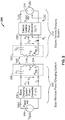
- FIG. 2 is a schematic diagram of exemplary core components of the wireless power transfer system 100 of FIG. 1 .
- the wireless power transfer system 200 may include a base system transmit circuit 206 including a base system induction coil 204 having an inductance L 1 .
- the wireless power transfer system 200 further includes an electric vehicle receive circuit 222 including an electric vehicle induction coil 216 having an inductance L 2 .
- Examples described herein may use capacitively loaded wire loops (i.e., multi-turn coils) forming a resonant structure that is capable of efficiently coupling energy from a primary structure (transmitter) to a secondary structure (receiver) via a magnetic or electromagnetic near field if both primary and secondary are tuned to a common resonant frequency.
- the coils may be used for the electric vehicle induction coil 216 and the base system induction coil 204.
- Using resonant structures for coupling energy may be referred to "magnetic coupled resonance,” “electromagnetic coupled resonance,” and/or “resonant induction.”
- the operation of the wireless power transfer system 200 will be described based on power transfer from a base wireless power charging system 202 to an electric vehicle 112, but is not limited thereto.
- the electric vehicle 112 may transfer power to the base wireless charging system 102a.
- a power supply 208 (e.g., AC or DC) supplies power P SDC to the base wireless power charging system 202 to transfer energy to an electric vehicle 112.
- the base wireless power charging system 202 includes a base charging system power converter 236.
- the base charging system power converter 236 may include circuitry such as an AC/DC converter configured to convert power from standard mains AC to DC power at a suitable voltage level, and a DC/low frequency (LF) converter configured to convert DC power to power at an operating frequency suitable for wireless high power transfer.
- the base charging system power converter 236 supplies power P 1 to the base system transmit circuit 206 including the capacitor C 1 in series with the base system induction coil 204 to emit an electromagnetic field at a desired frequency.
- the capacitor C 1 may be provided to form a resonant circuit with the base system induction coil 204 that resonates at a desired frequency.
- the base system induction coil 204 receives the power P 1 and wirelessly transmits power at a level sufficient to charge or power the electric vehicle 112.
- the power level provided wirelessly by the base system induction coil 204 may be on the order of kilowatts (kW) (e.g., anywhere from 1 kW to 110 kW or higher or lower).
- the base system transmit circuit 206 including the base system induction coil 204 and electric vehicle receive circuit 222 including the electric vehicle induction coil 216 may be tuned to substantially the same frequencies and may be positioned within the near-field of an electromagnetic field transmitted by one of the base system induction coil 204 and the electric vehicle induction coil 116. In this case, the base system induction coil 204 and electric vehicle induction coil 116 may become coupled to one another such that power may be transferred to the electric vehicle receive circuit 222 including capacitor C 2 and electric vehicle induction coil 116.
- the capacitor C 2 may be provided to form a resonant circuit with the electric vehicle induction coil 216 that resonates at a desired frequency.
- Element k(d) represents the mutual coupling coefficient resulting at coil separation.
- Equivalent resistances R eq,1 and R eq,2 represent the losses that may be inherent to the induction coils 204 and 216 and the anti-reactance capacitors C 1 and C 2 .
- the electric vehicle receive circuit 222 including the electric vehicle induction coil 316 and capacitor C 2 receives power P 2 and provides the power P 2 to an electric vehicle power converter 238 of an electric vehicle charging system 214.
- the electric vehicle power converter 238 may include, among other things, a LF/DC converter configured to convert power at an operating frequency back to DC power at a voltage level matched to the voltage level of an electric vehicle battery unit 218.
- the electric vehicle power converter 238 may provide the converted power P LDC to charge the electric vehicle battery unit 218.
- the power supply 208, base charging system power converter 236, and base system induction coil 204 may be stationary and located at a variety of locations as discussed above.
- the battery unit 218, electric vehicle power converter 238, and electric vehicle induction coil 216 may be included in an electric vehicle charging system 214 that is part of electric vehicle 112 or part of the battery pack (not shown).
- the electric vehicle charging system 214 may also be configured to provide power wirelessly through the electric vehicle induction coil 216 to the base wireless power charging system 202 to feed power back to the grid.
- Each of the electric vehicle induction coil 216 and the base system induction coil 204 may act as transmit or receive induction coils based on the mode of operation.
- the wireless power transfer system 200 may include a load disconnect unit (LDU) to safely disconnect the electric vehicle battery unit 218 or the power supply 208 from the wireless power transfer system 200.
- LDU load disconnect unit
- the LDU may be triggered to disconnect the load from the wireless power transfer system 200.
- the LDU may be provided in addition to a battery management system for managing charging to a battery, or it may be part of the battery management system.
- the electric vehicle charging system 214 may include switching circuitry (not shown) for selectively connecting and disconnecting the electric vehicle induction coil 216 to the electric vehicle power converter 238. Disconnecting the electric vehicle induction coil 216 may suspend charging and also may adjust the "load" as “seen” by the base wireless charging system 102a (acting as a transmitter), which may be used to "cloak” the electric vehicle charging system 114 (acting as the receiver) from the base wireless charging system 102a. The load changes may be detected if the transmitter includes the load sensing circuit. Accordingly, the transmitter, such as a base wireless charging system 202, may have a mechanism for determining when receivers, such as an electric vehicle charging system 114, are present in the near-field of the base system induction coil 204.
- the base system induction coil 204 and electric vehicle induction coil 116 are configured according to a mutual resonant relationship such that when the resonant frequency of the electric vehicle induction coil 116 and the resonant frequency of the base system induction coil 204 are very close or substantially the same. Transmission losses between the base wireless power charging system 202 and electric vehicle charging system 214 are minimal when the electric vehicle induction coil 216 is located in the near-field of the base system induction coil 204.
- an efficient energy transfer occurs by coupling a large portion of the energy in the near field of a transmitting induction coil to a receiving induction coil rather than propagating most of the energy in an electromagnetic wave to the far-field.
- a coupling mode may be established between the transmit induction coil and the receive induction coil.
- the area around the induction coils where this near field coupling may occur is referred to herein as a near field coupling mode region.
- the base charging system power converter 236 and the electric vehicle power converter 238 may both include an oscillator, a driver circuit such as a power amplifier, a filter, and a matching circuit for efficient coupling with the wireless power induction coil.
- the oscillator may be configured to generate a desired frequency, which may be adjusted in response to an adjustment signal.
- the oscillator signal may be amplified by a power amplifier with an amplification amount responsive to control signals.
- the filter and matching circuit may be included to filter out harmonics or other unwanted frequencies and match the impedance of the power conversion module to the wireless power induction coil.
- the power converters 236 and 238 may also include a rectifier and switching circuitry to generate a suitable power output to charge the battery.
- the electric vehicle induction coil 216 and base system induction coil 204 as described throughout the disclosed examples may be referred to or configured as "loop" antennas, and more specifically, multi-turn loop antennas.
- the induction coils 204 and 216 may also be referred to herein or be configured as “magnetic” antennas.
- the term “coil” generally refers to a component that may wirelessly output or receive energy four coupling to another "coil.”
- the coil may also be referred to as an "antenna" of a type that is configured to wirelessly output or receive power.
- coils 204 and 216 are examples of "power transfer components" of a type that are configured to wirelessly output, wirelessly receive, and/or wirelessly relay power.
- Loop antennas may be configured to include an air core or a physical core such as a ferrite core.
- An air core loop antenna may allow the placement of other components within the core area.
- Physical core antennas including ferromagnetic or ferromagnetic materials may allow development of a stronger electromagnetic field and improved coupling.
- Transfer of energy occurs by coupling energy from the near field of the transmitting induction coil to the receiving induction coil residing within a region (e.g., within a predetermined frequency range of the resonant frequency, or within a predetermined distance of the near-field region) where this near field is established rather than propagating the energy from the transmitting induction coil into free space.
- a resonant frequency may be based on the inductance and capacitance of a transmit circuit including an induction coil (e.g., the base system induction coil 204) as described above.
- inductance may generally be the inductance of the induction coil
- capacitance may be added to the induction coil to create a resonant structure at a desired resonant frequency.
- a capacitor may be added in series with the induction coil to create a resonant circuit (e.g., the base system transmit circuit 206) that generates an electromagnetic field.
- the value of capacitance needed to induce resonance may decrease as the diameter or inductance of the coil increases.
- Inductance may also depend on a number of turns of an induction coil.
- the efficient energy transfer area of the near field may increase.
- Other resonant circuits are possible.
- a capacitor may be placed in parallel between the two terminals of the induction coil (e.g., a parallel resonant circuit).
- an induction coil may be designed to have a high quality (Q) factor to improve the resonance of the induction coil.
- the Q factor may be 300 or greater.
- the near field may correspond to a region around the induction coil in which electromagnetic fields exist but may not propagate or radiate away from the induction coil.
- Near-field coupling-mode regions may correspond to a volume that is near the physical volume of the induction coil, typically within a small fraction of the wavelength.
- electromagnetic induction coils such as single and multi turn loop antennas, are used for both transmitting and receiving since magnetic near field amplitudes in practical examples tend to be higher for magnetic type coils in comparison to the electric near fields of an electric type antenna (e.g., a small dipole). This allows for potentially higher coupling between the pair.
- "electric" antennas e.g., dipoles and monopoles
- a combination of magnetic and electric antennas may be used.
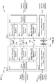
- FIG. 3 is another functional block diagram showing exemplary core and ancillary components of the wireless power transfer system 300 of FIG. 1 .
- the wireless power transfer system 300 illustrates a communication link 376, a guidance link 366, and alignment systems 352, 354 for the base system induction coil 304 and electric vehicle induction coil 316.
- a base charging system power interface 354 may be configured to provide power to a charging system power converter 336 from a power source, such as an AC or DC power supply 126.
- the base charging system power converter 336 may receive AC or DC power from the base charging system power interface 354 to excite the base system induction coil 304 at or near its resonant frequency.
- the electric vehicle induction coil 316 when in the near field coupling-mode region, may receive energy from the near field coupling mode region to oscillate at or near the resonant frequency.
- the electric vehicle power converter 338 converts the oscillating signal from the electric vehicle induction coil 316 to a power signal suitable for charging a battery via the electric vehicle power interface.
- the base wireless charging system 302 includes a base charging system controller 342 and the electric vehicle charging system 314 includes an electric vehicle controller 344.
- the base charging system controller 342 may include a base charging system communication interface 162 to other systems (not shown) such as, for example, a computer, and a power distribution center, or a smart power grid.
- the electric vehicle controller 344 may include an electric vehicle communication interface to other systems (not shown) such as, for example, an on-board computer on the vehicle, other battery charging controller, other electronic systems within the vehicles, and remote electronic systems.
- the base charging system controller 342 and electric vehicle controller 344 may include subsystems or modules for specific application with separate communication channels. These communications channels may be separate physical channels or separate logical channels.
- a base charging alignment system 352 may communicate with an electric vehicle alignment system 354 through a communication link 376 to provide a feedback mechanism for more closely aligning the base system induction coil 304 and electric vehicle induction coil 316, either autonomously or with operator assistance.
- a base charging guidance system 362 may communicate with an electric vehicle guidance system 364 through a guidance link to provide a feedback mechanism to guide an operator in aligning the base system induction coil 304 and electric vehicle induction coil 316.
- each communication channel may be separate physical communication channels such as, for example, Bluetooth, zigbee, cellular, etc.
- Electric vehicle controller 344 may also include a battery management system (BMS) (not shown) that manages charge and discharge of the electric vehicle principal battery, a parking assistance system based on microwave or ultrasonic radar principles, a brake system configured to perform a semi-automatic parking operation, and a steering wheel servo system configured to assist with a largely automated parking 'park by wire' that may provide higher parking accuracy, thus reducing the need for mechanical horizontal induction coil alignment in any of the base wireless charging system 102a and the electric vehicle charging system 114. Further, electric vehicle controller 344 may be configured to communicate with electronics of the electric vehicle 112.
- BMS battery management system
- electric vehicle controller 344 may be configured to communicate with electronics of the electric vehicle 112.
- electric vehicle controller 344 may be configured to communicate with visual output devices (e.g., a dashboard display), acoustic/audio output devices (e.g., buzzer, speakers), mechanical input devices (e.g., keyboard, touch screen, and pointing devices such as joystick, trackball, etc.), and audio input devices (e.g., microphone with electronic voice recognition).
- visual output devices e.g., a dashboard display
- acoustic/audio output devices e.g., buzzer, speakers
- mechanical input devices e.g., keyboard, touch screen, and pointing devices such as joystick, trackball, etc.
- audio input devices e.g., microphone with electronic voice recognition
- the wireless power transfer system 300 may include detection and sensor systems.
- the wireless power transfer system 300 may include sensors for use with systems to properly guide the driver or the vehicle to the charging spot, sensors to mutually align the induction coils with the required separation/coupling, sensors to detect objects that may obstruct the electric vehicle induction coil 316 from moving to a particular height and/or position to achieve coupling, and safety sensors for use with systems to perform a reliable, damage free, and safe operation of the system.
- a safety sensor may include a sensor for detection of presence of animals or children approaching the wireless power induction coils 104a, 116 beyond a safety radius, detection of metal objects near the base system induction coil 304 that may be heated up (induction heating), detection of hazardous events such as incandescent objects on the base system induction coil 304, and temperature monitoring of the base wireless power charging system 302 and electric vehicle charging system 314 components.
- the wireless power transfer system 300 may also support plug-in charging via a wired connection.
- a wired charge port may integrate the outputs of the two different chargers prior to transferring power to or from the electric vehicle 112.
- Switching circuits may provide the functionality as needed to support both wireless charging and charging via a wired charge port.
- the wireless power transfer system 300 may use both in-band signaling and an RF data modem (e.g., Ethernet over radio in an unlicensed band).
- the out-of-band communication may provide sufficient bandwidth for the allocation of value-add services to the vehicle user/owner.
- a low depth amplitude or phase modulation of the wireless power carrier may serve as an in-band signaling system with minimal interference.
- the wireless power induction coils 304 and 316 may also be configured to act as wireless communication transmitters.
- the base wireless power charging system 302 may include a controller (not shown) for enabling keying type protocol on the wireless power path. By keying the transmit power level (amplitude shift keying) at predefined intervals with a predefined protocol, the receiver may detect a serial communication from the transmitter.
- the base charging system power converter 336 may include a load sensing circuit (not shown) for detecting the presence or absence of active electric vehicle receivers in the vicinity of the near field generated by the base system induction coil 304.
- a load sensing circuit monitors the current flowing to the power amplifier, which is affected by the presence or absence of active receivers in the vicinity of the near field generated by base system induction coil 104a. Detection of changes to the loading on the power amplifier may be monitored by the base charging system controller 342 for use in determining whether to enable the oscillator for transmitting energy, to communicate with an active receiver, or a combination thereof.
- some examples may be configured to transfer power at a frequency in the range from 10-60 kHz. This low frequency coupling may allow highly efficient power conversion that may be achieved using solid state devices. In addition, there may be less coexistence issues with radio systems compared to other bands.
- FIG. 4 is a functional block diagram showing a replaceable contactless battery disposed in an electric vehicle 412.
- the low battery position may be useful for an electric vehicle battery unit that integrates a wireless power interface (e.g., a charger-to-battery cordless interface 426) and that may receive power from a charger (not shown) embedded in the ground.
- the electric vehicle battery unit may be a rechargeable battery unit, and may be accommodated in a battery compartment 424.
- the electric vehicle battery unit also provides a wireless power interface 426, which may integrate the entire electric vehicle wireless power subsystem including a resonant induction coil, power conversion circuitry, and other control and communications functions as needed for efficient and safe wireless energy transfer between a ground-based wireless charging unit and the electric vehicle battery unit.
- a wireless power interface 426 may integrate the entire electric vehicle wireless power subsystem including a resonant induction coil, power conversion circuitry, and other control and communications functions as needed for efficient and safe wireless energy transfer between a ground-based wireless charging unit and the electric vehicle battery unit.
- the electric vehicle battery unit 422 may also include a battery-to-EV cordless interface 422, and a charger-to-battery cordless interface 426 that provides contactless power and communication between the electric vehicle 412 and a base wireless charging system 102a as shown in FIG. 1 .
- the base system induction coil 104a and the electric vehicle induction coil 116 may be in a fixed position and the induction coils are brought within a near-field coupling region by overall placement of the electric vehicle induction coil 116 relative to the base wireless charging system 102a.
- the distance between the base system induction coil 104a and the electric vehicle induction coil 116 may need to be reduced to improve coupling.
- the base system induction coil 104a and/or the electric vehicle induction coil 116 may be deployable and/or moveable to bring them into better alignment.
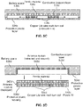
- FIGs. 5A, 5B , 5C, and 5D are diagrams of exemplary configurations for the placement of an induction coil and ferrite material relative to a battery.
- FIG. 5A shows a fully ferrite embedded induction coil 536a.
- the wireless power induction coil may include a ferrite material 538a and a coil 536a wound about the ferrite material 538a.
- the coil 536a itself may be made of stranded Litz wire.
- a conductive shield 532a may be provided to protect passengers of the vehicle from excessive EMF transmission. Conductive shielding may be particularly useful in vehicles made of plastic or composites.
- FIG. 5B shows an optimally dimensioned ferrite plate (i.e., ferrite backing) to enhance coupling and to reduce eddy currents (heat dissipation) in the conductive shield 532b.
- the coil 536b may be fully embedded in a non-conducting non-magnetic (e.g., plastic) material.
- the coil 536b may be embedded in a protective housing 534b. There may be a separation between the coil 536b and the ferrite material 538b as the result of a trade-off between magnetic coupling and ferrite hysteresis losses.
- FIG. 5C illustrates another example where the coil 536c (e.g., a copper Litz wire multi-turn coil) may be movable in a lateral ("X") direction.
- FIG. 5D illustrates another example where the induction coil module is deployed in a downward direction.
- the battery unit includes one of a deployable and non-deployable electric vehicle induction coil module 540d as part of the wireless power interface.
- a conductive shield 532d e.g., a copper sheet
- a non-conductive (e.g., plastic) protective layer 533d may be used to protect the conductive shield 532d, the coil 536d, and the ferrite material 5d38 from environmental impacts (e.g., mechanical damage, oxidization, etc.).
- the coil 536d may be movable in lateral X and/or Y directions.
- FIG. 5D illustrates an example wherein the electric vehicle induction coil module 540d is deployed in a downward Z direction relative to a battery unit body.
- this deployable electric vehicle induction coil module 542b is similar to that of FIG. 5B except there is no conductive shielding at the electric vehicle induction coil module 542d.
- the conductive shield 532d stays with the battery unit body.
- the protective layer 533d e.g., plastic layer
- the physical separation of the electric vehicle induction coil module 542 from the battery unit body may have a positive effect on the induction coil's performance.
- the electric vehicle induction coil module 542d that is deployed may contain only the coil 536d (e.g., Litz wire) and ferrite material 538d. Ferrite backing may be provided to enhance coupling and to prevent from excessive eddy current losses in a vehicle's underbody or in the conductive shield 532d.
- the electric vehicle induction coil module 542d may include a flexible wire connection to power conversion electronics and sensor electronics. This wire bundle may be integrated into the mechanical gear for deploying the electric vehicle induction coil module 542d.
- the charging systems described above may be used in a variety of locations for charging an electric vehicle 112, or transferring power back to a power grid.
- the transfer of power may occur in a parking lot environment.
- a "parking area” may also be referred to herein as a "parking space.”
- an electric vehicle 112 may be aligned along an X direction and a Y direction to enable an electric vehicle induction coil 116 within the electric vehicle 112 to be adequately aligned with a base wireless charging system 102a within an associated parking area.
- the disclosed examples are applicable to parking lots having one or more parking spaces or parking areas, wherein at least one parking space within a parking lot may comprise a base wireless charging system 102a.
- Guidance systems may be used to assist a vehicle operator in positioning an electric vehicle 112 in a parking area to align an electric vehicle induction coil 116 within the electric vehicle 112 with a base wireless charging system 102a.
- Guidance systems may include electronic based approaches (e.g., radio positioning, direction finding principles, and/or optical, quasi-optical and/or ultrasonic sensing methods) or mechanical-based approaches (e.g., vehicle wheel guides, tracks or stops), or any combination thereof, for assisting an electric vehicle operator in positioning an electric vehicle 112 to enable an induction coil 116 within the electric vehicle 112 to be adequately aligned with a charging induction coil within a charging base (e.g., base wireless charging system 102a).
- a charging base e.g., base wireless charging system 102a
- the electric vehicle charging system 114 may be placed on the underside of the electric vehicle 112 for transmitting and receiving power from a base wireless charging system 102a.
- an electric vehicle induction coil 116 may be integrated into the vehicles underbody preferably near a center position providing maximum safety distance in regards to EM exposure and permitting forward and reverse parking of the electric vehicle.
- FIG. 6 is a chart of a frequency spectrum showing exemplary frequencies that may be used for wireless charging an electric vehicle.
- potential frequency ranges for wireless high power transfer to electric vehicles may include: VLF in a 3 kHz to 30 kHz band, lower LF in a 30 kHz to 150 kHz band (for ISM-like applications) with some exclusions, HF 6.78 MHz (ITU-R ISM-Band 6.765 - 6.795 MHz), HF 13.56 MHz (ITU-R ISM-Band 13.553 - 13.567), and HF 27.12 MHz (ITU-R ISM-Band 26.957 - 27.283).
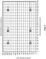
- FIG. 7 is a chart showing exemplary frequencies and transmission distances that may be useful in wireless charging electric vehicles.
- Some example transmission distances that may be useful for electric vehicle wireless charging are about 30 mm, about 75 mm, and about 150 mm.
- Some exemplary frequencies may be about 27 kHz in the VLF band and about 135 kHz in the LF band.
- Living beings e.g., humans or animals
- Existing systems utilize vehicle immobilization upon detection of such a living being below the vehicle to avoid running over or otherwise impacting the living being upon movement of the vehicle.
- Other existing systems seek to repel living beings from entering regions in which they can be potentially exposed to hazardous conditions (e.g., ultrasonic systems configured to repel martens from the vehicle engine).
- the exclusion zone can be defined as a volume from which living beings are desired to be excluded.
- the exclusion zone can be the volume in which electromagnetic field (EMF) exposure can exceed predetermined limits, or can be the complete volume underneath the vehicle (e.g., region between the vehicle and the ground bounded by the vehicle outline).
- EMF electromagnetic field
- the wireless charging system can pause power transfer for a predetermined period of time. During this pause period, the detection system can continue to monitor the exclusion zone. Power transfer can resume (e.g., automatically without user intervention), if there is no moving object detected in the exclusion zone for the duration of the pause period.
- the wireless charging system can comprise a controller (e.g., processor or other control structure as described above) configured to receive signals from the detection system indicative of whether there is a moving object in the exclusion zone or not, and configured to transmit appropriate control signals to other portions of the wireless charging system.
- FIGs. 8A and 8B schematically illustrate example detection apparatus 800 configured to monitor at least a portion of the exclusion zone 802 in accordance with certain embodiments described herein.
- the detection apparatus 800 is positioned to monitor at least a portion of the exclusion zone 802 underneath the vehicle 804 (e.g., in proximity to a vehicle charging pad 806) and to detect existence of a moving object (e.g., living being) within the exclusion zone 802.
- the vehicle charging pad 806 can be on a first portion of the vehicle (e.g., on the vehicle's underbody structure 808) and the detection apparatus 800 is on a surface of a second portion underside of the vehicle.
- the portion of the exclusion zone 802 being monitored by the detection apparatus 800 is also in proximity to the base charging pad 810.
- the detection apparatus 800 comprises at least one antenna assembly 812 configured to transmit radiation and to receive radiation reflected from material within the exclusion zone 802.
- the at least one antenna assembly 812 can comprise one or more antennas configured to transmit electromagnetic radiation (e.g., energy waves) and one or more antennas configured to receive at least a portion of the emitted radiation after it has reflected from material within the exclusion zone.
- the one or more antennas configured to transmit radiation can be the same one or more antennas configured to receive the reflected radiation, or the one or more antennas configured to transmit radiation can be separate and spaced from the one or more antennas configured to receive the reflected radiation.
- the at least one antenna assembly 812 of FIGs. 8A and 8B is on an underbody structure 808 of the electric vehicle 804.
- multiple antenna assemblies can be mounted at the vehicle bottom (e.g., adjacent to the vehicle-side power charging pad 806). This location can be advantageous with regard to discriminating return signals from moving objects outside the exclusion zone 802.
- the two antenna assemblies shown in FIG. 8A (labeled 812a and 812b) can be configured to detect moving objects or living beings in two corresponding regions 814a, 814b(e.g., surveillance spaces; denoted by dashed lines) between the vehicle underbody structure 806 and the ground 816 and extending at least partially over the base charging pad 810. While FIG.
- regions 814a, 814b can be overlapping in other configurations, such that there is a region in which both antenna assemblies 812a, 812b can detect the moving object or living being.
- other configurations can utilize more than two antenna assemblies 812 and more than two regions 814 (e.g., surveillance spaces), which may at least partially overlap one another.
- the detection system 800 can utilize microwave Doppler radar to detect motion of the object or living being.
- Microwave Doppler radar systems transmit microwave electromagnetic radiation (e.g., energy waves) towards a target region and receive return signals (e.g., energy waves) reflected from objects within the target region. The frequency of these return signals is indicative of a velocity of the object (relative to the detector) from which the return signal is reflected.
- An example suitable operating frequency for such microwave Doppler radar for detecting objects or living beings within the exclusion zone can be 24 GHz/K-Band inside the internationally harmonized band (EU, UK, NA). Other operating frequencies are also compatible with certain embodiments described herein.
- the detection system 800 can comprise at least one antenna assembly 812 configured to irradiate the portion of the exclusion zone 802 with microwave electromagnetic radiation, and at least one antenna assembly 812 configured to receive return signals from the moving objects or living beings within the exclusion zone.
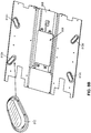
- antenna assemblies 812 labeleled as 812a, 812b, 812c, 812d; and which can be referred to as "radar modules" can be positioned in a generally rectangular pattern on or integral with a vehicle shield of the electric vehicle 804, with the vehicle charging pad 806 positioned between the antenna assemblies 812.
- Each antenna assembly 812 can have a housing and an integrated microwave front end and a Doppler detector unit.
- FIG. 9 schematically illustrates two example potential contributions to false detection events for a microwave Doppler radar detection system.
- "Nadir" pointing radar detection systems mounted at the bottom of a vehicle may transmit microwave radiation towards the ground (schematically illustrated by the nearly vertical solid arrow of FIG. 9 ) and may receive strong return signals (e.g., echoes) from the ground or from any other microwave-reflective object on the ground (schematically illustrated by the nearly vertical dashed arrow of FIG. 9 ).
- the vehicle moves slightly up and down (e.g., due to bouncing of the vehicle suspension system, persons entering or leaving the vehicle, wind forces acting on the vehicle)(schematically illustrated by the doubleheaded arrow in FIG. 9 )
- the received return signals resulting from reflections of the microwave radiation from the ground can be mistaken as return signals reflected from a moving object or living being within the exclusion zone, resulting in a false detection event.
- such "nadir" pointing radar detection systems may also transmit microwave radiation generally parallel to the ground (schematically illustrated by the nearly horizontal solid arrow of FIG. 9 ) and may receive strong return signals (e.g., echoes) from microwave-reflective objects outside the exclusion zone (schematically illustrated by the nearly horizontal dashed arrow of FIG. 9 ). These received return signals resulting from reflections from objects or living beings outside the exclusion zone can be mistaken as return signals reflected from a moving object or living being within the exclusion zone, resulting in a false detection event.
- strong return signals e.g., echoes
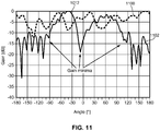
- FIG. 10 schematically illustrates a planar cross-section of an example radiation pattern 1000 according to the invention.
- the radiation pattern 1000 of FIG. 10 is a planar cross-section of an example radiation pattern 1000 according to the invention.
- the radiation pattern 1000 of FIG. 10 is a planar cross-section of an example radiation pattern 1000 according to the invention.
- the at least one antenna assembly 812 is configured to generate radiation and to receive radiation reflected from material within the exclusion zone 802.
- the radiation pattern 1000 for at least one of the transmitted radiation and the received radiation has a maximum gain and can have a gain along a line 1004 perpendicular to the surface 1002 less than half of the maximum gain on a linear scale.
- the planar cross-section of FIG. 10 is in a plane perpendicular to the surface 1002.
- the radiation pattern 1000, in the plane perpendicular to the surface 1002 has a first gain 1006 along a first line 1004 perpendicular to the surface (e.g., along a vertical axis, shown schematically in FIG. 10 by a downward-pointing vertical arrow), a second gain 1008 along a second line 1010 parallel to the surface 1002 (e.g., along a horizontal axis, shown schematically in FIG. 10 by a rightward-pointing horizontal arrow), and a maximum gain 1012 along a third line 1014 between the first line 1004 and the second line 1010 (e.g., along a line 1014 shown schematically in FIG. 10 by a dashed line).
- the first gain 1006 is less than half the maximum gain 1012 and the second gain 1008 is less than half the maximum gain 1012 on a linear scale.
- the radiation pattern 1000 shown in FIG. 10 can be described as being generally omnidirectional in azimuth (e.g., generally rotationally symmetric about the vertical axis) and as having a lobe in elevation along the third line 1014 (e.g., at an angle relative to the horizontal axis).
- the radiation pattern 1000 has gain minima at elevation of zero degrees (e.g., along the second line 1010 which is along the horizontal axis) and at elevation of 90 degrees (e.g., along the first line 1004 which is along the vertical axis).
- the third line 1014 can be at an elevation angle (e.g., relative to the horizontal axis 1010) of about 30 degrees, about 35 degrees, about 40 degrees, about 45 degrees, about 50 degrees, about 55 degrees, about 60 degrees, between 30 and 35 degrees, between 35 and 40 degrees, between 40 and 45 degrees, between 45 and 50 degrees, between 50 and 55 degrees, or between 55 and 60 degrees.
- the radiation pattern 1000 can be generally rotationally symmetric about the first line 1004 (e.g., about the vertical axis).
- the at least one antenna assembly 812 can be positioned along the first line 1004 (e.g., along the vertical axis).
- the maximum gain 1012 on a linear scale can be greater than the first gain 1006 by a factor of 2, 3, 4, 5, 6, 7, 8, 9, 10, 20, 50, or more, greater than the second gain 1008 by a factor of 2, 3, 4, 5, 6, 7, 8, 9, 10, 20, 50, or more, or both.
- the first gain 1006 can be less than the maximum gain 1012 by at least 10 dB on a logarithmic scale and the second gain 1008 can be less than the maximum gain 1012 by at least 10 dB on a logarithmic scale.
- the first gain 1006 can be the same or different from the second gain 1008.
- the gain of the lobe portion on a first side of the vertical axis can be the same or different from the gain of the lobe portion on a second side of the vertical axis (e.g., a second lobe portion 1016b between the vertical axis and the portion of the horizontal axis on the left-side of the vertical axis of FIG. 10 ). If the gains of these two lobe portions 1016a, 1016b are different from one another, the greater gain of the two can be considered the maximum gain 1012.
- multiple antenna assemblies 812 can be used that are optimally spaced from one another to receive return signals from corresponding portions of the exclusion zone 802 such that substantially all of the exclusion zone 802 can be monitored by the detection system 800.
- the operating frequency and transmit level of each antenna assembly 812 can be controlled to prevent false detection events due to mutual interference and receiver overloading (e.g., in case of temperature drift, aging, or other conditions).
- frequency can be controlled by means of changing local oscillator supply voltage, and the transmit level of the antenna assemblies 812 can be reduced (e.g., attenuated by 3 to 10 dB) by placing absorber foam material on each antenna assembly 812.
- FIG. 11 is a plot of the measured azimuthal pattern 1100 and the measured elevation pattern 1102 for an example radiation pattern 1000 in accordance with certain embodiments described herein.
- the radiation pattern 1000 of FIG. 11 has been measured on an arrangement of two " ⁇ /4" monopole rod antennas 812 (e.g., having a length approximately equal to one-fourth of the wavelength of the emitted radiation) which can be vertically oriented relative to the surface 1002 of the vehicle's underbody 808.
- FIG. 11 shows the variation of the gain as a function of angle (e.g., relative to a reference direction within a plane parallel to the surface 1002 of the vehicle's underbody 808) about the vertical axis (e.g., the direction perpendicular to the surface 1002) to be within a range of about -12 dB.
- a radiation pattern 1000 is an example of a radiation pattern that is generally omnidirectional in azimuth.
- the elevation pattern 1102 of FIG. 11 shows the variation of the gain as a function of angle from the vertical axis (e.g., the direction perpendicular to the surface 1002) to have gain minima at about zero degrees and at about ⁇ 90 degrees.
- the radiation pattern 1000 has a lobe with a maximum gain 1012 at an elevation angle of about 40-70 degrees.
- the negative values of angle correspond to a first lobe portion 1016a on a first side of the vertical axis and the positive values of angle correspond to a second lobe portion 1016b on a second side (opposite to the first side) of the vertical axis.
- FIG. 12 schematically illustrates an example antenna assembly 812.
- the antenna assembly 812 of FIG. 12 comprises at least one patch antenna 1200 (e.g., a patch array) mounted on a substrate 1202.
- the at least one patch antenna 1200 generates a radiation pattern 1000 having a lobe pointing in the downward vertical direction (e.g., towards the ground 816).
- the antenna assembly 812 of FIG. 12 further comprises at least one metal plate 1204 positioned below the at least one patch antenna 1200 by a distance (schematically illustrated in FIG. 12 by the double-sided arrow). For a 24-GHz system, the distance can be between 5 millimeters and 10 millimeters below the at least one patch antenna 1200.
- the metal plate 1204 is configured to alter the radiation pattern 1000 such that the gain in the downward vertical direction is reduced, and to produce lobes at a predetermined elevation angle between the horizontal axis and the vertical axis.
- the metal plate 1204 can be acoustically damped (e.g., using foam material placed between the substrate 1202 and the metal plate 1204) such that the metal plate 1204 does not substantially vibrate or oscillate in position relative to the substrate 1202.
- FIG. 13 is a flow diagram of an example method 1300 of controlling a wireless charging system of an electric vehicle.
- the method 1300 comprises transmitting energy waves in a region below an underside surface of the electric vehicle in an operational block 1302.
- the method 1300 further comprises receiving energy waves reflected from material within the region in an operational block 1304.
- the method 1300 further comprises analyzing the received energy waves to determine whether the received energy waves are indicative of a living being within the region in operational blocks 1306 and 1308.
- the transmitted energy waves can be in a pattern having a maximum gain and having a first gain along a line perpendicular to the surface less than half of the maximum gain.
- the received energy waves can be in a pattern having a maximum gain and having a first gain along a line perpendicular to the surface less than half of the maximum gain.
- the method 1300 of FIG. 13 further comprises, upon determining that the received energy waves are indicative of a moving object (e.g., living being) within the region in an operational block 1308, pausing power transfer by the wireless charging system in an operational block 1310.
- the method 1300 further comprises continuing said transmitting, said receiving, and said analyzing while power transfer is paused (e.g., for the duration of the paused period).
- the method 1300 further comprises, upon determining that the received energy waves are not indicative of a moving object (e.g., living being) within the region in the operational block 1308 while power transfer is paused, initiating power transfer by the wireless charging system in an operational block 1312.
- the wireless power charging system can comprise means for wirelessly transferring power to the electric vehicle 804 (e.g., a base charging pad 810, a vehicle charging pad 806, and other structure utilized in transferring power to the electric vehicle 804 as described herein), at least one means for receiving electromagnetic radiation, and at least one means for transmitting electromagnetic radiation.
- At least one of the received electromagnetic radiation and the transmitted electromagnetic radiation has a radiation pattern 1000.
- the radiation pattern 1000 can have a maximum gain 1012 and can have a first gain 1006 along a first line 1004 perpendicular to the surface 1002 less than half of the maximum gain 1012 on a linear scale.
- the at least one receiving means can comprise at least one microwave radar sensor or at least one antenna assembly 812.
- the at least one transmitting means can comprise at least one antenna assembly 812 (e.g., the same at least one antenna assembly of the at least one receiving means).
- the wireless power charging system can further comprise means for controlling the transferring means in response to signals from the at least one receiving means.
- the controlling means can comprise a processor configured to receive signals from the at least one receiving means and to transmit control signals to the transferring means.
- any suitable means capable of performing the operations such as various hardware and/or software component(s), circuits, and/or module(s).
- any operations illustrated in the Figures may be performed by corresponding functional means capable of performing the operations.
- Information and signals may be represented using any of a variety of different technologies and techniques.
- data, instructions, commands, information, signals, bits, symbols, and chips that may be referenced throughout the above description may be represented by voltages, currents, electromagnetic waves, magnetic fields or particles, optical fields or particles, or any combination thereof.
- DSP Digital Signal Processor
- ASIC Application Specific Integrated Circuit
- FPGA Field Programmable Gate Array
- a general purpose processor may be a microprocessor, but in the alternative, the processor may be any conventional processor, controller, microcontroller, or state machine.
- a processor may also be implemented as a combination of computing devices, e.g., a combination of a DSP and a microprocessor, a plurality of microprocessors, one or more microprocessors in conjunction with a DSP core, or any other such configuration.
- a software module may reside in Random Access Memory (RAM), flash memory, Read Only Memory (ROM), Electrically Programmable ROM (EPROM), Electrically Erasable Programmable ROM (EEPROM), registers, hard disk, a removable disk, a CD ROM, or any other form of storage medium known in the art.
- RAM Random Access Memory
- ROM Read Only Memory
- EPROM Electrically Programmable ROM
- EEPROM Electrically Erasable Programmable ROM
- registers hard disk, a removable disk, a CD ROM, or any other form of storage medium known in the art.
- a storage medium is coupled to the processor such that the processor can read information from, and write information to, the storage medium.
- the storage medium may be integral to the processor.
- Disk and disc includes compact disc (CD), laser disc, optical disc, digital versatile disc (DVD), floppy disk and blu ray disc where disks usually reproduce data magnetically, while discs reproduce data optically with lasers. Combinations of the above should also be included within the scope of computer readable media.
- the processor and the storage medium may reside in an ASIC.
- the ASIC may reside in a user terminal.
- the processor and the storage medium may reside as discrete components in a user terminal.
Landscapes
- Engineering & Computer Science (AREA)
- Power Engineering (AREA)
- Transportation (AREA)
- Mechanical Engineering (AREA)
- Computer Networks & Wireless Communication (AREA)
- Remote Sensing (AREA)
- Radar, Positioning & Navigation (AREA)
- Physics & Mathematics (AREA)
- General Physics & Mathematics (AREA)
- Electromagnetism (AREA)
- Electric Propulsion And Braking For Vehicles (AREA)
- Charge And Discharge Circuits For Batteries Or The Like (AREA)
- Current-Collector Devices For Electrically Propelled Vehicles (AREA)
- Radar Systems Or Details Thereof (AREA)
Applications Claiming Priority (3)
| Application Number | Priority Date | Filing Date | Title |
|---|---|---|---|
| US201361822114P | 2013-05-10 | 2013-05-10 | |
| US14/059,299 US9365126B2 (en) | 2013-05-10 | 2013-10-21 | System and method for detecting the presence of a moving object below a vehicle |
| PCT/US2014/035468 WO2014182471A2 (en) | 2013-05-10 | 2014-04-25 | System and method for detecting the presence of a moving object below a vehicle |
Publications (2)
| Publication Number | Publication Date |
|---|---|
| EP2994343A2 EP2994343A2 (en) | 2016-03-16 |
| EP2994343B1 true EP2994343B1 (en) | 2020-12-23 |
Family
ID=51864317
Family Applications (1)
| Application Number | Title | Priority Date | Filing Date |
|---|---|---|---|
| EP14727310.6A Active EP2994343B1 (en) | 2013-05-10 | 2014-04-25 | System and method for detecting the presence of a moving object below a vehicle |
Country Status (6)
| Country | Link |
|---|---|
| US (1) | US9365126B2 (ja) |
| EP (1) | EP2994343B1 (ja) |
| JP (1) | JP6469087B2 (ja) |
| KR (1) | KR102203600B1 (ja) |
| CN (1) | CN105163976B (ja) |
| WO (1) | WO2014182471A2 (ja) |
Families Citing this family (65)
| Publication number | Priority date | Publication date | Assignee | Title |
|---|---|---|---|---|
| DE102009033235A1 (de) * | 2009-07-14 | 2011-01-20 | Conductix-Wampfler Ag | Energieversorgungseinheit, Landfahrzeug, Austauschstation und Verfahren zum Austausch einer in einem Landfahrzeug enthaltenen Energieversorgungseinheit |
| KR101697418B1 (ko) | 2012-05-09 | 2017-01-17 | 도요타지도샤가부시키가이샤 | 차량 |
| US11616520B2 (en) | 2012-11-09 | 2023-03-28 | California Institute Of Technology | RF receiver |
| US11843260B2 (en) | 2012-11-09 | 2023-12-12 | California Institute Of Technology | Generator unit for wireless power transfer |
| CN104885333B (zh) * | 2012-11-09 | 2018-05-15 | 加州理工学院 | 智能rf透镜效应:高效、动态和移动无线功率传输 |
| US10093194B2 (en) | 2013-09-30 | 2018-10-09 | Elwha Llc | Communication and control system and method regarding electric vehicle for wireless electric vehicle electrical energy transfer |
| US20150094867A1 (en) | 2013-09-30 | 2015-04-02 | Elwha Llc | User interface to residence related information center associated with communication and control system and method for wireless electric vehicle electrical energy transfer |
| US9412515B2 (en) | 2013-09-30 | 2016-08-09 | Elwha, Llc | Communication and control regarding wireless electric vehicle electrical energy transfer |
| US9199548B2 (en) | 2013-09-30 | 2015-12-01 | Elwha Llc | Communication and control regarding electricity provider for wireless electric vehicle electrical energy transfer |
| CN105765821B (zh) * | 2013-11-22 | 2019-08-09 | 加州理工学院 | 用于无线电力输送的发生器单元 |
| JP5937631B2 (ja) | 2014-01-31 | 2016-06-22 | トヨタ自動車株式会社 | 非接触電力伝送システムおよび充電ステーション |
| US9952266B2 (en) * | 2014-02-14 | 2018-04-24 | Witricity Corporation | Object detection for wireless energy transfer systems |
| US20150336464A1 (en) * | 2014-05-23 | 2015-11-26 | Ford Global Technologies, Llc | Ultrasonic location for electric vehicle charging system |
| CN106663968B (zh) | 2014-08-19 | 2020-03-03 | 加州理工学院 | 用于无线功率传输的恢复单元和从rf波生成dc功率的方法 |
| DE102014217937A1 (de) * | 2014-09-08 | 2016-03-10 | Robert Bosch Gmbh | Verfahren und System zur Sicherung eines berührungslosen Lade-/Entladevorgangs eines batteriebetriebenen Objekts, insbesondere eines Elektrofahrzeugs |
| US10012725B2 (en) | 2014-12-19 | 2018-07-03 | Qualcomm Incorporated | Systems, methods, and apparatus for living object protection having extended functionality in wireless power transfer applications |
| GB2525471A (en) * | 2015-02-23 | 2015-10-28 | Daimler Ag | Wireless charging apparatus for an electric vehicle and method for operating the same |
| CN113904458A (zh) * | 2015-04-15 | 2022-01-07 | 无线先进车辆电气化有限公司 | 可移除式感应电力传输垫 |
| US10444337B2 (en) * | 2015-05-22 | 2019-10-15 | Witricity Corporation | Methods and apparatus utilizing time division access of multiple radar modules in living object detection for wireless power transfer applications |
| US9912187B2 (en) | 2015-09-01 | 2018-03-06 | Dell Products, Lp | Wireless power transmission antenna with thermally conductive magnetic shield and method therefor |
| US9876382B2 (en) | 2015-09-01 | 2018-01-23 | Dell Products, Lp | Peak power caching in a wireless power system |
| US9954388B2 (en) | 2015-09-01 | 2018-04-24 | Dell Products, Lp | Cover system for wireless power pad |
| US10148115B2 (en) * | 2015-09-01 | 2018-12-04 | Dell Products, Lp | Wireless charging pad with natural draft cooling and method therefor |
| US9954387B2 (en) | 2015-09-01 | 2018-04-24 | Dell Products, Lp | Wireless charging pad with interdependent temperature control and method therefor |
| US9973027B2 (en) | 2015-09-01 | 2018-05-15 | Dell Products, Lp | Wireless power charging device with rear side magneto isolation marking |
| US10532663B2 (en) | 2015-11-13 | 2020-01-14 | Nio Usa, Inc. | Electric vehicle overhead charging system and method of use |
| US10059213B2 (en) | 2015-11-13 | 2018-08-28 | Nio Usa, Inc. | Charging devices within wheel portions |
| US10336194B2 (en) * | 2015-11-13 | 2019-07-02 | Nio Usa, Inc. | Electric vehicle charging device alignment and method of use |
| US10189363B2 (en) | 2015-11-13 | 2019-01-29 | Nio Usa, Inc. | Electric vehicle roadway charging system and method of use |
| US10632852B2 (en) | 2015-11-13 | 2020-04-28 | Nio Usa, Inc. | Electric vehicle optical charging system and method of use |
| US20170136887A1 (en) * | 2015-11-13 | 2017-05-18 | NextEv USA, Inc. | Electric vehicle aerial vehicle charging system and method of use |
| US10093195B2 (en) | 2015-11-13 | 2018-10-09 | Nio Usa, Inc. | Integrated vehicle charging panel system and method of use |
| CN108700644A (zh) * | 2015-12-21 | 2018-10-23 | 皇家Kpn公司 | 用于与至少一个邻近设备通信的设备和方法 |
| US20170182903A1 (en) * | 2015-12-26 | 2017-06-29 | Intel Corporation | Technologies for wireless charging of electric vehicles |
| US10000134B2 (en) * | 2016-03-28 | 2018-06-19 | Denso International America, Inc. | Wireless charging system for charging vehicular battery |
| US10128698B2 (en) * | 2016-06-20 | 2018-11-13 | Hyundai America Technical Center, Inc | Device and method for detecting an object within a wireless charging region |
| US10239415B2 (en) * | 2016-06-24 | 2019-03-26 | Qualcomm Incorporated | Base side vehicle identification using vehicle controller switching frequency |
| US10399449B2 (en) * | 2016-08-08 | 2019-09-03 | Hyundai Motor Company | Wireless charging control apparatus and method for optimal charging by adjusting the inclination of the electric vehicle being charged |
| JP6460068B2 (ja) * | 2016-09-05 | 2019-01-30 | トヨタ自動車株式会社 | 車両 |
| CN107809142A (zh) * | 2016-09-09 | 2018-03-16 | 现代自动车株式会社 | 使用对象检测传感器的无线电力传输控制方法和设备 |
| US10361590B2 (en) | 2017-03-13 | 2019-07-23 | Dell Products, Lp | Wireless power system with device specific power configuration and method therefor |
| US10523037B2 (en) | 2017-03-13 | 2019-12-31 | Dell Products, Lp | Thermal management at a wireless power system |
| US10476307B2 (en) | 2017-03-13 | 2019-11-12 | Dell Products, Lp | Wireless power system with foreign object detection and method therefor |
| DE102017218226A1 (de) * | 2017-03-20 | 2018-09-20 | Fraunhofer-Gesellschaft zur Förderung der angewandten Forschung e.V. | Unterflur-Kontaktsystem |
| US10245966B2 (en) * | 2017-04-11 | 2019-04-02 | GM Global Technology Operations LLC | Vehicle architectures, devices and control algorithms for managing wireless vehicle charging |
| FR3065841B1 (fr) | 2017-04-26 | 2019-06-07 | Peugeot Citroen Automobiles Sa | Procede de securisation d'un systeme de recharge par induction |
| US10256674B2 (en) * | 2017-05-23 | 2019-04-09 | Witricity Corporation | Wireless charging transmitter with foreign object and living object detection systems |
| WO2018218252A1 (en) | 2017-05-26 | 2018-11-29 | California Institute Of Technology | Method and apparatus for dynamic rf lens focusing and tracking of wireless power recovery unit |
| MX2019014561A (es) * | 2017-06-13 | 2020-02-07 | Nissan Motor | Metodo para controlar sistema de suministro de energia electrica sin contacto, y sistema de suministro de energia electrica sin contacto. |
| US10320245B2 (en) | 2017-06-22 | 2019-06-11 | Witricity Corporation | Lateral positioning for wireless electric vehicle charging |
| DE102017219612A1 (de) * | 2017-11-06 | 2019-05-09 | Robert Bosch Gmbh | Verfahren zum Betrieb einer Überwachungsvorrichtung einer induktiven Energieübertragungseinheit |
| US10814736B2 (en) | 2017-12-18 | 2020-10-27 | Ford Global Technologies, Llc | Wireless vehicle charging |
| US10714983B2 (en) * | 2017-12-21 | 2020-07-14 | Apple Inc. | Near-field microwave wireless power system |
| US11520028B2 (en) * | 2018-01-10 | 2022-12-06 | Richwave Technology Corp. | Occupancy detection using multiple antenna motion sensing |
| CN112020661A (zh) * | 2018-04-25 | 2020-12-01 | 伟摩有限责任公司 | 车底雷达单元 |
| US10668829B2 (en) | 2018-05-04 | 2020-06-02 | Witricity Corporation | Passive flux bridge for charging electric vehicles |
| DE102018215990B4 (de) | 2018-09-19 | 2024-08-29 | Vitesco Technologies GmbH | Verfahren und Vorrichtung zur Lebendobjekterkennung bei induktiven Ladevorrichtungen |
| KR102621228B1 (ko) * | 2018-11-07 | 2024-01-05 | 현대자동차 주식회사 | 전기자동차 무선충전 검사 시스템 및 그 방법 |
| CN109283593B (zh) * | 2018-11-26 | 2024-02-27 | 河北工业大学 | 车辆底盘检测系统和车辆底盘检测方法 |
| US10886789B2 (en) * | 2018-12-27 | 2021-01-05 | Automotive Research & Testing Center | Method of foreign object detection and foreign object detection device |
| JP2021072750A (ja) * | 2019-11-01 | 2021-05-06 | 東芝テック株式会社 | 送電装置および送受電システム |
| EP3929026A1 (en) * | 2020-06-24 | 2021-12-29 | Volvo Truck Corporation | A method for repositioning a power receiving coil of a vehicle |
| EP3972087A1 (en) * | 2020-09-18 | 2022-03-23 | EnerSys Delaware Inc. | Wireless power transfer system and method of controlling a wireless power transfer system |
| CN113541326A (zh) * | 2021-06-29 | 2021-10-22 | 北京有感科技有限责任公司 | 无线充电系统 |
| WO2024182280A1 (en) * | 2023-02-28 | 2024-09-06 | Tesla, Inc. | Live object detection |
Citations (1)
| Publication number | Priority date | Publication date | Assignee | Title |
|---|---|---|---|---|
| US20090140922A1 (en) * | 2005-07-08 | 2009-06-04 | Thales | Bistatic radiofrequency device for producing an intrusion detecting barrier |
Family Cites Families (26)
| Publication number | Priority date | Publication date | Assignee | Title |
|---|---|---|---|---|
| JPH04276582A (ja) * | 1991-03-05 | 1992-10-01 | Honda Motor Co Ltd | 車載レーダ装置 |
| DE10035223A1 (de) * | 2000-07-20 | 2002-01-31 | Daimler Chrysler Ag | Vorrichtung und Verfahren zur Überwachung der Umgebung eines Objekts |
| JP2003187342A (ja) * | 2001-12-19 | 2003-07-04 | Hitachi Ltd | セキュリティシステム |
| JP4447946B2 (ja) * | 2004-03-22 | 2010-04-07 | 富士通テン株式会社 | レーダ装置 |
| US7443057B2 (en) | 2004-11-29 | 2008-10-28 | Patrick Nunally | Remote power charging of electronic devices |
| JP2006329912A (ja) * | 2005-05-30 | 2006-12-07 | Hitachi Ltd | 物体検知センサ |
| JP4741365B2 (ja) * | 2005-12-27 | 2011-08-03 | 株式会社日立製作所 | 物体検知センサ |
| EP2174382A1 (en) | 2007-07-25 | 2010-04-14 | Jast SA | Omni-directional antenna for mobile satellite broadcasting applications |
| JP4453741B2 (ja) * | 2007-10-25 | 2010-04-21 | トヨタ自動車株式会社 | 電動車両および車両用給電装置 |
| KR101061661B1 (ko) | 2008-01-09 | 2011-09-01 | 세이코 엡슨 가부시키가이샤 | 송전 제어 장치, 송전 장치, 무접점 전력 전송 시스템, 전자 기기 및 송전 제어 방법 |
| US8285387B2 (en) | 2008-12-12 | 2012-10-09 | Microchips, Inc. | Wireless communication with a medical implant |
| JP2010223714A (ja) * | 2009-03-23 | 2010-10-07 | Panasonic Electric Works Co Ltd | ドップラセンサ |
| JP5431774B2 (ja) * | 2009-04-14 | 2014-03-05 | 富士通テン株式会社 | 無線電力伝送装置および無線電力伝送方法 |
| DE102009033236A1 (de) * | 2009-07-14 | 2011-01-20 | Conductix-Wampfler Ag | Vorrichtung zur induktiven Übertragung elektrischer Energie |
| US20110057606A1 (en) * | 2009-09-04 | 2011-03-10 | Nokia Corpation | Safety feature for wireless charger |
| KR101912333B1 (ko) * | 2010-01-05 | 2018-10-29 | 필립스 아이피 벤쳐스 비.브이. | 전기 차량용 유도 충전 시스템 |
| DE102010026780A1 (de) | 2010-07-09 | 2012-01-12 | Audi Ag | Messen einer Temperatur bei einer kontaktlosen Übertragung von Energie |
| JP5625723B2 (ja) | 2010-10-15 | 2014-11-19 | ソニー株式会社 | 電子機器、給電方法および給電システム |
| JP2012112741A (ja) * | 2010-11-24 | 2012-06-14 | Panasonic Corp | ドップラーセンサ付き照明器具 |
| CN103619641B (zh) * | 2011-06-20 | 2016-06-15 | 丰田自动车株式会社 | 非接触受电装置、非接触送电装置以及非接触送受电系统 |
| WO2013001812A1 (ja) | 2011-06-30 | 2013-01-03 | パナソニック株式会社 | 非接触電力伝送に用いられる給電装置及び受電装置 |
| JP5244946B2 (ja) * | 2011-07-20 | 2013-07-24 | パナソニック株式会社 | 給電装置 |
| KR102010943B1 (ko) | 2011-09-09 | 2019-08-14 | 위트리시티 코포레이션 | 무선 에너지 전송 시스템에서의 이물질 검출 |
| US20130062966A1 (en) * | 2011-09-12 | 2013-03-14 | Witricity Corporation | Reconfigurable control architectures and algorithms for electric vehicle wireless energy transfer systems |
| JP2015008552A (ja) * | 2011-10-31 | 2015-01-15 | パナソニック株式会社 | 非接触充電装置 |
| JP5803827B2 (ja) * | 2012-07-03 | 2015-11-04 | トヨタ自動車株式会社 | 車両および電力伝送システム |
-
2013
- 2013-10-21 US US14/059,299 patent/US9365126B2/en active Active
-
2014
- 2014-04-25 EP EP14727310.6A patent/EP2994343B1/en active Active
- 2014-04-25 JP JP2016512926A patent/JP6469087B2/ja active Active
- 2014-04-25 KR KR1020157034677A patent/KR102203600B1/ko active IP Right Grant
- 2014-04-25 CN CN201480024711.0A patent/CN105163976B/zh active Active
- 2014-04-25 WO PCT/US2014/035468 patent/WO2014182471A2/en active Application Filing
Patent Citations (1)
| Publication number | Priority date | Publication date | Assignee | Title |
|---|---|---|---|---|
| US20090140922A1 (en) * | 2005-07-08 | 2009-06-04 | Thales | Bistatic radiofrequency device for producing an intrusion detecting barrier |
Also Published As
| Publication number | Publication date |
|---|---|
| CN105163976A (zh) | 2015-12-16 |
| WO2014182471A3 (en) | 2015-01-08 |
| WO2014182471A2 (en) | 2014-11-13 |
| EP2994343A2 (en) | 2016-03-16 |
| US9365126B2 (en) | 2016-06-14 |
| KR102203600B1 (ko) | 2021-01-14 |
| US20140333256A1 (en) | 2014-11-13 |
| KR20160009608A (ko) | 2016-01-26 |
| JP6469087B2 (ja) | 2019-02-13 |
| JP2016526366A (ja) | 2016-09-01 |
| CN105163976B (zh) | 2017-06-09 |
Similar Documents
| Publication | Publication Date | Title |
|---|---|---|
| EP2994343B1 (en) | System and method for detecting the presence of a moving object below a vehicle | |
| US10003217B2 (en) | System and method for reducing emissions for polarized coil systems for wireless inductive power transfer | |
| US10391871B2 (en) | Controlling current flow path in wireless electric vehicle charging systems for mitigating RF radiated emissions | |
| US9676285B2 (en) | Vehicle charging pad having reduced thickness | |
| US9381821B2 (en) | Systems, methods, and apparatus related to electric vehicle wired and wireless charging | |
| CA2920780C (en) | Systems and methods for bi-state impedance conversion in wireless power transfer | |
| US20140203768A1 (en) | Systems, methods, and apparatus related to inductive power transfer transmitter with sonic emitter | |
| EP3192141B1 (en) | Systems, methods, and apparatus for integrated tuning capacitors in charging coil structure | |
| US9352661B2 (en) | Induction power transfer system with coupling and reactance selection | |
| US10090885B2 (en) | Antenna alignment and vehicle guidance for wireless charging of electric vehicles | |
| US9533589B2 (en) | Integration of electronic components in inductive power transfer systems | |
| US20140232331A1 (en) | Vehicle wireless charging pad mounting systems | |
| US9742200B2 (en) | System and method to avoid magnetic power loss while providing alternating current through a ferromagnetic material | |
| US10361591B2 (en) | Inductive power transfer coils with parasitic resonators |
Legal Events
| Date | Code | Title | Description |
|---|---|---|---|
| PUAI | Public reference made under article 153(3) epc to a published international application that has entered the european phase |
Free format text: ORIGINAL CODE: 0009012 |
|
| 17P | Request for examination filed |
Effective date: 20150925 |
|
| AK | Designated contracting states |
Kind code of ref document: A2 Designated state(s): AL AT BE BG CH CY CZ DE DK EE ES FI FR GB GR HR HU IE IS IT LI LT LU LV MC MK MT NL NO PL PT RO RS SE SI SK SM TR |
|
| AX | Request for extension of the european patent |
Extension state: BA ME |
|
| DAX | Request for extension of the european patent (deleted) | ||
| RAP1 | Party data changed (applicant data changed or rights of an application transferred) |
Owner name: WITRICITY CORPORATION |
|
| STAA | Information on the status of an ep patent application or granted ep patent |
Free format text: STATUS: EXAMINATION IS IN PROGRESS |
|
| 17Q | First examination report despatched |
Effective date: 20190919 |
|
| REG | Reference to a national code |
Ref country code: DE Ref legal event code: R079 Ref document number: 602014073568 Country of ref document: DE Free format text: PREVIOUS MAIN CLASS: B60L0011180000 Ipc: G01S0013560000 |
|
| GRAP | Despatch of communication of intention to grant a patent |
Free format text: ORIGINAL CODE: EPIDOSNIGR1 |
|
| STAA | Information on the status of an ep patent application or granted ep patent |
Free format text: STATUS: GRANT OF PATENT IS INTENDED |
|
| RIC1 | Information provided on ipc code assigned before grant |
Ipc: H02J 50/20 20160101ALN20200625BHEP Ipc: B60L 53/65 20190101ALI20200625BHEP Ipc: B60L 53/30 20190101ALI20200625BHEP Ipc: H02J 7/00 20060101ALI20200625BHEP Ipc: B60L 50/16 20190101ALI20200625BHEP Ipc: B60L 53/36 20190101ALI20200625BHEP Ipc: G01S 13/56 20060101AFI20200625BHEP Ipc: B60L 53/122 20190101ALI20200625BHEP Ipc: H02J 50/12 20160101ALN20200625BHEP Ipc: B60L 53/124 20190101ALI20200625BHEP Ipc: H02J 50/00 20160101ALN20200625BHEP Ipc: B60L 53/126 20190101ALI20200625BHEP Ipc: H01Q 21/06 20060101ALI20200625BHEP Ipc: B60L 55/00 20190101ALI20200625BHEP Ipc: B60L 53/63 20190101ALI20200625BHEP Ipc: H02J 50/10 20160101ALN20200625BHEP Ipc: H02J 50/90 20160101ALI20200625BHEP Ipc: H01Q 9/04 20060101ALI20200625BHEP Ipc: H02J 50/60 20160101ALI20200625BHEP |
|
| INTG | Intention to grant announced |
Effective date: 20200717 |
|
| GRAS | Grant fee paid |
Free format text: ORIGINAL CODE: EPIDOSNIGR3 |
|
| GRAA | (expected) grant |
Free format text: ORIGINAL CODE: 0009210 |
|
| STAA | Information on the status of an ep patent application or granted ep patent |
Free format text: STATUS: THE PATENT HAS BEEN GRANTED |
|
| AK | Designated contracting states |
Kind code of ref document: B1 Designated state(s): AL AT BE BG CH CY CZ DE DK EE ES FI FR GB GR HR HU IE IS IT LI LT LU LV MC MK MT NL NO PL PT RO RS SE SI SK SM TR |
|
| REG | Reference to a national code |
Ref country code: GB Ref legal event code: FG4D |
|
| REG | Reference to a national code |
Ref country code: DE Ref legal event code: R096 Ref document number: 602014073568 Country of ref document: DE |
|
| REG | Reference to a national code |
Ref country code: AT Ref legal event code: REF Ref document number: 1348266 Country of ref document: AT Kind code of ref document: T Effective date: 20210115 |
|
| REG | Reference to a national code |
Ref country code: IE Ref legal event code: FG4D |
|
| PG25 | Lapsed in a contracting state [announced via postgrant information from national office to epo] |
Ref country code: FI Free format text: LAPSE BECAUSE OF FAILURE TO SUBMIT A TRANSLATION OF THE DESCRIPTION OR TO PAY THE FEE WITHIN THE PRESCRIBED TIME-LIMIT Effective date: 20201223 Ref country code: RS Free format text: LAPSE BECAUSE OF FAILURE TO SUBMIT A TRANSLATION OF THE DESCRIPTION OR TO PAY THE FEE WITHIN THE PRESCRIBED TIME-LIMIT Effective date: 20201223 Ref country code: NO Free format text: LAPSE BECAUSE OF FAILURE TO SUBMIT A TRANSLATION OF THE DESCRIPTION OR TO PAY THE FEE WITHIN THE PRESCRIBED TIME-LIMIT Effective date: 20210323 Ref country code: GR Free format text: LAPSE BECAUSE OF FAILURE TO SUBMIT A TRANSLATION OF THE DESCRIPTION OR TO PAY THE FEE WITHIN THE PRESCRIBED TIME-LIMIT Effective date: 20210324 |
|
| REG | Reference to a national code |
Ref country code: AT Ref legal event code: MK05 Ref document number: 1348266 Country of ref document: AT Kind code of ref document: T Effective date: 20201223 |
|
| REG | Reference to a national code |
Ref country code: NL Ref legal event code: MP Effective date: 20201223 |
|
| PG25 | Lapsed in a contracting state [announced via postgrant information from national office to epo] |
Ref country code: BG Free format text: LAPSE BECAUSE OF FAILURE TO SUBMIT A TRANSLATION OF THE DESCRIPTION OR TO PAY THE FEE WITHIN THE PRESCRIBED TIME-LIMIT Effective date: 20210323 Ref country code: LV Free format text: LAPSE BECAUSE OF FAILURE TO SUBMIT A TRANSLATION OF THE DESCRIPTION OR TO PAY THE FEE WITHIN THE PRESCRIBED TIME-LIMIT Effective date: 20201223 Ref country code: SE Free format text: LAPSE BECAUSE OF FAILURE TO SUBMIT A TRANSLATION OF THE DESCRIPTION OR TO PAY THE FEE WITHIN THE PRESCRIBED TIME-LIMIT Effective date: 20201223 |
|
| PG25 | Lapsed in a contracting state [announced via postgrant information from national office to epo] |
Ref country code: NL Free format text: LAPSE BECAUSE OF FAILURE TO SUBMIT A TRANSLATION OF THE DESCRIPTION OR TO PAY THE FEE WITHIN THE PRESCRIBED TIME-LIMIT Effective date: 20201223 Ref country code: HR Free format text: LAPSE BECAUSE OF FAILURE TO SUBMIT A TRANSLATION OF THE DESCRIPTION OR TO PAY THE FEE WITHIN THE PRESCRIBED TIME-LIMIT Effective date: 20201223 |
|
| REG | Reference to a national code |
Ref country code: LT Ref legal event code: MG9D |
|
| PG25 | Lapsed in a contracting state [announced via postgrant information from national office to epo] |
Ref country code: SM Free format text: LAPSE BECAUSE OF FAILURE TO SUBMIT A TRANSLATION OF THE DESCRIPTION OR TO PAY THE FEE WITHIN THE PRESCRIBED TIME-LIMIT Effective date: 20201223 Ref country code: CZ Free format text: LAPSE BECAUSE OF FAILURE TO SUBMIT A TRANSLATION OF THE DESCRIPTION OR TO PAY THE FEE WITHIN THE PRESCRIBED TIME-LIMIT Effective date: 20201223 Ref country code: EE Free format text: LAPSE BECAUSE OF FAILURE TO SUBMIT A TRANSLATION OF THE DESCRIPTION OR TO PAY THE FEE WITHIN THE PRESCRIBED TIME-LIMIT Effective date: 20201223 Ref country code: SK Free format text: LAPSE BECAUSE OF FAILURE TO SUBMIT A TRANSLATION OF THE DESCRIPTION OR TO PAY THE FEE WITHIN THE PRESCRIBED TIME-LIMIT Effective date: 20201223 Ref country code: PT Free format text: LAPSE BECAUSE OF FAILURE TO SUBMIT A TRANSLATION OF THE DESCRIPTION OR TO PAY THE FEE WITHIN THE PRESCRIBED TIME-LIMIT Effective date: 20210423 Ref country code: RO Free format text: LAPSE BECAUSE OF FAILURE TO SUBMIT A TRANSLATION OF THE DESCRIPTION OR TO PAY THE FEE WITHIN THE PRESCRIBED TIME-LIMIT Effective date: 20201223 Ref country code: LT Free format text: LAPSE BECAUSE OF FAILURE TO SUBMIT A TRANSLATION OF THE DESCRIPTION OR TO PAY THE FEE WITHIN THE PRESCRIBED TIME-LIMIT Effective date: 20201223 |
|
| PG25 | Lapsed in a contracting state [announced via postgrant information from national office to epo] |
Ref country code: AT Free format text: LAPSE BECAUSE OF FAILURE TO SUBMIT A TRANSLATION OF THE DESCRIPTION OR TO PAY THE FEE WITHIN THE PRESCRIBED TIME-LIMIT Effective date: 20201223 Ref country code: PL Free format text: LAPSE BECAUSE OF FAILURE TO SUBMIT A TRANSLATION OF THE DESCRIPTION OR TO PAY THE FEE WITHIN THE PRESCRIBED TIME-LIMIT Effective date: 20201223 |
|
| REG | Reference to a national code |
Ref country code: DE Ref legal event code: R097 Ref document number: 602014073568 Country of ref document: DE |
|
| PG25 | Lapsed in a contracting state [announced via postgrant information from national office to epo] |
Ref country code: IS Free format text: LAPSE BECAUSE OF FAILURE TO SUBMIT A TRANSLATION OF THE DESCRIPTION OR TO PAY THE FEE WITHIN THE PRESCRIBED TIME-LIMIT Effective date: 20210423 |
|
| PG25 | Lapsed in a contracting state [announced via postgrant information from national office to epo] |
Ref country code: AL Free format text: LAPSE BECAUSE OF FAILURE TO SUBMIT A TRANSLATION OF THE DESCRIPTION OR TO PAY THE FEE WITHIN THE PRESCRIBED TIME-LIMIT Effective date: 20201223 Ref country code: IT Free format text: LAPSE BECAUSE OF FAILURE TO SUBMIT A TRANSLATION OF THE DESCRIPTION OR TO PAY THE FEE WITHIN THE PRESCRIBED TIME-LIMIT Effective date: 20201223 |
|
| PLBE | No opposition filed within time limit |
Free format text: ORIGINAL CODE: 0009261 |
|
| STAA | Information on the status of an ep patent application or granted ep patent |
Free format text: STATUS: NO OPPOSITION FILED WITHIN TIME LIMIT |
|
| PG25 | Lapsed in a contracting state [announced via postgrant information from national office to epo] |
Ref country code: DK Free format text: LAPSE BECAUSE OF FAILURE TO SUBMIT A TRANSLATION OF THE DESCRIPTION OR TO PAY THE FEE WITHIN THE PRESCRIBED TIME-LIMIT Effective date: 20201223 Ref country code: ES Free format text: LAPSE BECAUSE OF FAILURE TO SUBMIT A TRANSLATION OF THE DESCRIPTION OR TO PAY THE FEE WITHIN THE PRESCRIBED TIME-LIMIT Effective date: 20201223 Ref country code: MC Free format text: LAPSE BECAUSE OF FAILURE TO SUBMIT A TRANSLATION OF THE DESCRIPTION OR TO PAY THE FEE WITHIN THE PRESCRIBED TIME-LIMIT Effective date: 20201223 |
|
| 26N | No opposition filed |
Effective date: 20210924 |
|
| PG25 | Lapsed in a contracting state [announced via postgrant information from national office to epo] |
Ref country code: LU Free format text: LAPSE BECAUSE OF NON-PAYMENT OF DUE FEES Effective date: 20210425 |
|
| REG | Reference to a national code |
Ref country code: BE Ref legal event code: MM Effective date: 20210430 |
|
| PG25 | Lapsed in a contracting state [announced via postgrant information from national office to epo] |
Ref country code: LI Free format text: LAPSE BECAUSE OF NON-PAYMENT OF DUE FEES Effective date: 20210430 Ref country code: CH Free format text: LAPSE BECAUSE OF NON-PAYMENT OF DUE FEES Effective date: 20210430 |
|
| PG25 | Lapsed in a contracting state [announced via postgrant information from national office to epo] |
Ref country code: SI Free format text: LAPSE BECAUSE OF FAILURE TO SUBMIT A TRANSLATION OF THE DESCRIPTION OR TO PAY THE FEE WITHIN THE PRESCRIBED TIME-LIMIT Effective date: 20201223 |
|
| PG25 | Lapsed in a contracting state [announced via postgrant information from national office to epo] |
Ref country code: IE Free format text: LAPSE BECAUSE OF NON-PAYMENT OF DUE FEES Effective date: 20210425 |
|
| PG25 | Lapsed in a contracting state [announced via postgrant information from national office to epo] |
Ref country code: IS Free format text: LAPSE BECAUSE OF FAILURE TO SUBMIT A TRANSLATION OF THE DESCRIPTION OR TO PAY THE FEE WITHIN THE PRESCRIBED TIME-LIMIT Effective date: 20210423 |
|
| PG25 | Lapsed in a contracting state [announced via postgrant information from national office to epo] |
Ref country code: BE Free format text: LAPSE BECAUSE OF NON-PAYMENT OF DUE FEES Effective date: 20210430 |
|
| PG25 | Lapsed in a contracting state [announced via postgrant information from national office to epo] |
Ref country code: HU Free format text: LAPSE BECAUSE OF FAILURE TO SUBMIT A TRANSLATION OF THE DESCRIPTION OR TO PAY THE FEE WITHIN THE PRESCRIBED TIME-LIMIT; INVALID AB INITIO Effective date: 20140425 |
|
| PG25 | Lapsed in a contracting state [announced via postgrant information from national office to epo] |
Ref country code: CY Free format text: LAPSE BECAUSE OF FAILURE TO SUBMIT A TRANSLATION OF THE DESCRIPTION OR TO PAY THE FEE WITHIN THE PRESCRIBED TIME-LIMIT Effective date: 20201223 |
|
| PG25 | Lapsed in a contracting state [announced via postgrant information from national office to epo] |
Ref country code: MK Free format text: LAPSE BECAUSE OF FAILURE TO SUBMIT A TRANSLATION OF THE DESCRIPTION OR TO PAY THE FEE WITHIN THE PRESCRIBED TIME-LIMIT Effective date: 20201223 |
|
| PG25 | Lapsed in a contracting state [announced via postgrant information from national office to epo] |
Ref country code: TR Free format text: LAPSE BECAUSE OF FAILURE TO SUBMIT A TRANSLATION OF THE DESCRIPTION OR TO PAY THE FEE WITHIN THE PRESCRIBED TIME-LIMIT Effective date: 20201223 |
|
| PGFP | Annual fee paid to national office [announced via postgrant information from national office to epo] |
Ref country code: GB Payment date: 20240429 Year of fee payment: 11 |
|
| PGFP | Annual fee paid to national office [announced via postgrant information from national office to epo] |
Ref country code: DE Payment date: 20240429 Year of fee payment: 11 |
|
| PGFP | Annual fee paid to national office [announced via postgrant information from national office to epo] |
Ref country code: FR Payment date: 20240425 Year of fee payment: 11 |