EP2993976B1 - Geflügelfutterverteilungssystem mit fütterungseinrichtungen mit drehbaren anbauteilen mit daran befestigten schwenkbaren fallrohren - Google Patents
Geflügelfutterverteilungssystem mit fütterungseinrichtungen mit drehbaren anbauteilen mit daran befestigten schwenkbaren fallrohren Download PDFInfo
- Publication number
- EP2993976B1 EP2993976B1 EP14722658.3A EP14722658A EP2993976B1 EP 2993976 B1 EP2993976 B1 EP 2993976B1 EP 14722658 A EP14722658 A EP 14722658A EP 2993976 B1 EP2993976 B1 EP 2993976B1
- Authority
- EP
- European Patent Office
- Prior art keywords
- attachment part
- conveyor line
- drop tube
- feeding
- distribution system
- Prior art date
- Legal status (The legal status is an assumption and is not a legal conclusion. Google has not performed a legal analysis and makes no representation as to the accuracy of the status listed.)
- Active
Links
Images


Classifications
-
- A—HUMAN NECESSITIES
- A01—AGRICULTURE; FORESTRY; ANIMAL HUSBANDRY; HUNTING; TRAPPING; FISHING
- A01K—ANIMAL HUSBANDRY; AVICULTURE; APICULTURE; PISCICULTURE; FISHING; REARING OR BREEDING ANIMALS, NOT OTHERWISE PROVIDED FOR; NEW BREEDS OF ANIMALS
- A01K39/00—Feeding or drinking appliances for poultry or other birds
- A01K39/01—Feeding devices
- A01K39/012—Feeding devices filling automatically, e.g. by gravity from a reserve
-
- B—PERFORMING OPERATIONS; TRANSPORTING
- B08—CLEANING
- B08B—CLEANING IN GENERAL; PREVENTION OF FOULING IN GENERAL
- B08B3/00—Cleaning by methods involving the use or presence of liquid or steam
- B08B3/02—Cleaning by the force of jets or sprays
-
- A—HUMAN NECESSITIES
- A01—AGRICULTURE; FORESTRY; ANIMAL HUSBANDRY; HUNTING; TRAPPING; FISHING
- A01K—ANIMAL HUSBANDRY; AVICULTURE; APICULTURE; PISCICULTURE; FISHING; REARING OR BREEDING ANIMALS, NOT OTHERWISE PROVIDED FOR; NEW BREEDS OF ANIMALS
- A01K39/00—Feeding or drinking appliances for poultry or other birds
- A01K39/01—Feeding devices
- A01K39/012—Feeding devices filling automatically, e.g. by gravity from a reserve
- A01K39/0125—Panfeeding systems; Feeding pans therefor
Definitions
- the invention relates to a feed distribution system for feeding poultry, such as chickens, turkeys, etc., in a poultry house.
- feed distribution systems are known. These systems have in common the fact that fixed feed dispensing points are present in the poultry house, and that the feed to be dispensed has to be conveyed from a central storage place to said feed dispensing points.
- a pipe conveyor system is present, which comprises one or more substantially horizontally directed feed conveyor pipes, which are disposed substantially parallel to each other, and which feed conveyor pipes are provided with means for conveying feed through them.
- the feed dispensing points are situated along the abovementioned feed conveyor pipes, and have regular distances between them.
- a feeding device is disposed at each feed dispensing point.
- Such feeding devices are known in a wide variety of different embodiments. Most of them comprise a dish-shaped dispensing pan, a feed drop tube opening out above a central part of the pan in such a way that a volume of feed transported to the drop tube is distributed substantially evenly over the bottom surface of the pan.
- the pan can be directly connected to the drop tube by means of a suitable connection or indirect by means of several spoke-like plastic bars or carrying arms which are equally divided around the circumference of the device.
- the connection between the bars and the drop tube preferably is not rigid but is such that the height of the drop tube with respect to the pan can be altered in order to influence the amount of feed which enters the pan.
- Openings are present between the bars for the poultry to have access to feed distributed in the pan. Each opening is at least large enough for one animal to put his head through, but also may be large enough for accommodating the heads of several animals standing next to each other. See for example EP-0 421 553 or US-5,875,733 .
- the conveyor pipes mostly have downwardly directed rectangular outlet openings at the positions of the feed dispensing points.
- the feeding devices in their entirety may be attached in such a way to the conveyor pipe that they are able to rotate somewhat around a longitudinal axis thereof. This rotatability helps to prevent injuries to the animals and damaging to the feeding devices themselves when bumping against the feeding devices.
- a cylindrical recess is formed into an assembly of a top end of the drop tube and a top support organ mounted thereto. In this attached position, the top end of the drop tube forms an inlet which is positioned directly underneath the outlet opening in the conveyor pipe.
- the dispensing pan is freely hanging downwards and is unable to withstand the pressure from the cleaning jet of water.
- the pan is somewhat difficult to clean and some farmers still take of the entire pan in order to be able to immerse it in a tank of disinfection fluid.
- the inside of the drop tube can then still only be hosed clean by the farmer bending all the way down and then spraying water from underneath into the drop tube. Because of this infection hazards or blockades are still likely to occur inside the drop tubes and conveyor pipes.
- the present invention aims to overcome the abovementioned disadvantages at least partly, or to provide a usable alternative.
- the invention aims to make a true difference in the cleaning efficiency of poultry feed distribution systems, while at the same time making the system even more user friendly without making it vulnerable, heavy or expensive.
- the system comprises a feed storage, at least one conveyor line, for example a conveyor pipe, with a number of mutually spaced outlets and a number of feeding devices each having a dish-shaped dispensing pan and a feed drop tube opening out above a central part of the pan.
- Transportation means are provided for transporting feed out of the storage via the conveyor line towards the respective feeding devices.
- Each feeding device is attached to the conveyor line with an inlet of its drop tube positioned below one of the outlets, and each feeding device has an attachment part that is rotatable around a longitudinal axis of the conveyor line.
- each attachment part which is rotatable around the longitudinal axis of the conveyor line is made as a separate distinctive component from the drop tube, while at the same time the drop tube is hingedly connected by means of a hinge connection to this attachment part.
- the assembly of the attachment part together with the drop tube hingedly connected thereto is rotatable around the longitudinal axis of the conveyor line between a feeding and a cleaning position.
- the inlet of the drop tube automatically gets distanced from the outlet of the conveyor line, and in particular gets to have its inlet freely accessible from above, while at the same time the attachment part also gets accessible for cleaning.
- the inlet of the drop tube automatically gets to lie near the outlet of the conveyor line, and in particular may get to lie substantially sealingly connecting thereto.
- the feeding devices can be thoroughly cleaned in their entirety.
- a farmer can now even hose clean the inside of the drop tube without running the risk of dirt being blown towards and leaving behind at blind spots inside it.
- the attachment part itself forms a large hinge which can be made strong and robust.
- the operating force for rotating this large hinge around the conveyor line while at the same time moving the drop tube towards its feeding or cleaning position is relative low and can be done for one feeding device at a time.
- the dispensing pan now no longer has to be disconnected or hinged open in order to be able to thoroughly clean it. Any water remaining behind in the pan can easily be removed therefrom by swinging the pan together with the drop tube further behind around the hinge connection relative to the attachment part.
- the attachment part comprises a passage which is rotatable in front of the outlet of the conveyor line in the feeding position. Furthermore, in this preferred embodiment, the attachment part comprises a valve element which is rotatable in front of the outlet of the conveyor line in the cleaning position.
- a rotation of the attachment part not only results in the drop tube moving towards its other position but at the same time automatically results in the outlet opening getting opened or closed.
- water and dirt can no longer be blown into or otherwise enter the conveyor line at that location.
- An additional advantage is that it has now even become possible to hose clean the inside of the conveyor lines. By closing all its outlets, it becomes truly possible to have water flow through the entire line and flush it clean efficiently. A sticking or caking of moist feed particles anywhere inside the line can thus be prevented.
- the hinge connection in the feeding position takes in an upper position relative to the conveyor line, and in the cleaning position takes in a lower position relative to the conveyor line.
- a rotation of the attachment part thus automatically results in the hinge connection with the drop tube moving towards a lower position.
- the angular rotation for example may be 90 degrees.
- a maximum lowering of the hinge connection and therewith a maximum downwards movement of the inlet of the drop tube relative to the conveyor line can be obtained when the hinge connection in the feeding position is placed straight above the line and in the cleaning position is placed straight below the line. In that case an angular rotation of 180 degrees needs to be made to rotate the attachment part from the feeding into the cleaning position and vice versa.
- releasable locking means are provided between the drop tube and the attachment part for releasably locking them together in the feeding position.
- the releasable locking means for example can be formed by a snap connection.
- the hinge connection with the drop tube is interspaced from the actual inlet opening of the drop tube which needs to be brought in flow communication with the outlet opening of the conveyor line in the feeding position.
- the drop tube at its upper side is provided with a recessed segment delimiting a cut-out.
- the hinge connection can then be provided at an upper part of the recessed segment, whereas the inlet of the drop tube can then be provided at a lower part of the recessed segment.
- the recessed segment is well able to grip around the conveyor line and attachment part in the feeding position, to bring the inlet of the drop tube into flow communication with the outlet of the conveyor line in the feeding position, and to move the inlet of the drop tube away from this outlet in the cleaning position.
- the attachment part can be made out of one piece and be slid around the conveyor line starting at its free end.
- the attachment part comprises two halves each delimiting substantially a semi-circular cross-sectional segment of the conveyor line.
- the conveyor line can be provided with two interspaced outwardly projecting guiding parts between and along which circumferential wall parts of the attachment part can be guided.
- Those guiding parts for example can be formed by outwardly bend lips positioned directly adjacent opposing sides of the outlet in the longitudinal direction of the conveyor line.
- a wire is provided above the conveyor line with the attachment part being hooked to the wire.
- the wire which can be charged with electric power, helps to prevent animals from climbing on top of the conveyor line.
- the wire may be spring tensioned in order to help to bias the feeding devices somewhat in their downwardly hanging feeding position.
- the attachment part when being connected to the tensioned wire, maintains being rotatable around the longitudinal axis of the conveyor line. This helps to prevent the animals from getting bruised/injured and/or the feeding device from getting damaged.
- the wire however needs to be released in order to give the attachment part the full freedom to be rotated and no longer be biased back into its feeding position.
- the wire may substantially extend through the hinge connection between the drop tube and the attachment part.
- this may result in a compact and strong attachment part making a maximum interspacing possible for the inlet of the drop tube when moved into its cleaning position.
- the wire is not hooked to the attachment part but instead is hooked to a distinctive top-piece which is separately connected to the conveyor line.
- the top piece can extend as a bridging organ over the attachment part such that the attachment part is rotatable underneath the top piece.
- Releasable locking means can be provided between the top piece and the attachment part.
- a locked position the top piece is then able to co-rotate together with the feeding device around the conveyor line.
- an unlocked position the top piece is then able to maintain its position, while the feeding device rotates around the conveyor line. Owing to this it is advantageously possible in this unlocked position to rotate the attachment part without it first being necessary to release the wire.
- the wire then can be kept in place during rotations of the attachment part from its feeding towards its cleaning position.
- a wire if a wire is not foreseen to be used at all, that then the top-piece can easily be left out.
- the invention also relates to a feeding device according to claims 12-13, and to a method for performing a cleaning operation according to claims 14-15.
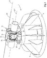
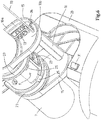
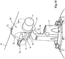
- the device 1 comprises a drop tube 2 having an inlet 3 at an upper end thereof. At a lower end the drop tube 2 opens out above a dispensing pan 4 connected to this drop tube 2.
- the drop tube 2 is equipped with radially extending partitions 5 dividing the dispensing pan in distinctive feeding sections.
- a feed storage like a silo, filled with feed for poultry, like broilers.
- Suitable transportation means are provided, like a rotatable screw or disc chain scraper extending inside the pipe 7, for transporting the feed out of the storage via the conveyor pipe 7 towards the feeding device 1.
- the segment of the pipe 7 is provided with a downwardly directed substantially rectangular outlet 9 (see fig. 6 ) at a lower part of its circumference.
- the inlet 3 of the drop tube 2 is positioned straight underneath this outlet 9 in a feeding position of the device 1 as shown in fig. 1 and 3 .
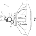
- the feeding device 1 is attached to the pipe 7 by means of an attachment part 10.
- This attachment part 10 comprises two semi-circular halves 10a, 10b which together delimit a substantially cylindrical recess having a central axis 11.
- the halves 10a, 10b are clicked together around the pipe 7 at the location of the outlet 9 by means of a suitable snap connection 13.
- the attachment part 10 is able to rotate as a hinge around the pipe 7. With this the central axis 11 of the attachment part 10 is the same as the longitudinal axis 8 of the segment of the pipe 7.
- the attachment part 10 further comprises two radially outward projecting ears 15. Between those ears 15 a hinge connection 16 is provided.
- the hinge connection 16 has a central axis 17 which extends at a distance h1 parallel to the axis 8, 11. Furthermore the hinge connection is positioned at a distance h2 above the outer circumference of the pipe 7.
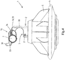
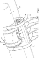
- the drop tube 2 at its upper side is provided with a recessed segment 20 (see fig. 4 ). At its outer side this recessed segment 20 extends in between the ears 15 and is connected to the hinge connection 16. At its inner side this recessed segment 20 connects to the drop tube 2 at the position of its inlet 3. Between the hinge connection 16 and the inlet 3 a distance h3 is present.
- the attachment part 10 delimits a passage 22 in between two ring-shaped wall parts 23. During a rotation of the attachment part 10 around the pipe 7, those wall parts 23 slide along outwardly projecting lips 25 of the pipe 7 which delimit the outlet 9 sideways.
- the attachment part 10 further is provided with an integral valve 27.
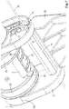
- the valve 27 is formed by a curved plate which is sealingly slideable along an outer circumference of the conveyor pipe 7 during rotation of the attachment part 10. With this the valve 27 is dimensioned such that it fits sliding in between the two lips 25 and is able to fully cover/block the outlet 9 in a cleaning position of the device 1 as shown in fig. 2 , 5 and 8 .
- the attachment part 10 is provided with first locking means 29 provided at arms 30 which in the position as shown in fig. 1 and 3 locks with complementary second locking means 31 provided on the drop tube 2.
- a tensioned wire 33 is placed above the pipe 7.
- the attachment part 10 is hooked to the wire 33 via grooves 34 inside the ears 15. In the hooked position the wire 33 extends through the hinge connection 16.
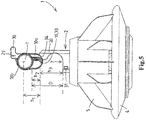
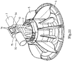
- the feeding device 1 can now be easily moved from the feeding position as shown in fig. 1 and 3 into the cleaning position as shown in fig. 2 , 5 and 8 .
- This can be done by first releasing the tension of the wire 33 and then unlocking the locking means 29, 31 by pushing the arms 30 somewhat outward.
- the attachment part 10 can then be rotated around the pipe 7 in the clockwise direction in the view of fig. 3-5 .
- the hinge connection 16 starts to move from an upper position towards a lower position, and with this movement takes along the drop tube 2 with it.
- the inlet 3 of the drop tube 2 then comes to lie at a distance D underneath the pipe 7. This distance D is substantially equal to h2+h3.
- the valve 27 gets to close off the outlet 9 entirely in this cleaning position.
- the sliding of the valve 27 from the feeding position towards the cleaning position can clearly be seen in the enlarged views of fig. 6-8 .
- the feeding device 1 In the cleaning position the feeding device 1 has the freedom to swing back and forth around the hinge connection 16, while at the same time, owing to the distance D, the inlet 3 has been made accessible from above.
- a farmer can now easily hose the entire feeding device 1 clean from above.
- the farmer In particular it is then possible for the farmer to hose clean the critical inner side of the drop tube 2 including its transition towards the pan 4 without having to bend over or the like.
- the inner and outer sides of the attachment part 10 and the outer side of the pipe 7 can then be hosed clean as well. Finally it is possible to flush clean the pipe 7 with water without having the water prematurely leaking out via the outlet 9.
- the farmer can swing the feeding device 1 backwards such that all the water can run out of the pan 4. Then the feeding device 1 can be brought back into its feeding position by means of a simple rotation of the attachment part 10 in the counter-clockwise direction in the view of fig. 3-5 , until the locking means 29, 31 get locked to each other again. After that the wire 33 can be tensioned again and the system is ready for transporting feed out of the storage via the pipe 7 towards the feeding devices 1.
- the outlet 9 is automatically brought back in flow communication with the inlet 3 again, because the passage 22 gets aligned with the outlet 9 while at the same time the inlet 3 gets positioned closely underneath the passage 22 and outlet 9 respectively.
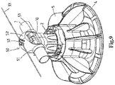
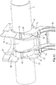
- a variant is shown of which similar parts have been given the same reference numerals.
- a top-piece 50 is provided which fits around the pipe 7 by means of two mounting rings 51.
- a bridging section 52 extends with a play over the attachment part 10.
- the bridging section 52 is provided with grooves 53 into which the wire 33 can be hooked.
- a locking lip 54 is provided which is movable between a locked and an unlocked position. In fig. 10 the unlocked position is shown.
- the top-piece 50 extends with such a play over the attachment part 10 and fits to the pipe 7 sideways of the attachment part 10, that, in the unlocked position of the lip 54, the attachment part 10 is able to freely rotate from the feeding position ( fig. 9 ) towards the cleaning position ( fig. 10 ) and vice versa. During such rotation, the top-piece 50 and thus also the wire 33 are well able to remain in position without starting to co-rotate with the attachment part 10.
- the attachment part 10 here comprises two semi-circular halves 10a, 10b which at one end are hingedly connected to each other by means of a film hinge 55 while at another end they are clicked together around the pipe 7 at the location of the outlet 9 by means of a suitable releasable connection 56. Also it can be seen here that the attachment part 10 grips with two hinge hooks 57 around complementary hinge shafts 58 of the drop tube 2. Together the hooks 57 and shafts 58 form the hinge connection 16 (see also fig. 11 ).
- the device may be of another type like an "oval" type having an oval pan seen in top view, and the several parts of the device may be given any other desired shape or dimension.
- the various components of the feeding device are made out of plastic.
- Other suitable materials are also possible.
- the attachment part making a turn of 180 degrees between its feeding and cleaning positions, it is also possible to provide for a bigger or smaller rotation angle between those two positions like for example one of 90 or one of 270 degrees.
- the hinge connection with the drop tube inlet moving between an upper and a lower position relative to the pipe it is also possible for them to move between other positions, like for example between a left and a right position.
- the inlet in one of both positions gets distanced from the pipe and thus gets accessible from above, this is all possible.
- the valve being integrally formed together with the rotatable attachment part, it is also possible to provide for a separate valve element which can be operated independent of the attachment part.
- the conveyor line can also be formed by another type of elongated distribution means like one that is substantially open at its upper side, for example a trough.
- a multifunctional feeding system is achieved which can be thoroughly cleaned periodically in a simple and cost-effective manner.
- the system is friendly to the animals and beneficial for the farmer.
Landscapes
- Life Sciences & Earth Sciences (AREA)
- Environmental Sciences (AREA)
- Birds (AREA)
- Animal Husbandry (AREA)
- Biodiversity & Conservation Biology (AREA)
- Feeding And Watering For Cattle Raising And Animal Husbandry (AREA)
Claims (15)
- Futterverteilungssystem zum Füttern von Geflügel, das Folgendes umfasst:- einen Futterspeicher;- mindestens eine Förderleitung (7) mit einer Anzahl voneinander beabstandeter Auslässe (9);- eine Anzahl von Fütterungsvorrichtungen (1), die jeweils eine napfförmige Ausgabeschale (4) und eine Futterfallrohr (2) aufweisen, das oberhalb eines mittigen Teils der Schale (4) öffnet; und- ein Transportmittel zum Transportieren von Futter aus dem Speicher über die Förderleitung (7) in Richtung der jeweiligen Fütterungsvorrichtungen (1),wobei jede Fütterungsvorrichtung (1) mit einem Einlass (3) ihres Fallrohres (2), der unter einem der Auslässe (9) positioniert ist, an der Förderleitung (7) angebracht ist, und
wobei jede Fütterungsvorrichtung (1) einen Befestigungsteil (10) hat, der um eine Längsachse (8) der Förderleitung (7) herum drehbar ist,
dadurch gekennzeichnet, dass
der Befestigungsteil (10) von dem Fallrohr (2) getrennt ist, wobei das Fallrohr (2) mittels einer Gelenkverbindung (16) an dem Befestigungsteil (10) angelenkt ist,
wobei der Befestigungsteil (10) zusammen mit der Gelenkverbindung (16) am Fallrohr (2) zwischen einer Fütterungs- und einer Reinigungsposition um die Förderleitung (7) drehbar ist, wobei der Einlass (3) des Fallrohres (2) von dem Auslass (9) der Förderleitung (7) beabstandet wird, wenn der Befestigungsteil (10) zusammen mit der Gelenkverbindung (16) am Fallrohr (2) aus der Fütterungsposition in die Reinigungsposition gedreht wird. - Futterverteilungssystem nach Anspruch 1, wobei der Befestigungsteil (10) einen Durchgang (22) umfasst, der sich vor dem Auslass (9) der Förderleitung (7) in die Fütterungsposition drehen kann, und der Befestigungsteil (10) ein Ventilelement (27) umfasst, das sich vor dem Auslass (9) der Förderleitung (7) in die Reinigungsposition drehen kann.
- Futterverteilungssystem nach Anspruch 2, wobei das Ventilelement (27) eine gekrümmte Platte umfasst, die in abdichtender Weise entlang eines Außenumfangs der Förderleitung (7) gleitbar ist.
- Futterverteilungssystem nach einem der vorangehenden Ansprüche, wobei die Gelenkverbindung (16) in der Fütterungsposition eine obere Position relativ zu der Förderleitung (7) einnimmt und in der Reinigungsposition eine untere Position relativ zu der Förderleitung (7) einnimmt.
- Futterverteilungssystem nach einem der vorangehenden Ansprüche, wobei ein lösbares Verriegelungsmittel (29, 31) zwischen dem Fallrohr (2) und dem Befestigungsteil (10) angeordnet ist, um sie in der Fütterungsposition in lösbarer Weise miteinander zu verriegeln.
- Futterverteilungssystem nach einem der vorangehenden Ansprüche, wobei das Fallrohr (2) an seiner Oberseite mit einem ausgesparten Segment (20) versehen ist, das in der Fütterungsposition um die Förderleitung (7) bzw. das Befestigungsteil (10) herum greift, wobei die Gelenkverbindung (16) an einem oberen Teil des ausgesparten Segments (20) angeordnet ist.
- Futterverteilungssystem nach einem der vorangehenden Ansprüche, wobei der Befestigungsteil (10) zwei Hälften (10a, 10b) umfasst, die jeweils im Wesentlichen ein Segment der Förderleitung (7) mit halbkreisförmigem Querschnitt begrenzen.
- Futterverteilungssystem nach Anspruch 7, wobei die zwei Hälften (10a, 10b) aneinander angelenkt sind, insbesondere mittels eines Filmscharniers (55).
- Futterverteilungssystem nach einem der vorangehenden Ansprüche, wobei die Förderleitung (7), in einer Längsrichtung der Förderleitung (7), auf gegenüberliegenden Seiten des Auslasses (9) mit nach außen hervorstehenden Lippen (25) versehen ist, an denen entlang Umfangswandteile (23) des Befestigungsteils (10) geführt werden.
- Futterverteilungssystem nach einem der vorangehenden Ansprüche 1 - 9, wobei oberhalb der Förderleitung (7) ein Draht (33) gespannt werden kann, wobei der Befestigungsteil (10) an dem Draht (33) eingehängt wird, wobei sich insbesondere der Draht (33) zwischen dem Fallrohr (2) und dem Befestigungsteil (10) im Wesentlichen durch die Gelenkverbindung (16) hindurch erstreckt.
- Futterverteilungssystem nach einem der vorangehenden Ansprüche 1 - 9, wobei ein Kopfstück (50) mit der Förderleitung (7) verbunden ist, um einen Draht (33) damit zu verbinden, wobei der Draht (33) oberhalb der Förderleitung (7) gespannt werden kann, wobei der Befestigungsteil (10) relativ zu dem Kopfstück (50) drehbar ist, insbesondere in eine entriegelte Position eines Verriegelungsmittels zwischen dem Kopfstück (50) und dem Befestigungsteil (10).
- Fütterungsvorrichtung (1) für Geflügel, insbesondere zur Verwendung in einem Futterverteilungssystem nach einem der vorangehenden Ansprüche, die Folgendes umfasst:- eine napfförmige Ausgabeschale (4);- ein Futterfallrohr (2), das oberhalb eines mittigen Teils der Schale (4) öffnet; und- einen Befestigungsteil (10), der eine Aussparung zum drehbar Greifen um eine Längsachse (8) einer Förderleitung (7) herum begrenzt,dadurch gekennzeichnet, dass
der Befestigungsteil (10) von dem Fallrohr (2) getrennt ist, wobei das Fallrohr (2) mittels einer Gelenkverbindung (16) an dem Befestigungsteil (10) angelenkt ist, wobei der Befestigungsteil (10) und das Fallrohr (2) um die Gelenkverbindung (16) herum aus einer Fütterungsposition in eine Reinigungsposition aufgeschwenkt werden können, wobei der Einlass (3) des Fallrohres (2) in dieser Reinigungsposition von dem Befestigungsteil (10) beabstandet wird. - Fütterungsvorrichtung nach Anspruch 12, wobei der Befestigungsteil (10) einen Durchgang (22) umfasst, der vor einem Auslass (9) der Förderleitung (7) in die Fütterungsposition drehbar ist, und der Befestigungsteil (10) ein Ventilelement (27) umfasst, das vor dem Auslass (9) der Förderleitung (7) in die Reinigungsposition drehbar ist.
- Verfahren zum Ausführen einer Reinigungsoperation an einer oder mehreren Fütterungsvorrichtungen (1) eines Futterverteilungssystems für Geflügel nach einem der vorangehenden Ansprüche, das folgende Schritte umfasst:- Drehen des Befestigungsteils (10) der Fütterungsvorrichtung (1) um die Förderleitung (7) herum aus der Fütterungsposition in Richtung der Reinigungsposition, dergestalt, dass der Einlass (3) des Fallrohres (2) von dem Befestigungsteil (10) bzw. dem Auslass (9) der Förderleitung (7) beabstandet wird;- Sauberspritzen der Fütterungsvorrichtung (1), einschließlich des Fallrohres (2), mit einem Schlauch; und- Drehen des Befestigungsteils (10) der Fütterungsvorrichtung (1) um die Förderleitung (7) herum aus der Reinigungsposition zurück in die Fütterungsposition, dergestalt, dass der Einlass (3) des Fallrohres (2) nahe dem Befestigungsteil (10) bzw. dem Auslass (9) der Förderleitung (7) zu liegen kommt.
- Verfahren nach Anspruch 14, wobei während des Schrittes des Drehens des Befestigungsteils (10) der Fütterungsvorrichtung (1) in Richtung der Reinigungsposition ein Ventilelement (27) in eine Position vor dem Auslass (9) der Förderleitung (7) gelangt.
Applications Claiming Priority (2)
| Application Number | Priority Date | Filing Date | Title |
|---|---|---|---|
| NL2010765A NL2010765C2 (en) | 2013-05-07 | 2013-05-07 | Poultry feed distribution system with feeding devices having rotatable attachment parts with drop tubes hingedly connected thereto. |
| PCT/EP2014/059298 WO2014180881A1 (en) | 2013-05-07 | 2014-05-07 | Poultry feed distribution system with feeding devices having rotatable attachment parts with drop tubes hingedly connected thereto |
Publications (2)
| Publication Number | Publication Date |
|---|---|
| EP2993976A1 EP2993976A1 (de) | 2016-03-16 |
| EP2993976B1 true EP2993976B1 (de) | 2016-12-21 |
Family
ID=48670743
Family Applications (1)
| Application Number | Title | Priority Date | Filing Date |
|---|---|---|---|
| EP14722658.3A Active EP2993976B1 (de) | 2013-05-07 | 2014-05-07 | Geflügelfutterverteilungssystem mit fütterungseinrichtungen mit drehbaren anbauteilen mit daran befestigten schwenkbaren fallrohren |
Country Status (12)
| Country | Link |
|---|---|
| US (1) | US9937534B2 (de) |
| EP (1) | EP2993976B1 (de) |
| JP (1) | JP6320516B2 (de) |
| CN (1) | CN105407713B (de) |
| AU (1) | AU2014264634B2 (de) |
| BR (1) | BR112015027933B1 (de) |
| ES (1) | ES2619362T3 (de) |
| IL (1) | IL242486B (de) |
| MX (1) | MX366052B (de) |
| NL (1) | NL2010765C2 (de) |
| RU (1) | RU2653075C2 (de) |
| WO (1) | WO2014180881A1 (de) |
Families Citing this family (12)
| Publication number | Priority date | Publication date | Assignee | Title |
|---|---|---|---|---|
| US9392772B2 (en) * | 2014-10-01 | 2016-07-19 | Valco Companies, Inc. | Poultry feeder storage system |
| US9591833B1 (en) | 2014-10-10 | 2017-03-14 | Southwest Agri-Plastics, Inc. | Storage system for chicken feeders |
| EP3270687A4 (de) * | 2015-03-20 | 2019-01-02 | CTB Inc. | Vorrichtung zur ausgabe von anfangsfutter für küken |
| USD804109S1 (en) * | 2015-06-29 | 2017-11-28 | Sistemas Agropecuarios Jat, S.A. De C.V. | Modular bird feeder |
| USD786511S1 (en) * | 2015-08-26 | 2017-05-09 | Francisco Javier Septien Prieto | Shutter for a bird feeder |
| DK179166B1 (da) | 2016-05-27 | 2018-01-02 | Landmeco Ølgod As | Fremgangsmåde til fyldning af foderskål samt foderanlæg |
| FR3071383B1 (fr) * | 2017-09-26 | 2020-01-03 | Elevage Service | Mangeoire pour canards |
| WO2019079712A1 (en) | 2017-10-20 | 2019-04-25 | University Of Tennessee Research Foundation | METHOD AND APPARATUS FOR ADDITIONAL POWER SUPPLY LOADED BY A SPRING |
| USD952265S1 (en) * | 2019-07-11 | 2022-05-17 | Francisco Javier Septien Prieto | Industrial food dispenser model for animals |
| KR102523241B1 (ko) * | 2020-09-18 | 2023-04-18 | 송상호 | 가금류용 사료통 |
| CN113508761A (zh) * | 2021-08-12 | 2021-10-19 | 徐菲 | 一种散养养鸡场用自动化喂料装置 |
| CN113774466B (zh) * | 2021-08-23 | 2022-08-23 | 昆山硕凯自动化科技有限公司 | 一种挂镀生产线 |
Family Cites Families (20)
| Publication number | Priority date | Publication date | Assignee | Title |
|---|---|---|---|---|
| JPS5038455Y2 (de) * | 1971-08-28 | 1975-11-07 | ||
| JPS5849210B2 (ja) * | 1977-03-14 | 1983-11-02 | 株式会社中嶋製作所 | 養鶏用給飼装置のシヤツタ− |
| JPS5742295Y2 (de) * | 1979-09-14 | 1982-09-17 | ||
| US4834026A (en) | 1988-02-01 | 1989-05-30 | Ctb, Inc. | Poultry feeder assembly |
| NL8902461A (nl) | 1989-10-04 | 1991-05-01 | Roxell Nv | Instelbare voederinrichting voor pluimvee. |
| US5101766A (en) * | 1990-05-30 | 1992-04-07 | Runion Derwood L | Feeder pan |
| US5092274A (en) * | 1990-10-30 | 1992-03-03 | Ctb, Inc. | Poultry feeder |
| WO1994013130A2 (en) | 1992-12-15 | 1994-06-23 | Grain Systems, Inc. | Poultry feeder |
| AUPN069895A0 (en) * | 1995-01-23 | 1995-02-16 | F & M Horwood Nominees Pty Ltd | A male fowl feeder |
| US5875733A (en) | 1997-07-25 | 1999-03-02 | Chen; Ai-Mei | Feeding device for poultry |
| US5927232A (en) * | 1997-08-22 | 1999-07-27 | Gsi Group, Inc. | Poultry feeder |
| DK199900057U4 (da) * | 1999-02-09 | 2000-06-23 | Landmeco Oelgod As | Foderskål samt fodringsanlæg til fjerkræ, især høns og kyllinger |
| NL1016638C2 (nl) | 2000-11-17 | 2002-05-22 | Roxell Nv | Voerdistributiesysteem voor gevogelte. |
| NL1017274C2 (nl) * | 2001-02-02 | 2002-08-05 | Nicolaas Andreas Maria Korsten | Stalinrichting alsmede werkwijze voor het bedienen van een dergelijke stalinrichting. |
| DE10164100C1 (de) * | 2001-12-24 | 2003-04-03 | Big Dutchman Int Gmbh | Vorrichtung für die Fütterung von Geflügel, insbesondere Mastgeflügel, vorzugsweise Broiler |
| DE10164122C1 (de) | 2001-12-24 | 2003-05-15 | Big Dutchman Int Gmbh | Vorrichtung für die Fütterung von Geflügel, insbesondere Mastgeflügel, vorzugsweise Broiler |
| CN201585327U (zh) | 2009-12-25 | 2010-09-22 | 贺恒志 | 一种种家禽喂料器 |
| JP4602473B1 (ja) * | 2010-05-13 | 2010-12-22 | 株式会社中嶋製作所 | スライドネック |
| JP4602472B1 (ja) * | 2010-05-13 | 2010-12-22 | 株式会社中嶋製作所 | スライドネック |
| CN103039378A (zh) | 2012-12-29 | 2013-04-17 | 李晗 | 鸡饲料自动喂料车 |
-
2013
- 2013-05-07 NL NL2010765A patent/NL2010765C2/en not_active IP Right Cessation
-
2014
- 2014-05-07 CN CN201480026001.1A patent/CN105407713B/zh active Active
- 2014-05-07 US US14/888,953 patent/US9937534B2/en active Active
- 2014-05-07 WO PCT/EP2014/059298 patent/WO2014180881A1/en not_active Ceased
- 2014-05-07 RU RU2015147603A patent/RU2653075C2/ru active
- 2014-05-07 JP JP2016512353A patent/JP6320516B2/ja active Active
- 2014-05-07 EP EP14722658.3A patent/EP2993976B1/de active Active
- 2014-05-07 AU AU2014264634A patent/AU2014264634B2/en active Active
- 2014-05-07 MX MX2015015330A patent/MX366052B/es active IP Right Grant
- 2014-05-07 ES ES14722658.3T patent/ES2619362T3/es active Active
- 2014-05-07 BR BR112015027933-3A patent/BR112015027933B1/pt active IP Right Grant
-
2015
- 2015-11-05 IL IL242486A patent/IL242486B/en active IP Right Grant
Non-Patent Citations (1)
| Title |
|---|
| None * |
Also Published As
| Publication number | Publication date |
|---|---|
| EP2993976A1 (de) | 2016-03-16 |
| JP2016517692A (ja) | 2016-06-20 |
| WO2014180881A1 (en) | 2014-11-13 |
| MX2015015330A (es) | 2016-06-02 |
| BR112015027933B1 (pt) | 2020-10-27 |
| MX366052B (es) | 2019-06-26 |
| IL242486B (en) | 2018-07-31 |
| US9937534B2 (en) | 2018-04-10 |
| CN105407713B (zh) | 2018-04-13 |
| AU2014264634A1 (en) | 2015-11-05 |
| RU2015147603A3 (de) | 2018-03-15 |
| RU2653075C2 (ru) | 2018-05-07 |
| NL2010765C2 (en) | 2014-11-10 |
| JP6320516B2 (ja) | 2018-05-09 |
| RU2015147603A (ru) | 2017-06-13 |
| CN105407713A (zh) | 2016-03-16 |
| ES2619362T3 (es) | 2017-06-26 |
| US20160073615A1 (en) | 2016-03-17 |
| AU2014264634B2 (en) | 2018-02-08 |
Similar Documents
| Publication | Publication Date | Title |
|---|---|---|
| EP2993976B1 (de) | Geflügelfutterverteilungssystem mit fütterungseinrichtungen mit drehbaren anbauteilen mit daran befestigten schwenkbaren fallrohren | |
| CN102361549B (zh) | 用于自动清洁旋转挤奶平台的挤奶机杯的装置 | |
| US8074600B2 (en) | Rotary parlour for automatic milking of animals | |
| KR100231786B1 (ko) | 가금사육기및그사육방법 | |
| EP0260292B1 (de) | Verbesserungen an gefriervorrichtung | |
| CA2991192C (en) | Chick starter feed outlet device | |
| EP2547197B1 (de) | Positionierungsvorrichtung | |
| US12193415B2 (en) | Water dispenser apparatus for use by poultry | |
| NL2001841C2 (en) | Feed distribution system for feeding poultry having individually adjustable indexing means. | |
| WO2026057135A1 (en) | Feeding system comprising feeding devices with oblique surfaces | |
| CN204907446U (zh) | 一种箱式挤奶单元 | |
| CN220712500U (zh) | 一种具备自动清粪功能的家禽养殖笼设备 | |
| EP3151656B1 (de) | Anordnung einer karussellmelkanlage | |
| CN215543480U (zh) | 一种便于清洁的猪槽 | |
| US20150320006A1 (en) | System and method for removing disinfectant solution from udders and teats of cows | |
| CN117136877A (zh) | 一种麻黄鸡喂食装置 | |
| WO2014038997A1 (en) | A support arm device for a milking member and a milking parlour comprising such a support arm device | |
| EP3346829B1 (de) | Tiertränke | |
| HK40002275B (zh) | 填充饲喂盘的方法以及饲喂系统 | |
| TH6767B (th) | ชุดประกอบถาดสำหรับให้อาหารสัตว์ปีก |
Legal Events
| Date | Code | Title | Description |
|---|---|---|---|
| PUAI | Public reference made under article 153(3) epc to a published international application that has entered the european phase |
Free format text: ORIGINAL CODE: 0009012 |
|
| 17P | Request for examination filed |
Effective date: 20151119 |
|
| AK | Designated contracting states |
Kind code of ref document: A1 Designated state(s): AL AT BE BG CH CY CZ DE DK EE ES FI FR GB GR HR HU IE IS IT LI LT LU LV MC MK MT NL NO PL PT RO RS SE SI SK SM TR |
|
| AX | Request for extension of the european patent |
Extension state: BA ME |
|
| DAX | Request for extension of the european patent (deleted) | ||
| GRAP | Despatch of communication of intention to grant a patent |
Free format text: ORIGINAL CODE: EPIDOSNIGR1 |
|
| RIC1 | Information provided on ipc code assigned before grant |
Ipc: B08B 3/02 20060101ALI20160801BHEP Ipc: A01K 39/012 20060101AFI20160801BHEP |
|
| INTG | Intention to grant announced |
Effective date: 20160817 |
|
| GRAS | Grant fee paid |
Free format text: ORIGINAL CODE: EPIDOSNIGR3 |
|
| GRAA | (expected) grant |
Free format text: ORIGINAL CODE: 0009210 |
|
| AK | Designated contracting states |
Kind code of ref document: B1 Designated state(s): AL AT BE BG CH CY CZ DE DK EE ES FI FR GB GR HR HU IE IS IT LI LT LU LV MC MK MT NL NO PL PT RO RS SE SI SK SM TR |
|
| REG | Reference to a national code |
Ref country code: GB Ref legal event code: FG4D |
|
| REG | Reference to a national code |
Ref country code: CH Ref legal event code: EP |
|
| REG | Reference to a national code |
Ref country code: IE Ref legal event code: FG4D |
|
| REG | Reference to a national code |
Ref country code: AT Ref legal event code: REF Ref document number: 854627 Country of ref document: AT Kind code of ref document: T Effective date: 20170115 |
|
| REG | Reference to a national code |
Ref country code: NL Ref legal event code: FP |
|
| REG | Reference to a national code |
Ref country code: DE Ref legal event code: R096 Ref document number: 602014005714 Country of ref document: DE |
|
| PG25 | Lapsed in a contracting state [announced via postgrant information from national office to epo] |
Ref country code: LV Free format text: LAPSE BECAUSE OF FAILURE TO SUBMIT A TRANSLATION OF THE DESCRIPTION OR TO PAY THE FEE WITHIN THE PRESCRIBED TIME-LIMIT Effective date: 20161221 |
|
| REG | Reference to a national code |
Ref country code: LT Ref legal event code: MG4D |
|
| PG25 | Lapsed in a contracting state [announced via postgrant information from national office to epo] |
Ref country code: NO Free format text: LAPSE BECAUSE OF FAILURE TO SUBMIT A TRANSLATION OF THE DESCRIPTION OR TO PAY THE FEE WITHIN THE PRESCRIBED TIME-LIMIT Effective date: 20170321 Ref country code: GR Free format text: LAPSE BECAUSE OF FAILURE TO SUBMIT A TRANSLATION OF THE DESCRIPTION OR TO PAY THE FEE WITHIN THE PRESCRIBED TIME-LIMIT Effective date: 20170322 Ref country code: LT Free format text: LAPSE BECAUSE OF FAILURE TO SUBMIT A TRANSLATION OF THE DESCRIPTION OR TO PAY THE FEE WITHIN THE PRESCRIBED TIME-LIMIT Effective date: 20161221 Ref country code: SE Free format text: LAPSE BECAUSE OF FAILURE TO SUBMIT A TRANSLATION OF THE DESCRIPTION OR TO PAY THE FEE WITHIN THE PRESCRIBED TIME-LIMIT Effective date: 20161221 |
|
| REG | Reference to a national code |
Ref country code: AT Ref legal event code: MK05 Ref document number: 854627 Country of ref document: AT Kind code of ref document: T Effective date: 20161221 |
|
| REG | Reference to a national code |
Ref country code: FR Ref legal event code: PLFP Year of fee payment: 4 |
|
| PG25 | Lapsed in a contracting state [announced via postgrant information from national office to epo] |
Ref country code: HR Free format text: LAPSE BECAUSE OF FAILURE TO SUBMIT A TRANSLATION OF THE DESCRIPTION OR TO PAY THE FEE WITHIN THE PRESCRIBED TIME-LIMIT Effective date: 20161221 Ref country code: RS Free format text: LAPSE BECAUSE OF FAILURE TO SUBMIT A TRANSLATION OF THE DESCRIPTION OR TO PAY THE FEE WITHIN THE PRESCRIBED TIME-LIMIT Effective date: 20161221 Ref country code: FI Free format text: LAPSE BECAUSE OF FAILURE TO SUBMIT A TRANSLATION OF THE DESCRIPTION OR TO PAY THE FEE WITHIN THE PRESCRIBED TIME-LIMIT Effective date: 20161221 |
|
| REG | Reference to a national code |
Ref country code: ES Ref legal event code: FG2A Ref document number: 2619362 Country of ref document: ES Kind code of ref document: T3 Effective date: 20170626 |
|
| PG25 | Lapsed in a contracting state [announced via postgrant information from national office to epo] |
Ref country code: CZ Free format text: LAPSE BECAUSE OF FAILURE TO SUBMIT A TRANSLATION OF THE DESCRIPTION OR TO PAY THE FEE WITHIN THE PRESCRIBED TIME-LIMIT Effective date: 20161221 Ref country code: EE Free format text: LAPSE BECAUSE OF FAILURE TO SUBMIT A TRANSLATION OF THE DESCRIPTION OR TO PAY THE FEE WITHIN THE PRESCRIBED TIME-LIMIT Effective date: 20161221 Ref country code: IS Free format text: LAPSE BECAUSE OF FAILURE TO SUBMIT A TRANSLATION OF THE DESCRIPTION OR TO PAY THE FEE WITHIN THE PRESCRIBED TIME-LIMIT Effective date: 20170421 Ref country code: SK Free format text: LAPSE BECAUSE OF FAILURE TO SUBMIT A TRANSLATION OF THE DESCRIPTION OR TO PAY THE FEE WITHIN THE PRESCRIBED TIME-LIMIT Effective date: 20161221 Ref country code: RO Free format text: LAPSE BECAUSE OF FAILURE TO SUBMIT A TRANSLATION OF THE DESCRIPTION OR TO PAY THE FEE WITHIN THE PRESCRIBED TIME-LIMIT Effective date: 20161221 |
|
| PG25 | Lapsed in a contracting state [announced via postgrant information from national office to epo] |
Ref country code: SM Free format text: LAPSE BECAUSE OF FAILURE TO SUBMIT A TRANSLATION OF THE DESCRIPTION OR TO PAY THE FEE WITHIN THE PRESCRIBED TIME-LIMIT Effective date: 20161221 Ref country code: AT Free format text: LAPSE BECAUSE OF FAILURE TO SUBMIT A TRANSLATION OF THE DESCRIPTION OR TO PAY THE FEE WITHIN THE PRESCRIBED TIME-LIMIT Effective date: 20161221 Ref country code: BG Free format text: LAPSE BECAUSE OF FAILURE TO SUBMIT A TRANSLATION OF THE DESCRIPTION OR TO PAY THE FEE WITHIN THE PRESCRIBED TIME-LIMIT Effective date: 20170321 Ref country code: PT Free format text: LAPSE BECAUSE OF FAILURE TO SUBMIT A TRANSLATION OF THE DESCRIPTION OR TO PAY THE FEE WITHIN THE PRESCRIBED TIME-LIMIT Effective date: 20170421 Ref country code: PL Free format text: LAPSE BECAUSE OF FAILURE TO SUBMIT A TRANSLATION OF THE DESCRIPTION OR TO PAY THE FEE WITHIN THE PRESCRIBED TIME-LIMIT Effective date: 20161221 Ref country code: LU Free format text: LAPSE BECAUSE OF NON-PAYMENT OF DUE FEES Effective date: 20170531 |
|
| REG | Reference to a national code |
Ref country code: DE Ref legal event code: R097 Ref document number: 602014005714 Country of ref document: DE |
|
| PLBE | No opposition filed within time limit |
Free format text: ORIGINAL CODE: 0009261 |
|
| STAA | Information on the status of an ep patent application or granted ep patent |
Free format text: STATUS: NO OPPOSITION FILED WITHIN TIME LIMIT |
|
| 26N | No opposition filed |
Effective date: 20170922 |
|
| PG25 | Lapsed in a contracting state [announced via postgrant information from national office to epo] |
Ref country code: DK Free format text: LAPSE BECAUSE OF FAILURE TO SUBMIT A TRANSLATION OF THE DESCRIPTION OR TO PAY THE FEE WITHIN THE PRESCRIBED TIME-LIMIT Effective date: 20161221 |
|
| REG | Reference to a national code |
Ref country code: CH Ref legal event code: PL |
|
| PG25 | Lapsed in a contracting state [announced via postgrant information from national office to epo] |
Ref country code: MC Free format text: LAPSE BECAUSE OF FAILURE TO SUBMIT A TRANSLATION OF THE DESCRIPTION OR TO PAY THE FEE WITHIN THE PRESCRIBED TIME-LIMIT Effective date: 20161221 |
|
| REG | Reference to a national code |
Ref country code: IE Ref legal event code: MM4A |
|
| PG25 | Lapsed in a contracting state [announced via postgrant information from national office to epo] |
Ref country code: CH Free format text: LAPSE BECAUSE OF NON-PAYMENT OF DUE FEES Effective date: 20170531 Ref country code: SI Free format text: LAPSE BECAUSE OF FAILURE TO SUBMIT A TRANSLATION OF THE DESCRIPTION OR TO PAY THE FEE WITHIN THE PRESCRIBED TIME-LIMIT Effective date: 20161221 Ref country code: LI Free format text: LAPSE BECAUSE OF NON-PAYMENT OF DUE FEES Effective date: 20170531 |
|
| PG25 | Lapsed in a contracting state [announced via postgrant information from national office to epo] |
Ref country code: LU Free format text: LAPSE BECAUSE OF NON-PAYMENT OF DUE FEES Effective date: 20170507 |
|
| PG25 | Lapsed in a contracting state [announced via postgrant information from national office to epo] |
Ref country code: IE Free format text: LAPSE BECAUSE OF NON-PAYMENT OF DUE FEES Effective date: 20170507 |
|
| REG | Reference to a national code |
Ref country code: FR Ref legal event code: PLFP Year of fee payment: 5 |
|
| PG25 | Lapsed in a contracting state [announced via postgrant information from national office to epo] |
Ref country code: MT Free format text: LAPSE BECAUSE OF NON-PAYMENT OF DUE FEES Effective date: 20170507 |
|
| PG25 | Lapsed in a contracting state [announced via postgrant information from national office to epo] |
Ref country code: HU Free format text: LAPSE BECAUSE OF FAILURE TO SUBMIT A TRANSLATION OF THE DESCRIPTION OR TO PAY THE FEE WITHIN THE PRESCRIBED TIME-LIMIT; INVALID AB INITIO Effective date: 20140507 |
|
| PG25 | Lapsed in a contracting state [announced via postgrant information from national office to epo] |
Ref country code: CY Free format text: LAPSE BECAUSE OF FAILURE TO SUBMIT A TRANSLATION OF THE DESCRIPTION OR TO PAY THE FEE WITHIN THE PRESCRIBED TIME-LIMIT Effective date: 20161221 |
|
| PG25 | Lapsed in a contracting state [announced via postgrant information from national office to epo] |
Ref country code: MK Free format text: LAPSE BECAUSE OF FAILURE TO SUBMIT A TRANSLATION OF THE DESCRIPTION OR TO PAY THE FEE WITHIN THE PRESCRIBED TIME-LIMIT Effective date: 20161221 |
|
| PG25 | Lapsed in a contracting state [announced via postgrant information from national office to epo] |
Ref country code: TR Free format text: LAPSE BECAUSE OF FAILURE TO SUBMIT A TRANSLATION OF THE DESCRIPTION OR TO PAY THE FEE WITHIN THE PRESCRIBED TIME-LIMIT Effective date: 20161221 |
|
| PG25 | Lapsed in a contracting state [announced via postgrant information from national office to epo] |
Ref country code: AL Free format text: LAPSE BECAUSE OF FAILURE TO SUBMIT A TRANSLATION OF THE DESCRIPTION OR TO PAY THE FEE WITHIN THE PRESCRIBED TIME-LIMIT Effective date: 20161221 |
|
| P01 | Opt-out of the competence of the unified patent court (upc) registered |
Effective date: 20230512 |
|
| PGFP | Annual fee paid to national office [announced via postgrant information from national office to epo] |
Ref country code: NL Payment date: 20250523 Year of fee payment: 12 |
|
| PGFP | Annual fee paid to national office [announced via postgrant information from national office to epo] |
Ref country code: DE Payment date: 20250519 Year of fee payment: 12 |
|
| PGFP | Annual fee paid to national office [announced via postgrant information from national office to epo] |
Ref country code: GB Payment date: 20250522 Year of fee payment: 12 Ref country code: ES Payment date: 20250616 Year of fee payment: 12 |
|
| PGFP | Annual fee paid to national office [announced via postgrant information from national office to epo] |
Ref country code: IT Payment date: 20250530 Year of fee payment: 12 Ref country code: BE Payment date: 20250520 Year of fee payment: 12 |
|
| PGFP | Annual fee paid to national office [announced via postgrant information from national office to epo] |
Ref country code: FR Payment date: 20250521 Year of fee payment: 12 |