EP2993736A1 - Composant électronique - Google Patents
Composant électronique Download PDFInfo
- Publication number
- EP2993736A1 EP2993736A1 EP14003043.8A EP14003043A EP2993736A1 EP 2993736 A1 EP2993736 A1 EP 2993736A1 EP 14003043 A EP14003043 A EP 14003043A EP 2993736 A1 EP2993736 A1 EP 2993736A1
- Authority
- EP
- European Patent Office
- Prior art keywords
- circuit board
- cable
- wires
- electronic assembly
- assembly according
- Prior art date
- Legal status (The legal status is an assumption and is not a legal conclusion. Google has not performed a legal analysis and makes no representation as to the accuracy of the status listed.)
- Granted
Links
- 239000004020 conductor Substances 0.000 claims abstract description 18
- 238000009413 insulation Methods 0.000 claims description 6
- 241000209035 Ilex Species 0.000 description 3
- 230000008054 signal transmission Effects 0.000 description 3
- 239000000853 adhesive Substances 0.000 description 2
- 230000001070 adhesive effect Effects 0.000 description 2
- 230000008878 coupling Effects 0.000 description 2
- 238000010168 coupling process Methods 0.000 description 2
- 238000005859 coupling reaction Methods 0.000 description 2
- 238000002788 crimping Methods 0.000 description 2
- 238000005538 encapsulation Methods 0.000 description 2
- 238000004519 manufacturing process Methods 0.000 description 2
- 239000002184 metal Substances 0.000 description 2
- 229910000679 solder Inorganic materials 0.000 description 2
- 229910000906 Bronze Inorganic materials 0.000 description 1
- ATJFFYVFTNAWJD-UHFFFAOYSA-N Tin Chemical compound [Sn] ATJFFYVFTNAWJD-UHFFFAOYSA-N 0.000 description 1
- 230000005540 biological transmission Effects 0.000 description 1
- 239000010974 bronze Substances 0.000 description 1
- KUNSUQLRTQLHQQ-UHFFFAOYSA-N copper tin Chemical compound [Cu].[Sn] KUNSUQLRTQLHQQ-UHFFFAOYSA-N 0.000 description 1
- 230000001419 dependent effect Effects 0.000 description 1
- 238000005553 drilling Methods 0.000 description 1
- 239000012777 electrically insulating material Substances 0.000 description 1
- 238000001746 injection moulding Methods 0.000 description 1
- 238000009434 installation Methods 0.000 description 1
- 230000003993 interaction Effects 0.000 description 1
- 238000005304 joining Methods 0.000 description 1
- 239000000463 material Substances 0.000 description 1
- 238000000034 method Methods 0.000 description 1
- 230000003287 optical effect Effects 0.000 description 1
- 238000012858 packaging process Methods 0.000 description 1
Images


Classifications
-
- H—ELECTRICITY
- H01—ELECTRIC ELEMENTS
- H01R—ELECTRICALLY-CONDUCTIVE CONNECTIONS; STRUCTURAL ASSOCIATIONS OF A PLURALITY OF MUTUALLY-INSULATED ELECTRICAL CONNECTING ELEMENTS; COUPLING DEVICES; CURRENT COLLECTORS
- H01R12/00—Structural associations of a plurality of mutually-insulated electrical connecting elements, specially adapted for printed circuits, e.g. printed circuit boards [PCB], flat or ribbon cables, or like generally planar structures, e.g. terminal strips, terminal blocks; Coupling devices specially adapted for printed circuits, flat or ribbon cables, or like generally planar structures; Terminals specially adapted for contact with, or insertion into, printed circuits, flat or ribbon cables, or like generally planar structures
- H01R12/50—Fixed connections
- H01R12/59—Fixed connections for flexible printed circuits, flat or ribbon cables or like structures
- H01R12/62—Fixed connections for flexible printed circuits, flat or ribbon cables or like structures connecting to rigid printed circuits or like structures
-
- H—ELECTRICITY
- H01—ELECTRIC ELEMENTS
- H01R—ELECTRICALLY-CONDUCTIVE CONNECTIONS; STRUCTURAL ASSOCIATIONS OF A PLURALITY OF MUTUALLY-INSULATED ELECTRICAL CONNECTING ELEMENTS; COUPLING DEVICES; CURRENT COLLECTORS
- H01R12/00—Structural associations of a plurality of mutually-insulated electrical connecting elements, specially adapted for printed circuits, e.g. printed circuit boards [PCB], flat or ribbon cables, or like generally planar structures, e.g. terminal strips, terminal blocks; Coupling devices specially adapted for printed circuits, flat or ribbon cables, or like generally planar structures; Terminals specially adapted for contact with, or insertion into, printed circuits, flat or ribbon cables, or like generally planar structures
- H01R12/50—Fixed connections
- H01R12/51—Fixed connections for rigid printed circuits or like structures
- H01R12/53—Fixed connections for rigid printed circuits or like structures connecting to cables except for flat or ribbon cables
-
- B—PERFORMING OPERATIONS; TRANSPORTING
- B60—VEHICLES IN GENERAL
- B60R—VEHICLES, VEHICLE FITTINGS, OR VEHICLE PARTS, NOT OTHERWISE PROVIDED FOR
- B60R16/00—Electric or fluid circuits specially adapted for vehicles and not otherwise provided for; Arrangement of elements of electric or fluid circuits specially adapted for vehicles and not otherwise provided for
- B60R16/02—Electric or fluid circuits specially adapted for vehicles and not otherwise provided for; Arrangement of elements of electric or fluid circuits specially adapted for vehicles and not otherwise provided for electric constitutive elements
- B60R16/023—Electric or fluid circuits specially adapted for vehicles and not otherwise provided for; Arrangement of elements of electric or fluid circuits specially adapted for vehicles and not otherwise provided for electric constitutive elements for transmission of signals between vehicle parts or subsystems
-
- H—ELECTRICITY
- H01—ELECTRIC ELEMENTS
- H01R—ELECTRICALLY-CONDUCTIVE CONNECTIONS; STRUCTURAL ASSOCIATIONS OF A PLURALITY OF MUTUALLY-INSULATED ELECTRICAL CONNECTING ELEMENTS; COUPLING DEVICES; CURRENT COLLECTORS
- H01R12/00—Structural associations of a plurality of mutually-insulated electrical connecting elements, specially adapted for printed circuits, e.g. printed circuit boards [PCB], flat or ribbon cables, or like generally planar structures, e.g. terminal strips, terminal blocks; Coupling devices specially adapted for printed circuits, flat or ribbon cables, or like generally planar structures; Terminals specially adapted for contact with, or insertion into, printed circuits, flat or ribbon cables, or like generally planar structures
- H01R12/50—Fixed connections
- H01R12/51—Fixed connections for rigid printed circuits or like structures
- H01R12/55—Fixed connections for rigid printed circuits or like structures characterised by the terminals
- H01R12/58—Fixed connections for rigid printed circuits or like structures characterised by the terminals terminals for insertion into holes
-
- H—ELECTRICITY
- H01—ELECTRIC ELEMENTS
- H01R—ELECTRICALLY-CONDUCTIVE CONNECTIONS; STRUCTURAL ASSOCIATIONS OF A PLURALITY OF MUTUALLY-INSULATED ELECTRICAL CONNECTING ELEMENTS; COUPLING DEVICES; CURRENT COLLECTORS
- H01R13/00—Details of coupling devices of the kinds covered by groups H01R12/70 or H01R24/00 - H01R33/00
- H01R13/648—Protective earth or shield arrangements on coupling devices, e.g. anti-static shielding
- H01R13/658—High frequency shielding arrangements, e.g. against EMI [Electro-Magnetic Interference] or EMP [Electro-Magnetic Pulse]
- H01R13/6591—Specific features or arrangements of connection of shield to conductive members
- H01R13/65912—Specific features or arrangements of connection of shield to conductive members for shielded multiconductor cable
- H01R13/65914—Connection of shield to additional grounding conductors
-
- H—ELECTRICITY
- H01—ELECTRIC ELEMENTS
- H01R—ELECTRICALLY-CONDUCTIVE CONNECTIONS; STRUCTURAL ASSOCIATIONS OF A PLURALITY OF MUTUALLY-INSULATED ELECTRICAL CONNECTING ELEMENTS; COUPLING DEVICES; CURRENT COLLECTORS
- H01R4/00—Electrically-conductive connections between two or more conductive members in direct contact, i.e. touching one another; Means for effecting or maintaining such contact; Electrically-conductive connections having two or more spaced connecting locations for conductors and using contact members penetrating insulation
- H01R4/02—Soldered or welded connections
-
- H—ELECTRICITY
- H01—ELECTRIC ELEMENTS
- H01R—ELECTRICALLY-CONDUCTIVE CONNECTIONS; STRUCTURAL ASSOCIATIONS OF A PLURALITY OF MUTUALLY-INSULATED ELECTRICAL CONNECTING ELEMENTS; COUPLING DEVICES; CURRENT COLLECTORS
- H01R4/00—Electrically-conductive connections between two or more conductive members in direct contact, i.e. touching one another; Means for effecting or maintaining such contact; Electrically-conductive connections having two or more spaced connecting locations for conductors and using contact members penetrating insulation
- H01R4/10—Electrically-conductive connections between two or more conductive members in direct contact, i.e. touching one another; Means for effecting or maintaining such contact; Electrically-conductive connections having two or more spaced connecting locations for conductors and using contact members penetrating insulation effected solely by twisting, wrapping, bending, crimping, or other permanent deformation
- H01R4/18—Electrically-conductive connections between two or more conductive members in direct contact, i.e. touching one another; Means for effecting or maintaining such contact; Electrically-conductive connections having two or more spaced connecting locations for conductors and using contact members penetrating insulation effected solely by twisting, wrapping, bending, crimping, or other permanent deformation by crimping
-
- H—ELECTRICITY
- H01—ELECTRIC ELEMENTS
- H01R—ELECTRICALLY-CONDUCTIVE CONNECTIONS; STRUCTURAL ASSOCIATIONS OF A PLURALITY OF MUTUALLY-INSULATED ELECTRICAL CONNECTING ELEMENTS; COUPLING DEVICES; CURRENT COLLECTORS
- H01R2201/00—Connectors or connections adapted for particular applications
- H01R2201/26—Connectors or connections adapted for particular applications for vehicles
-
- H—ELECTRICITY
- H05—ELECTRIC TECHNIQUES NOT OTHERWISE PROVIDED FOR
- H05K—PRINTED CIRCUITS; CASINGS OR CONSTRUCTIONAL DETAILS OF ELECTRIC APPARATUS; MANUFACTURE OF ASSEMBLAGES OF ELECTRICAL COMPONENTS
- H05K2201/00—Indexing scheme relating to printed circuits covered by H05K1/00
- H05K2201/09—Shape and layout
- H05K2201/09209—Shape and layout details of conductors
- H05K2201/09654—Shape and layout details of conductors covering at least two types of conductors provided for in H05K2201/09218 - H05K2201/095
- H05K2201/09781—Dummy conductors, i.e. not used for normal transport of current; Dummy electrodes of components
-
- H—ELECTRICITY
- H05—ELECTRIC TECHNIQUES NOT OTHERWISE PROVIDED FOR
- H05K—PRINTED CIRCUITS; CASINGS OR CONSTRUCTIONAL DETAILS OF ELECTRIC APPARATUS; MANUFACTURE OF ASSEMBLAGES OF ELECTRICAL COMPONENTS
- H05K2201/00—Indexing scheme relating to printed circuits covered by H05K1/00
- H05K2201/10—Details of components or other objects attached to or integrated in a printed circuit board
- H05K2201/10007—Types of components
- H05K2201/10189—Non-printed connector
-
- H—ELECTRICITY
- H05—ELECTRIC TECHNIQUES NOT OTHERWISE PROVIDED FOR
- H05K—PRINTED CIRCUITS; CASINGS OR CONSTRUCTIONAL DETAILS OF ELECTRIC APPARATUS; MANUFACTURE OF ASSEMBLAGES OF ELECTRICAL COMPONENTS
- H05K3/00—Apparatus or processes for manufacturing printed circuits
- H05K3/30—Assembling printed circuits with electric components, e.g. with resistor
- H05K3/32—Assembling printed circuits with electric components, e.g. with resistor electrically connecting electric components or wires to printed circuits
- H05K3/34—Assembling printed circuits with electric components, e.g. with resistor electrically connecting electric components or wires to printed circuits by soldering
- H05K3/3447—Lead-in-hole components
Definitions
- the invention relates to an electronic assembly comprising a printed circuit board and a cable, in particular a round cable, which is suitable in particular for the transmission of signals in vehicles, according to claim 1.
- the units in question are used for example in motor vehicles or aircraft and are usually needed in large quantities. For cost-effective provision of appropriate units a simple structure and ease of assembly or assembly are of great importance.
- the invention has for its object to provide an electronic assembly, which is particularly suitable for the transmission of signals or data and can be manufactured with relatively little manufacturing effort.
- the electronic assembly comprises a printed circuit board and a cable, wherein the printed circuit board has at least three first holes, which are arranged according to a predetermined pattern in the printed circuit board.
- the cable in turn has at least three wires arranged around a longitudinal axis of the end of the cable and each comprising an insulation and a conductor.
- the cable has a support clamp, which in turn has a radially outside of the wires arranged fastener. The wires are held by the fastener such that the support bracket is fixed against rotation relative to the wires.
- the cable has a so-called body.
- the cable is designed so that the support bracket is in turn connected rotationally fixed to the body with respect to the longitudinal axis and the body of the course of the wires is deflected so that the ends of the wires are positioned according to the vorgebebenen pattern.
- the conductors are placed in the first holes and electrically contacted with the circuit board. In particular, the conductors are placed in the first holes so that there is a via, so the conductors are inserted through the first holes.
- the cable thus has a plurality of wires which are arranged around a longitudinal axis of the end of the cable, so that the cable can also be referred to in particular as a round cable in which the wires are bundled in a circular manner in a circular jacket, which can be formed as an insulating tube. can be arranged (in contrast to a ribbon cable, in which the wires are arranged linearly side by side).
- the pre-defined pattern after which the ends of the wires are positioned, deviates from a linear pattern.
- the ends of the wires thus span a geometric surface and are not arranged along a line.
- longitudinal axis refers in particular to the end of the cable or to the cable in a stretched form.
- the longitudinal axis of the end of the cable is oriented orthogonal or perpendicular to the circuit board.
- the cable has four wires which are twisted together.
- the cable can also have a screen which comprises, for example, a braided screen.
- the cable can be constructed according to a star quad concept.
- the body has first recesses, wherein the wires are arranged in the first recesses.
- the first recesses are preferably oriented parallel to the longitudinal axis, or run parallel to the longitudinal axis.
- the first recesses may be designed such that the cores are held in a form-fitting manner, for example by an undercut, in the radial direction (with a holding force orthogonal to the longitudinal axis).
- the body has a second recess, in which the support bracket, in particular form-fitting, is received rotationally.
- the cable is thus designed so that the wires are arranged at right angles relative to the support bracket and also due to the interaction of the second recess of the body with the support bracket a right angle orientation between the wires and the support bracket is given.
- the body may be surrounded by a radially outer sleeve.
- the body may be mechanically connected to the sleeve, such as by a catch.
- the sleeve can be rotationally connected to the support bracket.
- the support bracket has a configured as a fork end and the sleeve at least one slot wherein the fork, or a prong of the fork, engages in the at least one slot.
- the sleeve has at least two slots, in which case the fork, in which engages at least two slots, or tines of the fork engage in the at least two slots.
- the electronic assembly is designed so that the wires are surrounded by the sleeve, which is radially outward with respect to the wires.
- the support bracket may be connected to the circuit board, for example by a solder joint or by an adhesive bond.
- the support clamp on a designed as a fork end, which is placed in at least a second bore of the circuit board.
- the fork can be connected to the circuit board, for example by a solder connection, a latch or by an adhesive connection.
- the fork may have a latching hook, which cooperates with the second bore of the circuit board so that the fork or the support clamp is mechanically connected after installation with the circuit board.
- first holes nor the second holes must necessarily be made by a drilling process.
- the term bore a depression or a breakthrough to understand, with such a hole with a round cross-section but can also be configured angular or out-of-round.
- one of the conductors is placed in each one of the first holes, wherein the circuit board has at least one second bore, in which one end of the support bracket is placed.
- the at least one second bore lies outside that surface which is spanned by the centers of the first bores.
- the circuit board has at least three first holes, which are arranged according to the predetermined pattern in the circuit board.
- the given pattern deviates from a linear pattern.
- the first holes (or their centers) so span a geometric surface and are not arranged along a line.
- the circuit board has four first holes, which are arranged according to the predetermined pattern in the circuit board.
- the predetermined pattern is designed so that the four first holes lie on the corners of a (imaginary) square.
- the circuit board has two second holes which lie outside the square and in which one end of the support bracket is placed.
- the end may be configured as a fork, so that the fork is placed in the two second holes, or two prongs of the fork are placed in the two second holes.
- the wires are pressed together by the fastening element of the support bracket in the radial direction.
- the fastening element can be designed as a crimping sleeve, so that after crimping the wires are compressed in the radial direction, that is to say towards the longitudinal axis.
- the fastening element or the crimp sleeve can be fixed to a jacket of the cable or to a screen of the cable.
- the fastener may enclose the jacket of the cable or the screen under direct direct contact.
- FIG. 1 is a perspective view of a circuit board 1 is shown before the electronic assembly according to the invention is assembled or mounted.
- the printed circuit board 1 comprises inter alia an electrical coupling part 1.3.
- a cable 2 is shown as it is at the beginning of the packaging process.
- the cable is designed as a round cable and has in the presented embodiment (see also the enlarged front view according to the FIG. 3 ) four cores 2.1, each comprising an inner conductor 2.12 and an insulation 2.11, wherein each of the conductors 2.12 is surrounded by an insulation 2.11.
- the cores 2.1 which are arranged in a helical fashion about a longitudinal axis A, are enclosed by an insulating sheath 2.5 over the predominant cable length.
- the wires are 2.1 coded optically, so that a reliable positionally correct contact with the circuit board 1 can be achieved.
- the insulation 2.11 of the wires 2.1 are colored differently in the presented embodiment.
- the cable 2 is designed as an unshielded cable, wherein a shielded cable for the assembly according to the invention can be used, so that then radially outside the wires 2.1, a screen may be provided, for example in the form of a shield braid.
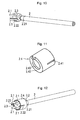
- FIG. 4 is a support bracket 2.2, which is made in the illustrated embodiment of a tin-coated bronze material, shown enlarged. Accordingly, the support bracket 2.2 comprises a sleeve-like fastener 2.21 and a fork 2.22.
- the end of the cable 2 is first freed from the jacket 2.5, so that there the inner wires 2.1 are exposed.
- the cable 2 is inserted into the support clamp 2.2, in particular the fastening element 2.21, until the fastening element 2.21 encloses the jacket 2.5.
- the Support clamp 2.2 manually or automatically relative to the wires 2.1 rotated about the longitudinal axis A until a predetermined orientation or angular position of the wires 2.1 is reached relative to the support bracket 2.2 (for example, with the aid of the optical coding of the wires 2.1).
- the support bracket 2.2 in particular the fastener 2.21 is pressed or crimped to the jacket 2.5, so that the support bracket 2.2 is mechanically fixed to the jacket 2.5. Accordingly, the support bracket 2.2 can be moved relative to the wires 2.1 neither axially nor rotated.
- the FIG. 5 shows the cable 2 with the attached to the jacket 2.5 support bracket 2.2.
- the cores 2.1 are expanded radially outward, or bent, so that the ends of the cores are oriented along a direction 2.1 having a radial direction component ( Figure 6).
- FIG. 7 is a body 2.3 shown, which is made in the illustrated embodiment of electrically insulating material, preferably made of plastic by an injection molding process.
- This body 2.3 has first recesses 2.31 and a second recess 2.32.
- the first recesses 2.31 each have an undercut, so that the respective first recess 2.31 is slightly reduced or narrowed radially on the outside compared to a region lying radially further inwards.
- the body 2.3 is pushed parallel to the longitudinal axis A until the fork 2.22 of the support clamp 2.2 is inserted into the second recess 2.32 (see FIGS. 8 and 9 ).
- the wires 2.1 pressed into the parallel to the longitudinal direction A first recesses 2.31, wherein the wires 2.1 engage in the body 2.3 by the undercuts of the first recesses 2.31, so that elastic restoring forces of the wires 2.1 are intercepted and the wires 2.1 are held parallel to the longitudinal direction A in each case.
- the course of the wires 2.1 is accordingly deflected by the body 2.3 such that the ends of the wires 2.1 are positioned according to a predetermined pattern.
- the ends of the fork 2.22 run parallel to the ends of the wires 2.1 on the body 2.3 over.
- a sleeve 2.4 which has two axially extending slots 2.41, and a radially inwardly projecting bottom 2.42, which has a central bore 2.43.
- the remote from the support clamp 2.2 end of the cable 2 is threaded and the sleeve 2.4 moves parallel to the longitudinal axis A in the direction of the support bracket 2.2.
- the fork 2.22 is finally in the slots 2.41, as for example in the Figures 12 and 13 is shown.
- the sleeve 2.4 is mounted with respect to the support bracket 2.2 or with respect to the wires 2.1 against rotation.
- an interference fit is achieved, so that the sleeve 2.4 is secured against axial slipping relative to the support bracket 2.2.
- an encapsulation with plastic around the support bracket 2.2 and the sleeve 2.4 so that the encapsulation not only acts sealingly, but can also absorb mechanical forces.
- the mounted sleeve 2.4 can be ensured that the wires 2.1 remain in the predetermined by the body 2.3 position and in particular can not escape radially from the first recesses 2.31.
- FIG. 14 shows the cable 2 after this step.
- first holes 1.1 and two second holes are made in the printed circuit board 1 1.2 introduced according to a predetermined pattern, all holes 1.1, 1.2 penetrate the circuit board 1.
- the centers of the first holes 1.1 span a surface Q in the form of a square.
- the two second bores 1.2 lie outside the surface Q spanned by the first bores 1.1.
- the first and second bores 1.1, 1.2 are metallized and printed conductors are applied to the printed circuit board 1.
- the prepared circuit board 1 is now assembled with the cable 2 in such a way that the four conductors 2.12 penetrate the four first holes 1.1 of the circuit board 1. Furthermore, the ends of the fork 2.22 of the support bracket 2.2 are added in the two second holes 1.2. The longitudinal axis A of the end of the cable 2 is oriented orthogonal to the plane of the circuit board 1. In this position, now the ends of the fork 2.22 and the conductor 2.12 are soldered to the circuit board 1. This creates an electronic assembly as in the FIGS. 15 and 16 is shown with plated-through conductors 2.12.
- a transmission of signals between the coupling part 1.3 and the wires 2.1 is now possible via the conductor tracks of the printed circuit board 1.
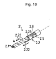
- FIG. 18 serves to explain a second embodiment.
- a shielded cable 2 ' is used, which differs from the cable 2 of the first embodiment in particular in that between the sheath 2.5 and the wires 2.1, a screen 2.6 is arranged.
- the cable 2 ' which is stripped off at the end, is introduced into the fastening element 2.21 until the fastening element 2.21 surrounds the shield 2.6.
- the support bracket 2.2 is rotated relative to the screen 2.6 about the longitudinal axis A, so that a predetermined orientation or angular position of the wires 2.1 is achieved relative to the support bracket 2.2.
- the fastening element 2.21 is then pressed or crimped around the screen 2.6, so that the support bracket 2.2 is electrically contacted with the screen 2.6 and mechanically firmly connected. Accordingly, the support bracket 2.2 can be moved relative to the wires 2.1 neither axially nor rotated.
- the assembly of the electronic assembly is analogous to that of the first embodiment.
- the electrical potential of the screen 2.6 can be transferred to the circuit board 1.
- the sleeve 2.4 may be made of metal or with a metal layer, so that an optimized shielding or EMC tightness can be achieved at this point.
- the shielded cable 2 ' is used for example in vehicles for the transmission of RF signals (high-frequency signals).
Landscapes
- Engineering & Computer Science (AREA)
- Mechanical Engineering (AREA)
- Insertion, Bundling And Securing Of Wires For Electric Apparatuses (AREA)
- Structures For Mounting Electric Components On Printed Circuit Boards (AREA)
- Details Of Resistors (AREA)
- Shielding Devices Or Components To Electric Or Magnetic Fields (AREA)
Priority Applications (5)
| Application Number | Priority Date | Filing Date | Title |
|---|---|---|---|
| EP14003043.8A EP2993736B1 (fr) | 2014-09-03 | 2014-09-03 | Composant électronique |
| DE102015210121.5A DE102015210121A1 (de) | 2014-09-03 | 2015-06-02 | Elektronische Baueinheit |
| MX2015008713A MX348012B (es) | 2014-09-03 | 2015-07-03 | Modulo electronico. |
| CN201510543760.1A CN105390837B (zh) | 2014-09-03 | 2015-08-28 | 电子结构单元 |
| US14/842,846 US9722333B2 (en) | 2014-09-03 | 2015-09-02 | Electronic component |
Applications Claiming Priority (1)
| Application Number | Priority Date | Filing Date | Title |
|---|---|---|---|
| EP14003043.8A EP2993736B1 (fr) | 2014-09-03 | 2014-09-03 | Composant électronique |
Publications (2)
| Publication Number | Publication Date |
|---|---|
| EP2993736A1 true EP2993736A1 (fr) | 2016-03-09 |
| EP2993736B1 EP2993736B1 (fr) | 2016-11-16 |
Family
ID=51492151
Family Applications (1)
| Application Number | Title | Priority Date | Filing Date |
|---|---|---|---|
| EP14003043.8A Active EP2993736B1 (fr) | 2014-09-03 | 2014-09-03 | Composant électronique |
Country Status (5)
| Country | Link |
|---|---|
| US (1) | US9722333B2 (fr) |
| EP (1) | EP2993736B1 (fr) |
| CN (1) | CN105390837B (fr) |
| DE (1) | DE102015210121A1 (fr) |
| MX (1) | MX348012B (fr) |
Cited By (1)
| Publication number | Priority date | Publication date | Assignee | Title |
|---|---|---|---|---|
| EP3618202A4 (fr) * | 2017-10-11 | 2020-04-29 | Guangdong Gopod Group Co., Ltd. | Convertisseur de connecteur |
Families Citing this family (3)
| Publication number | Priority date | Publication date | Assignee | Title |
|---|---|---|---|---|
| CN206698545U (zh) * | 2017-03-31 | 2017-12-01 | 泰科电子(上海)有限公司 | 电子元件支撑架、电子元件组件及电器组件 |
| TWI635679B (zh) * | 2017-09-07 | 2018-09-11 | 群光電子股份有限公司 | 插拔式裝置及其結構強化模組 |
| CN114696124A (zh) * | 2020-12-31 | 2022-07-01 | 安费诺电子装配(厦门)有限公司 | 一种线缆和电路板连接结构、组装方法及连接器 |
Citations (6)
| Publication number | Priority date | Publication date | Assignee | Title |
|---|---|---|---|---|
| US5806179A (en) | 1996-02-20 | 1998-09-15 | Alps Electric (Usa), Inc. | Method for connecting a cable to a printed circuit board |
| US20060234556A1 (en) * | 2005-04-19 | 2006-10-19 | Hon Hai Precision Ind. Co., Ltd. | Connector assembly |
| FR2923672A1 (fr) * | 2007-11-14 | 2009-05-15 | Thierry Gerard Francois Pont | Dispositif pour realiser des cablages de systemes complexes sans soudure dans le domaine de l'electronique pouvant etre embarques et permettant a volonte le de-cablage et le re-cablage. |
| US20090301761A1 (en) * | 2008-06-09 | 2009-12-10 | Hon Hai Precision Ind. Co., Ltd. | Cable assembly having connector with interior printed circuit board facilitating termination |
| US20120149238A1 (en) * | 2009-09-17 | 2012-06-14 | Olympus Corporation | Mounting assembly and cable assembly |
| WO2013132283A1 (fr) * | 2012-03-07 | 2013-09-12 | Aktiebolaget Skf | Unité de capteur et ensemble palier comprenant une telle unité de capteur |
Family Cites Families (12)
| Publication number | Priority date | Publication date | Assignee | Title |
|---|---|---|---|---|
| US5281762A (en) * | 1992-06-19 | 1994-01-25 | The Whitaker Corporation | Multi-conductor cable grounding connection and method therefor |
| US7214880B2 (en) * | 2002-09-24 | 2007-05-08 | Adc Incorporated | Communication wire |
| US20050263316A1 (en) * | 2004-05-28 | 2005-12-01 | Toshio Matsumoto | Anti-crosstalk cabling method, anti-crosstalk member and anti-crosstalk device for telecommunication cable |
| DE102004058195A1 (de) * | 2004-12-02 | 2006-06-08 | Patent-Treuhand-Gesellschaft für elektrische Glühlampen mbH | Leitungshalter |
| CN101098061A (zh) * | 2006-06-27 | 2008-01-02 | 富士康(昆山)电脑接插件有限公司 | 线缆连接器组件 |
| US7540773B2 (en) * | 2007-06-08 | 2009-06-02 | Hon Hai Precision Ind. Co., Ltd. | Connector assembly with improved strain relief structure |
| CN201149910Y (zh) * | 2008-01-25 | 2008-11-12 | 林乐贤 | 电连接器的改良结构 |
| TW201000602A (en) | 2008-06-30 | 2010-01-01 | Paragon Technologies Co Ltd | Organic membrane for transmitting optical spectrum and LED chip package module |
| JP5589778B2 (ja) * | 2010-11-05 | 2014-09-17 | 日立金属株式会社 | 差動信号伝送用ケーブルと回路基板の接続構造及び接続方法 |
| JP5720362B2 (ja) * | 2011-03-28 | 2015-05-20 | 住友電装株式会社 | 仕切り付きシールドパイプ |
| CN102811585A (zh) * | 2011-06-02 | 2012-12-05 | 鸿富锦精密工业(深圳)有限公司 | 电子装置 |
| CN103247916A (zh) * | 2012-02-03 | 2013-08-14 | 富士康(昆山)电脑接插件有限公司 | 线缆连接器组件 |
-
2014
- 2014-09-03 EP EP14003043.8A patent/EP2993736B1/fr active Active
-
2015
- 2015-06-02 DE DE102015210121.5A patent/DE102015210121A1/de not_active Withdrawn
- 2015-07-03 MX MX2015008713A patent/MX348012B/es active IP Right Grant
- 2015-08-28 CN CN201510543760.1A patent/CN105390837B/zh active Active
- 2015-09-02 US US14/842,846 patent/US9722333B2/en active Active
Patent Citations (6)
| Publication number | Priority date | Publication date | Assignee | Title |
|---|---|---|---|---|
| US5806179A (en) | 1996-02-20 | 1998-09-15 | Alps Electric (Usa), Inc. | Method for connecting a cable to a printed circuit board |
| US20060234556A1 (en) * | 2005-04-19 | 2006-10-19 | Hon Hai Precision Ind. Co., Ltd. | Connector assembly |
| FR2923672A1 (fr) * | 2007-11-14 | 2009-05-15 | Thierry Gerard Francois Pont | Dispositif pour realiser des cablages de systemes complexes sans soudure dans le domaine de l'electronique pouvant etre embarques et permettant a volonte le de-cablage et le re-cablage. |
| US20090301761A1 (en) * | 2008-06-09 | 2009-12-10 | Hon Hai Precision Ind. Co., Ltd. | Cable assembly having connector with interior printed circuit board facilitating termination |
| US20120149238A1 (en) * | 2009-09-17 | 2012-06-14 | Olympus Corporation | Mounting assembly and cable assembly |
| WO2013132283A1 (fr) * | 2012-03-07 | 2013-09-12 | Aktiebolaget Skf | Unité de capteur et ensemble palier comprenant une telle unité de capteur |
Cited By (1)
| Publication number | Priority date | Publication date | Assignee | Title |
|---|---|---|---|---|
| EP3618202A4 (fr) * | 2017-10-11 | 2020-04-29 | Guangdong Gopod Group Co., Ltd. | Convertisseur de connecteur |
Also Published As
| Publication number | Publication date |
|---|---|
| EP2993736B1 (fr) | 2016-11-16 |
| MX348012B (es) | 2017-05-23 |
| US9722333B2 (en) | 2017-08-01 |
| CN105390837A (zh) | 2016-03-09 |
| US20160064838A1 (en) | 2016-03-03 |
| CN105390837B (zh) | 2018-09-25 |
| DE102015210121A1 (de) | 2016-03-03 |
| MX2015008713A (es) | 2016-03-02 |
Similar Documents
| Publication | Publication Date | Title |
|---|---|---|
| DE102010017265B4 (de) | Kabelanschlusseinrichtung und Verfahren zum Anschließen eines Kabels an eine Kabelanschlusseinrichtung | |
| EP3163690B1 (fr) | Connecteur électrique coaxial comprenant une cage ressort sur le côté raccordement | |
| DE102008006340A1 (de) | Steckverbindungsanordnung mit aufgeformtem abgeschirmtem Gehäuse | |
| EP2993736B1 (fr) | Composant électronique | |
| EP2425494B1 (fr) | Dispositif de raccordement de câbles | |
| EP3161908B1 (fr) | Élément de connexion de câble | |
| WO2010112518A1 (fr) | Connecteur à fiches destiné à être connecté à un câble coaxial | |
| EP1129509B1 (fr) | Dispositif de raccordement | |
| DE102008019165A1 (de) | Kabelverschraubung, insbesondere für ein Abschirm- oder Erdungskabel | |
| EP3327875B1 (fr) | Connecteur électrique pour un câble électrique multi-fils | |
| DE102009039087A1 (de) | Verbindungsanordnung für elektrische Baugruppen | |
| DE202013010951U1 (de) | Baugruppe zur Leiterplattenbestückung | |
| EP1467441A2 (fr) | Connecteur pour un branchement rapide à technique de pince de serrage | |
| DE102008054585B4 (de) | Winkelsteckverbindung für geschirmte Kabel | |
| EP2543116B1 (fr) | Pont enfichable | |
| EP3327869B1 (fr) | Connecteur électrique pour un câble électrique multi-fils | |
| EP1313171B1 (fr) | Ensemble pour la connexion d'un connecteur électrique à un câble électrique blindé | |
| DE19948037B4 (de) | Elektrisches Steckverbindungselement und -system | |
| DE202013010545U1 (de) | Elektrisches Kontaktelement | |
| DE19525801C2 (de) | Vorrichtung zum elektrisch leitenden Verbinden von zwei elektrischen Leitungen | |
| DE102021110423A1 (de) | Hochfrequenz-steckverbindung | |
| EP1632009B1 (fr) | Element de contact et chambre de conduction complementaire pour un connecteur male ou femelle utilise en technique de raccordement autodenudant | |
| DE102019132495A1 (de) | Abschirmungsanordnung und Verfahren zur Montage einer Abschirmungsanordnung | |
| EP1149436A1 (fr) | Unite enfichable coudee coaxiale hf | |
| DE102016122396B3 (de) | Elektrische Steckverbindung mit einem elektrischen Stecker |
Legal Events
| Date | Code | Title | Description |
|---|---|---|---|
| PUAI | Public reference made under article 153(3) epc to a published international application that has entered the european phase |
Free format text: ORIGINAL CODE: 0009012 |
|
| 17P | Request for examination filed |
Effective date: 20140903 |
|
| AK | Designated contracting states |
Kind code of ref document: A1 Designated state(s): AL AT BE BG CH CY CZ DE DK EE ES FI FR GB GR HR HU IE IS IT LI LT LU LV MC MK MT NL NO PL PT RO RS SE SI SK SM TR |
|
| AX | Request for extension of the european patent |
Extension state: BA ME |
|
| GRAP | Despatch of communication of intention to grant a patent |
Free format text: ORIGINAL CODE: EPIDOSNIGR1 |
|
| RIC1 | Information provided on ipc code assigned before grant |
Ipc: H01R 12/53 20110101ALI20160804BHEP Ipc: H05K 3/32 20060101ALI20160804BHEP Ipc: H01R 9/03 20060101AFI20160804BHEP Ipc: H05K 3/34 20060101ALN20160804BHEP Ipc: H01R 12/58 20110101ALI20160804BHEP |
|
| INTG | Intention to grant announced |
Effective date: 20160824 |
|
| GRAS | Grant fee paid |
Free format text: ORIGINAL CODE: EPIDOSNIGR3 |
|
| GRAA | (expected) grant |
Free format text: ORIGINAL CODE: 0009210 |
|
| RBV | Designated contracting states (corrected) |
Designated state(s): AL AT BE BG CH CY CZ DE DK EE ES FI FR GB GR HR HU IE IS IT LI LT LU LV MC MK MT NL NO PL PT RO RS SE SI SK SM TR |
|
| AK | Designated contracting states |
Kind code of ref document: B1 Designated state(s): AL AT BE BG CH CY CZ DE DK EE ES FI FR GB GR HR HU IE IS IT LI LT LU LV MC MK MT NL NO PL PT RO RS SE SI SK SM TR |
|
| REG | Reference to a national code |
Ref country code: GB Ref legal event code: FG4D Free format text: NOT ENGLISH |
|
| REG | Reference to a national code |
Ref country code: CH Ref legal event code: EP |
|
| REG | Reference to a national code |
Ref country code: IE Ref legal event code: FG4D Free format text: LANGUAGE OF EP DOCUMENT: GERMAN |
|
| REG | Reference to a national code |
Ref country code: AT Ref legal event code: REF Ref document number: 846698 Country of ref document: AT Kind code of ref document: T Effective date: 20161215 |
|
| REG | Reference to a national code |
Ref country code: DE Ref legal event code: R096 Ref document number: 502014001938 Country of ref document: DE |
|
| PG25 | Lapsed in a contracting state [announced via postgrant information from national office to epo] |
Ref country code: LV Free format text: LAPSE BECAUSE OF FAILURE TO SUBMIT A TRANSLATION OF THE DESCRIPTION OR TO PAY THE FEE WITHIN THE PRESCRIBED TIME-LIMIT Effective date: 20161116 |
|
| REG | Reference to a national code |
Ref country code: NL Ref legal event code: MP Effective date: 20161116 |
|
| REG | Reference to a national code |
Ref country code: LT Ref legal event code: MG4D |
|
| PG25 | Lapsed in a contracting state [announced via postgrant information from national office to epo] |
Ref country code: LT Free format text: LAPSE BECAUSE OF FAILURE TO SUBMIT A TRANSLATION OF THE DESCRIPTION OR TO PAY THE FEE WITHIN THE PRESCRIBED TIME-LIMIT Effective date: 20161116 Ref country code: NO Free format text: LAPSE BECAUSE OF FAILURE TO SUBMIT A TRANSLATION OF THE DESCRIPTION OR TO PAY THE FEE WITHIN THE PRESCRIBED TIME-LIMIT Effective date: 20170216 Ref country code: GR Free format text: LAPSE BECAUSE OF FAILURE TO SUBMIT A TRANSLATION OF THE DESCRIPTION OR TO PAY THE FEE WITHIN THE PRESCRIBED TIME-LIMIT Effective date: 20170217 Ref country code: SE Free format text: LAPSE BECAUSE OF FAILURE TO SUBMIT A TRANSLATION OF THE DESCRIPTION OR TO PAY THE FEE WITHIN THE PRESCRIBED TIME-LIMIT Effective date: 20161116 Ref country code: NL Free format text: LAPSE BECAUSE OF FAILURE TO SUBMIT A TRANSLATION OF THE DESCRIPTION OR TO PAY THE FEE WITHIN THE PRESCRIBED TIME-LIMIT Effective date: 20161116 |
|
| PG25 | Lapsed in a contracting state [announced via postgrant information from national office to epo] |
Ref country code: ES Free format text: LAPSE BECAUSE OF FAILURE TO SUBMIT A TRANSLATION OF THE DESCRIPTION OR TO PAY THE FEE WITHIN THE PRESCRIBED TIME-LIMIT Effective date: 20161116 Ref country code: HR Free format text: LAPSE BECAUSE OF FAILURE TO SUBMIT A TRANSLATION OF THE DESCRIPTION OR TO PAY THE FEE WITHIN THE PRESCRIBED TIME-LIMIT Effective date: 20161116 Ref country code: PL Free format text: LAPSE BECAUSE OF FAILURE TO SUBMIT A TRANSLATION OF THE DESCRIPTION OR TO PAY THE FEE WITHIN THE PRESCRIBED TIME-LIMIT Effective date: 20161116 Ref country code: PT Free format text: LAPSE BECAUSE OF FAILURE TO SUBMIT A TRANSLATION OF THE DESCRIPTION OR TO PAY THE FEE WITHIN THE PRESCRIBED TIME-LIMIT Effective date: 20170316 Ref country code: FI Free format text: LAPSE BECAUSE OF FAILURE TO SUBMIT A TRANSLATION OF THE DESCRIPTION OR TO PAY THE FEE WITHIN THE PRESCRIBED TIME-LIMIT Effective date: 20161116 Ref country code: RS Free format text: LAPSE BECAUSE OF FAILURE TO SUBMIT A TRANSLATION OF THE DESCRIPTION OR TO PAY THE FEE WITHIN THE PRESCRIBED TIME-LIMIT Effective date: 20161116 |
|
| PG25 | Lapsed in a contracting state [announced via postgrant information from national office to epo] |
Ref country code: EE Free format text: LAPSE BECAUSE OF FAILURE TO SUBMIT A TRANSLATION OF THE DESCRIPTION OR TO PAY THE FEE WITHIN THE PRESCRIBED TIME-LIMIT Effective date: 20161116 Ref country code: SK Free format text: LAPSE BECAUSE OF FAILURE TO SUBMIT A TRANSLATION OF THE DESCRIPTION OR TO PAY THE FEE WITHIN THE PRESCRIBED TIME-LIMIT Effective date: 20161116 Ref country code: RO Free format text: LAPSE BECAUSE OF FAILURE TO SUBMIT A TRANSLATION OF THE DESCRIPTION OR TO PAY THE FEE WITHIN THE PRESCRIBED TIME-LIMIT Effective date: 20161116 Ref country code: DK Free format text: LAPSE BECAUSE OF FAILURE TO SUBMIT A TRANSLATION OF THE DESCRIPTION OR TO PAY THE FEE WITHIN THE PRESCRIBED TIME-LIMIT Effective date: 20161116 |
|
| REG | Reference to a national code |
Ref country code: DE Ref legal event code: R097 Ref document number: 502014001938 Country of ref document: DE |
|
| PG25 | Lapsed in a contracting state [announced via postgrant information from national office to epo] |
Ref country code: BG Free format text: LAPSE BECAUSE OF FAILURE TO SUBMIT A TRANSLATION OF THE DESCRIPTION OR TO PAY THE FEE WITHIN THE PRESCRIBED TIME-LIMIT Effective date: 20170216 Ref country code: SM Free format text: LAPSE BECAUSE OF FAILURE TO SUBMIT A TRANSLATION OF THE DESCRIPTION OR TO PAY THE FEE WITHIN THE PRESCRIBED TIME-LIMIT Effective date: 20161116 |
|
| PLBE | No opposition filed within time limit |
Free format text: ORIGINAL CODE: 0009261 |
|
| STAA | Information on the status of an ep patent application or granted ep patent |
Free format text: STATUS: NO OPPOSITION FILED WITHIN TIME LIMIT |
|
| REG | Reference to a national code |
Ref country code: FR Ref legal event code: PLFP Year of fee payment: 4 |
|
| 26N | No opposition filed |
Effective date: 20170817 |
|
| PG25 | Lapsed in a contracting state [announced via postgrant information from national office to epo] |
Ref country code: SI Free format text: LAPSE BECAUSE OF FAILURE TO SUBMIT A TRANSLATION OF THE DESCRIPTION OR TO PAY THE FEE WITHIN THE PRESCRIBED TIME-LIMIT Effective date: 20161116 |
|
| REG | Reference to a national code |
Ref country code: CH Ref legal event code: PL |
|
| PG25 | Lapsed in a contracting state [announced via postgrant information from national office to epo] |
Ref country code: MC Free format text: LAPSE BECAUSE OF FAILURE TO SUBMIT A TRANSLATION OF THE DESCRIPTION OR TO PAY THE FEE WITHIN THE PRESCRIBED TIME-LIMIT Effective date: 20161116 |
|
| REG | Reference to a national code |
Ref country code: IE Ref legal event code: MM4A |
|
| REG | Reference to a national code |
Ref country code: BE Ref legal event code: MM Effective date: 20170930 |
|
| PG25 | Lapsed in a contracting state [announced via postgrant information from national office to epo] |
Ref country code: LU Free format text: LAPSE BECAUSE OF NON-PAYMENT OF DUE FEES Effective date: 20170903 |
|
| PG25 | Lapsed in a contracting state [announced via postgrant information from national office to epo] |
Ref country code: CH Free format text: LAPSE BECAUSE OF NON-PAYMENT OF DUE FEES Effective date: 20170930 Ref country code: LI Free format text: LAPSE BECAUSE OF NON-PAYMENT OF DUE FEES Effective date: 20170930 Ref country code: IE Free format text: LAPSE BECAUSE OF NON-PAYMENT OF DUE FEES Effective date: 20170903 |
|
| PG25 | Lapsed in a contracting state [announced via postgrant information from national office to epo] |
Ref country code: BE Free format text: LAPSE BECAUSE OF NON-PAYMENT OF DUE FEES Effective date: 20170930 |
|
| REG | Reference to a national code |
Ref country code: FR Ref legal event code: PLFP Year of fee payment: 5 |
|
| PG25 | Lapsed in a contracting state [announced via postgrant information from national office to epo] |
Ref country code: MT Free format text: LAPSE BECAUSE OF FAILURE TO SUBMIT A TRANSLATION OF THE DESCRIPTION OR TO PAY THE FEE WITHIN THE PRESCRIBED TIME-LIMIT Effective date: 20161116 |
|
| PG25 | Lapsed in a contracting state [announced via postgrant information from national office to epo] |
Ref country code: HU Free format text: LAPSE BECAUSE OF FAILURE TO SUBMIT A TRANSLATION OF THE DESCRIPTION OR TO PAY THE FEE WITHIN THE PRESCRIBED TIME-LIMIT; INVALID AB INITIO Effective date: 20140903 |
|
| PG25 | Lapsed in a contracting state [announced via postgrant information from national office to epo] |
Ref country code: CY Free format text: LAPSE BECAUSE OF FAILURE TO SUBMIT A TRANSLATION OF THE DESCRIPTION OR TO PAY THE FEE WITHIN THE PRESCRIBED TIME-LIMIT Effective date: 20161116 |
|
| PG25 | Lapsed in a contracting state [announced via postgrant information from national office to epo] |
Ref country code: MK Free format text: LAPSE BECAUSE OF FAILURE TO SUBMIT A TRANSLATION OF THE DESCRIPTION OR TO PAY THE FEE WITHIN THE PRESCRIBED TIME-LIMIT Effective date: 20161116 |
|
| PG25 | Lapsed in a contracting state [announced via postgrant information from national office to epo] |
Ref country code: TR Free format text: LAPSE BECAUSE OF FAILURE TO SUBMIT A TRANSLATION OF THE DESCRIPTION OR TO PAY THE FEE WITHIN THE PRESCRIBED TIME-LIMIT Effective date: 20161116 |
|
| PG25 | Lapsed in a contracting state [announced via postgrant information from national office to epo] |
Ref country code: AL Free format text: LAPSE BECAUSE OF FAILURE TO SUBMIT A TRANSLATION OF THE DESCRIPTION OR TO PAY THE FEE WITHIN THE PRESCRIBED TIME-LIMIT Effective date: 20161116 Ref country code: IS Free format text: LAPSE BECAUSE OF FAILURE TO SUBMIT A TRANSLATION OF THE DESCRIPTION OR TO PAY THE FEE WITHIN THE PRESCRIBED TIME-LIMIT Effective date: 20170316 |
|
| REG | Reference to a national code |
Ref country code: AT Ref legal event code: MM01 Ref document number: 846698 Country of ref document: AT Kind code of ref document: T Effective date: 20190903 |
|
| PG25 | Lapsed in a contracting state [announced via postgrant information from national office to epo] |
Ref country code: AT Free format text: LAPSE BECAUSE OF NON-PAYMENT OF DUE FEES Effective date: 20190903 |
|
| PGFP | Annual fee paid to national office [announced via postgrant information from national office to epo] |
Ref country code: GB Payment date: 20230920 Year of fee payment: 10 Ref country code: CZ Payment date: 20230828 Year of fee payment: 10 |
|
| PGFP | Annual fee paid to national office [announced via postgrant information from national office to epo] |
Ref country code: FR Payment date: 20230928 Year of fee payment: 10 Ref country code: DE Payment date: 20230920 Year of fee payment: 10 |
|
| PGFP | Annual fee paid to national office [announced via postgrant information from national office to epo] |
Ref country code: IT Payment date: 20230927 Year of fee payment: 10 |