EP2993398B1 - Flue-gas treatment apparatus and its method of operation - Google Patents
Flue-gas treatment apparatus and its method of operation Download PDFInfo
- Publication number
- EP2993398B1 EP2993398B1 EP15183249.0A EP15183249A EP2993398B1 EP 2993398 B1 EP2993398 B1 EP 2993398B1 EP 15183249 A EP15183249 A EP 15183249A EP 2993398 B1 EP2993398 B1 EP 2993398B1
- Authority
- EP
- European Patent Office
- Prior art keywords
- heating
- medium
- flue
- gas
- temperature
- Prior art date
- Legal status (The legal status is an assumption and is not a legal conclusion. Google has not performed a legal analysis and makes no representation as to the accuracy of the status listed.)
- Active
Links
- UGFAIRIUMAVXCW-UHFFFAOYSA-N Carbon monoxide Chemical compound [O+]#[C-] UGFAIRIUMAVXCW-UHFFFAOYSA-N 0.000 title claims description 234
- 239000003546 flue gas Substances 0.000 title claims description 234
- 238000000034 method Methods 0.000 title claims description 19
- 238000011084 recovery Methods 0.000 claims description 158
- 238000010438 heat treatment Methods 0.000 claims description 122
- 239000007789 gas Substances 0.000 claims description 27
- 238000002485 combustion reaction Methods 0.000 claims description 19
- 238000011144 upstream manufacturing Methods 0.000 claims description 6
- 238000006477 desulfuration reaction Methods 0.000 claims description 3
- 230000023556 desulfurization Effects 0.000 claims description 3
- 239000000428 dust Substances 0.000 claims description 3
- 239000012716 precipitator Substances 0.000 claims description 3
- 229910052815 sulfur oxide Inorganic materials 0.000 claims description 3
- XTQHKBHJIVJGKJ-UHFFFAOYSA-N sulfur monoxide Chemical class S=O XTQHKBHJIVJGKJ-UHFFFAOYSA-N 0.000 claims description 2
- 238000010586 diagram Methods 0.000 description 8
- -1 90°C) Chemical compound 0.000 description 6
- 238000009833 condensation Methods 0.000 description 6
- 230000005494 condensation Effects 0.000 description 6
- XLYOFNOQVPJJNP-UHFFFAOYSA-N water Substances O XLYOFNOQVPJJNP-UHFFFAOYSA-N 0.000 description 5
- 239000012717 electrostatic precipitator Substances 0.000 description 4
- 238000012546 transfer Methods 0.000 description 4
- 238000001816 cooling Methods 0.000 description 3
- 230000000694 effects Effects 0.000 description 3
- MWUXSHHQAYIFBG-UHFFFAOYSA-N nitrogen oxide Inorganic materials O=[N] MWUXSHHQAYIFBG-UHFFFAOYSA-N 0.000 description 3
- 238000005259 measurement Methods 0.000 description 2
- 238000011017 operating method Methods 0.000 description 2
- 230000001687 destabilization Effects 0.000 description 1
- 239000000446 fuel Substances 0.000 description 1
- 230000004048 modification Effects 0.000 description 1
- 238000012986 modification Methods 0.000 description 1
- 230000000630 rising effect Effects 0.000 description 1
- 239000007787 solid Substances 0.000 description 1
Images


Classifications
-
- F—MECHANICAL ENGINEERING; LIGHTING; HEATING; WEAPONS; BLASTING
- F23—COMBUSTION APPARATUS; COMBUSTION PROCESSES
- F23J—REMOVAL OR TREATMENT OF COMBUSTION PRODUCTS OR COMBUSTION RESIDUES; FLUES
- F23J15/00—Arrangements of devices for treating smoke or fumes
- F23J15/02—Arrangements of devices for treating smoke or fumes of purifiers, e.g. for removing noxious material
-
- F—MECHANICAL ENGINEERING; LIGHTING; HEATING; WEAPONS; BLASTING
- F23—COMBUSTION APPARATUS; COMBUSTION PROCESSES
- F23J—REMOVAL OR TREATMENT OF COMBUSTION PRODUCTS OR COMBUSTION RESIDUES; FLUES
- F23J15/00—Arrangements of devices for treating smoke or fumes
-
- F—MECHANICAL ENGINEERING; LIGHTING; HEATING; WEAPONS; BLASTING
- F23—COMBUSTION APPARATUS; COMBUSTION PROCESSES
- F23J—REMOVAL OR TREATMENT OF COMBUSTION PRODUCTS OR COMBUSTION RESIDUES; FLUES
- F23J15/00—Arrangements of devices for treating smoke or fumes
- F23J15/006—Layout of treatment plant
-
- F—MECHANICAL ENGINEERING; LIGHTING; HEATING; WEAPONS; BLASTING
- F23—COMBUSTION APPARATUS; COMBUSTION PROCESSES
- F23J—REMOVAL OR TREATMENT OF COMBUSTION PRODUCTS OR COMBUSTION RESIDUES; FLUES
- F23J15/00—Arrangements of devices for treating smoke or fumes
- F23J15/06—Arrangements of devices for treating smoke or fumes of coolers
-
- F—MECHANICAL ENGINEERING; LIGHTING; HEATING; WEAPONS; BLASTING
- F23—COMBUSTION APPARATUS; COMBUSTION PROCESSES
- F23J—REMOVAL OR TREATMENT OF COMBUSTION PRODUCTS OR COMBUSTION RESIDUES; FLUES
- F23J15/00—Arrangements of devices for treating smoke or fumes
- F23J15/08—Arrangements of devices for treating smoke or fumes of heaters
-
- Y—GENERAL TAGGING OF NEW TECHNOLOGICAL DEVELOPMENTS; GENERAL TAGGING OF CROSS-SECTIONAL TECHNOLOGIES SPANNING OVER SEVERAL SECTIONS OF THE IPC; TECHNICAL SUBJECTS COVERED BY FORMER USPC CROSS-REFERENCE ART COLLECTIONS [XRACs] AND DIGESTS
- Y02—TECHNOLOGIES OR APPLICATIONS FOR MITIGATION OR ADAPTATION AGAINST CLIMATE CHANGE
- Y02E—REDUCTION OF GREENHOUSE GAS [GHG] EMISSIONS, RELATED TO ENERGY GENERATION, TRANSMISSION OR DISTRIBUTION
- Y02E20/00—Combustion technologies with mitigation potential
- Y02E20/30—Technologies for a more efficient combustion or heat usage
Definitions
- the present invention relates to a flue-gas treatment apparatus for purifying a flue gas discharged from a combustion apparatus, such as a boiler, used in a thermal power system, such as a thermal power plant, and an operating method thereof.
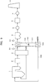
- Fig. 9 discloses a flue-gas treatment apparatus according to prior art for use in a thermal power plant as disclosed in JP 4725985 . Note that throughout the drawings, the same features are given the same reference signs.
- a flue gas discharged from a boiler 1 disposed in a thermal power plant, an exhaust-gas emission apparatus, or the like is introduced to a denitrification unit 2 so that nitrogen oxides are removed from the flue gas.
- the resulting flue gas is subjected to heat exchange with combustion air to be fed to the boiler 1 in an air preheater 3.
- the resulting flue gas is introduced into an electrostatic precipitator 4 so that dust is mostly removed from the flue gas.
- the resulting flue gas is pressurized by an induced draft fan 5 and introduced into a desulfurization unit 6 so that sulfur oxides (SOx) are removed from the flue gas.
- the resulting flue gas is pressurized by a boost-up fan 7 and discharged from a smokestack 8.
- a heat recovery unit 9 is disposed adjacent to the inlet of the electrostatic precipitator 4 in the flue-gas flow path; a feedwater line 106 for feeding water to the boiler 1 is disposed; a feedwater heater 100 is disposed in the feedwater line 106; a heating-medium circulation pipe 101 for communicating the heat recovery unit 9 and feedwater heater 100 is disposed; a heating-medium bypass pipe 102 which allows the heating medium on the inlet side of the heat recovery unit to circulate to the feedwater heater 100 while bypassing the heat recovery unit 9 is disposed in the heating-medium circulation pipe 101; and a heating-medium flow-rate control valve 103 is disposed in the heating-medium bypass pipe 102.
- a method for operating the flue-gas treatment apparatus constitute of the composition described above includes: when the temperature of the flue gas upstream side of the precipitator 4 in the flue-gas flow path is lower than the dew point of corrosive components in the flue gas, opening the heating-medium flow-rate control valve 103 to cause the heating medium to bypass the heat recovery unit 9 or to reduce the amount of the heating medium flowing into the heat recovery unit 9 so as to reduce the amount of heat exchange therein; subsequently, when the heat is recovered from the flue gas in the heat recovery unit 9 and the outlet flue-gas temperature of the heat recovery unit 9 reaches a set value or more, closing the heating-medium flow-rate control valve 103 in the heating-medium bypass pipe 102 so that the heating medium which has recovered heat from the flue gas in the heat recovery unit 9 is introduced into the feedwater heater 100 through the heating-medium circulation pipe 101; and after heating boiler feedwater, reintroducing the heating medium into the heat recovery unit
- JP 2014-9877 A1 discloses a flue gas treatment apparatus according to the preamble of claim 1 and JP H09-122438 A1 (D5).
- the conditions for a flue gas discharged from a boiler or the conditions of a heating medium used to generate power using turbines are often not as planned.
- the temperature of a heating medium water
- the flue gas must be cooled to the planned temperature (90°C or the like), since the boiler is incinerating fuel.
- flue-gas temperature at the outlet of the heat recovery unit 9 can be controlled in terms of heat calculation.
- a deviation is generated in amounts of heating medium flow into the respective heat transfer pipes of the heat recovery unit 9. This prevents uniform heat exchange in the heat recovery unit 9.
- the object of the invention of Patent Literature 4 is to control the heat in gas cooling device (4) by controlling volume of the heating-medium in the heating-medium circulation line (29) by changing the opening level of the valve (20) in the heating-medium bypass line (30).
- Patent Literature 5 The object of the invention of Patent Literature 5 is "maintain a temperature of a flue gas above dew point at an outlet of the heat recovery unit (6) during startup of a combustion apparatus such as a boiler (1).
- Patent Literature 5 discloses the method is disclosed the operation method of the combustion apparatus which is all or some of the volume of a heating medium is circulated at a re-heater unit (10) by controlling opening level of a valve (44) at bypass line (41) to decrease the volume of a heating medium circulated in a heat recovery unit (6), during startup of a combustion apparatus or immediately after igniting burners of the combustion apparatus.
- the heat recovery unit (6) is warmed by the steam heater (42) provided at a heating medium line (28) and volume of a heating medium in a heat recovery unit bypass line (30) provided in parallel to a heat conductive tube (21) in the heat recovery unit (6) is controlled until the a heating medium temperature at the outlet of the heat recovery unit (6) is higher than preset temperature (above dew point).
- Patent Literature 4 or 5 do not suggest that the heating-medium from the outlet of the gas cooling device (4) in Patent Literature 4 or the heat recovery unit (6) in Patent Literature 5 is not fed to directly by pumps (18, 27) through both of bypass lines (30, 30) to the gas cooling device (4) or the heat recovery unit (6) during startup of a combustion apparatus or immediately after igniting burners of the combustion apparatus.
- An object of the present invention is to avoid the destabilization of flue-gas temperature at the outlet of the heat recovery apparatus and the placement in a corrosive environment of the heat recovery apparatus, the wall surface of the flue-gas flow path downstream side of the heat recovery apparatus, and the devices in the downstream side of flue-gas flow path, because of instability of the supply amount and the temperature of the heating-medium caused by an effect of variation of the amount and the temperature of the flue-gas during startup or stop of the thermal power system.
- a second aspect of the present invention provides a method for operating a flue-gas treatment apparatus according to claim 2.
- a third aspect of the present invention provides a flue-gas treatment apparatus according to claim 3.
- a fourth aspect of the present invention provides a method for operating a flue-gas treatment apparatus according to claim 4.
- a fifth aspect of the present invention provides a method for operating a flue-gas treatment apparatus according to claim 5.
- the heating-medium circulation line (11) through which the heating medium is circulated and fed is disposed between the heat recovery unit (9) and heating-medium using unit (10), the first heating-medium bypass line (13) and second heating-medium bypass line (15) that allow the heating medium from the outlet of the heat recovery unit (9) to circulate to the inlet of the heat recovery unit (9) while bypassing the heating-medium using unit (10) are disposed in the heating-medium circulation line (11), and the first heating-medium flow-rate control valve (CV2) and second heating-medium flow-rate control valve (CV3) are disposed in the first heating-medium bypass line (13) and second heating-medium bypass line (15), respectively.
- the first heating-medium flow-rate control valve (CV2) and second heating-medium flow-rate control valve (CV3) are disposed in the first heating-medium bypass line (13) and second heating-medium bypass line (15), respectively.
- the flow rates of the heating-medium flowing through the heating-medium bypass lines (13, 15) can be controlled by controlling the degrees of opening of the first heating-medium flow-rate control valve (CV2) and second heating-medium flow-rate control valve (CV3).
- the heat recovery unit (9) when the heat recovery unit (9) recovers heat from a flue gas from the combustion apparatus such as the boiler (1) during the startup of a thermal power system or the like and when the temperature of the heating medium is low, it is possible to prevent the heating surface of the heat recovery unit (9) from being corroded due to condensation, as well as to stably keep the flue-gas temperature at the outlet of the heat recovery unit (9) in the planned state.
- the planned heating-medium circulation rate of the heat recovery unit (9) can be maintained owing to the first heating-medium bypass line (13) having the auxiliary pump (17) and first heating-medium flow-rate control valve (CV2) thereon, the second heating-medium bypass line (15) having the second heating-medium flow-rate control valve (CV3) thereon, which connect the heat recovery unit (9) and heating-medium using unit (10), the operation of the auxiliary pump (17), and the heating-medium flow-rate control valves (CV2, CV3).
- stable flue-gas temperature at the outlet of the heat recovery unit (9) and stable heating-medium temperature at the inlet of the heat recovery unit (9) can be achieved independently of the variations in the flow rate and temperature of the heating medium from the thermal power system. From these stability of the temperature, it is possible to avoid the heat recovery unit (9), the wall of the flue-gas flow path downstream thereof, and the units in the downstream flue-gas flow path from being placed in a corrosive environment, as well as to achieve stable start of the combustion apparatus.
- the heat recovery unit (9) for recovering heat from the flue gas from the combustion apparatus such as the boiler (1) is disposed independently; and heat recovered by the heat recovery unit (9) is used for boiler feedwater, if the flue-gas temperature measured by the first flue-gas thermometer (TE1) or second flue-gas thermometer (TE2) disposed at the inlet or outlet of the heat recovery unit (9) in the flue-gas flow path is lower than the preset temperature (the dew point of corrosive components in the flue gas; e.g., 90°C), the heating-medium circulation system between the heat recovery unit (9) and heating-medium using unit (10) is started in a state in which the heating-medium circulation system between the heat recovery unit (9) and heating-medium using unit (10) is separated.
- the preset temperature the dew point of corrosive components in the flue gas
- the heating medium warmed by the heat of the flue gas in the flue-gas flow path may be naturally convected in the system of the heat recovery unit (9) and thus the heating medium in the heat recovery unit (9) may be warmed locally and flashed (vaporized), as well as to avoid an increase in the time in which the heat recovery unit (9) and the wall of the flue-gas flow path downstream thereof, and the units in the downstream flue-gas flow path is placed in a corrosive environment.
- the heating-medium circulation system between the heat recovery unit (9) and heating-medium using unit (10) is started in a state in which the heating-medium circulation system between the heat recovery unit (9) and heating-medium using unit (10) is separated, if the flue-gas temperature measured by the second flue-gas thermometer (TE2) disposed at the outlet of the heat recovery unit (9) in the flue-gas flow path is lower than the preset temperature (the dew point of corrosive components in the flue gas; e.g., 90°C), the heating medium warmed by the heat of the flue gas at the outlet of the air preheater (3) is forcefully convected in the system of the heat recovery unit (9) during the startup of the boiler (1) or the like, during which the flue-gas temperature is low.
- the preset temperature the dew point of corrosive components in the flue gas
- Fig. 1 is a flow diagram of a flue-gas treatment system of the present embodiment.
- Fig. 2 is a diagram showing an example of a heat recovery unit (gas cooler) 9 included in the flue-gas treatment system in Fig. 1 and composed of heat transfer pipes and a heating-medium flow path system through which a heating medium is fed to the heat recovery unit 9.
- the flue-gas treatment system shown in Fig. 1 uses a heating-medium using unit 10 in place of the feedwater heater 100, which is shown in the flow diagram of the conventional flue-gas treatment system shown in Fig. 9 and which operates using the heat of a flue gas.
- the heating-medium flow path system between the heat recovery unit 9 and heating-medium using unit 10 shown in Fig. 1 differs from that in Fig. 9 only partially.
- feedwater from a feedwater source is fed through a feedwater (heating medium) pipe to the heat recovery unit 9 using a circulation pump 18 and reduces the temperature of the flue gas, and then the feedwater whose temperature has been increased is fed to the heating-medium using unit 10.
- a feedwater heating medium
- multiple heat recovery units 9 may be disposed in parallel in the flue-gas flow path.
- An inlet feedwater pipe 11a through which the heating medium is fed to the heat recovery unit 9 and an outlet feedwater pipe 11b into which the heat recovery unit 9 discharges the heating medium which has recovered heat constitute a heating-medium circulation line 11.
- a flue-gas temperature control valve CV1 and a heating-medium thermometer TE3 are disposed in the inlet feedwater pipe 11a so as to be adjacent to the inlets of the heat transfer pipes of the heat recovery unit 9.
- the flue-gas temperature control valve CV1 controls the gas temperature at the outlet of the heat recovery unit 9 in the flue-gas flow path by controlling the flow rate of the heating medium.
- the heating-medium thermometer TE3 measures the temperature of the heating medium in the inlet feedwater pipe 11a.
- a first heating-medium flowmeter FX1 is disposed in the inlet feedwater pipe 11a between the respective junctions of the inlet feedwater pipe 11a and a first heating-medium bypass line 13 and a second heating-medium bypass line 15 (to be discussed later).
- the first heating-medium flowmeter FX1 measures the flow rate of the heating medium in the inlet feedwater pipe 11a.
- the first heating-medium bypass line 13 and second heating-medium bypass line 15 connect the inlet feedwater pipe 11a and outlet feedwater pipe 11b, which are disposed between the heat recovery unit 9 and heating-medium using unit 10.
- the first heating-medium bypass line 13 connects the inlet feedwater pipe 11a and outlet feedwater pipe 11b in a position closer to the heat recovery unit 9 than to the heating-medium using unit 10.
- the second heating-medium bypass line 15 connects the inlet feedwater pipe 11a and outlet feedwater pipe 11b in a position closer to the heating-medium using unit 10 than to the heat recovery unit 9.
- An auxiliary pump 17 for feeding the heating medium from the outlet feedwater pipe 11b to the inlet feedwater pipe 11a and a first heating-medium flow-rate control valve CV2 are disposed in the first heating-medium bypass line 13.
- a second heating-medium flow-rate control valve CV3 for controlling the amount of the heating medium flowing from the inlet feedwater pipe 11a to the outlet feedwater pipe 11b while bypassing the heat recovery unit 9 and a second heating-medium flowmeter FX2 are disposed in the second heating-medium bypass line 15.
- the heat recovery unit 9 which is disposed in the flue-gas flow path of the boiler, includes an inlet flue-gas thermometer TE1 and an outlet flue-gas thermometer TE2.
- thermometers TE1, TE2, and TE3 and heating-medium flowmeters FX1 and FX2 are transmitted to a controller 20. Based on the measurement values, the controller 20 transmits operation signals to the control valves CV1, CV2, and CV3, auxiliary pump 17, and circulation pump 18.
- the auxiliary pump 17 disposed in the first heating-medium bypass line 13 feeds the heating medium from the outlet feedwater pipe 11b through the first heating-medium bypass line 13 to the inlet feedwater pipe 11a.
- the second heating-medium bypass line 15 connects an upstream portion of the inlet feedwater pipe 11a with respect to the first heating-medium bypass line 13 and a downstream portion of the outlet feedwater pipe 11b with respect thereto.
- the circulation pump 18 disposed in the inlet feedwater pipe 11a the heating medium is fed from the inlet feedwater pipe 11a through the second heating-medium bypass line 15 to the outlet feedwater pipe 11b.
- the second heating-medium bypass line 15 is provided with the second heating-medium flow-rate control valve CV3.
- the second heating-medium flow-rate control valve CV3 controls the flow rate of the heating medium using a value obtained by subtracting the amount of the heating medium used in the heat recovery unit 9 from a feed heating-medium amount request signal from a flue gas source such as the boiler 1, as a heating-medium bypass flow-rate set value in the second heating-medium bypass line 15.
- the flow rate of the heating medium in the second heating-medium bypass line 15 is controlled while measuring it using the second heating-medium flowmeter FX2.
- the second heating-medium flow-rate control valve (bypass heating-medium flow-rate control valve) CV3 is moved in a closing direction to reduce the bypass heating-medium flow rate.
- the bypass heating-medium flow-rate control valve CV3 is moved in an opening direction to increase the bypass heating-medium flow rate.
- the bypass heating-medium flow-rate control valve CV3 also detects the temperature of the heating medium flowing through the inlet feedwater pipe 11a using the heating-medium thermometer TE3 and controls the amount of the bypass heating medium, which is fed through the second heating-medium bypass line 15 to the inlet feedwater pipe 11a, so that the temperature of the heating medium becomes a preset temperature.
- the bypass heating-medium flow-rate control valve CV3 is moved in a closing direction to reduce the flow rate of the bypass heating-medium flowing through the second heating-medium bypass line 15; when the flue-gas temperature measured by the thermometer TE1 or TE2 is lower than the set temperature, the bypass heating-medium flow-rate control valve CV3 is moved in an opening direction to increase the flow rate of the bypass heating medium flowing through the second heating-medium bypass line 15.
- the opening or closing of the bypass heating-medium flow-rate control valve CV3 described above is controlled by performing PI (proportional-integral) control on the difference between the set flue-gas temperature of the heat recovery unit 9 and the actual flue-gas temperature thereof (the temperature measured by the thermometer TE1 or TE2).
- PI proportional-integral
- the temperature at the inlet of the heat recovery unit 9 in the flue-gas flow path (hereafter also simply referred to as the inlet temperature of the heat recovery unit 9) is measured by the thermometer TE1, or the temperature at the outlet of the heat recovery unit 9 in the flue-gas flow path (hereafter also simply referred to as the outlet temperature of the heat recovery unit 9) is measured by the thermometer TE2.
- the flue-gas temperature control valve CV1 in the inlet feedwater pipe 11a is kept closed, since there is no need to exchange heat between the flue gas and heating medium in the heat recovery unit 9.
- the sett temperature of the flue-gas in the flue-gas flow path in which the heat recovery unit 9 is disposed can be set voluntarily in accordance with the load of the boiler. Thus, adjustments are made to the average temperature in the region in which the heat recovery unit 9 is disposed, of the flue-gas flow path be kept at the set temperature.
- the flue-gas temperature control valve CV1 is opened with the degree of opening which is preset with respect to the flue-gas temperature at the inlet of the heat recovery unit 9 in accordance with the program setting.
- the flue-gas temperature control valve CV1 When the flue-gas temperature at the inlet of the heat recovery unit 9 is more than 90°C but the flue-gas temperature at the outlet thereof is less than 90°C (at this time, the heating medium temperature at the inlet of the heat recovery unit 9 is less than the set temperature of 72°C), the flue-gas temperature control valve CV1 is closed, and the second heating-medium flow-rate control valve CV3 in the second heating-medium bypass line 15 is fully opened in order for the outlet flue-gas temperature of the heat recovery unit 9 to be quickly increased to 90°C or more.
- the heating medium having a relatively high temperature from the outlet of the heat recovery unit 9 is passed through the first heating-medium bypass line 13 and circulated and fed to the inlet of the heat recovery unit 9.
- the first heat-medium flow-rate control valve CV2 which controls the flow rate of the heating medium in the first heating-medium bypass line 13, is closed.
- FIG. 3 a heating-medium flow-rate control process performed from when the boiler is started to when the outlet flue-gas temperature of the heat recovery unit 9 is increased to 90°C or more.
- the circulation pump 18 is started, and the bypass heating-medium flow-rate control valve (second heating-medium flow-rate control valve) CV3 in the second heating-medium bypass line 15 is fully opened.
- the bypass heating-medium flow-rate control valve (second heating-medium flow-rate control valve) CV3 in the second heating-medium bypass line 15 is fully opened.
- all feedwater (heating medium) flowing into the inlet feedwater pipe 11a flows through the second heating-medium bypass line 15 while bypassing the heat recovery unit 9.
- the heat recovery unit 9 does not have to exchange the heat of the flue gas. Accordingly, the flue-gas temperature control valve CV1 in the inlet feedwater pipe 11a is kept closed.
- the flue-gas temperature control valve CV1 When the flue-gas temperature at the inlet or the outlet of the heat recovery unit 9 (the flue-gas temperature measured by the thermometer TE1 or TE2) exceeds 90°C, the flue-gas temperature control valve CV1 is opened with a predetermined degree of opening, and the second heating-medium flow-rate control valve CV3 is moved in a closed direction. At this time, the second heating-medium flow-rate control valve CV3 is controlled in a closing direction so that part of the heating medium fed from the circulation pump 18 to the heat recovery unit 9 flows through the second heating-medium bypass line 15.
- the flue-gas temperature control valve CV1 is controlled to start to open slightly and simultaneously the second heating-medium flow-rate control valve CV3 is controlled to start to close , the degree of opening of the flue-gas temperature control valve CV1 increases as the flue-gas temperature increases, and the amount of the heating medium flowing through the second heating-medium bypass line 15 is controlled to be reduced compared to the amount of the heating medium fed from the circulation pump 18.
- the flue-gas temperature control valve CV1 is opened to a predetermined degree of opening; and when the amount of the heating medium fed from the circulation pump 18 becomes the same as the amount of the heating medium fed to the heat recovery unit 9, the second heating-medium flow-rate control valve CV3 is fully closed.
- the second heating-medium flow-rate control valve CV3 is maintained with a predetermined degree of opening so that the heating medium is circulated to the heating-medium using unit 10 through the second heating-medium bypass line 15.
- the auxiliary pump 17 disposed in the first heating-medium bypass line 13 is automatically started.
- the heating medium from the outlet of the heat recovery unit 9 can be fed to the inlet thereof through the first heating-medium bypass line 13.
- a backup auxiliary pump 17' may be disposed in a position parallel with the auxiliary pump 17.
- the degree of opening of the first heating-medium flow-rate control valve CV2 is prevented from becoming the minimum degree of opening or less.
- the first heating-medium flow-rate control valve CV2 is prevented from being completely closed.
- the first heating-medium flow-rate control valve CV2 controls the flow rate of the heating medium so that the temperature detected by the heating-medium thermometer TE3 disposed in the inlet feedwater pipe 11a becomes a predetermined temperature (e.g., 72°C). Specifically, when the temperature detected by the heating-medium thermometer TE3 falls below 72°C, part of the heating medium heated by the heat recovery unit 9 is passed through the heating-medium bypass line 13 and added to the heating medium flowing through the inlet feedwater pipe 11a by the auxiliary pump 17. Thus, the temperature of the heating medium flowing through the inlet feedwater pipe 11a is increased.
- a predetermined temperature e.g., 72°C
- the first heating-medium flow-rate control valve CV2 When the temperature measured by the thermometer TE1 or TE2 becomes higher than 90°C by a predetermined temperature (2°C), the first heating-medium flow-rate control valve CV2 is closed, and simultaneously the auxiliary pump 17 is stopped, or the heating medium is fed to a minimum flow line (not shown). Thus, the heating medium heated by the heat recovery unit 9 is fed to another heating-medium using unit 10 (not shown) without flowing through the first heating-medium bypass line 13, and heat is transferred in the other heating-medium using unit 10.
- the first heating-medium flow-rate control valve CV2 may be operated as follows.
- the heating-medium temperature detected by the heating-medium thermometer TE3 falls below 72°C
- part of the heating medium heated by the heat recovery unit 9 is passed through the first heating-medium bypass line 13 and added to the heating medium flowing through the inlet feedwater pipe 11a by the auxiliary pump 17.
- the temperature of the heating medium flowing through the inlet feedwater pipe 11a is increased, so that the temperature detected by the heating-medium thermometer TE3 exceeds 72°C.
- the operation to close the first heating-medium flow-rate control valve CV2 is started; then the auxiliary pump 17 is stopped; and then the first heating-medium flow-rate control valve CV2 is closed.
- the flue-gas temperature is the predetermined temperature or more, even if the temperature of the heating medium fed from the heating-medium circulation line 11 to the heat recovery unit 9 by the circulation pump 18 is reduced to the predetermined temperature or less, it is possible to prevent the inside of the flue-gas flow path downstream of the heat recovery unit 9 from being corroded due to condensation, as well as to stably keep high the temperature of the heating medium flowing through the heat recovery unit 9.
- the second heating-medium flow-rate control valve CV3 in the second heating-medium bypass line 15 is fully opened to circulate the heating medium through the second heating-medium bypass line 15.
- the flue-gas temperature measured by the thermometer TE1 or TE2 disposed at the inlet or outlet of the heat recovery unit 9 in the flue-gas flow path is lower than the preset temperature (e.g., 90°C)
- the flue-gas temperature control valve CV1 in the heating-medium circulation line 11 is kept closed.
- the heating medium confined within the heat recovery unit (gas cooler) 9 recovers heat from the flue gas and thus is gradually warmed.
- the heating medium may be flashed (be vaporized) and thus may cause a water hammer phenomenon, which may damage the heat transfer pipes in the heat recovery unit 9.
- the present embodiment is a configuration for stably operating a heat recovery unit (gas cooler) 9 during the startup of a boiler, without causing a water hammer phenomenon.
- this configuration is characterized in that a third heating-medium bypass line 19 is additionally disposed in the configuration shown in Fig. 2 .
- the third heating-medium bypass line 19 is disposed in parallel with a first heating-medium bypass line 13 and a second heating-medium bypass line 15 and connect an inlet feedwater pipe 11a and an outlet feedwater pipe 11b of a heat medium circulation line 11 so that the heating medium from the outlet of a heating-medium using unit 10 is returned to the inlet thereof while bypassing all of the gas cooler 9, first heating-medium bypass line 13, and second heating-medium bypass line 15.
- a first on/off valve 21 is disposed in the third heating-medium bypass line 19.
- a second on/off valve 22 is disposed in the inlet feedwater pipe 11a between the junction of the second heating-medium bypass line 15 and inlet feedwater pipe 11a and the junction of the third heating-medium bypass line 19 and inlet feedwater pipe 11a.
- a third on/off valve 23 is disposed in the outlet feedwater pipe 11b between the junction of the second heating-medium bypass line 15 and outlet feedwater pipe 11b and the junction of the third heating-medium bypass line 19 and outlet feedwater pipe 11b.
- auxiliary pumps 17 and 17' are disposed in parallel in the first heating-medium bypass line 13.
- a circulation pump 18 for circulating and feeding the heating medium to the gas cooler 9 is disposed in the inlet feedwater pipe 11a upstream of the junction of the third heating-medium bypass line 19 and inlet feedwater pipe 11a.
- a first flue-gas thermometer TE1 for measuring the temperature of the flue gas is disposed adjacent to the inlet of the gas cooler 9 in the flue-gas flow path; a second flue-gas thermometer TE2 for measuring the temperature of the flue gas is disposed adjacent to the outlet of the gas cooler 9 in the flue-gas flow path; and a heating-medium thermometer TE3 for measuring the temperature of the heating medium in the heating-medium circulation line 11 is disposed adjacent to the inlet of the gas cooler 9.
- thermometers TE1 and TE2 and heating-medium thermometer TE3 are inputted to a controller 20. Based on these pieces of information, the controller 20 outputs signals to the flue-gas temperature control valves CV1, CV2, and CV3 and on/off valves 21, 22, and 23.
- a method for operating a flue-gas treatment apparatus having the above configuration and used in a combustion apparatus including a boiler 1 during the startup of a combustion apparatus including a boiler 1 or immediately after igniting the burners of the combustion apparatus includes:
- a flue-gas treatment apparatus operating method which includes, instead of the above (b), when the flue-gas temperature measured by the first flue-gas thermometer TE1 or second flue-gas thermometer TE2 is lower than the preset temperature (the dew point of corrosive components in the flue gas; e.g., 90°C), opening the flue-gas temperature control valve CV1 and opening the second heating-medium flow-rate control valve CV3 in the second heating-medium bypass line 15 to circulate the heating medium between the second heating-medium bypass line 15 and heat recovery unit (gas cooler) 9, further opening the first heating-medium flow-rate control valve CV2 in the first heating-medium bypass line 13, and starting the auxiliary pump 17 to forcefully circulate the heating medium between the first heating-medium bypass line 13 and heat recovery unit 9.
- the preset temperature the dew point of corrosive components in the flue gas
- FIG. 6 and 7 there will be described a heating-medium flow-rate control process according to the second embodiment which is performed until the outlet flue-gas temperature of the heat recovery unit 9 becomes 90°C or more during the startup of the combustion apparatus including the boiler 1 or immediately after igniting the combustion apparatus.
- Initial control steps include fully opening the first on/off valve 21, fully closing the second on/off valve 22 and third on/off valve 23 in the heating-medium circulation line 11, and starting the circulation pump 18 so that the heating medium flowing into the outlet feedwater pipe 11b is circulated through the third heating-medium bypass line 19, heating-medium using unit 10, and inlet feedwater pipe 11a.
- Subsequent control steps include steps according to the flow of Fig. 6 and steps according to the flow of Fig. 7 .
- the control steps includes when the flue-gas temperature measured by the first flue-gas thermometer TE1 or second flue-gas thermometer TE2 disposed at the inlet or outlet of the gas cooler 9 in the flue-gas flow path is lower than or equal to the preset temperature (the dew point of corrosive components in the flue gas; e.g., 90°C), opening the flue-gas temperature control valve CV1 in the heating-medium circulation line 11 and opening the second heating-medium flow-rate control valve CV3 in the second heating-medium bypass line 15 so that the heating medium in the gas cooler 9 naturally circulates between the gas cooler 9 and second heating-medium bypass line 15.
- the preset temperature the dew point of corrosive components in the flue gas
- the control steps also include when the flue-gas temperature measured by the first flue-gas thermometer TE1 or second flue-gas thermometer TE2 at the inlet or outlet of the heat recovery unit 9 in the flue-gas flow path becomes higher than the preset temperature (e.g., 90°C), fully closing the first on/off valve 21 in the third heating-medium bypass line 19, fully opening the second on/off valve 22 and third on/off valve 23 in the heating-medium circulation line 11, opening the flue-gas temperature control valve CV1 in the heating-medium circulation line 11, and starting to close the second heat medium flow rate control valve CV3 so that the flow rates of the heating medium flowing through the heating-medium bypass lines 13 and 15 are gradually reduced.
- the preset temperature e.g. 90°C
- the control steps includes when the flue-gas temperature measured by the first flue-gas thermometer TE1 or second flue-gas thermometer TE2 at the inlet or outlet of the gas cooler 9 in the flue-gas flow path is lower than or equal to the preset temperature (the dew point of corrosive components in the flue gas; e.g., 90°C), opening the flue-gas temperature control valve CV1 in the heating-medium circulation line 11 and the second heating-medium flow-rate control valve CV3 in the second heating-medium bypass line 15 and opening the first heating-medium flow-rate control valve CV2 in the first heating-medium bypass line 13 so that the feedwater (heating medium) is circulated among the gas cooler 9, first heating-medium bypass line 13, and second heating-medium bypass line 15. Since the auxiliary pump 17 is disposed in the first heating-medium bypass line 13, the heating medium can be more smoothly circulated between the heat recovery unit 9 and heating-medium using unit 10 by starting the auxiliary pump 17.
- the preset temperature the dew point
- the control steps also includes when the flue-gas temperature measured by the first flue-gas thermometer TE1 or second flue-gas thermometer TE2 at the inlet or outlet of the gas cooler 9 in the flue-gas flow path becomes higher than the preset temperature (e.g., 90°C), fully closing the first on/off valve 21 in the third heating-medium bypass line 19, fully opening the second on/off valve 22 and third on/off valve 23 in the heating-medium circulation line 11, starting to open the flue-gas temperature control valve CV1, stopping the operating auxiliary pump 17, and simultaneously starting to close the first heating-medium flow-rate control valve CV2 and second heating-medium flow-rate control valve CV3 so that the flow rates of the heating medium flowing through the heating medium bypass lines 13 and 15 are gradually reduced.
- the preset temperature e.g. 90°C
- a second heating-medium flow-rate control valve CV3 as shown in Fig. 8 may be disposed in place of the auxiliary pump 17' in Fig. 5 , which is a backup of the auxiliary pump 17.
- the second heating-medium bypass line 15 can be removed. Even in this case, advantageous effects similar to those of the configuration in Fig. 5 can be obtained.
Landscapes
- Engineering & Computer Science (AREA)
- Mechanical Engineering (AREA)
- General Engineering & Computer Science (AREA)
- Treating Waste Gases (AREA)
- Air Supply (AREA)
- Chimneys And Flues (AREA)
Priority Applications (1)
| Application Number | Priority Date | Filing Date | Title |
|---|---|---|---|
| PL15183249T PL2993398T3 (pl) | 2014-09-04 | 2015-09-01 | Urządzenie dla oczyszczania gazów spalinowych i sposób jego działania |
Applications Claiming Priority (1)
| Application Number | Priority Date | Filing Date | Title |
|---|---|---|---|
| JP2014179803A JP2016005830A (ja) | 2014-05-30 | 2014-09-04 | 排煙処理装置と該排煙処理装置の運転方法 |
Publications (2)
| Publication Number | Publication Date |
|---|---|
| EP2993398A1 EP2993398A1 (en) | 2016-03-09 |
| EP2993398B1 true EP2993398B1 (en) | 2019-01-30 |
Family
ID=54251285
Family Applications (1)
| Application Number | Title | Priority Date | Filing Date |
|---|---|---|---|
| EP15183249.0A Active EP2993398B1 (en) | 2014-09-04 | 2015-09-01 | Flue-gas treatment apparatus and its method of operation |
Country Status (2)
| Country | Link |
|---|---|
| EP (1) | EP2993398B1 (pl) |
| PL (1) | PL2993398T3 (pl) |
Families Citing this family (4)
| Publication number | Priority date | Publication date | Assignee | Title |
|---|---|---|---|---|
| SE542257C2 (en) * | 2016-09-26 | 2020-03-24 | Clean Bio Heat Sverige Ab | Flue gas treatment system and method |
| CN112902210A (zh) * | 2021-03-18 | 2021-06-04 | 西安热工研究院有限公司 | 一种火力发电站烟气余热冷端换热装置及控制方法 |
| CN113739584B (zh) * | 2021-09-23 | 2024-10-11 | 龙科天成(厦门)科技有限公司 | 锅炉节能设备 |
| CN114941901B (zh) * | 2022-05-27 | 2023-06-30 | 华能(浙江)能源开发有限公司长兴分公司 | 一种烟气加热导热油精确控温系统 |
Family Cites Families (5)
| Publication number | Priority date | Publication date | Assignee | Title |
|---|---|---|---|---|
| JP3548833B2 (ja) * | 1995-10-31 | 2004-07-28 | バブコック日立株式会社 | 排ガス処理システム及びその運転方法 |
| JP4725985B2 (ja) | 2000-03-03 | 2011-07-13 | バブコック日立株式会社 | 排煙処理装置の運転方法 |
| JP2011094962A (ja) | 2004-11-29 | 2011-05-12 | Mitsubishi Heavy Ind Ltd | 熱回収設備 |
| JP4959156B2 (ja) | 2004-11-29 | 2012-06-20 | 三菱重工業株式会社 | 熱回収設備 |
| JP2014009877A (ja) * | 2012-06-29 | 2014-01-20 | Babcock-Hitachi Co Ltd | 排煙処理装置と方法 |
-
2015
- 2015-09-01 PL PL15183249T patent/PL2993398T3/pl unknown
- 2015-09-01 EP EP15183249.0A patent/EP2993398B1/en active Active
Non-Patent Citations (1)
| Title |
|---|
| None * |
Also Published As
| Publication number | Publication date |
|---|---|
| PL2993398T3 (pl) | 2019-08-30 |
| EP2993398A1 (en) | 2016-03-09 |
Similar Documents
| Publication | Publication Date | Title |
|---|---|---|
| JP5523810B2 (ja) | コンバインドサイクル発電設備及びその給水加熱方法 | |
| EP2993398B1 (en) | Flue-gas treatment apparatus and its method of operation | |
| JP2005351576A (ja) | 蒸気温度制御装置及び蒸気温度制御方法並びにこれらを用いた発電プラント | |
| JP2010002079A (ja) | ボイラ及びボイラの制御方法 | |
| JP6323286B2 (ja) | 加熱炉の排熱回収設備及び加熱炉の排熱回収方法 | |
| WO1998059158A1 (fr) | Dispositif de refroidissement par vapeur pour chambre de combustion de turbine a gaz | |
| JP6701577B2 (ja) | 廃棄物焼却システム | |
| US10914467B2 (en) | Method and apparatus for reheat steam temperature control of oxy-fired boilers | |
| JP5818307B2 (ja) | ボイラ設備及びその出口ガス温度の制御方法 | |
| JP3752568B2 (ja) | ガスタービン燃料加熱システム | |
| JP2016005830A (ja) | 排煙処理装置と該排煙処理装置の運転方法 | |
| CN204165066U (zh) | 排烟处理装置 | |
| JP2019090559A (ja) | ボイラ排ガス用熱交換器の温度制御装置 | |
| JP6707058B2 (ja) | 廃熱ボイラ、廃熱回収システム、及び廃熱回収方法 | |
| JP2007248018A (ja) | 再燃ボイラの給水予熱器の制御装置 | |
| KR101750892B1 (ko) | 고로 가스 예열 장치 | |
| JP2011153786A (ja) | ボイラの強制冷却方法 | |
| JPH11264535A (ja) | 蒸気式空気加熱器の空気温度制御方法及び装置 | |
| JP3782609B2 (ja) | 廃棄物処理設備に付帯する熱回収設備の高圧蒸気復水系 | |
| CN114110621B (zh) | 污泥焚烧系统的控制方法和污泥焚烧系统 | |
| JPH0835435A (ja) | 燃料加熱ガスタービンプラント | |
| JP7308719B2 (ja) | 排熱回収システム | |
| JP2018105595A (ja) | 石炭焚ボイラ | |
| JPH07167401A (ja) | 複圧式排熱回収ボイラ給水装置 | |
| KR20190046498A (ko) | 열교환기의 유량조절장치 |
Legal Events
| Date | Code | Title | Description |
|---|---|---|---|
| PUAI | Public reference made under article 153(3) epc to a published international application that has entered the european phase |
Free format text: ORIGINAL CODE: 0009012 |
|
| AK | Designated contracting states |
Kind code of ref document: A1 Designated state(s): AL AT BE BG CH CY CZ DE DK EE ES FI FR GB GR HR HU IE IS IT LI LT LU LV MC MK MT NL NO PL PT RO RS SE SI SK SM TR |
|
| AX | Request for extension of the european patent |
Extension state: BA ME |
|
| 17P | Request for examination filed |
Effective date: 20160829 |
|
| RBV | Designated contracting states (corrected) |
Designated state(s): AL AT BE BG CH CY CZ DE DK EE ES FI FR GB GR HR HU IE IS IT LI LT LU LV MC MK MT NL NO PL PT RO RS SE SI SK SM TR |
|
| GRAP | Despatch of communication of intention to grant a patent |
Free format text: ORIGINAL CODE: EPIDOSNIGR1 |
|
| STAA | Information on the status of an ep patent application or granted ep patent |
Free format text: STATUS: GRANT OF PATENT IS INTENDED |
|
| INTG | Intention to grant announced |
Effective date: 20180718 |
|
| GRAJ | Information related to disapproval of communication of intention to grant by the applicant or resumption of examination proceedings by the epo deleted |
Free format text: ORIGINAL CODE: EPIDOSDIGR1 |
|
| STAA | Information on the status of an ep patent application or granted ep patent |
Free format text: STATUS: REQUEST FOR EXAMINATION WAS MADE |
|
| GRAR | Information related to intention to grant a patent recorded |
Free format text: ORIGINAL CODE: EPIDOSNIGR71 |
|
| GRAS | Grant fee paid |
Free format text: ORIGINAL CODE: EPIDOSNIGR3 |
|
| STAA | Information on the status of an ep patent application or granted ep patent |
Free format text: STATUS: GRANT OF PATENT IS INTENDED |
|
| GRAA | (expected) grant |
Free format text: ORIGINAL CODE: 0009210 |
|
| STAA | Information on the status of an ep patent application or granted ep patent |
Free format text: STATUS: THE PATENT HAS BEEN GRANTED |
|
| INTC | Intention to grant announced (deleted) | ||
| INTG | Intention to grant announced |
Effective date: 20181218 |
|
| AK | Designated contracting states |
Kind code of ref document: B1 Designated state(s): AL AT BE BG CH CY CZ DE DK EE ES FI FR GB GR HR HU IE IS IT LI LT LU LV MC MK MT NL NO PL PT RO RS SE SI SK SM TR |
|
| REG | Reference to a national code |
Ref country code: GB Ref legal event code: FG4D |
|
| REG | Reference to a national code |
Ref country code: CH Ref legal event code: EP |
|
| REG | Reference to a national code |
Ref country code: AT Ref legal event code: REF Ref document number: 1093578 Country of ref document: AT Kind code of ref document: T Effective date: 20190215 |
|
| REG | Reference to a national code |
Ref country code: IE Ref legal event code: FG4D |
|
| REG | Reference to a national code |
Ref country code: DE Ref legal event code: R096 Ref document number: 602015023912 Country of ref document: DE |
|
| REG | Reference to a national code |
Ref country code: ES Ref legal event code: FG2A Ref document number: 2715697 Country of ref document: ES Kind code of ref document: T3 Effective date: 20190605 |
|
| REG | Reference to a national code |
Ref country code: LT Ref legal event code: MG4D |
|
| REG | Reference to a national code |
Ref country code: NL Ref legal event code: MP Effective date: 20190130 |
|
| PG25 | Lapsed in a contracting state [announced via postgrant information from national office to epo] |
Ref country code: PT Free format text: LAPSE BECAUSE OF FAILURE TO SUBMIT A TRANSLATION OF THE DESCRIPTION OR TO PAY THE FEE WITHIN THE PRESCRIBED TIME-LIMIT Effective date: 20190530 Ref country code: SE Free format text: LAPSE BECAUSE OF FAILURE TO SUBMIT A TRANSLATION OF THE DESCRIPTION OR TO PAY THE FEE WITHIN THE PRESCRIBED TIME-LIMIT Effective date: 20190130 Ref country code: FI Free format text: LAPSE BECAUSE OF FAILURE TO SUBMIT A TRANSLATION OF THE DESCRIPTION OR TO PAY THE FEE WITHIN THE PRESCRIBED TIME-LIMIT Effective date: 20190130 Ref country code: NO Free format text: LAPSE BECAUSE OF FAILURE TO SUBMIT A TRANSLATION OF THE DESCRIPTION OR TO PAY THE FEE WITHIN THE PRESCRIBED TIME-LIMIT Effective date: 20190430 Ref country code: NL Free format text: LAPSE BECAUSE OF FAILURE TO SUBMIT A TRANSLATION OF THE DESCRIPTION OR TO PAY THE FEE WITHIN THE PRESCRIBED TIME-LIMIT Effective date: 20190130 Ref country code: LT Free format text: LAPSE BECAUSE OF FAILURE TO SUBMIT A TRANSLATION OF THE DESCRIPTION OR TO PAY THE FEE WITHIN THE PRESCRIBED TIME-LIMIT Effective date: 20190130 |
|
| REG | Reference to a national code |
Ref country code: AT Ref legal event code: MK05 Ref document number: 1093578 Country of ref document: AT Kind code of ref document: T Effective date: 20190130 |
|
| PG25 | Lapsed in a contracting state [announced via postgrant information from national office to epo] |
Ref country code: IS Free format text: LAPSE BECAUSE OF FAILURE TO SUBMIT A TRANSLATION OF THE DESCRIPTION OR TO PAY THE FEE WITHIN THE PRESCRIBED TIME-LIMIT Effective date: 20190530 Ref country code: HR Free format text: LAPSE BECAUSE OF FAILURE TO SUBMIT A TRANSLATION OF THE DESCRIPTION OR TO PAY THE FEE WITHIN THE PRESCRIBED TIME-LIMIT Effective date: 20190130 Ref country code: GR Free format text: LAPSE BECAUSE OF FAILURE TO SUBMIT A TRANSLATION OF THE DESCRIPTION OR TO PAY THE FEE WITHIN THE PRESCRIBED TIME-LIMIT Effective date: 20190501 Ref country code: LV Free format text: LAPSE BECAUSE OF FAILURE TO SUBMIT A TRANSLATION OF THE DESCRIPTION OR TO PAY THE FEE WITHIN THE PRESCRIBED TIME-LIMIT Effective date: 20190130 Ref country code: RS Free format text: LAPSE BECAUSE OF FAILURE TO SUBMIT A TRANSLATION OF THE DESCRIPTION OR TO PAY THE FEE WITHIN THE PRESCRIBED TIME-LIMIT Effective date: 20190130 Ref country code: BG Free format text: LAPSE BECAUSE OF FAILURE TO SUBMIT A TRANSLATION OF THE DESCRIPTION OR TO PAY THE FEE WITHIN THE PRESCRIBED TIME-LIMIT Effective date: 20190430 |
|
| PG25 | Lapsed in a contracting state [announced via postgrant information from national office to epo] |
Ref country code: SK Free format text: LAPSE BECAUSE OF FAILURE TO SUBMIT A TRANSLATION OF THE DESCRIPTION OR TO PAY THE FEE WITHIN THE PRESCRIBED TIME-LIMIT Effective date: 20190130 Ref country code: RO Free format text: LAPSE BECAUSE OF FAILURE TO SUBMIT A TRANSLATION OF THE DESCRIPTION OR TO PAY THE FEE WITHIN THE PRESCRIBED TIME-LIMIT Effective date: 20190130 Ref country code: EE Free format text: LAPSE BECAUSE OF FAILURE TO SUBMIT A TRANSLATION OF THE DESCRIPTION OR TO PAY THE FEE WITHIN THE PRESCRIBED TIME-LIMIT Effective date: 20190130 Ref country code: CZ Free format text: LAPSE BECAUSE OF FAILURE TO SUBMIT A TRANSLATION OF THE DESCRIPTION OR TO PAY THE FEE WITHIN THE PRESCRIBED TIME-LIMIT Effective date: 20190130 Ref country code: DK Free format text: LAPSE BECAUSE OF FAILURE TO SUBMIT A TRANSLATION OF THE DESCRIPTION OR TO PAY THE FEE WITHIN THE PRESCRIBED TIME-LIMIT Effective date: 20190130 Ref country code: AL Free format text: LAPSE BECAUSE OF FAILURE TO SUBMIT A TRANSLATION OF THE DESCRIPTION OR TO PAY THE FEE WITHIN THE PRESCRIBED TIME-LIMIT Effective date: 20190130 |
|
| REG | Reference to a national code |
Ref country code: DE Ref legal event code: R097 Ref document number: 602015023912 Country of ref document: DE |
|
| PG25 | Lapsed in a contracting state [announced via postgrant information from national office to epo] |
Ref country code: SM Free format text: LAPSE BECAUSE OF FAILURE TO SUBMIT A TRANSLATION OF THE DESCRIPTION OR TO PAY THE FEE WITHIN THE PRESCRIBED TIME-LIMIT Effective date: 20190130 |
|
| PLBE | No opposition filed within time limit |
Free format text: ORIGINAL CODE: 0009261 |
|
| STAA | Information on the status of an ep patent application or granted ep patent |
Free format text: STATUS: NO OPPOSITION FILED WITHIN TIME LIMIT |
|
| PG25 | Lapsed in a contracting state [announced via postgrant information from national office to epo] |
Ref country code: AT Free format text: LAPSE BECAUSE OF FAILURE TO SUBMIT A TRANSLATION OF THE DESCRIPTION OR TO PAY THE FEE WITHIN THE PRESCRIBED TIME-LIMIT Effective date: 20190130 |
|
| 26N | No opposition filed |
Effective date: 20191031 |
|
| PG25 | Lapsed in a contracting state [announced via postgrant information from national office to epo] |
Ref country code: SI Free format text: LAPSE BECAUSE OF FAILURE TO SUBMIT A TRANSLATION OF THE DESCRIPTION OR TO PAY THE FEE WITHIN THE PRESCRIBED TIME-LIMIT Effective date: 20190130 |
|
| PG25 | Lapsed in a contracting state [announced via postgrant information from national office to epo] |
Ref country code: MC Free format text: LAPSE BECAUSE OF FAILURE TO SUBMIT A TRANSLATION OF THE DESCRIPTION OR TO PAY THE FEE WITHIN THE PRESCRIBED TIME-LIMIT Effective date: 20190130 |
|
| REG | Reference to a national code |
Ref country code: CH Ref legal event code: PL |
|
| PG25 | Lapsed in a contracting state [announced via postgrant information from national office to epo] |
Ref country code: CH Free format text: LAPSE BECAUSE OF NON-PAYMENT OF DUE FEES Effective date: 20190930 Ref country code: LI Free format text: LAPSE BECAUSE OF NON-PAYMENT OF DUE FEES Effective date: 20190930 Ref country code: LU Free format text: LAPSE BECAUSE OF NON-PAYMENT OF DUE FEES Effective date: 20190901 Ref country code: IE Free format text: LAPSE BECAUSE OF NON-PAYMENT OF DUE FEES Effective date: 20190901 |
|
| REG | Reference to a national code |
Ref country code: BE Ref legal event code: MM Effective date: 20190930 |
|
| PG25 | Lapsed in a contracting state [announced via postgrant information from national office to epo] |
Ref country code: BE Free format text: LAPSE BECAUSE OF NON-PAYMENT OF DUE FEES Effective date: 20190930 |
|
| GBPC | Gb: european patent ceased through non-payment of renewal fee |
Effective date: 20190901 |
|
| PG25 | Lapsed in a contracting state [announced via postgrant information from national office to epo] |
Ref country code: FR Free format text: LAPSE BECAUSE OF NON-PAYMENT OF DUE FEES Effective date: 20190930 Ref country code: GB Free format text: LAPSE BECAUSE OF NON-PAYMENT OF DUE FEES Effective date: 20190901 |
|
| REG | Reference to a national code |
Ref country code: DE Ref legal event code: R082 Ref document number: 602015023912 Country of ref document: DE Representative=s name: TBK, DE Ref country code: DE Ref legal event code: R081 Ref document number: 602015023912 Country of ref document: DE Owner name: MITSUBISHI POWER, LTD., JP Free format text: FORMER OWNER: MITSUBISHI HITACHI POWER SYSTEMS, LTD., YOKOHAMA-SHI, KANAGAWA, JP |
|
| REG | Reference to a national code |
Ref country code: ES Ref legal event code: PC2A Owner name: MITSUBISHI POWER, LTD. Effective date: 20210421 |
|
| PG25 | Lapsed in a contracting state [announced via postgrant information from national office to epo] |
Ref country code: CY Free format text: LAPSE BECAUSE OF FAILURE TO SUBMIT A TRANSLATION OF THE DESCRIPTION OR TO PAY THE FEE WITHIN THE PRESCRIBED TIME-LIMIT Effective date: 20190130 |
|
| PG25 | Lapsed in a contracting state [announced via postgrant information from national office to epo] |
Ref country code: MT Free format text: LAPSE BECAUSE OF FAILURE TO SUBMIT A TRANSLATION OF THE DESCRIPTION OR TO PAY THE FEE WITHIN THE PRESCRIBED TIME-LIMIT Effective date: 20190130 Ref country code: HU Free format text: LAPSE BECAUSE OF FAILURE TO SUBMIT A TRANSLATION OF THE DESCRIPTION OR TO PAY THE FEE WITHIN THE PRESCRIBED TIME-LIMIT; INVALID AB INITIO Effective date: 20150901 |
|
| PG25 | Lapsed in a contracting state [announced via postgrant information from national office to epo] |
Ref country code: MK Free format text: LAPSE BECAUSE OF FAILURE TO SUBMIT A TRANSLATION OF THE DESCRIPTION OR TO PAY THE FEE WITHIN THE PRESCRIBED TIME-LIMIT Effective date: 20190130 |
|
| PGFP | Annual fee paid to national office [announced via postgrant information from national office to epo] |
Ref country code: TR Payment date: 20220831 Year of fee payment: 8 Ref country code: IT Payment date: 20220811 Year of fee payment: 8 Ref country code: DE Payment date: 20220621 Year of fee payment: 8 |
|
| PGFP | Annual fee paid to national office [announced via postgrant information from national office to epo] |
Ref country code: PL Payment date: 20220811 Year of fee payment: 8 |
|
| PGFP | Annual fee paid to national office [announced via postgrant information from national office to epo] |
Ref country code: ES Payment date: 20221004 Year of fee payment: 8 |
|
| REG | Reference to a national code |
Ref country code: DE Ref legal event code: R119 Ref document number: 602015023912 Country of ref document: DE |
|
| PG25 | Lapsed in a contracting state [announced via postgrant information from national office to epo] |
Ref country code: DE Free format text: LAPSE BECAUSE OF NON-PAYMENT OF DUE FEES Effective date: 20240403 |
|
| REG | Reference to a national code |
Ref country code: ES Ref legal event code: FD2A Effective date: 20241025 |
|
| PG25 | Lapsed in a contracting state [announced via postgrant information from national office to epo] |
Ref country code: IT Free format text: LAPSE BECAUSE OF NON-PAYMENT OF DUE FEES Effective date: 20230901 |
|
| PG25 | Lapsed in a contracting state [announced via postgrant information from national office to epo] |
Ref country code: IT Free format text: LAPSE BECAUSE OF NON-PAYMENT OF DUE FEES Effective date: 20230901 |
|
| PG25 | Lapsed in a contracting state [announced via postgrant information from national office to epo] |
Ref country code: ES Free format text: LAPSE BECAUSE OF NON-PAYMENT OF DUE FEES Effective date: 20230902 |
|
| PG25 | Lapsed in a contracting state [announced via postgrant information from national office to epo] |
Ref country code: ES Free format text: LAPSE BECAUSE OF NON-PAYMENT OF DUE FEES Effective date: 20230902 |
|
| PG25 | Lapsed in a contracting state [announced via postgrant information from national office to epo] |
Ref country code: PL Free format text: LAPSE BECAUSE OF NON-PAYMENT OF DUE FEES Effective date: 20230901 |