EP2993371A2 - Kupplung für doppelnasskupplung - Google Patents
Kupplung für doppelnasskupplung Download PDFInfo
- Publication number
- EP2993371A2 EP2993371A2 EP15180079.4A EP15180079A EP2993371A2 EP 2993371 A2 EP2993371 A2 EP 2993371A2 EP 15180079 A EP15180079 A EP 15180079A EP 2993371 A2 EP2993371 A2 EP 2993371A2
- Authority
- EP
- European Patent Office
- Prior art keywords
- clutch
- input
- plug
- axial
- support
- Prior art date
- Legal status (The legal status is an assumption and is not a legal conclusion. Google has not performed a legal analysis and makes no representation as to the accuracy of the status listed.)
- Granted
Links
Images




Classifications
-
- F—MECHANICAL ENGINEERING; LIGHTING; HEATING; WEAPONS; BLASTING
- F16—ENGINEERING ELEMENTS AND UNITS; GENERAL MEASURES FOR PRODUCING AND MAINTAINING EFFECTIVE FUNCTIONING OF MACHINES OR INSTALLATIONS; THERMAL INSULATION IN GENERAL
- F16D—COUPLINGS FOR TRANSMITTING ROTATION; CLUTCHES; BRAKES
- F16D25/00—Fluid-actuated clutches
- F16D25/12—Details not specific to one of the before-mentioned types
- F16D25/123—Details not specific to one of the before-mentioned types in view of cooling and lubrication
-
- F—MECHANICAL ENGINEERING; LIGHTING; HEATING; WEAPONS; BLASTING
- F16—ENGINEERING ELEMENTS AND UNITS; GENERAL MEASURES FOR PRODUCING AND MAINTAINING EFFECTIVE FUNCTIONING OF MACHINES OR INSTALLATIONS; THERMAL INSULATION IN GENERAL
- F16D—COUPLINGS FOR TRANSMITTING ROTATION; CLUTCHES; BRAKES
- F16D21/00—Systems comprising a plurality of actuated clutches
- F16D21/02—Systems comprising a plurality of actuated clutches for interconnecting three or more shafts or other transmission members in different ways
- F16D21/06—Systems comprising a plurality of actuated clutches for interconnecting three or more shafts or other transmission members in different ways at least two driving shafts or two driven shafts being concentric
-
- F—MECHANICAL ENGINEERING; LIGHTING; HEATING; WEAPONS; BLASTING
- F16—ENGINEERING ELEMENTS AND UNITS; GENERAL MEASURES FOR PRODUCING AND MAINTAINING EFFECTIVE FUNCTIONING OF MACHINES OR INSTALLATIONS; THERMAL INSULATION IN GENERAL
- F16D—COUPLINGS FOR TRANSMITTING ROTATION; CLUTCHES; BRAKES
- F16D25/00—Fluid-actuated clutches
- F16D25/06—Fluid-actuated clutches in which the fluid actuates a piston incorporated in, i.e. rotating with the clutch
- F16D25/062—Fluid-actuated clutches in which the fluid actuates a piston incorporated in, i.e. rotating with the clutch the clutch having friction surfaces
- F16D25/063—Fluid-actuated clutches in which the fluid actuates a piston incorporated in, i.e. rotating with the clutch the clutch having friction surfaces with clutch members exclusively moving axially
- F16D25/0635—Fluid-actuated clutches in which the fluid actuates a piston incorporated in, i.e. rotating with the clutch the clutch having friction surfaces with clutch members exclusively moving axially with flat friction surfaces, e.g. discs
- F16D25/0638—Fluid-actuated clutches in which the fluid actuates a piston incorporated in, i.e. rotating with the clutch the clutch having friction surfaces with clutch members exclusively moving axially with flat friction surfaces, e.g. discs with more than two discs, e.g. multiple lamellae
-
- F—MECHANICAL ENGINEERING; LIGHTING; HEATING; WEAPONS; BLASTING
- F16—ENGINEERING ELEMENTS AND UNITS; GENERAL MEASURES FOR PRODUCING AND MAINTAINING EFFECTIVE FUNCTIONING OF MACHINES OR INSTALLATIONS; THERMAL INSULATION IN GENERAL
- F16D—COUPLINGS FOR TRANSMITTING ROTATION; CLUTCHES; BRAKES
- F16D25/00—Fluid-actuated clutches
- F16D25/10—Clutch systems with a plurality of fluid-actuated clutches
-
- F—MECHANICAL ENGINEERING; LIGHTING; HEATING; WEAPONS; BLASTING
- F16—ENGINEERING ELEMENTS AND UNITS; GENERAL MEASURES FOR PRODUCING AND MAINTAINING EFFECTIVE FUNCTIONING OF MACHINES OR INSTALLATIONS; THERMAL INSULATION IN GENERAL
- F16D—COUPLINGS FOR TRANSMITTING ROTATION; CLUTCHES; BRAKES
- F16D21/00—Systems comprising a plurality of actuated clutches
- F16D21/02—Systems comprising a plurality of actuated clutches for interconnecting three or more shafts or other transmission members in different ways
- F16D21/06—Systems comprising a plurality of actuated clutches for interconnecting three or more shafts or other transmission members in different ways at least two driving shafts or two driven shafts being concentric
- F16D2021/0607—Double clutch with torque input plate in-between the two clutches, i.e. having a central input plate
-
- F—MECHANICAL ENGINEERING; LIGHTING; HEATING; WEAPONS; BLASTING
- F16—ENGINEERING ELEMENTS AND UNITS; GENERAL MEASURES FOR PRODUCING AND MAINTAINING EFFECTIVE FUNCTIONING OF MACHINES OR INSTALLATIONS; THERMAL INSULATION IN GENERAL
- F16D—COUPLINGS FOR TRANSMITTING ROTATION; CLUTCHES; BRAKES
- F16D21/00—Systems comprising a plurality of actuated clutches
- F16D21/02—Systems comprising a plurality of actuated clutches for interconnecting three or more shafts or other transmission members in different ways
- F16D21/06—Systems comprising a plurality of actuated clutches for interconnecting three or more shafts or other transmission members in different ways at least two driving shafts or two driven shafts being concentric
- F16D2021/0661—Hydraulically actuated multiple lamellae clutches
-
- F—MECHANICAL ENGINEERING; LIGHTING; HEATING; WEAPONS; BLASTING
- F16—ENGINEERING ELEMENTS AND UNITS; GENERAL MEASURES FOR PRODUCING AND MAINTAINING EFFECTIVE FUNCTIONING OF MACHINES OR INSTALLATIONS; THERMAL INSULATION IN GENERAL
- F16D—COUPLINGS FOR TRANSMITTING ROTATION; CLUTCHES; BRAKES
- F16D21/00—Systems comprising a plurality of actuated clutches
- F16D21/02—Systems comprising a plurality of actuated clutches for interconnecting three or more shafts or other transmission members in different ways
- F16D21/06—Systems comprising a plurality of actuated clutches for interconnecting three or more shafts or other transmission members in different ways at least two driving shafts or two driven shafts being concentric
- F16D2021/0692—Systems comprising a plurality of actuated clutches for interconnecting three or more shafts or other transmission members in different ways at least two driving shafts or two driven shafts being concentric with two clutches arranged axially without radial overlap
Definitions
- the present invention relates to a clutch for dual wet clutch.
- Such a clutch is intended to form part of a transmission system, in particular for a motor vehicle or for a so-called industrial vehicle, the latter being for example a lorry, a public transport vehicle, or an agricultural vehicle.
- Each clutch of a wet double clutch comprises inlet slats adapted to come into contact with outlet slats for frictionally transmitting a torque of a member leading to a driven member.
- the slats are held in contact with the oil, so as to remain wet and cool the corresponding clutch.
- the oil coming into contact with the lamellae comes for example from a chamber supplied with oil from a hollow hub, said chamber being partially delimited by a piston whose displacement makes it possible to modify the state of one of the clutches.
- the plug is a separate part of the first input lamella holder and the driving member.
- the driving member may partially surround the first clutch.
- the liquid for example from a balancing chamber defined axially on one side by a first piston whose displacement makes it possible to bring the first inlet slats into contact with the first slats. of exit and on the other hand partly by a first balancing piston, gains the channel formed between the part axial axis of the drive member and the axial portion of the first input slat support.
- the presence of the plug in the channel allows the liquid flowing in the latter then gain the space occupied by the slats, so as to keep them wet and cool the first clutch corresponding.
- the stopper thus reduces, or even eliminates, the amount of liquid flowing in the channel that does not subsequently come into contact with the coverslips. In the optimal case, the oil leakage flow to the outside of the slats is canceled.
- the channel may extend all around the axis of rotation of the driving member.
- the channel is delimited radially internally and radially externally by two generally cylindrical surfaces, the term "generally cylindrical” including a cylindrical surface in which is formed an alternation of grooves and ribs forming teeth.
- the first input slat support may comprise a plurality of passages succeeding one another around said support, this circumference having an alternation of ribs and grooves. Between twenty and fifty ribs are for example formed in this circumference, for example forty ribs. In other words, teeth may be provided by at least a portion of the first input slat support.
- the passage or passages may be formed in the ribs and be axially between two first inlet slats. This promotes the flow of liquid in contact with the slats and thus the maintenance in the wet state thereof, as well as the cooling of the first clutch.
- a passage is for example formed in each rib. Where appropriate, the axial position of the passages may differ between two consecutive passages angularly, this axial position still remaining at a height between a space between two first inlet slats. Where appropriate, a passage is provided opposite each space between two first entry slats. The plug is then disposed axially beyond the passage farthest axially from the inlet of the channel.
- the driving member may be devoid of such ribs and grooves, the radially outer surface of its axial portion then being for example cylindrical.
- the first balancing piston may be formed by a portion of the driving member.
- axially means “parallel to the axis of rotation of the driving member”
- radially means “perpendicular to the axis of rotation of the driving member and along an axis intersecting this axis of rotation "and” angularly “means” around the axis of rotation of the driving member ".
- the driving member is for example secured, directly or via one or more intermediate parts, to the input hub of the double clutch.
- the input hub of the double clutch can be connected to the output of a damping device, such as a double damping flywheel, whose input is connected to a crankshaft.
- a damping device such as a double damping flywheel, whose input is connected to a crankshaft.
- the inlet hub of the double clutch is connected to the crankshaft without the interposition of a damping device.
- the driving member transmits torque from the crankshaft.
- the drive member and the first input slat support may comprise radial portions and the latter may be secured to each other, for example via one or more rivets. If necessary, the radial portion of the driving member and the radial portion of the first inlet slats support can be secured to a reaction plate of the first clutch.
- the first input lamellae follow each other, for example axially along the first input lamella support between two end lamellae, and one of these end lamellas is in contact with the first reaction plate while the first lamellae Another end plate is in contact with a first pressure plate, formed for example by a portion of the first piston of the first clutch. This first piston can pass through an opening in the drive member.
- axially beyond means with respect to the first clutch “axially beyond when moving from the first reaction plate to the first pressure plate”.
- Each first inlet slat is integral in rotation with the first input slat support and is axially movable relative thereto. Between two first input lamellae is arranged a first output blade adapted to be gripped by friction between the first two input lamellae according to the position of the first piston.
- the plug may comprise a portion extending axially in the channel.
- the plug may also comprise a portion disposed axially at the passage, each zone of said portion radially opposite a passage being disposed at a distance from this passage, so as to allow the liquid present in the channel to flow into the passage.
- This portion of the plug may be in contact, for example via its radially inner edge, the radially outer edge of the axial portion of the drive member. Alternatively, a mounting clearance may be provided between said edges.
- Such a portion of the plug can reduce the radial section of the channel at the plug while guiding the liquid to the passage or passages through the first support of the input slats.
- the radially outer edge of this portion of the plug may define an alternation of ribs and grooves around the perimeter of said plug.
- the ribs in the plug may be radially superimposed on the ribs of the first input lamellar support and the grooves in the plug may be radially superimposed on the grooves of the first lamellar support. If necessary, there may be a gap between the ribs of the plug and the ribs of the first input slat support, so as to facilitate the introduction of said portion of the plug into the channel.
- the plug comprises a portion disposed axially beyond the passage, so as to prevent the liquid flowing in the channel from flowing axially beyond this passage.
- This portion disposed axially beyond the passage may comprise an edge, in particular the radially outer edge, in contact with the radially inner edge of the axial portion of the first input slat support.
- This same portion may also have an edge, in particular the radially inner edge, away from the radially outer edge of the axial portion of the drive member. This distance with the radially outer edge of the axial portion of the drive member provides a clearance facilitating the introduction of said portion of the plug in the channel.
- the plug may comprise a portion extending axially beyond the axial end of the axial portion of the first input slat support. Said portion may comprise an edge in contact with said axial end of the axial portion of the first input slat support. Alternatively, this portion may not be in contact with the axial end with the axial end of the first input slat support.
- This portion of the plug may allow to position the plug axially in the channel.
- This portion which extends axially beyond the axial end of the axial portion of the first input lamella support may also extend radially beyond this axial portion of the first input lamella support, until to radially overlap the first input slats. This portion may define a sealing lip.
- the plug when several axially offset passages relative to each other are formed in the first input lamella support, the plug is disposed axially at the level of the most important passage. remote from the liquid inlet in the channel, this inlet in the channel allowing liquid present in a balancing chamber of the first piston to gain said channel.
- the plug is disposed axially beyond the passage, so as to prevent the liquid flowing in the channel from flowing axially beyond this passage. There is then no portion of the plug that is axially at the same level as a passage in the first support of the input slats.
- the plug may be disposed axially beyond the axial end of the axial portion of the first inlet lamellar support and close the gap between this end and the radially outer edge of the driving member.
- the plug is not radially housed between the axial parts of the drive member and the first input slat support. The stopper then comes to close the channel by applying against the axial end of the axial portion of the first input slat support.
- This discontinuously extending portion may define studs cooperating with teeth of the first input lamella holder to rotatably lock the plug relative to the channel, further reducing the risk of leakage.
- the plug may comprise an elastically deformable portion adapted to be applied against a face of the first end entry blade which is able to be pressed by the first pressure plate.
- This elastically deformable portion may make it possible to ensure a seal between the first inlet slats and the axial space disposed beyond said first end-entry slat, thus completing the sealing in the channel and avoiding liquid in contact with the first inlet slats to escape.
- a spring is for example disposed between two consecutive first inlet slats, so as to maintain these two first input slats in a configuration at rest of the clutch, for example open or closed.
- the stiffness of the elastically deformable portion is advantageously lower than that of the spring, so as not to modify the point of licking of the clutch and not to generate residual torque.
- the plug when several axially offset passages relative to each other are formed in the first input lamella holder, the plug is axially disposed beyond the passage farthest from the liquid inlet in the channel, this inlet allowing the liquid present in a balancing chamber of the first piston to gain said channel.
- the clutch may comprise a first output lamella support and first output lamellae, the latter being carried by this first output lamella support.
- the cap can be one-piece.
- the plug can be deformable It can be made of elastomer, for example Viton R.
- the plug may also be made of plastic material (s), for example PA46-GF15 or PA66-GF30.
- the liquid flows through openings in a hollow hub, the latter being coaxial with a first output shaft and with a second output shaft, in the chamber defined in part by the first piston.
- the liquid leaves this chamber through a passage formed between the radial portion of the first input lamella support and the radial portion of the driving member, before reaching the channel and, via the passages, coming into contact with the first lamellae. 'Entrance.
- the cap is a separate piece from the second entrance slats holder and the skirt.
- the liquid for example from a balancing chamber defined axially on one side by a second piston whose displacement makes it possible to put the second inlet slats into contact with the second slats.
- a second balancing piston gains the channel formed between the axial portion of the skirt and the axial portion of the second support of the input slats.
- the presence of the plug in the channel allows the liquid flowing in the latter to then come into contact with the second lamellae via the passage or passages formed in the second inlet slab support, so as to maintain the latter in the wet state and to cool the second clutch.
- the stopper thus reduces or even eliminates the amount of liquid flowing in the channel without subsequently coming into contact with the second lamellae. In the optimal case, the oil leakage flow to the outside of the slats is canceled.
- the channel may extend all around the axis of rotation of the skirt.
- the channel is delimited radially internally and radially externally by two generally cylindrical surfaces, this term "generally cylindrical” including a cylindrical surface in which is formed an alternation of grooves and ribs forming teeth.
- the second input slat support may comprise a plurality of passages succeeding one another around said support, this circumference having an alternation of ribs and grooves. Between twenty and fifty ribs are for example formed in this circumference, for example forty ribs. In other words, teeth may be provided by at least a portion of the second input slat support.
- the passage or passages may be formed in the ribs and be axially between two second lamellae. This promotes the flow of liquid in contact with the slats and therefore the maintenance of the latter in the wet state and the cooling of the second clutch.
- Each rib defines for example a passage.
- the axial position of the passages may differ between two consecutive angularly speaking passages, this axial position always remaining, however, at a space between two second input lamellae.
- a passage is provided opposite each space between two second input lamellae. The plug is then disposed axially beyond the passage farthest axially from the inlet of the channel.
- the skirt is for example a second balancing piston, integral with the driving member.
- the driving member is for example secured, directly or via one or more intermediate parts, to the input hub of the double clutch.
- the skirt and the second input slat support may comprise radial portions and the latter may be secured together, for example via one or more rivets. If necessary, the radial portion of the skirt and the radial portion of the second input slat support can be secured to a reaction plate of the second clutch.
- the rivet (s) may also secure the skirt and the driving member of the double clutch.
- the second inlet lamellae follow one another axially for example along the second inlet lamella support between two end lamellae, and one of these end lamellae is in contact with the second reaction plate of the second clutch while that the other end plate is in contact with the second pressure plate of the second clutch, this pressure plate being formed for example by a portion of the second piston of the second clutch. "Axially beyond” then means “axially beyond when moving from the second reaction plate to the second pressure plate".
- Each second inlet slat is integral in rotation with the second input slat support and is axially movable relative thereto. Between two second input lamellae is arranged a second output blade adapted to be clamped by friction between the two second input lamellae, according to the position of the second piston.
- the plug may comprise a portion extending axially in the channel.
- the plug may also comprise a portion disposed axially at the passage, each zone of said portion which is radially opposite a passage being disposed at a distance from this passage, so as to allow the liquid to flow in the passage.
- This portion of the cap may be in contact, for example via its radially inner edge, the radially outer edge of the axial portion of the skirt.
- a mounting clearance may be provided between said edges.
- Such a portion may reduce the radial section of the channel at the plug, while guiding the liquid to the one or more passages mentioned through the second input slat support.
- the radially outer edge of this portion of the plug may define an alternation of ribs and grooves around the perimeter of said plug.
- the ribs in the plug may be radially superimposed on the ribs of the second inlet lamellar support and the grooves in the plug may be radially superimposed on the grooves of the second lamellar support. If necessary, a clearance may exist between the ribs of the plug and the ribs of the second input lamella support, so as to facilitate the introduction of said portion of the plug into the channel.
- the plug may comprise a portion disposed axially beyond the passage, so as to prevent the liquid flowing in the channel from flowing axially beyond of this passage.
- This portion may comprise at least one sealing lip coming to bear against the radially inner edge of the axial portion of the second inlet slab support.
- This sealing lip further increases the sealing provided by the plug, ensuring that all the liquid flowing in the channel passes through the passage or passages to come into contact with the second lamellae, so that the latter are kept moist and cool.
- the sealing lip can be deformable and compensate for a mounting clearance. The shape of the sealing lip can also facilitate the mounting of the plug in the channel.
- the sealing lip may have a free end received in a housing formed in the radially inner edge of the second inlet slats support.
- the sealing lip can be mounted by a play-free clamping in this housing formed in the radially inner edge of the second input slat support.
- the sealing lip can angularly define an alternation of ribs and grooves. These ribs and these grooves may be aligned axially with those defined by the portion of the plug which is axially at the passage, these ribs, respectively these grooves, then being in the axial extension of each other.
- the plug may comprise a portion disposed axially beyond the axial end of the axial portion of the second input lamella support.
- This portion may comprise an edge coming into contact with said axial end.
- this portion may not come into contact with the axial end of the axial portion of the second input slat support.
- This portion disposed axially beyond the second support of inlet slats can make it possible to ensure good axial positioning of the plug with respect to the channel.
- an elastically deformable sealing means may be provided to be applied against the outer face of the second end plate in contact with the second pressure plate.
- This sealing means preferably has a stiffness lower than that of a spring disposed between two second consecutive inlet lamellae, so as not to modify the licking point of the second clutch, as already described with respect to the first clutch. This sealing means thus prevents the liquid coming into contact with the second lamellae from escaping at the level of said second end plate. If necessary, this sealing means is distinct from the plug.
- the sealing means may be integral with the plug, forming in particular a portion of the latter, in particular the portion extending axially beyond the second support of the input lamellae.
- the plug when several passages axially offset with respect to each other are formed in the second input lamella support, the plug is arranged at least in part axially beyond the passage farthest from the liquid inlet in the channel, this inlet allowing the liquid present in a balancing chamber of the second piston to gain said channel.
- the plug may be disposed axially beyond the passage, so as to prevent the liquid flowing in the channel from flowing axially beyond this passage .
- the plug may then comprise a portion extending axially beyond the axial end of the axial portion of the second input lamella support, this portion extending all around the axis.
- this portion is axially strictly between the passage and the axial end of the axial portion of the second input blade support.
- This portion has for example an annular shape.
- This portion of the plug may have a radially outer edge in line contact with the radially inner edge of the axial portion of the second input slat support. This linear contact makes it possible to guarantee the seal between the plug and the radially inner edge of the axial portion of the second inlet slab support.
- the plug may comprise a portion extending axially beyond the axial end of the axial portion of the second input lamella support, this portion extending discontinuously about the axis.
- This portion extending axially beyond the axial end of the axial portion of the second input slat support may have an axial end disposed axially beyond the axial end of the skirt. This axial end can be bent, thus defining a fastening system of the cap on the skirt. Hold in position of the cap can thus be guaranteed.
- the plug when a plurality of axially offset passages relative to each other are formed in the second input lamella support, the plug is disposed axially beyond the passage farthest from the liquid inlet in the channel, this inlet allowing the liquid present in a balancing chamber of the second piston to gain said channel.
- the second clutch may comprise a second output lamella support and second output lamellae, the latter being carried by this second output lamellae support.
- the cap can be one-piece.
- the cap can be deformable. It can be made of elastomer, for example Viton R.
- the plug may also be made of plastic material (s), for example PA46-GF15 or PA66-GF30.
- the liquid flows through openings in a hollow hub, being coaxial with a first output shaft and a second output shaft, in the chamber defined in part by the second piston.
- the liquid leaves this chamber through a passage formed between the radial portion of the second inlet slab support and the radial portion of the skirt before reaching the channel and then coming into contact with the second slats via the passages in the second support of entrance slats.
- the first lamellae, respectively second lamellae can be assembled before joining, in particular riveting, of the first and second lamella support, respectively. input and the driving member, respectively the skirt.
- the shape of the plug may allow the first and second lamellae to be assembled after securing, in particular riveting, of the first input lamella holder with the driving member, respectively of the second lamella input holder with the skirt.
- Each of these clutches is then provided with a plug as defined above.
- the two clutches can be arranged axially in the extension of one another.
- the first reaction plate may be distinct from the second reaction plate, one of which may, for example, bend toward or away from the other.
- the same connecting member for example a rivet, can join together in this axial order: the driving member, the first input lamella support, the first reaction plate, the second reaction plate, the second reaction support, entrance slats and skirt.
- This fourth aspect of the invention makes it possible to maintain the liquid in contact with the inlet and outlet lamellae by preventing leakage via the end lamellae, while guaranteeing a circulation of the liquid within this space, and thus a distribution homogeneous liquid.
- Each lamella may extend all around the axis and have a radially inner edge having an alternation of grooves and ribs.
- Ribs, in particular all the ribs, of at least some intermediate lamellae may be provided with cavities, for example being cutouts, defining said openings. This guarantees the circulation of the liquid mentioned above.
- the ribs of the end lamellae may be devoid of cavity, so that passage of the liquid through them is not possible.
- the clutch according to the fourth aspect of the invention may be that according to the first aspect of the invention, or that according to the second aspect of the invention.
- the first clutch and the second clutch of the wet double clutch according to the third aspect of the invention may also be as in the fourth aspect of the invention.
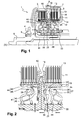
- This double wet clutch 1 comprises an axis of rotation X and two clutches 2 and 3 which succeed each other axially.
- the two clutches 2 and 3 are received in a common housing 4 mounted via a bearing 5 on an input hub 6 of the double clutch, this input hub 6 being rotated about the axis X by the crankshaft not shown of the vehicle.
- the input hub 6 is connected, via a link 8, to a flange 7 defining a driving member for the double clutch 1.
- the driving member 7 partially surrounds the first clutch 2.
- the latter comprises a first blade support input 10 carrying first input slats 11 and a first output slats support 12 carrying first output slats 13.
- the first clutch 2 further comprises a first pressure plate 14 passing through an opening 15 formed in the driving member 7, and a first reaction plate 16, the first inlet strips 11 being axially surrounded by the first pressure plate. 14 on the one hand, and by the first reaction plate 16 on the other hand, the latter respectively coming into contact with a first input end plate 11.
- the driving member 7 and the first input slat support 10 further comprise radial portions respectively designated 22 and 23 which are secured to the first reaction plate 16 via the same rivet 25.
- a radial passage is formed between the parts 22 and 23.
- the passage is formed here by reliefs 26 disjoint two by two and arranged on the radial portion 22.
- these reliefs 26 are bosses and the radial passage is formed by the vacuum between two bosses 26 consecutive angularly.
- This radial passage allows the oil present in a balancing chamber 29 delimited on one side by a first piston 30 and on the other side by a portion of the driving member 7 which then defines a first piston of equilibration 31, to gain the channel 24.
- the displacement of the first piston 30 makes it possible to modify the state of the first clutch 2, selectively creating a frictional contact between the first inlet slats 11 and the first outlet slats 13.
- Chamber 29 is supplied with liquid from a hollow hub 33, coaxial with a first outlet hub 34 and a second outlet hub 35, the latter being hollow and receiving internally the first outlet hub 34.
- the first output hub 34 is integral with the first output blade support 12 and thus defines a first driven member.
- the second clutch 3 has a structure close to that of the first clutch 2, differing essentially in that the channel 39 is formed between the axial portion 40 of an axial skirt 41 forming a second balancing piston, and the axial portion 42 the second input lamella support 44.
- the rivet 25 can make it possible to secure the following parts disposed axially in this order: the radial portion 46 of the axial skirt 41, the radial portion 48 of the second inlet lamella support 44, the second reaction plate 50, the first reaction plate 16, the radial portion 23 of the first inlet slat support 10 and the radial portion 22 of the driving member 7.
- the channel 24 of the first clutch 2 and the channel 39 of the second clutch 3 extend in the example described from an inlet 55 formed near the reaction plate 16 or 50 of this clutch 2 or 3.
- the first input slat support 10 has a plurality of passages 60 formed through the latter and allowing the liquid present in the channel 24 to come into contact with the slats of the first clutch 2.
- the first support 10 defines, as one moves around the X axis, a plurality of ribs 65 alternating with grooves 66 so as to form radial teeth.
- a passage 60 is formed in each rib 65.
- the passage 60 may not be arranged at the same axial height of a rib 65 to the adjacent rib 65, angularly speaking.
- the passage 60 can move axially from a first end-to-end slat towards the other, this same axial displacement of the passage starting again for the series of subsequent ribs.
- the second input lamellar support 44 may also have an alternation of ribs and grooves, radial passages, optionally axially offset from one rib to the other, being formed in these ribs.
- passages 60 or 67 may be arranged in said inlet lamellar support at different axial positions and at different angular positions, from a passage to the immediately following passage.
- the borrowing by the liquid flowing in the channel 24 of the first clutch 2 of the passages 60 is favored by the existence for this first clutch 2 of a plug 70 forming an end of the channel 24.
- the figure 4a represents the cap 70 isolated and the figure 4b represents the plug 70 in position on the first input lamella support 10.
- the plug 70 here has a substantially annular shape, being hollow and extending all around the axis X.
- the plug 70 is intended to be positioned substantially radially between the axial portions 20 and 21 of the driving member 7 and the first input slat support 10.
- the plug 70 has an axial dimension l1 smaller than that 12 of the axial portion 21 of the first input lamella support 10,11 being for example between 10% and 30%, especially equal to 15 or 20% of 12.
- the plug 70 is for example made of an elastically deformable material, for example example in an elastomer, the latter being in particular Viton R.
- the plug 70 is made of a plastic material, for example PA46-GF15 or PA66-GF30.
- the plug 70 has a portion 71 arranged axially at the passage 60 closest to the first pressure plate 14. This positioning of the plug 70 axially beyond the other passages 60 formed in the first input lamella holder 10 guarantees a free flow of liquid through them from the channel 24.
- This portion 71 of the cap 70 is here in contact via its radially inner edge 72 of the radially outer edge 73 of the axial portion 20 of the driving member 7. Via its edge radially outside 74, this portion 70 is spaced from the radially inner edge 75 of the first input slat support 10 at the passage 60, so that the flow of liquid through this passage 60 is allowed.
- the radially outer edge 74 of this portion 71 of the plug 70 defines an alternation of ribs 77 and grooves 78 around the perimeter of said plug.
- the ribs 77 formed in the plug 70 are here radially superimposed on the ribs 65 of the first input lamella support 10, and the grooves 78 formed in the plug 70 are radially superposed on the grooves 66 of the first lamella holder 10.
- a clearance can exist between the ribs 77 of the plug 70 and the ribs 65 of the first inlet slab support 10, so as to facilitate the introduction of the portion 71 of the plug into the channel 24 and the passage of the liquid in the passage 60.
- the plug 70 may comprise a portion 79 disposed axially beyond the passage 60, so as to prevent the liquid flowing in the channel 24 from flowing axially beyond this passage 60.
- this portion 79 is closer to the first pressure plate 14.
- the portion 79 comprises a radially outer edge 80 in contact with the radially inner edge 75 of the axial portion 21 of the first input slat support 10.
- This same portion 79 the plug 70 also has in the example considered a radially inner edge 82 at a distance from the radially outer edge 73 of the axial portion 20 of the drive member 7, so as to provide the latter with a clearance facilitating the mounting of the plug 70.
- the plug 70 may further comprise a portion 85 extending axially beyond the axial end 86 of the first inlet slab support 10, said portion 85 comprising an edge 87 in contact with said axial end 86 of the first input slat support 10.
- the portion 85 may extend radially beyond the axial portion 21 of the first input lamella support 10, coming for example radially at a portion of the first input lamellae 11.
- FIGS. 10a and 10b represent in part the first clutch 2 provided with the stopper 70 which has just been described, respectively in a plane intersecting a groove 66 of the first input lamella support 10 and in a plane intersecting a rib 65 of this first lamella support d entry 10.
- the oil gains from the hollow hub 33 the balancing chamber 29 delimited in part by the first piston 30 whose displacement makes it possible to modify the state of the first clutch 2.
- liquid then circulates between the radial portion 22 of the driving member 7 and the radial portion 23 of the first input lamella holder 10, then reaches the inlet 55 of the channel 24, then circulating axially between the parts 20 and 21 of the the driving member 7 and the first input lamella support 10.
- the liquid gains the space occupied by the first lamellae 11 and 13, through the successive unrepresented passages 60 that it encounters.
- This flow in the channel 24 is interrupted by the stopper 70 which thus forms an end of the channel 24.
- the plug 70 extends around the X axis, having an annular shape, as can be seen on the figure 11 .
- the stopper 70 is disposed exclusively axially beyond the passage 60 farthest from the first reaction plate 16, the stopper 70 then never being axially at the same level as this passage 60.
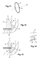
- the figure 12 is a sectional view at a groove 66 of the first input slat support 10 while the figure 13 is a sectional view at a rib 65 of this first input lamella support 10.
- the portion 91 of the plug 70 may extend discontinuously around the axis X. This portion 91 cooperates with grooves 65 formed in the first input lamella support 10 in order to angularly index the plug 70 relative to said first support 10 as well as to ensure a certain rigidity of the plug 70 in the event of compression.
- the portion 91 defines, for example, pins 92.
- the plug 70 may comprise an elastically deformable portion 94 adapted to be applied against a face of the first lamella end inlet 11 adapted to be pressed by the first pressure plate 14.
- This elastically deformable portion 94 ensures a seal between the first inlet slats 11 and the axial space disposed beyond said first end of the slat towards the outside of the first clutch 2.
- the stiffness of this elastically deformable portion 94 is advantageously less than that of a spring 97 interposed between two consecutive first inlet slats 11 and now the latter in a default position which is here a position in which the first clutch 2 is open.
- the figure 15 represents in full line the position of the elastically deformable portion 94 against the first end entry blade 11 when the first piston 30 is not activated to modify the state of the first clutch 2, and in dashed position of this portion 94 when the first piston 30 is activated.
- the elastically deformable portion 94 can be made in one piece with the rest of the plug 70.
- the figure 16 represents in a similar way to Figures 10a and 10b the circuit taken by the liquid from the hollow hub 33 until it comes into contact with the first lamellae 11 and 13, when the first clutch comprises a plug 70 according to the second example of implementation.
- the stopper 100 will now be described with reference to Figures 18 to 29 .
- the latter comprises a portion 101 disposed axially at the passage 67 farthest from the second reaction plate 50.
- Each zone of said portion 101 radially and axially facing a passage 67 is here arranged at a distance from the radially inner edge 103 of the axial portion 42 of the second inlet lamella support 44, so as to allow the circulation of the liquid present in the channel 39 through this passage 67.
- This portion of the plug 101 is in contact, via its radially inner edge 105, with the radially outer edge 106 of the axial portion 40 of the skirt 41.
- the shape of this portion 101 of the plug 100 makes it possible to guide the liquid towards the passages 67 formed through the second input slat support 44.
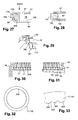
- the radially outer edge 108 of this portion 101 may define an alternation of ribs 110 and grooves 111 on the periphery of said plug 100. These ribs 110 and these grooves 111 are visible on the Figures 21 and 22 .
- these ribs 110 are radially superimposed on the ribs formed in the second inlet lamella support 44, and the grooves 111 formed in the cap are also radially superposed on the grooves of the second inlet lamella support 44.
- a clearance can exist between the ribs of the plug 100 and the ribs of the second inlet lamella support 44, so as to facilitate the introduction of said portion 101 of the plug 100 into the channel 39 and in order to promote the passage of oil through passage 67.
- the plug 100 comprises a portion 112 disposed axially beyond the passage 67, so as to prevent the liquid flowing in the channel 39 from flowing axially beyond this passage 67.
- This portion 112 may comprise at least one sealing lip 114 coming to bear against the radially inner edge 103 of the axial portion 42 of the second inlet lamella support 44.
- the sealing lip 114 is here deformable and it has a free end 115 received in a recess in the radially inner edge 103 of the second inlet slat support 44.
- the sealing lip 114 may deform all around the X axis.
- the sealing lip 114 can angularly define an alternation of ribs 120 and grooves 121. These ribs 120 and these grooves 121 are here respectively aligned axially with the ribs 110 and the grooves 111 defined by the portion 101 of the In the example under consideration, two substantially identical sealing lips are provided in the portion 112, these sealing lips 114 succeeding one another axially.
- the latter comprises a portion 125 disposed axially beyond the axial end 130 of the axial portion 42 of the second input lamella support 44.
- This portion 125 comprises in the example considered an edge 127 coming into contact with said axial end 130 of the axial portion 42 of the second input lamella support 44.
- This portion 125 may not protrude radially beyond the second input lamella support 44.
- this portion 125 may, in addition to extending axially beyond the axial end 130 of the axial portion 42 of the second inlet lamella support 44, also extend radially beyond this second support of This portion 125, which is then advantageously elastically deformable, can be applied against the outside face of the second end-entry blade 140 in contact with the second pressure plate.
- the stiffness of the elastically deformable portion 125 can be chosen to be smaller than the stiffness of the spring disposed between two second inlet blades 140 of the second clutch 3.
- the Figure 23a and 23b represent in part the second clutch 3 provided with the stopper 100 which has just been described, respectively in a plane intersecting a groove of the second input lamella support 44 and in a plane intersecting a rib of the second lamellae support input 44.
- the Figures 23a and 23b show, similarly to Figures 10a, 10b and 16 , the passage of the oil through the second clutch 3 from a hollow hub 133 secured to the second reaction plate 50 to the second inlet slats 140.
- the plug 100 is disposed axially beyond the passage 67 furthest from the second reaction plate 50, so as to prevent the liquid flowing in the channel 39 from flowing axially beyond this passage 67 .
- the plug 100 comprises in this example a portion 150 extending axially below the axial end 130 of the axial portion 42 of the second input lamella support 44. This portion extends here all around the X axis , as can be seen on the figure 24 . This portion 150 is visible on the Figures 25 and 26 which represent in section: the stopper 100, the axial portion 42 of the second input lamella support 44, and the axial portion 40 of the skirt 41 at a groove of the second input lamella support 44.
- This portion 150 is also visible on the Figures 27 and 28 which respectively represent in section and in plan view according to XVIII: the plug 100, the axial portion 42 of the second lamella support 44 and the axial portion 40 of the skirt 41 at a rib of the second support of inlet lamellae 44.
- this portion 150 has a radially inner edge 155 in contact with the radially inner edge 106 of the axial portion 40 of the skirt 41.
- This portion 150 further has a radially outer edge 157 substantially conical, so as to establish a linear contact with the radially inner edge 103 of the axial portion 42 of the second inlet lamella support 44.
- the plug 100 further comprises a portion 170 extending axially beyond the axial end 130 of the axial portion 42 of the second inlet slat support 44.
- this portion 170 extends discontinuously about the X axis, this portion 170 being formed for example by a plurality of separate arms.
- the portion 170 may extend axially beyond the axial end 180 of the axial portion 40 of the skirt 41.
- the portion 170 has, as can be seen in the Figures 27 and 29 a radial return 181 towards the X axis, this return 181 allowing attachment of the plug 100 on the skirt 41.
- the plug 100 can be made of elastomer, for example Viton R.
- the plug 100 can also be made of plastics material (s), for example PA46-GF15 or PA66-GF30.
- the figure 30 represents a part of a first clutch for double clutch, being for example the first clutch 2 described with reference to Figures 3 to 16
- the figure 31 represents a part of a second clutch for double clutch, being for example the double clutch 3 described with reference to Figures 17 to 29
- the figure 32 represents in isolation an input blade of one of the first and second clutch while the figure 33 represents a detail of the figure 32 .
- openings 200 are formed in each first intermediate inlet slat 11, ie other than a first end inlet slat, the latter end-slitting interacting with one of the first pressure plate 14 and of the first reaction plate 16. With these openings 200, liquid can move from a first end entry blade 11 to the other.
- Such passages are also formed in each first intermediate plate 140 of the second clutch.
- these openings are formed in the ribs 203 formed in the radially inner edge 205 of the intermediate inlet slats 11 or 140.
- the first end entry slats, as well as the second end entry slats, are devoid of such openings 200.
- the plug 70 for the first clutch 2 described with reference to Figures 3 to 16 may comprise one or more sealing lips similar to the sealing lips 114 described with reference to Figures 18 to 23 .
- the stopper 100 according to Figures 24 to 29 may also comprise one or more sealing lips similar to the sealing lips 114.
Landscapes
- Engineering & Computer Science (AREA)
- General Engineering & Computer Science (AREA)
- Mechanical Engineering (AREA)
- Hydraulic Clutches, Magnetic Clutches, Fluid Clutches, And Fluid Joints (AREA)
- Mechanical Operated Clutches (AREA)
Applications Claiming Priority (1)
| Application Number | Priority Date | Filing Date | Title |
|---|---|---|---|
| FR1458404A FR3025570B1 (fr) | 2014-09-08 | 2014-09-08 | Embrayage pour double embrayage humide |
Publications (3)
| Publication Number | Publication Date |
|---|---|
| EP2993371A2 true EP2993371A2 (de) | 2016-03-09 |
| EP2993371A3 EP2993371A3 (de) | 2016-10-19 |
| EP2993371B1 EP2993371B1 (de) | 2017-09-13 |
Family
ID=51987320
Family Applications (1)
| Application Number | Title | Priority Date | Filing Date |
|---|---|---|---|
| EP15180079.4A Not-in-force EP2993371B1 (de) | 2014-09-08 | 2015-08-06 | Kupplung für doppelnasskupplung |
Country Status (2)
| Country | Link |
|---|---|
| EP (1) | EP2993371B1 (de) |
| FR (1) | FR3025570B1 (de) |
Family Cites Families (4)
| Publication number | Priority date | Publication date | Assignee | Title |
|---|---|---|---|---|
| DE3725492A1 (de) * | 1987-07-31 | 1989-02-09 | Bayerische Motoren Werke Ag | Kraftrad mit einer mehrscheibenkupplung |
| DE10323515A1 (de) * | 2003-05-24 | 2004-12-23 | Dr.Ing.H.C. F. Porsche Ag | Kupplungsvorrichtung und Verfahren zum Betreiben einer Lamellenkupplung |
| JP4414996B2 (ja) * | 2006-11-21 | 2010-02-17 | 株式会社エクセディ | 複式クラッチ装置 |
| US20130153355A1 (en) * | 2011-12-16 | 2013-06-20 | Eaton Corporation | Hydraulic clutch assembly |
-
2014
- 2014-09-08 FR FR1458404A patent/FR3025570B1/fr not_active Expired - Fee Related
-
2015
- 2015-08-06 EP EP15180079.4A patent/EP2993371B1/de not_active Not-in-force
Non-Patent Citations (1)
| Title |
|---|
| None |
Also Published As
| Publication number | Publication date |
|---|---|
| EP2993371B1 (de) | 2017-09-13 |
| FR3025570A1 (fr) | 2016-03-11 |
| FR3025570B1 (fr) | 2018-02-23 |
| EP2993371A3 (de) | 2016-10-19 |
Similar Documents
| Publication | Publication Date | Title |
|---|---|---|
| EP2995832B1 (de) | Kupplung für doppelnasskupplung | |
| FR3063321B1 (fr) | Mecanisme d'embrayage humide dont la lubrification est amelioree | |
| FR2906329A1 (fr) | Structure de dispositif de transmission de couple de demarrage de moteur equipe d'un embrayage a galets | |
| EP0980482B1 (de) | Hydrodynamischer drehmomentwandler insbesondere für kraftfahrzeuge | |
| EP2993371B1 (de) | Kupplung für doppelnasskupplung | |
| EP3364063B1 (de) | Kompakter doppelkupplungsmechanismus, und übertragungssystem, das einen solchen doppelkupplungsmechanismus umfasst | |
| FR3062697A1 (fr) | Mecanisme a double embrayage demontable | |
| EP3239550B1 (de) | Anordnung für eine kupplungsvorrichtung, insbesondere für kraftfahrzeug | |
| FR3054868A1 (fr) | Mecanisme a double embrayage compact et systeme de transmission comprenant un tel mecanisme a double embrayage | |
| FR3067076A1 (fr) | Mecanisme d'embrayage comprenant deux ensembles separes par un dispositif de reglage d'une distance axiale | |
| WO2001036845A1 (fr) | Appareil d'accouplement hydrocinetique, notamment pour vehicule | |
| EP3635271A1 (de) | Kupplungsmechanismus mit zwei durch eine montagevorrichtung verbundenen anordnungen | |
| FR3066566A1 (fr) | Organes de transmission de force d'un mecanisme a double embrayages et mecanisme a double embrayages | |
| EP3411256B1 (de) | Verschlussvorrichtung für einen lufteinlass an der frontseite eines kraftfahrzeugs | |
| WO2018104139A1 (fr) | Dispositif d'amortissement de torsion | |
| FR3079573A1 (fr) | Porte-disques pour mecanisme d'embrayage de vehicule automobile et module d'embrayage comprenant un tel porte-disques | |
| EP3164620B1 (de) | Schwingungsdämpfer für fahrzeuggetriebesystem | |
| FR2928432A3 (fr) | Dispositif d'amortissement comportant des moyens de butee perfectionnee. | |
| FR2825770A1 (fr) | Appareil d'accouplement hydrocinetique, notamment pour vehicule automobile | |
| FR2749634A1 (fr) | Amortisseur de torsion pour embrayage de verrouillage, notamment de vehicule automobile | |
| FR3016669B1 (fr) | Embrayage a friction ainsi que procede servant a fabriquer un embrayage a friction | |
| WO1998053225A1 (fr) | Appareil d'accouplement hydrocinetique a piece d'entrainement de languettes, notamment pour vehicule automobile | |
| FR3060075A1 (fr) | Support pour lamelle d'embrayage humide et un embrayage humide comprenant de telles lamelles | |
| WO2018020156A1 (fr) | Dispositif de transmission de couple, notamment pour vehicule automobile | |
| EP3212951A1 (de) | Kupplungsscheibe für eine reibungskupplung |
Legal Events
| Date | Code | Title | Description |
|---|---|---|---|
| PUAI | Public reference made under article 153(3) epc to a published international application that has entered the european phase |
Free format text: ORIGINAL CODE: 0009012 |
|
| 17P | Request for examination filed |
Effective date: 20150806 |
|
| AK | Designated contracting states |
Kind code of ref document: A2 Designated state(s): AL AT BE BG CH CY CZ DE DK EE ES FI FR GB GR HR HU IE IS IT LI LT LU LV MC MK MT NL NO PL PT RO RS SE SI SK SM TR |
|
| AX | Request for extension of the european patent |
Extension state: BA ME |
|
| PUAL | Search report despatched |
Free format text: ORIGINAL CODE: 0009013 |
|
| AK | Designated contracting states |
Kind code of ref document: A3 Designated state(s): AL AT BE BG CH CY CZ DE DK EE ES FI FR GB GR HR HU IE IS IT LI LT LU LV MC MK MT NL NO PL PT RO RS SE SI SK SM TR |
|
| AX | Request for extension of the european patent |
Extension state: BA ME |
|
| RIC1 | Information provided on ipc code assigned before grant |
Ipc: F16D 21/06 20060101ALN20160915BHEP Ipc: F16D 25/12 20060101AFI20160915BHEP Ipc: F16D 25/0638 20060101ALI20160915BHEP |
|
| RIC1 | Information provided on ipc code assigned before grant |
Ipc: F16D 25/0638 20060101ALI20170220BHEP Ipc: F16D 21/06 20060101ALN20170220BHEP Ipc: F16D 25/12 20060101AFI20170220BHEP |
|
| GRAP | Despatch of communication of intention to grant a patent |
Free format text: ORIGINAL CODE: EPIDOSNIGR1 |
|
| INTG | Intention to grant announced |
Effective date: 20170403 |
|
| GRAS | Grant fee paid |
Free format text: ORIGINAL CODE: EPIDOSNIGR3 |
|
| GRAA | (expected) grant |
Free format text: ORIGINAL CODE: 0009210 |
|
| AK | Designated contracting states |
Kind code of ref document: B1 Designated state(s): AL AT BE BG CH CY CZ DE DK EE ES FI FR GB GR HR HU IE IS IT LI LT LU LV MC MK MT NL NO PL PT RO RS SE SI SK SM TR |
|
| REG | Reference to a national code |
Ref country code: GB Ref legal event code: FG4D Free format text: NOT ENGLISH |
|
| REG | Reference to a national code |
Ref country code: CH Ref legal event code: EP |
|
| REG | Reference to a national code |
Ref country code: IE Ref legal event code: FG4D Free format text: LANGUAGE OF EP DOCUMENT: FRENCH |
|
| REG | Reference to a national code |
Ref country code: AT Ref legal event code: REF Ref document number: 928463 Country of ref document: AT Kind code of ref document: T Effective date: 20171015 |
|
| REG | Reference to a national code |
Ref country code: DE Ref legal event code: R096 Ref document number: 602015004674 Country of ref document: DE |
|
| REG | Reference to a national code |
Ref country code: NL Ref legal event code: MP Effective date: 20170913 |
|
| REG | Reference to a national code |
Ref country code: LT Ref legal event code: MG4D |
|
| PG25 | Lapsed in a contracting state [announced via postgrant information from national office to epo] |
Ref country code: NO Free format text: LAPSE BECAUSE OF FAILURE TO SUBMIT A TRANSLATION OF THE DESCRIPTION OR TO PAY THE FEE WITHIN THE PRESCRIBED TIME-LIMIT Effective date: 20171213 Ref country code: FI Free format text: LAPSE BECAUSE OF FAILURE TO SUBMIT A TRANSLATION OF THE DESCRIPTION OR TO PAY THE FEE WITHIN THE PRESCRIBED TIME-LIMIT Effective date: 20170913 Ref country code: HR Free format text: LAPSE BECAUSE OF FAILURE TO SUBMIT A TRANSLATION OF THE DESCRIPTION OR TO PAY THE FEE WITHIN THE PRESCRIBED TIME-LIMIT Effective date: 20170913 Ref country code: SE Free format text: LAPSE BECAUSE OF FAILURE TO SUBMIT A TRANSLATION OF THE DESCRIPTION OR TO PAY THE FEE WITHIN THE PRESCRIBED TIME-LIMIT Effective date: 20170913 Ref country code: LT Free format text: LAPSE BECAUSE OF FAILURE TO SUBMIT A TRANSLATION OF THE DESCRIPTION OR TO PAY THE FEE WITHIN THE PRESCRIBED TIME-LIMIT Effective date: 20170913 |
|
| REG | Reference to a national code |
Ref country code: AT Ref legal event code: MK05 Ref document number: 928463 Country of ref document: AT Kind code of ref document: T Effective date: 20170913 |
|
| PG25 | Lapsed in a contracting state [announced via postgrant information from national office to epo] |
Ref country code: ES Free format text: LAPSE BECAUSE OF FAILURE TO SUBMIT A TRANSLATION OF THE DESCRIPTION OR TO PAY THE FEE WITHIN THE PRESCRIBED TIME-LIMIT Effective date: 20170913 Ref country code: GR Free format text: LAPSE BECAUSE OF FAILURE TO SUBMIT A TRANSLATION OF THE DESCRIPTION OR TO PAY THE FEE WITHIN THE PRESCRIBED TIME-LIMIT Effective date: 20171214 Ref country code: BG Free format text: LAPSE BECAUSE OF FAILURE TO SUBMIT A TRANSLATION OF THE DESCRIPTION OR TO PAY THE FEE WITHIN THE PRESCRIBED TIME-LIMIT Effective date: 20171213 Ref country code: RS Free format text: LAPSE BECAUSE OF FAILURE TO SUBMIT A TRANSLATION OF THE DESCRIPTION OR TO PAY THE FEE WITHIN THE PRESCRIBED TIME-LIMIT Effective date: 20170913 Ref country code: LV Free format text: LAPSE BECAUSE OF FAILURE TO SUBMIT A TRANSLATION OF THE DESCRIPTION OR TO PAY THE FEE WITHIN THE PRESCRIBED TIME-LIMIT Effective date: 20170913 |
|
| PG25 | Lapsed in a contracting state [announced via postgrant information from national office to epo] |
Ref country code: NL Free format text: LAPSE BECAUSE OF FAILURE TO SUBMIT A TRANSLATION OF THE DESCRIPTION OR TO PAY THE FEE WITHIN THE PRESCRIBED TIME-LIMIT Effective date: 20170913 |
|
| PG25 | Lapsed in a contracting state [announced via postgrant information from national office to epo] |
Ref country code: CZ Free format text: LAPSE BECAUSE OF FAILURE TO SUBMIT A TRANSLATION OF THE DESCRIPTION OR TO PAY THE FEE WITHIN THE PRESCRIBED TIME-LIMIT Effective date: 20170913 Ref country code: RO Free format text: LAPSE BECAUSE OF FAILURE TO SUBMIT A TRANSLATION OF THE DESCRIPTION OR TO PAY THE FEE WITHIN THE PRESCRIBED TIME-LIMIT Effective date: 20170913 Ref country code: PL Free format text: LAPSE BECAUSE OF FAILURE TO SUBMIT A TRANSLATION OF THE DESCRIPTION OR TO PAY THE FEE WITHIN THE PRESCRIBED TIME-LIMIT Effective date: 20170913 |
|
| PG25 | Lapsed in a contracting state [announced via postgrant information from national office to epo] |
Ref country code: IT Free format text: LAPSE BECAUSE OF FAILURE TO SUBMIT A TRANSLATION OF THE DESCRIPTION OR TO PAY THE FEE WITHIN THE PRESCRIBED TIME-LIMIT Effective date: 20170913 Ref country code: SK Free format text: LAPSE BECAUSE OF FAILURE TO SUBMIT A TRANSLATION OF THE DESCRIPTION OR TO PAY THE FEE WITHIN THE PRESCRIBED TIME-LIMIT Effective date: 20170913 Ref country code: EE Free format text: LAPSE BECAUSE OF FAILURE TO SUBMIT A TRANSLATION OF THE DESCRIPTION OR TO PAY THE FEE WITHIN THE PRESCRIBED TIME-LIMIT Effective date: 20170913 Ref country code: IS Free format text: LAPSE BECAUSE OF FAILURE TO SUBMIT A TRANSLATION OF THE DESCRIPTION OR TO PAY THE FEE WITHIN THE PRESCRIBED TIME-LIMIT Effective date: 20180113 Ref country code: AT Free format text: LAPSE BECAUSE OF FAILURE TO SUBMIT A TRANSLATION OF THE DESCRIPTION OR TO PAY THE FEE WITHIN THE PRESCRIBED TIME-LIMIT Effective date: 20170913 Ref country code: SM Free format text: LAPSE BECAUSE OF FAILURE TO SUBMIT A TRANSLATION OF THE DESCRIPTION OR TO PAY THE FEE WITHIN THE PRESCRIBED TIME-LIMIT Effective date: 20170913 |
|
| REG | Reference to a national code |
Ref country code: DE Ref legal event code: R097 Ref document number: 602015004674 Country of ref document: DE |
|
| PLBE | No opposition filed within time limit |
Free format text: ORIGINAL CODE: 0009261 |
|
| STAA | Information on the status of an ep patent application or granted ep patent |
Free format text: STATUS: NO OPPOSITION FILED WITHIN TIME LIMIT |
|
| PG25 | Lapsed in a contracting state [announced via postgrant information from national office to epo] |
Ref country code: DK Free format text: LAPSE BECAUSE OF FAILURE TO SUBMIT A TRANSLATION OF THE DESCRIPTION OR TO PAY THE FEE WITHIN THE PRESCRIBED TIME-LIMIT Effective date: 20170913 |
|
| 26N | No opposition filed |
Effective date: 20180614 |
|
| REG | Reference to a national code |
Ref country code: FR Ref legal event code: PLFP Year of fee payment: 4 |
|
| PG25 | Lapsed in a contracting state [announced via postgrant information from national office to epo] |
Ref country code: MT Free format text: LAPSE BECAUSE OF FAILURE TO SUBMIT A TRANSLATION OF THE DESCRIPTION OR TO PAY THE FEE WITHIN THE PRESCRIBED TIME-LIMIT Effective date: 20170913 |
|
| PG25 | Lapsed in a contracting state [announced via postgrant information from national office to epo] |
Ref country code: SI Free format text: LAPSE BECAUSE OF FAILURE TO SUBMIT A TRANSLATION OF THE DESCRIPTION OR TO PAY THE FEE WITHIN THE PRESCRIBED TIME-LIMIT Effective date: 20170913 |
|
| PG25 | Lapsed in a contracting state [announced via postgrant information from national office to epo] |
Ref country code: MC Free format text: LAPSE BECAUSE OF FAILURE TO SUBMIT A TRANSLATION OF THE DESCRIPTION OR TO PAY THE FEE WITHIN THE PRESCRIBED TIME-LIMIT Effective date: 20170913 |
|
| REG | Reference to a national code |
Ref country code: CH Ref legal event code: PL |
|
| PG25 | Lapsed in a contracting state [announced via postgrant information from national office to epo] |
Ref country code: CH Free format text: LAPSE BECAUSE OF NON-PAYMENT OF DUE FEES Effective date: 20180831 Ref country code: LI Free format text: LAPSE BECAUSE OF NON-PAYMENT OF DUE FEES Effective date: 20180831 Ref country code: LU Free format text: LAPSE BECAUSE OF NON-PAYMENT OF DUE FEES Effective date: 20180806 |
|
| REG | Reference to a national code |
Ref country code: BE Ref legal event code: MM Effective date: 20180831 |
|
| REG | Reference to a national code |
Ref country code: IE Ref legal event code: MM4A |
|
| PG25 | Lapsed in a contracting state [announced via postgrant information from national office to epo] |
Ref country code: IE Free format text: LAPSE BECAUSE OF NON-PAYMENT OF DUE FEES Effective date: 20180806 |
|
| PG25 | Lapsed in a contracting state [announced via postgrant information from national office to epo] |
Ref country code: BE Free format text: LAPSE BECAUSE OF NON-PAYMENT OF DUE FEES Effective date: 20180831 |
|
| PG25 | Lapsed in a contracting state [announced via postgrant information from national office to epo] |
Ref country code: TR Free format text: LAPSE BECAUSE OF FAILURE TO SUBMIT A TRANSLATION OF THE DESCRIPTION OR TO PAY THE FEE WITHIN THE PRESCRIBED TIME-LIMIT Effective date: 20170913 |
|
| GBPC | Gb: european patent ceased through non-payment of renewal fee |
Effective date: 20190806 |
|
| PG25 | Lapsed in a contracting state [announced via postgrant information from national office to epo] |
Ref country code: PT Free format text: LAPSE BECAUSE OF FAILURE TO SUBMIT A TRANSLATION OF THE DESCRIPTION OR TO PAY THE FEE WITHIN THE PRESCRIBED TIME-LIMIT Effective date: 20170913 |
|
| PG25 | Lapsed in a contracting state [announced via postgrant information from national office to epo] |
Ref country code: CY Free format text: LAPSE BECAUSE OF FAILURE TO SUBMIT A TRANSLATION OF THE DESCRIPTION OR TO PAY THE FEE WITHIN THE PRESCRIBED TIME-LIMIT Effective date: 20170913 Ref country code: HU Free format text: LAPSE BECAUSE OF FAILURE TO SUBMIT A TRANSLATION OF THE DESCRIPTION OR TO PAY THE FEE WITHIN THE PRESCRIBED TIME-LIMIT; INVALID AB INITIO Effective date: 20150806 Ref country code: MK Free format text: LAPSE BECAUSE OF NON-PAYMENT OF DUE FEES Effective date: 20170913 |
|
| PG25 | Lapsed in a contracting state [announced via postgrant information from national office to epo] |
Ref country code: AL Free format text: LAPSE BECAUSE OF FAILURE TO SUBMIT A TRANSLATION OF THE DESCRIPTION OR TO PAY THE FEE WITHIN THE PRESCRIBED TIME-LIMIT Effective date: 20170913 |
|
| PG25 | Lapsed in a contracting state [announced via postgrant information from national office to epo] |
Ref country code: GB Free format text: LAPSE BECAUSE OF NON-PAYMENT OF DUE FEES Effective date: 20190806 |
|
| P01 | Opt-out of the competence of the unified patent court (upc) registered |
Effective date: 20230528 |
|
| PGFP | Annual fee paid to national office [announced via postgrant information from national office to epo] |
Ref country code: FR Payment date: 20230828 Year of fee payment: 9 Ref country code: DE Payment date: 20230808 Year of fee payment: 9 |
|
| REG | Reference to a national code |
Ref country code: DE Ref legal event code: R119 Ref document number: 602015004674 Country of ref document: DE |
|
| PG25 | Lapsed in a contracting state [announced via postgrant information from national office to epo] |
Ref country code: DE Free format text: LAPSE BECAUSE OF NON-PAYMENT OF DUE FEES Effective date: 20250301 |
|
| PG25 | Lapsed in a contracting state [announced via postgrant information from national office to epo] |
Ref country code: FR Free format text: LAPSE BECAUSE OF NON-PAYMENT OF DUE FEES Effective date: 20240831 |