EP2990918A2 - Kontaktloses steuerungsverfahren unter verwendung eines polarisierenden stiftes und system zur implementierung davon - Google Patents
Kontaktloses steuerungsverfahren unter verwendung eines polarisierenden stiftes und system zur implementierung davon Download PDFInfo
- Publication number
- EP2990918A2 EP2990918A2 EP14788140.3A EP14788140A EP2990918A2 EP 2990918 A2 EP2990918 A2 EP 2990918A2 EP 14788140 A EP14788140 A EP 14788140A EP 2990918 A2 EP2990918 A2 EP 2990918A2
- Authority
- EP
- European Patent Office
- Prior art keywords
- polarization
- marker
- receiver
- polarizer
- polarization marker
- Prior art date
- Legal status (The legal status is an assumption and is not a legal conclusion. Google has not performed a legal analysis and makes no representation as to the accuracy of the status listed.)
- Withdrawn
Links
Images


Classifications
-
- G—PHYSICS
- G01—MEASURING; TESTING
- G01J—MEASUREMENT OF INTENSITY, VELOCITY, SPECTRAL CONTENT, POLARISATION, PHASE OR PULSE CHARACTERISTICS OF INFRARED, VISIBLE OR ULTRAVIOLET LIGHT; COLORIMETRY; RADIATION PYROMETRY
- G01J4/00—Measuring polarisation of light
- G01J4/04—Polarimeters using electric detection means
-
- G—PHYSICS
- G06—COMPUTING OR CALCULATING; COUNTING
- G06F—ELECTRIC DIGITAL DATA PROCESSING
- G06F3/00—Input arrangements for transferring data to be processed into a form capable of being handled by the computer; Output arrangements for transferring data from processing unit to output unit, e.g. interface arrangements
- G06F3/01—Input arrangements or combined input and output arrangements for interaction between user and computer
- G06F3/03—Arrangements for converting the position or the displacement of a member into a coded form
- G06F3/041—Digitisers, e.g. for touch screens or touch pads, characterised by the transducing means
- G06F3/042—Digitisers, e.g. for touch screens or touch pads, characterised by the transducing means by opto-electronic means
-
- G—PHYSICS
- G06—COMPUTING OR CALCULATING; COUNTING
- G06F—ELECTRIC DIGITAL DATA PROCESSING
- G06F3/00—Input arrangements for transferring data to be processed into a form capable of being handled by the computer; Output arrangements for transferring data from processing unit to output unit, e.g. interface arrangements
- G06F3/01—Input arrangements or combined input and output arrangements for interaction between user and computer
- G06F3/03—Arrangements for converting the position or the displacement of a member into a coded form
- G06F3/0304—Detection arrangements using opto-electronic means
- G06F3/0325—Detection arrangements using opto-electronic means using a plurality of light emitters or reflectors or a plurality of detectors forming a reference frame from which to derive the orientation of the object, e.g. by triangulation or on the basis of reference deformation in the picked up image
-
- G—PHYSICS
- G06—COMPUTING OR CALCULATING; COUNTING
- G06F—ELECTRIC DIGITAL DATA PROCESSING
- G06F3/00—Input arrangements for transferring data to be processed into a form capable of being handled by the computer; Output arrangements for transferring data from processing unit to output unit, e.g. interface arrangements
- G06F3/01—Input arrangements or combined input and output arrangements for interaction between user and computer
- G06F3/03—Arrangements for converting the position or the displacement of a member into a coded form
- G06F3/033—Pointing devices displaced or positioned by the user, e.g. mice, trackballs, pens or joysticks; Accessories therefor
- G06F3/0354—Pointing devices displaced or positioned by the user, e.g. mice, trackballs, pens or joysticks; Accessories therefor with detection of 2D relative movements between the device, or an operating part thereof, and a plane or surface, e.g. 2D mice, trackballs, pens or pucks
- G06F3/03545—Pens or stylus
-
- H—ELECTRICITY
- H04—ELECTRIC COMMUNICATION TECHNIQUE
- H04N—PICTORIAL COMMUNICATION, e.g. TELEVISION
- H04N23/00—Cameras or camera modules comprising electronic image sensors; Control thereof
- H04N23/20—Cameras or camera modules comprising electronic image sensors; Control thereof for generating image signals from infrared radiation only
-
- H—ELECTRICITY
- H04—ELECTRIC COMMUNICATION TECHNIQUE
- H04N—PICTORIAL COMMUNICATION, e.g. TELEVISION
- H04N23/00—Cameras or camera modules comprising electronic image sensors; Control thereof
- H04N23/50—Constructional details
- H04N23/55—Optical parts specially adapted for electronic image sensors; Mounting thereof
-
- H—ELECTRICITY
- H04—ELECTRIC COMMUNICATION TECHNIQUE
- H04N—PICTORIAL COMMUNICATION, e.g. TELEVISION
- H04N23/00—Cameras or camera modules comprising electronic image sensors; Control thereof
- H04N23/90—Arrangement of cameras or camera modules, e.g. multiple cameras in TV studios or sports stadiums
-
- G—PHYSICS
- G02—OPTICS
- G02B—OPTICAL ELEMENTS, SYSTEMS OR APPARATUS
- G02B3/00—Simple or compound lenses
- G02B3/02—Simple or compound lenses with non-spherical faces
-
- G—PHYSICS
- G02—OPTICS
- G02B—OPTICAL ELEMENTS, SYSTEMS OR APPARATUS
- G02B5/00—Optical elements other than lenses
- G02B5/08—Mirrors
- G02B5/10—Mirrors with curved faces
-
- G—PHYSICS
- G02—OPTICS
- G02B—OPTICAL ELEMENTS, SYSTEMS OR APPARATUS
- G02B5/00—Optical elements other than lenses
- G02B5/30—Polarising elements
- G02B5/3025—Polarisers, i.e. arrangements capable of producing a definite output polarisation state from an unpolarised input state
Definitions
- the invention relates to the electro-optical industry, more specifically to the method and device for non-contact data control and input.
- the downside of those presenters and markers for non-contact data control and input is their low positioning accuracy and large size of the devices themselves.
- the downsides of the technology of video-based gesture recognition are a low positioning accuracy and a low response rate due to complexity of video data processing.
- the invention called "Method of non-contact control using a laser marker and a laser marker system for its implementation" ( Russian application number 2012102208 ) serves as a prototype.
- This prototype for non-contact data control and input consists of a laser marker and a receiver by which it is possible to identify the spatial position of the laser marker relative to the receiver; then this position gets interpreted into control commands, in particular in order to control the cursor on the monitor screen on which the receiver connected to the PC is installed. It is also possible to perform 3D positioning based on detection of the laser marker's spatial position relative to the receiver for the purpose of its use in computer games, simulators, graphic application, remote control of manipulators and devices, etc.
- the object of the invention is creation of a fundamentally new device consisting of a polarization marker and a receiver that is based on other optical processes, which allows making the device cheaper and more reliable due to elimination of mechanical components.
- polarimeters 3 connected to microprocessor 4 that processes signals coming from polarimeters, are installed on receiver 1 (see Fig. 1 ) located in working plane 2 of a computer monitor or a TV-set, or a projection screen, or any other device.
- the signals are formed by light pulses coming from polarization marker 5.
- the polarization marker itself consists of hollow cylinder polarizer 6 ( Fig. 2 ), light source 7 emitting in the infrared spectrum, reflector 8, lenses 9 and 10, and transparent casing 11.
- Hollow cylinder polarizer 6 is made of a polymer polarizing film. Such a film can be fabricated by applying a grating, which is a variation of diffraction grating, on it.
- this grating is a series of triangular rulings.
- Aluminum coating is deposited by spraying on one edge of each ruling.
- Such grating on a polymer film with hundreds or thousands of rulings per millimeter has a polarizing effect on the infrared spectrum.
- this film can be bent while still maintaining its polarizing properties.
- the film is rolled as a cylinder into hollow tubular polarizer 6.
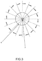
- part of the beams passes through the walls of cylindrical hollow polarizer 6 and such beams become polarized, wherein the direction of polarization vectors of radially emitted beams is axially symmetrical about the virtual axis of polarization marker 5.
- the grating rulings can be arranged along the cylinder axis or across it, around the cylinder. Depending on the direction of rulings on the cylinder, direction of the polarization vectors is axially symmetrical in a circle about the virtual axis of the polarization marker ( Fig. 3 ) or polarization vectors lie in the planes intersecting along this axis.
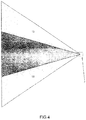
- the invention uses an array of lenses and reflectors. To that end, beams emitted by light source 7 ( Fig.
- central segment 12 located along the virtual axis of the cylinder polarizer under the aperture slope of about 30 degrees
- side segment 13 Light source 7 ( Fig. 5 ) is located at the rear of hollow cylinder polarizer 6. The light emitted by source 7 is directed on conical concave lens 9. The beam bundle of the central segment is converted into a Bessel bundle, and the aperture slope for both segments is increased. Refracted beams are directed on the walls of polarizer 6 on which cylindrical reflector 8 with a mirror-like inner surface is put. Consequently, beams passing through the polarizer fall on reflector 8 and are reflected in the direction of the front end of the polarization marker with negative lens 10 installed on it. The beams of the central segment fall on lens 10.
- This lens 10 is made in a form of a conical convex lens. It refracts beams in such a way so that the extreme beams intersect the virtual axis of cylinder polarizer 6, whereas the beams of the side segment are passed outside through transparent casing 11.
- transparent casing 11 ( Fig. 6 ) is made cross-flexed and lens 10 is made in a form of a flat-convex lens with a concave conical face (option A).
- the opposite face of lens 10 can also be made concave, wherein negative lens 10 is made in a form of a conical concave-convex lens (option B).
- beams that passed through cylinder polarizer 6 are then refracted by elongated negative conical torpedo-like lens 14 ( Fig. 7 ), installed above cylinder polarizer 6.
- elongated negative conical torpedo-like lens 14 Fig. 7
- a cylindrical reflector is not used.
- the flat face of the lens can be made convex.
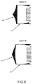
- the polarization marker is intended for use as a handling device operated by a user. However, to interpret the motion of the polarization marker into control commands, the direction and position of the polarization marker have to be identified. This task is fulfilled by receiver 1 and microprocessor 4 connected to it. Receiver 1 consists of several polarimeters 3 placed in working plane 2 and spaced at a predetermined distance. If a monitor is used as the working plane, it is practical to place polarimeters around the perimeter of the monitor. The minimum number of polarimeters in the receiver is two. Non-cooled bolometers 15 ( Fig. 8 ) consisting of two, three or four crossed gratings may be used as polarimeters.
- each bolometer consists of several parallel metal wires with a diameter of several microns.
- the wire can be made of nickel or platinum.
- the emitted light heats up the wires thus changing its electrical resistance.
- the direction of an electric vector of a linearly polarized incident wave in relation to the direction of the bolometer wire affects the change in its electrical resistance. Therefore, by measuring the relevant changes in the electrical resistance in all gratings, one can calculate the polarization direction of incident light. The more gratings in the polarimeter, the higher the measuring accuracy.
- Each bolometer grating is connected to a fast high-sensitivity analog to digital converter, which in its turn is connected to microprocessor 4.
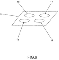
- Another type of polarimeters can be made by using a group of linearly polarized analyzers.
- Each of the said analyzers is a dichroic linear polarizer.
- the analyzers are placed adjacent to each other, in one plane, with direction of linear polarization of each analyzer turned in relation to others, e.g. azimuth of the first analyzer 16 ( Fig. 9 ) is 0 degrees, azimuth of second analyzer 17 is 45 degrees, azimuth of third analyzer 18 is 90 degrees, and azimuth of fourth analyzer 19 is 135 degrees.
- a photodetector is placed under each analyzer. Each photodetector is connected to a fast high-sensitivity analog to digital converter that is connected to microprocessor 4.
- light filters can be installed above the polarimeters for transmission of a narrow spectrum of light emitted by light source 7.
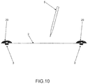
- the polarimeters can receive the light from the polarization marker when it is located near the working plane, meniscus 'fish-eye' lenses 20 are installed above polarimeters 3 ( Fig. 10 ) in particular with a viewing angle of no less than 180 degrees. If polarimeter 3 consists of a set of analyzers, it is more practical to install meniscus lens 20 above each analyzer to eliminate any distortion caused by focusing or spot displacement.
- At least two high-speed digital cameras spaced at a certain distance and connected to the microprocessor, can be installed in the receiver.
- Meniscus 'fish-eye' lenses are also installed above the digital cameras. Apart from meniscus lenses, additional lenses can be used for focusing the light.
- a non-contact control method using polarization marker 5 is implemented in the following way.
- Source of light 7 is switched on inside polarization marker 5 and starts emitting light pulses with a predetermined frequency.
- Infrared light emitted by light source 7 passes through the walls of a hollow cylinder polarizer and a system of lenses, and reflectors in polarization marker 5 as described above, and the exiting beams are linearly polarized.
- the directions of the polarization vectors of the beams radially exiting the polarization marker are axially symmetrical about the virtual axis of polarization marker 5.
- the beams from light source 7 are passed through hollow cylinder polarizer 6 with part of beams being refracted by negative lens 10.
- Polarization marker 5 In space in front of working plane 2 on which receiver 1 is fixed. There are at least two polarimeters 3 spaced and fixed on sides of receiver 1. Light from polarization marker 5 falls on polarimeters 3. Polarimeters 3 use a known method of differential measurement of the linear polarization. Polarimeters 3 are placed in such a way so that they allow determining the polarization direction along working plane 2. Signals from the polarimeters are sent to the analog to digital converter and then are sent to microprocessor 4 where final processing is performed. Light filters that pass a narrow spectrum of light emitted by light source 7 and the frequency modulation of received signals by the known pulse frequency of light source 7 are used in order to filter out any noise or interference.
- Polarimeters 3 are used to locate the direction of polarization vectors in working plane 2 and then using microprocessor 4 and the required software, virtual lines are drawn along the direction of vectors; their intersection is used to identify the intersection points of virtual lines in working plane 2 that shows the direction of polarization marker 5. Then, the resulting information is interpreted by microprocessor 4 into control commands.
- each digital camera 21 can be positioned under bolometer 15 and common meniscus lens 20.
- a polarization marker can be made by using an infrared semiconductor light diode, the hollow polarization cylinder can be made using a fluoroplastic substrate onto which rulings of the required pattern are applied by a photolithography method.
- known materials for the infrared optics are used, e.g. zinc selenide, etc.
- Optronics of the receiver is made on the basis of either semiconductor photodiodes and CCD matrices or using non-cooled grating bolometers, the grating of which can be made of micron-scale nickel wire.
- a microprocessor and an analog to digital converter are made of existing hardware components that can be connected to a PC, for example, via USB.
- the polarization marker can be powered by standard batteries or rechargeable batteries.
Landscapes
- Engineering & Computer Science (AREA)
- Theoretical Computer Science (AREA)
- General Engineering & Computer Science (AREA)
- Physics & Mathematics (AREA)
- General Physics & Mathematics (AREA)
- Human Computer Interaction (AREA)
- Signal Processing (AREA)
- Multimedia (AREA)
- Spectroscopy & Molecular Physics (AREA)
- Length Measuring Devices By Optical Means (AREA)
- Polarising Elements (AREA)
- Optics & Photonics (AREA)
- Position Input By Displaying (AREA)
Applications Claiming Priority (2)
| Application Number | Priority Date | Filing Date | Title |
|---|---|---|---|
| RU2013119124/08A RU2573245C2 (ru) | 2013-04-24 | 2013-04-24 | Способ бесконтактного управления с помощью поляризационного маркера и комплекс его реализующий |
| PCT/RU2014/000270 WO2014175779A2 (ru) | 2013-04-24 | 2014-04-14 | Способ бесконтактного управления с помощью поляризационного маркера и комплекс его реализующий |
Publications (2)
| Publication Number | Publication Date |
|---|---|
| EP2990918A2 true EP2990918A2 (de) | 2016-03-02 |
| EP2990918A4 EP2990918A4 (de) | 2017-01-11 |
Family
ID=51792474
Family Applications (1)
| Application Number | Title | Priority Date | Filing Date |
|---|---|---|---|
| EP14788140.3A Withdrawn EP2990918A4 (de) | 2013-04-24 | 2014-04-14 | Kontaktloses steuerungsverfahren unter verwendung eines polarisierenden stiftes und system zur implementierung davon |
Country Status (9)
| Country | Link |
|---|---|
| US (1) | US20160041036A1 (de) |
| EP (1) | EP2990918A4 (de) |
| JP (1) | JP6323731B2 (de) |
| KR (1) | KR101832044B1 (de) |
| CN (1) | CN105144055A (de) |
| BR (1) | BR112015027105A2 (de) |
| CA (1) | CA2910282A1 (de) |
| RU (1) | RU2573245C2 (de) |
| WO (1) | WO2014175779A2 (de) |
Families Citing this family (2)
| Publication number | Priority date | Publication date | Assignee | Title |
|---|---|---|---|---|
| CN104635960B (zh) * | 2015-02-27 | 2017-10-13 | 深圳市掌网科技股份有限公司 | 一种可定位的红外书画笔及其定位方法 |
| TWI614657B (zh) * | 2016-12-16 | 2018-02-11 | 奇象光學有限公司 | 光學膜片以及使用者輸入系統 |
Family Cites Families (25)
| Publication number | Priority date | Publication date | Assignee | Title |
|---|---|---|---|---|
| JPS60119155U (ja) * | 1984-01-20 | 1985-08-12 | 旭光学工業株式会社 | 光学式リモ−トコントロ−ラの受信装置 |
| DE3751226T2 (de) * | 1986-11-27 | 1995-12-07 | Fenner David Fenton | Fernsteuerungssysteme. |
| JP3134322B2 (ja) * | 1991-03-05 | 2001-02-13 | ソニー株式会社 | 遠隔制御装置及び遠隔制御方法 |
| US5926168A (en) * | 1994-09-30 | 1999-07-20 | Fan; Nong-Qiang | Remote pointers for interactive televisions |
| JP3841132B2 (ja) * | 1998-06-01 | 2006-11-01 | 株式会社ソニー・コンピュータエンタテインメント | 入力位置検出装置及びエンタテインメントシステム |
| JP2000347806A (ja) * | 1999-06-03 | 2000-12-15 | Canon Inc | 座標入力ペン |
| JP3684094B2 (ja) * | 1999-01-19 | 2005-08-17 | ペンタックス株式会社 | 走査光学系 |
| JP2002032188A (ja) | 2000-07-19 | 2002-01-31 | Newcom:Kk | 光方式座標入力装置 |
| US20030222849A1 (en) * | 2002-05-31 | 2003-12-04 | Starkweather Gary K. | Laser-based user input device for electronic projection displays |
| US9229540B2 (en) * | 2004-01-30 | 2016-01-05 | Electronic Scripting Products, Inc. | Deriving input from six degrees of freedom interfaces |
| EP1721201A1 (de) * | 2004-02-18 | 2006-11-15 | Corning Incorporated | Katadioptrisches abbildungssystem zur abbildung mit hoher numerischer apertur mit tief-ultraviolett-licht |
| CN1645040A (zh) * | 2005-01-20 | 2005-07-27 | 上海交通大学 | 微位移的平面光波导测量装置 |
| FR2883417B1 (fr) * | 2005-03-16 | 2007-05-11 | Ulis Soc Par Actions Simplifie | Detecteur bolometrique, dispositif de detection infrarouge mettant en oeuvre un tel detecteur et procede de fabrication de ce detecteur |
| JP2006260487A (ja) * | 2005-03-18 | 2006-09-28 | Fuji Xerox Co Ltd | ポインタシステム |
| WO2007141826A1 (ja) * | 2006-05-26 | 2007-12-13 | Nalux Co., Ltd. | 赤外光源 |
| US8291346B2 (en) | 2006-11-07 | 2012-10-16 | Apple Inc. | 3D remote control system employing absolute and relative position detection |
| US8272749B2 (en) * | 2007-04-25 | 2012-09-25 | Thomson Licensing | High resolution segmented 3D projection system |
| JP4435867B2 (ja) * | 2008-06-02 | 2010-03-24 | パナソニック株式会社 | 法線情報を生成する画像処理装置、方法、コンピュータプログラム、および、視点変換画像生成装置 |
| KR101589163B1 (ko) * | 2008-12-11 | 2016-01-28 | 삼성전자주식회사 | 단말기의 입력 방법 및 시스템 |
| US9244525B2 (en) * | 2009-02-19 | 2016-01-26 | Disney Enterprises, Inc. | System and method for providing user interaction with projected three-dimensional environments |
| JP5541653B2 (ja) * | 2009-04-23 | 2014-07-09 | キヤノン株式会社 | 撮像装置及びその制御方法 |
| WO2012064520A1 (en) * | 2010-11-12 | 2012-05-18 | 3M Innovative Properties Company | Interactive polarization-preserving projection display |
| GB201022138D0 (en) * | 2010-12-31 | 2011-02-02 | Barco Nv | Display device and means to measure and isolate the ambient light |
| US8670021B2 (en) * | 2011-07-19 | 2014-03-11 | Apstec Systems Ltd | Method for stand off inspection of target in monitored space |
| RU2012102208A (ru) | 2012-01-23 | 2013-07-27 | Дмитрий Александрович Гертнер | Способ бесконтактного управления с помощью лазерного маркера и комплекс лазерный маркер, его реализующий |
-
2013
- 2013-04-24 RU RU2013119124/08A patent/RU2573245C2/ru not_active IP Right Cessation
-
2014
- 2014-04-14 EP EP14788140.3A patent/EP2990918A4/de not_active Withdrawn
- 2014-04-14 CA CA2910282A patent/CA2910282A1/en not_active Abandoned
- 2014-04-14 KR KR1020157033481A patent/KR101832044B1/ko not_active Expired - Fee Related
- 2014-04-14 WO PCT/RU2014/000270 patent/WO2014175779A2/ru not_active Ceased
- 2014-04-14 JP JP2016510646A patent/JP6323731B2/ja active Active
- 2014-04-14 CN CN201480023756.6A patent/CN105144055A/zh active Pending
- 2014-04-14 BR BR112015027105A patent/BR112015027105A2/pt not_active IP Right Cessation
-
2015
- 2015-10-23 US US14/921,262 patent/US20160041036A1/en not_active Abandoned
Also Published As
| Publication number | Publication date |
|---|---|
| BR112015027105A2 (pt) | 2018-07-24 |
| CA2910282A1 (en) | 2014-10-30 |
| RU2573245C2 (ru) | 2016-01-20 |
| KR101832044B1 (ko) | 2018-02-23 |
| KR20160006184A (ko) | 2016-01-18 |
| WO2014175779A3 (ru) | 2015-04-09 |
| WO2014175779A2 (ru) | 2014-10-30 |
| JP6323731B2 (ja) | 2018-05-16 |
| RU2013119124A (ru) | 2014-10-27 |
| CN105144055A (zh) | 2015-12-09 |
| US20160041036A1 (en) | 2016-02-11 |
| JP2016529571A (ja) | 2016-09-23 |
| EP2990918A4 (de) | 2017-01-11 |
Similar Documents
| Publication | Publication Date | Title |
|---|---|---|
| US8730167B2 (en) | Pointing device with optical positioning on low-diffusive surfaces | |
| CN109196378B (zh) | 用于遥感接收器的光学系统 | |
| JPH08506193A (ja) | ペンの視覚的検出のための拡散支援による位置標定用装置および方法 | |
| US12078546B2 (en) | Sequential beam splitting in a radiation sensing apparatus | |
| US10281551B2 (en) | Compound eye laser tracking device | |
| US20180038730A1 (en) | Optical detector and system therefor | |
| EP2990918A2 (de) | Kontaktloses steuerungsverfahren unter verwendung eines polarisierenden stiftes und system zur implementierung davon | |
| US11422264B2 (en) | Optical remote sensing | |
| US20190154885A1 (en) | Panoramic imaging system | |
| JP4114637B2 (ja) | 位置計測システム | |
| US20230421268A1 (en) | Receiver, receiving device, communication device, and communication system | |
| JP7284979B2 (ja) | 位置決めシステムおよび関連方法 | |
| US10070080B2 (en) | Multi-directional, multi-spectral star tracker with a common aperture and common camera | |
| RU2277250C2 (ru) | Пассивное несканирующее телевизионное устройство для определения азимута и (или) координат объекта | |
| RU2008101723A (ru) | Способ ввода с помощью дистанционного указателя, комплекс дистанционный указатель его реализующий и способ идентификации с их помощью | |
| WO2013112073A1 (ru) | Способ и комплекс для управления с помощью лазерного маркера | |
| US9599697B2 (en) | Non-contact fiber optic localization and tracking system | |
| CN203661233U (zh) | 遥控器和显示屏 | |
| KR100763941B1 (ko) | 전방향 스테레오 영상 장치 | |
| RU2556282C1 (ru) | Способ определения пространственной ориентации объекта с помощью оптико-электронной системы и уголкового отражателя | |
| RU2634372C1 (ru) | Устройство для контроля углового положения дифракционных порядков дифракционных элементов (варианты) | |
| Ieng | Designing non constant resolution vision sensors via photosites rearrangement | |
| CN104482857A (zh) | 三维psd位置传感器 |
Legal Events
| Date | Code | Title | Description |
|---|---|---|---|
| PUAI | Public reference made under article 153(3) epc to a published international application that has entered the european phase |
Free format text: ORIGINAL CODE: 0009012 |
|
| 17P | Request for examination filed |
Effective date: 20151120 |
|
| AK | Designated contracting states |
Kind code of ref document: A2 Designated state(s): AL AT BE BG CH CY CZ DE DK EE ES FI FR GB GR HR HU IE IS IT LI LT LU LV MC MK MT NL NO PL PT RO RS SE SI SK SM TR |
|
| AX | Request for extension of the european patent |
Extension state: BA ME |
|
| DAX | Request for extension of the european patent (deleted) | ||
| A4 | Supplementary search report drawn up and despatched |
Effective date: 20161213 |
|
| RIC1 | Information provided on ipc code assigned before grant |
Ipc: G06F 3/0354 20130101ALI20161207BHEP Ipc: G02B 27/28 20060101ALI20161207BHEP Ipc: G06F 3/042 20060101AFI20161207BHEP Ipc: G08C 23/04 20060101ALI20161207BHEP |
|
| STAA | Information on the status of an ep patent application or granted ep patent |
Free format text: STATUS: THE APPLICATION IS DEEMED TO BE WITHDRAWN |
|
| 18D | Application deemed to be withdrawn |
Effective date: 20191101 |